Article

Influence of Different Binders and Severe Environmental Conditions on the Tribological and Electrochemical Behaviour of WC-Based Composites

1
INEGI—Institute of Science and Innovation in Mechanical and Industrial Engineering, Department of Metallurgical and Materials Engineering, University of Porto, Rua Dr. Roberto Frias, 4200-465 Porto, Portugal
2
DURIT—Metalurgia Portuguesa do Tungsténio Lda, 3854-909 Albergaria-a-Velha, Portugal
3
CEMMPRE—Centre for Mechanical Engineering, Materials and Processes, University of Coimbra, Rua Luís Reis Santos, 3030-788 Coimbra, Portugal
4
ESTGA—Águeda School of Technology and Management, University of Aveiro, 3754-909 Águeda, Portugal
5
Department of Materials and Ceramic Engineering/CICECO—Centre for Research in Ceramics and Composite Materials, University of Aveiro, 3810-193 Aveiro, Portugal
*
Author to whom correspondence should be addressed.
Lubricants 2022, 10(7), 145; https://doi.org/10.3390/lubricants10070145
Submission received: 29 April 2022 / Revised: 15 June 2022 / Accepted: 6 July 2022 / Published: 8 July 2022

Abstract

:
Cemented carbides are highly resistant to abrasion, erosion and sliding wear and are frequently used in drilling and cutting tool operations. In the present investigation, different submicrometric (0.8 µm) WC (tungsten carbide)-based composites were developed, containing various binders of Co, Ni, NiCr, NiMo, and NiCrMo. The main objective of the work was simultaneous tribological and electrochemical characterization to investigate the mechanisms of surface degradation when subjected to mechanical wear and how they interconnect with chemical or electrochemical processes and each other. By comparison with previous tribological tests, under dry sliding and the same contact conditions of load and frequency, it can be concluded that a synergistic effect was not observed and that the solution works mainly as lubrication, resulting in increased combined wear–corrosion resistance.

1. Introduction

The process resulting from the simultaneous action of contact between two surfaces in relative motion and the chemical reactions that occur in the surrounding environment is called tribocorrosion. Tribocorrosion can be defined as a synergetic process in which each of the involved processes is affected by the action of the other and, in many cases, accelerated [1]. This synergism can be either beneficial or detrimental, depending on the reactions that occur on the surface of the tribological contact [2]. The reaction products formed can protect the surface by creating self-lubricating layers or accelerating the material degradation by the third body effect [3,4,5]. Different wear mechanisms (erosion, abrasion, microabrasion, fatigue or sliding wear) that interact with corrosive phenomena can promote material degradation due to tribocorrosion. On the other hand, there are different modes of contact, such as sliding, fretting, rolling, impact, and others. Therefore, in tribocorrosion, two- or three-body contacts can occur [6,7,8].
Interest in studying the tribocorrosion phenomenon has increased in recent decades mainly due to its impact on daily life and potential economic benefits [9,10]. The tribocorrosion process is present in the most diverse industrial sectors: material processing, energy conversion, transportation, oil and gas exploration, medical and dental implants, and surgical devices, among others [3,11,12]. Therefore, several electrochemical techniques have been adapted to tribocorrosion research.
Cemented tungsten carbides have a wide range of applications where the tribocorrosion process is often present. Components are widely used in cutting, oil and gas, tunnelling, and mining industries in which these materials are submitted to extremely severe conditions that affect their service life, such as high pressure, temperature, and different corrosive media at different pH that can cause failure in early stages [13,14]. Due to the characteristics of these composite materials, usually composed of hard WC grains in a soft metal matrix binder (e.g., Co, Fe, and Ni), different tribological mechanisms are associated. The different electrode potential of hard WC grains, acting as the cathode, and the soft binder phase, acting as the anode, leads to the formation of microgalvanic couples between these phases in many aqueous environments, causing corrosion [15,16,17,18]. This phenomenon is illustrated in Figure 1 for the WC-Co composite. However, it has been reported [19,20,21,22] that Ni-based binders significantly improve the corrosion and oxidation resistance of the hardmetal components.
The grain size of the WC particles and the Co content markedly affect the behaviour of hard metals, and the hardness and wear resistance of cemented carbide components increase with the decrease in the WC grain size and the Co content [23]. A coarser grain size shows maximum damage or worn surface and, consequently, exhibits a higher wear rate [24].
Efforts are being made to modify the composition of binder materials by alloying with suitable elements at different proportions and reducing the WC grain size for developing veryhigh-tribocorrosion-resistance hardmetals [25,26,27]. Wenzel and Allen [25], when comparing the behaviour of cemented carbides with different binder compositions, found that a better corrosion resistance under static conditions does not always mean an improved tribocorrosion resistance. As previously mentioned, it is known that Ni-based binders exhibit better performance in corrosive environments, but their mechanical properties, namely hardness, are lower than Co, rendering them more susceptible to abrasion damage.
The passive behaviour resulting from the oxide formation is an essential characteristic concerning static corrosion. However, the applicability of this phenomenon in dynamic abrasive systems is not well understood. Passive films do not form instantly and are often mechanically weak, making them susceptible to removal when load and motion are applied. This passivation behaviour does not correspond to any improvement in the tribocorrosion performance of a hardmetal [25]. This highlights the importance of studying both wear and corrosion mechanisms jointly.
The aim of this work is the study of the tribocorrosion behaviour of different Ni-based hard metals (WC-Ni, WC-NiCr, WC-NiMo and WC-NiCrMo) and the conventional WC-Co composite in a 0.5 M NaCl + 0.05 M HCl corrosive medium using a reciprocating sliding wear tester and the establishment of a comparison to previous tribological tests under unlubricated conditions.

2. Materials and Methods

2.1. Materials Processing

WC-Ni, WC-NiCr, WC-NiMo and WC-NiCrMo composites produced at DURIT, Portugal, with a binder content of 14 ± 1 vol.% were used in the present investigation. A control with the WC-8 wt.% Co (13 vol.% Co) composite was established. The chemical, physical, and mechanical properties (HV30, KIC, and E) of the different tested specimens were determined in previous research works and are indicated in Table 1 [28,29].
The specimens with 20 mm diameter and 7 mm thickness were ground and polished until mirror-like with a Ra (Roughness average) < 0.05 µm. Most of these composites were already investigated for abrasive and sliding wear resistance under dry conditions [28,29], and the production route is described elsewhere [28]. SEM micrographs of the different specimens before tribological testing can be seen in Figure 2.

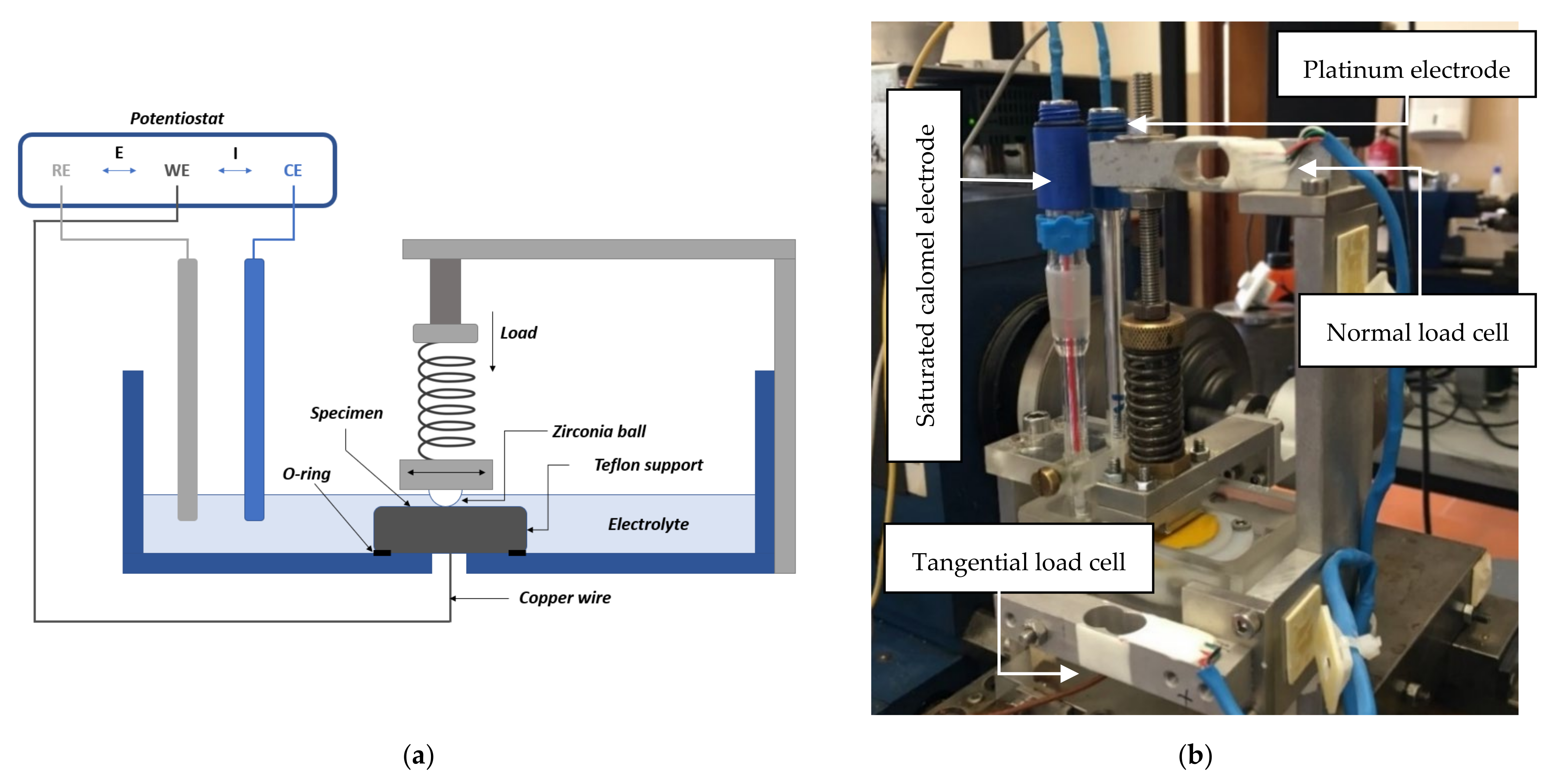
2.2. Triboelectrochemical Test

The wear–corrosion tests were conducted on an adapted homemade reciprocating sliding wear tester designed and built at our lab, as shown in Figure 3, using a 0.5 M NaCl + 0.05 M HCl solution as the corrosive medium.

2.2.1. Electrochemical Test

Electrochemical testing was performed in a 0.5 M NaCl + 0.05 M HCl corrosive medium, since this medium can be found in real applications in the oil and gas industry, with a standard three-electrode cell consisting of a working electrode (WE), reference electrode (RE), and a counter electrode (CE) as shown in the scheme of Figure 3a. The specimens were connected to an insulated copper wire using tin solder and, finally, mounted on cold-setting resin with a working area approximately delimited to 0.196 cm2 using insulating tape.
The different test specimens were placed on Teflon support and then coupled to the triboelectrochemical equipment. There is a small orifice on this apparatus to allow the passage of the insulated copper wire. To avoid electrolyte leakage, an O-ring was placed between the sample holder and the recipient. The reference electrode was a saturated calomel electrode (SCE), and the counter electrode was a platinum wire, as can be seen in Figure 3b.
The electrochemical measurements were carried out with an SP-50 Potentiostat from BioLogic Science Instruments, Seyssinet-Pariset, France. To evaluate the corrosion resistance of the different composites, potentiodynamic polarization curves (anodic sweeps) were obtained from near the open circuit potential (OCP) to +1.2 VSCE with a scan rate of 1 mV/s. To determine the corrosion potential (Ecorr) and corrosion current (icorr), Tafel extrapolation of the polarization curves was used. During the tribocorrosion measurements, the open circuit potential was monitored.

2.2.2. Tribological Test

The wear–corrosion tests were performed against a flat specimen using a zirconia ball, produced by Luis Aparicio SL, Barcelona, Spain, with a 10 mm diameter, a density of 6.05 g/cm3, and microhardness of 13 GPa. During the tests, a harmonic wave imposing a reciprocating movement to the ball was generated by an eccentric rod mechanism set designed at our lab with a stroke length of 2 mm and a frequency of 3 Hz. The sliding movement was conducted with contact loads of 17, 23, and 29 N and 0.012 m/s linear sliding speed. The tests were performed at room temperature (23 ± 2 °C) and 46 ± 10% relative humidity, and for each test, the zirconia ball and specimens were ultrasonically cleaned and dried.
As illustrated in Figure 3b, in this equipment, the normal load is directly applied to the upper specimen holder by a spindle spring system and is measured by a load cell. The lower specimen holder is supported by a tangential load cell, allowing the calculation of the friction force. The coefficient of friction (COF) was calculated using the normal and tangential forces (FT/FN) ratio. The test parameters used in the tribocorrosion experiments are summarized in Table 2. Three tests were performed for each specimen, corresponding to three different applied loads.
Taking into consideration the mechanical properties of the hardmetals tested (Table 1), the applied loads (17–29 N), and the geometry of the sphere-plan contact, it was possible to calculate, according to the Hertzian contact theory, the maximum contact pressure—varying between 1.48 and 1.82 GPa—and the semicontact width of 0.07–0.09 × 10⁻³ m. These test parameters were selected to have conditions close to those found in real applications and also to compare the results obtained with previous experiments carried out in dry conditions.
After the tribocorrosion test, the surface morphology and the wear mechanisms were examined by observing the worn surfaces with a scanning electron microscope (SEM—Hitachi-SU-3800, Hitachi, Japan) and an optical microscope (LEICA DM 2500, Leica, Germany) as well as a 3D profilometer Rodenstock RM 600 laser stylus from Rodenstock GmbH, Munich, Germany.

3. Results and Discussion

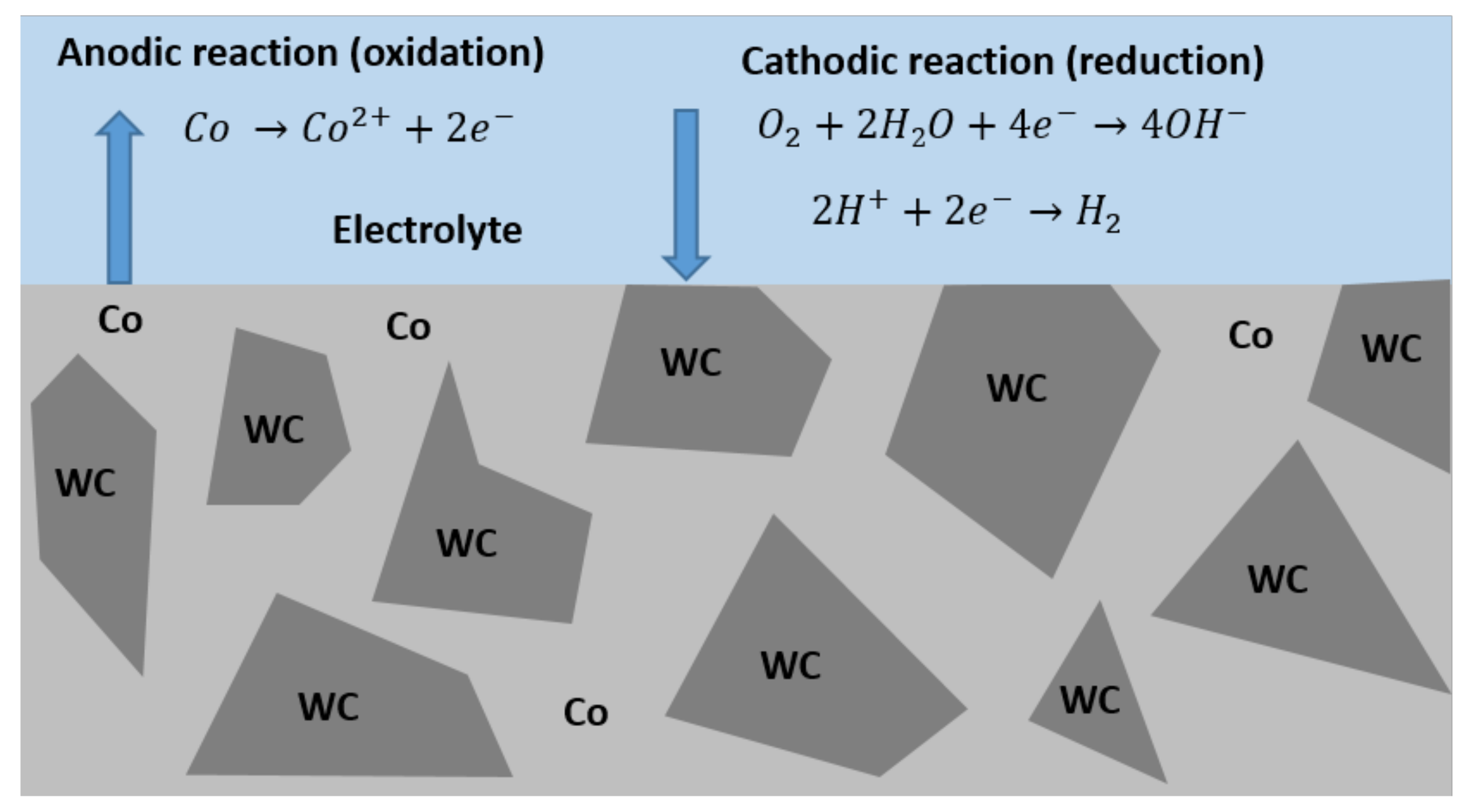
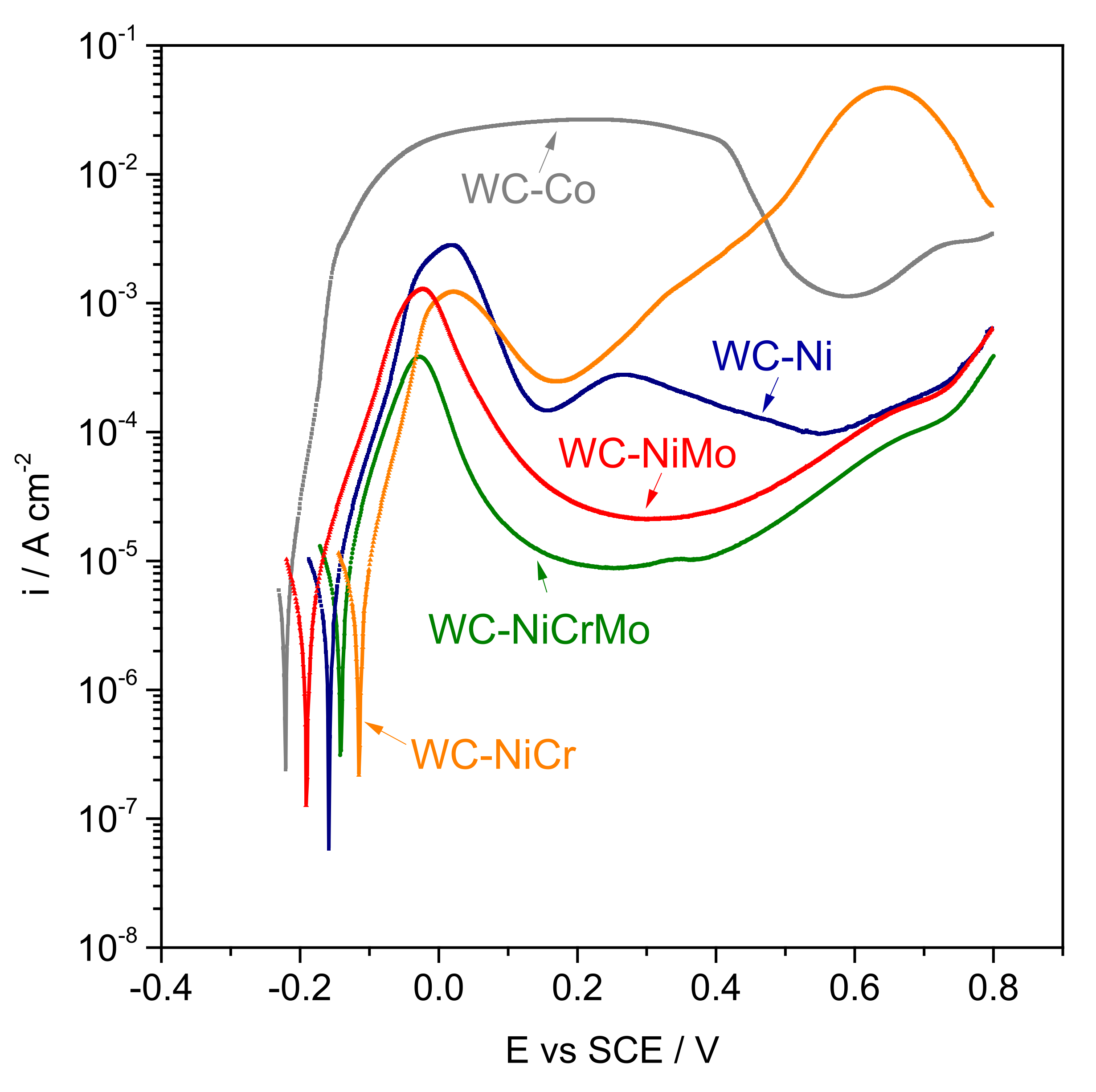
3.1. Electrochemical Behaviour

Figure 4 shows the polarization curves for all the composites tested (WC-Co, WC-Ni, WC-NiCr, WC-NiMo, and WC-NiCrMo). By analysing the curves presented in Figure 4 and the data in Table 3, where the Ecorr (corrosion potential) and icorr (corrosion current density) are summarized, it can be concluded that the corrosion potential for the WC-Co composite shifts to more negative values (−221.2 mVSCE) than for the Ni-based binder composites. WC-NiCr shifts to less negative values (−114.9 mVSCE), with the other composites assuming intermediate corrosion potential values. No significant differences were observed concerning the corrosion current densities, presenting values between 4.02 × 10⁻⁶ and 5.31 × 10⁻⁶ A/cm2, with WC-Co and WC-Ni showing higher corrosion currents.
The cathodic branches are not presented here since they are identical to all the specimens, showing a current increase caused by oxygen reduction. For more negative potentials, the current increases again due to the reduction of water with hydrogen evolution.
Analysing the anodic branches at the right side of the polarization curves, it is possible to conclude that the WC-Co specimen presented a completely different behaviour than the other Ni-based binder composites (WC-Ni, WC-NiCr, WC-NiMo, and WC-NiCrMo). For the WC-Co specimen, a small anodic overpotential was sufficient to produce a noticeable increase in the current density, followed by a large passive region close to the corrosion potential. Regarding Ni-based binder composites, larger overpotentials had to be applied to reach similar current densities. Furthermore, as the potential increases, there is an increase in current up to 0.0 VSCE due to the binder dissolution. For potentials of the order of −0.15 VSCE, a Ni oxide protective film is formed, as can be deduced by the small plateaus. There is a rupture of the film for more positive potentials due to the chloride ions in the solution, and an increase in current is observed. For potentials of 0.50 to 0.7 VSCE, a second plateau is observed, mainly for the WC-Ni specimen, except for the WC-NiCr specimen. This second plateau is related to the formation of tungsten oxides [30].
Figure 5 illustrates the evolution of the open circuit potential for the WC-NiCr specimen before, during, and after the tribological test. Before the tribological test, the sample was immersed for 1 h, the potential was monitored, and no significant differences were detected.
Three regimes are easily identifiable. Once the test started, a significant drop in potential, known as cathodic shift, was observed. During the trial, fluctuations in the potential were registered, possibly due to the constant breakdown and formation of the protective oxide covering the WC grains. Finally, when the sliding stopped, the potential increased again, suggesting repassivation of the worn area.
Similar behaviour was registered for the remaining composites despite significant potential fluctuations in some cases. This may be attributed to the galvanic couple characteristic of the WC-based composites, in which WC grains act as the cathode and the binder as the anode.

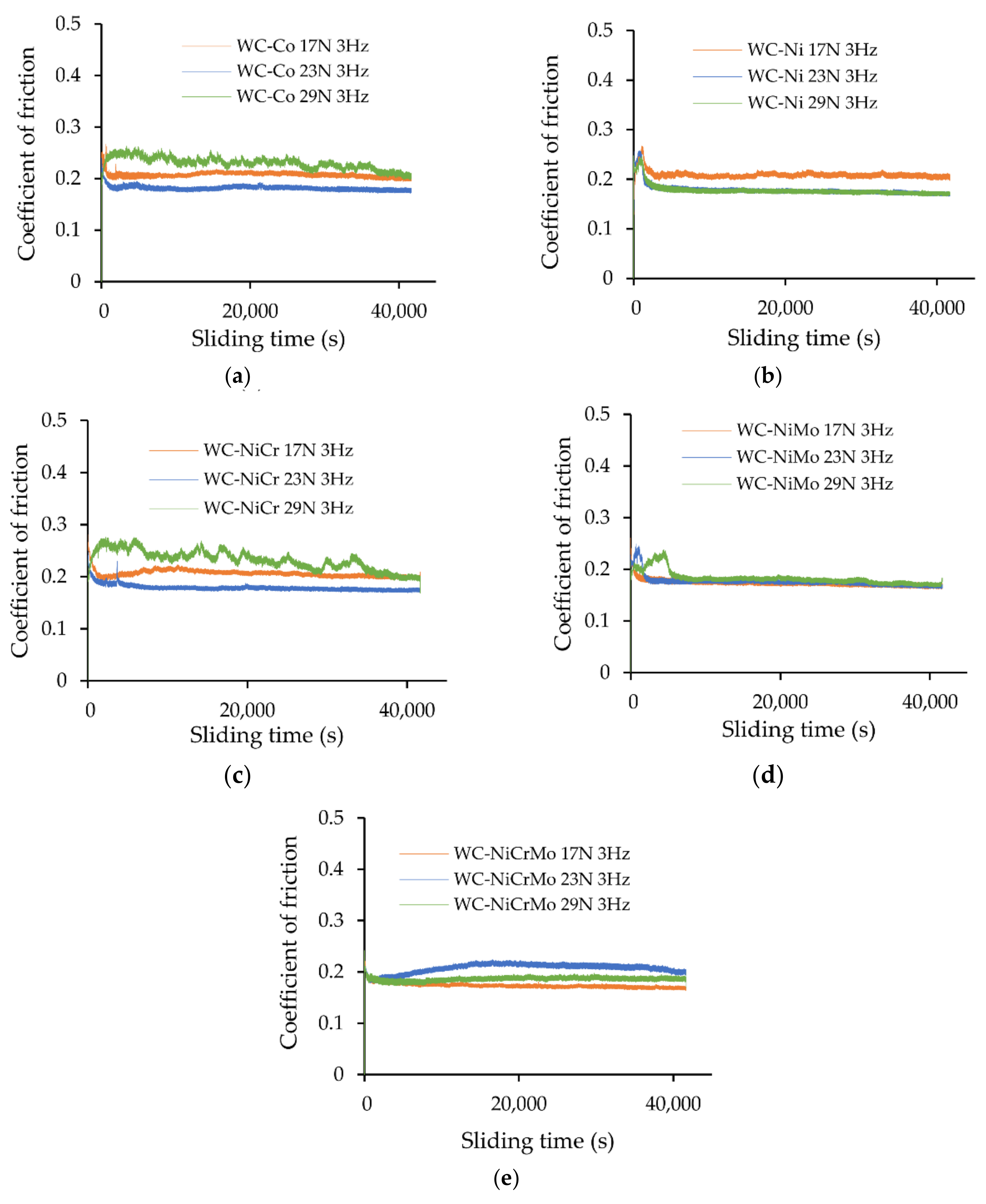
3.2. Friction Behaviour

Figure 6 shows the evolution of the coefficient of friction (COF) with the sliding time for the specimens tested rubbing against a zirconia ball under different loads (17, 23, and 29 N) and a frequency of 3 Hz in a 0.5 M NaCl + 0.05 M HCl corrosive medium. Almost no running-in was observed for most tribological systems, with the different systems reaching a steady state very quickly. The influence of the load was insignificant since the coefficient of friction values were of the same order for all the various test conditions, varying between 0.18 and 0.23. However, the curves obtained for the higher applied load of 29 N showed higher fluctuations in coefficient of friction, mainly for the WC-Co and WC-NiCr specimens (green curves of Figure 6a,c, respectively).
For the WC-Ni specimen (Figure 6b), a small running-in was observed regardless of the applied load, with the time to reach the steady state being less than 2500 s. Furthermore, the WC-NiMo specimen (Figure 6e) also presents a short running-in period for the applied load of 23 N and 29 N with 1700 and 5200 s, respectively.
Figure 7 presents the steady state coefficient of friction for the different specimens under dry (unlubricated) and in the presence of corrosive media (lubricated) conditions for an applied load of 23 N and 3 Hz frequency. The previous tests under dry sliding did not include the WC-NiMo specimen. It is observable that the coefficient of friction registered using an acidic electrolyte solution (lubricated conditions) is much lower than in dry conditions (unlubricated). For all specimens, the COF varies between 0.18 and 0.21 in an acidic electrolyte solution, while under dry conditions, the COF varies between 0.30 and 0.33.

3.3. Wear Behaviour

A laser profilometer was used to obtain 2D and 3D profiles of the worn surfaces to assess the wear volume of the different specimens.
Figure 8 shows the wear track for the WC-Co specimen rubbing against a zirconia ball under a 17 N normal load and 3 Hz frequency in a 0.5 M NaCl + 0.05 M HCl corrosive medium (lubricated conditions). It is possible to observe that the wear track has an inhomogeneous path, with greater width at the extremities than at the centre in a “dog bone shape” format. This is most likely due to a hydrodynamic effect, with the width being greater in zones where the sliding speed is null and smaller where the sliding speed is higher.
Figure 9 shows the results of the wear track, obtained in a previous study, for the WC-Co specimen rubbing with the same contact conditions but under dry sliding conditions. It can be seen that the shape of the wear track assumes an entirely different and homogeneous geometry, contrary to what was observed in the presence of the corrosive medium. In this dry situation, where the wear mechanism is essentially abrasive with considerable material removal, it is easier to quantify the wear rate by integrating the entire volume.
Figure 10 and Figure 11 show 2D profiles of the worn surfaces of the different specimens rubbing against a zirconia ball under a 17 N normal load in a 0.5 M NaCl + 0.05 M HCl solution (lubricated conditions). The 2D profiles were taken in the parallel (Figure 10) and perpendicular (Figure 11) directions to the sliding movement.
As shown in Figure 10, the wear track is barely visible, with only minor depth fluctuations registered for WC-Ni, WC-NiM,o and WC-NiCrMo specimens. On the other hand, as described above, for the WC-Co and WC-NiCr specimens, wear can be observed in higher depth at the ends of the wear track.
This agrees with the results presented above in Figure 6 and Figure 7. The presence of the corrosive medium contributes to a decrease in friction coefficient; consequently, volume losses are barely observed and difficult to quantify. Thus, due to the load support promoted by the hydrodynamic effect, the corrosive medium mainly contributes to lubricating the contact.

3.4. Wear Mechanisms

SEM micrographs from the wear tracks after the tribocorrosion tests of WC-Co, WC-Ni, WC-NiCr, WC-NiMo, and WC-NiCrMo specimens can be seen in Figure 12. The left column shows SEM micrographs with lower magnification, in which the entire wear track can be observed, while the right column shows higher-magnification SEM micrographs, in which it is possible to identify some of the wear mechanisms involved and observe the WC grains.
In general, the wear was caused by the preferential removal and dissolution of the binder around the carbide grains. This preferential removal of the binder leads to a “gap” around the carbide grains, which increases due to the combined action of corrosion and abrasion, resulting in the pull-out of undermined WC particles and the formation of erosive pits. On the other hand, there are localized areas where the microstructure of the composite was almost unaffected, with the WC grains remaining practically intact in the binder matrix.
Figure 13 shows an SEM-EDS mapping for the WC-Co specimen after the tribocorrosion test under a 17 N normal load, 41,667 s sliding time, and 3 Hz frequency in an acidic solution of 0.5 M NaCl + 0.05 M HCl. It is possible to observe that an oxide layer was preferentially formed at the specific zones where the binder dissolution and/or binder removal occurred. Most likely, after the removal/dissolution of the binder, the WC grains underwent an oxidation process [30,31], as evidenced by the intense red colour in the eroded region shown in Figure 13a,c. Thus, the formation of these W oxides could also reduce the wear on samples’ surfaces.
The tribocorrosion behaviour of cemented carbides has been studied at the laboratory scale using different techniques. Engqvist et al. [26] used a conventional pin-on-disc apparatus and varied the pH media between 1 and 14. It was verified that the samples in contact with acidic solutions presented an etched surface with binder dissolution. On the contrary, they found that WC grains were markedly corroded in alkaline solutions. Thus, the wear rate increases with pH, and the deterioration of the WC grains was the main cause of this effect. By performing scratch experiments, Gee et al. [32] also verified that the degradation mechanisms are accelerated in an acidic environment. The authors observed the Co binder dissolution up to 5 µm below the scratch contributing to the instability of the WC grains.
Gant et al. [27] also studied different WC-Co grades in a corrosive environment, varying pH between 1.1 and 13. Contrary to what Engqvist et al. [26] reported, the authors found that immersion in more acidic media promotes the binder removal and the pull-out of small WC grains. They also mention that the wear rate decreases in more alkaline media. Furthermore, they also evidenced that the microstructure plays a more critical role than the bulk material properties on wear resistance, reinforcing that the wear mechanisms are essential in studying these systems. SEM analyses revealed that in acidic media, hard metals with coarser carbide grains show a lower wear volume. WC grains remain in situ rather than being removed by abrasive processes.
Additionally, it should be noted that the corrosion resulting from the binder removal has a marked impact on the material’s mechanical properties. Tarragó et al. [33] detected a significant decrease in the strength of WC-Co composites after exposure to acidic solutions. In addition to the removal of the binder, these authors also observed heterogeneous corrosion that promotes the creation of stresses inside the corrosion pits.
Based on the studies that have been carried out, the microstructure and the composition of the cemented carbides are two crucial factors that significantly affect their wear behaviour. Regardless of the wear mechanism, material loss occurs typically due to cutting processes and the fracture and pull-out of WC grains due to the absence of the binder. These phenomena were observed in all the specimens tested. Co, the most common binder, is vulnerable to abrasion and erosion and has low corrosion resistance, as observed in the respective polarization curve shown in Figure 4. Consequently, preferential dissolution of the binder occurs, reducing the material’s capacity to absorb energy, i.e., the fracture toughness.
Furthermore, WC grains are unsupported and fracture more readily or can be removed/pulled out. The micrographs shown in Figure 12 corroborate this behaviour. Notably, the WC-Co composite (Figure 12a,b) has a more damaged surface than the remaining Ni-based hardmetals.
Tribocorrosion systems turn out to be quite complex since there are several variables to control. In this way, it is possible to infer that a material optimized for a specific degradation mechanism may not be equally optimal when exposed to both processes. For example, Ni can be a good choice for applications where high corrosion resistance (static) is required. However, in a tribocorrosive system, its passive layer is no longer effective, or its intrinsic mechanical properties are inferior to Co. Therefore, understanding all these factors is the key to selecting the most suitable hardmetal composition for a given application.

4. Conclusions

  • Regarding corrosion resistance in 0.5 M NaCl + 0.05 M HCl acidic medium, Ni-based hard metals (WC-Ni, WC-NiCr, WC-NiMo, and WC-NiCrMo) presented similar corrosion behaviour, but the corrosion resistance of WC-NiCr and WC-NiCrMo is slightly higher. WC-Co presented the lowest corrosion resistance.
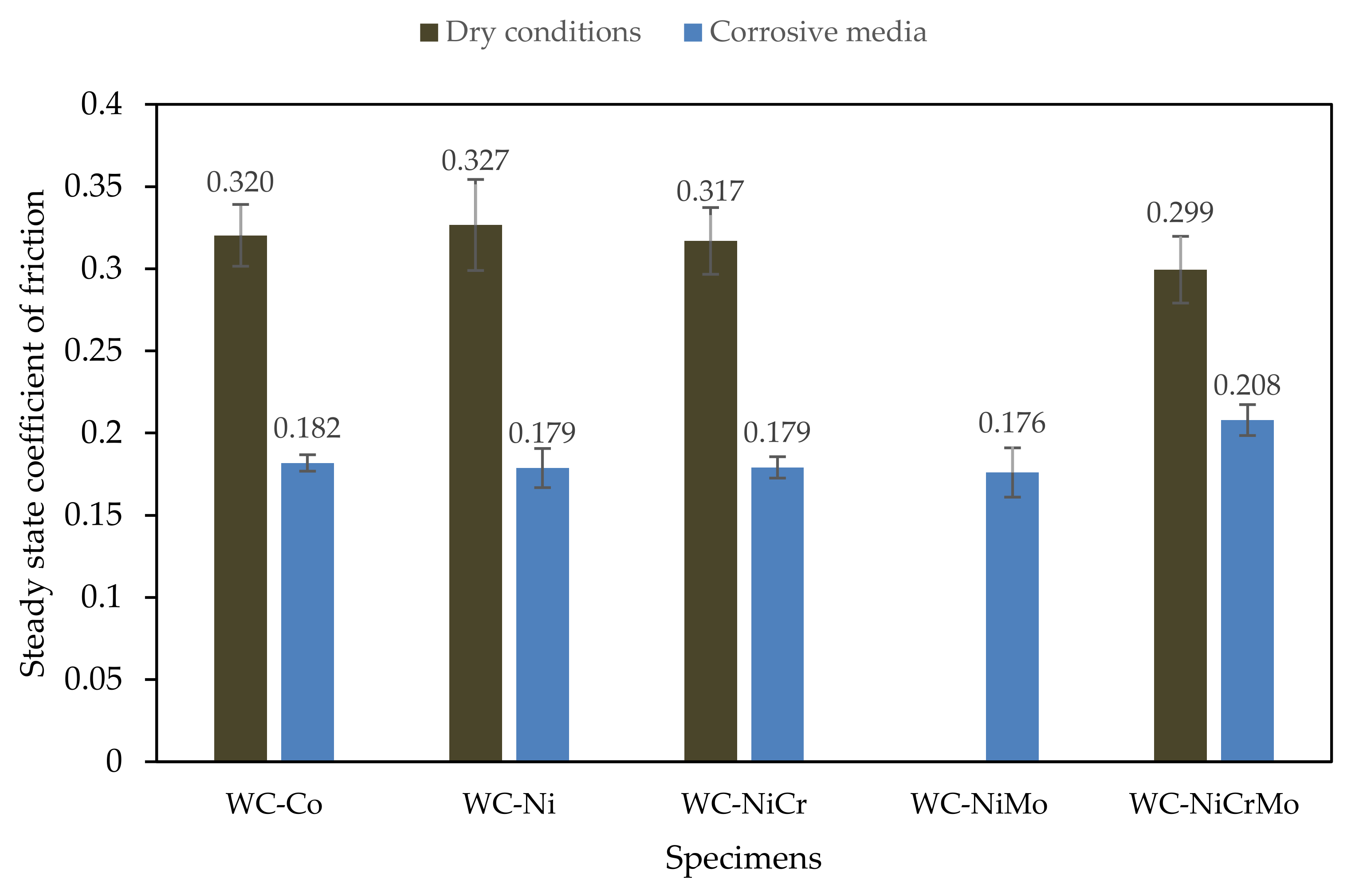
  • For all the specimens investigated in the presence of the corrosive medium (lubricated conditions), the steady state coefficient of friction varied between 0.18 and 0.21. Comparison with previous results under dry conditions showed higher coefficients of friction by a factor of approximately two times (0.30 to 0.33).
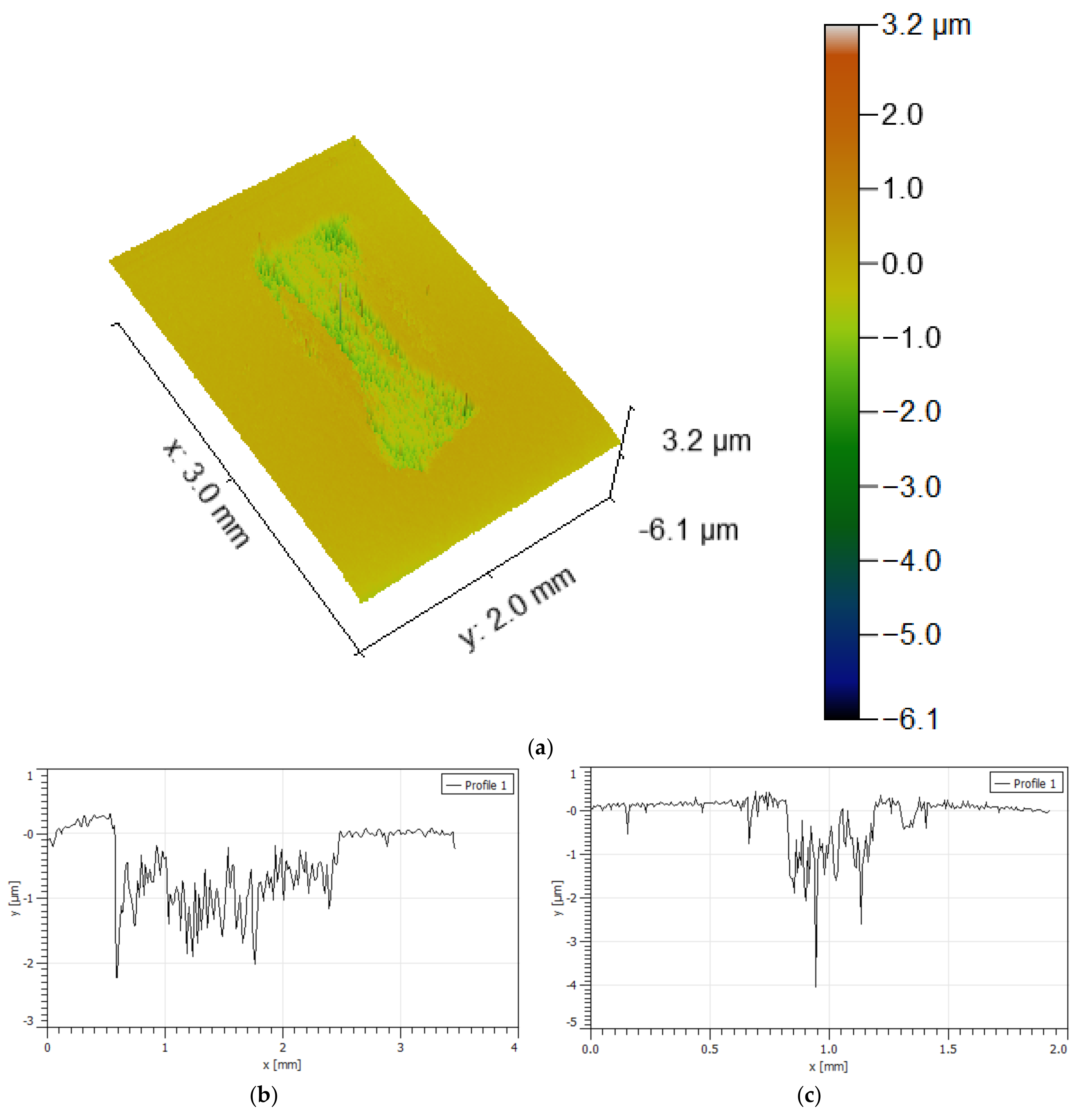
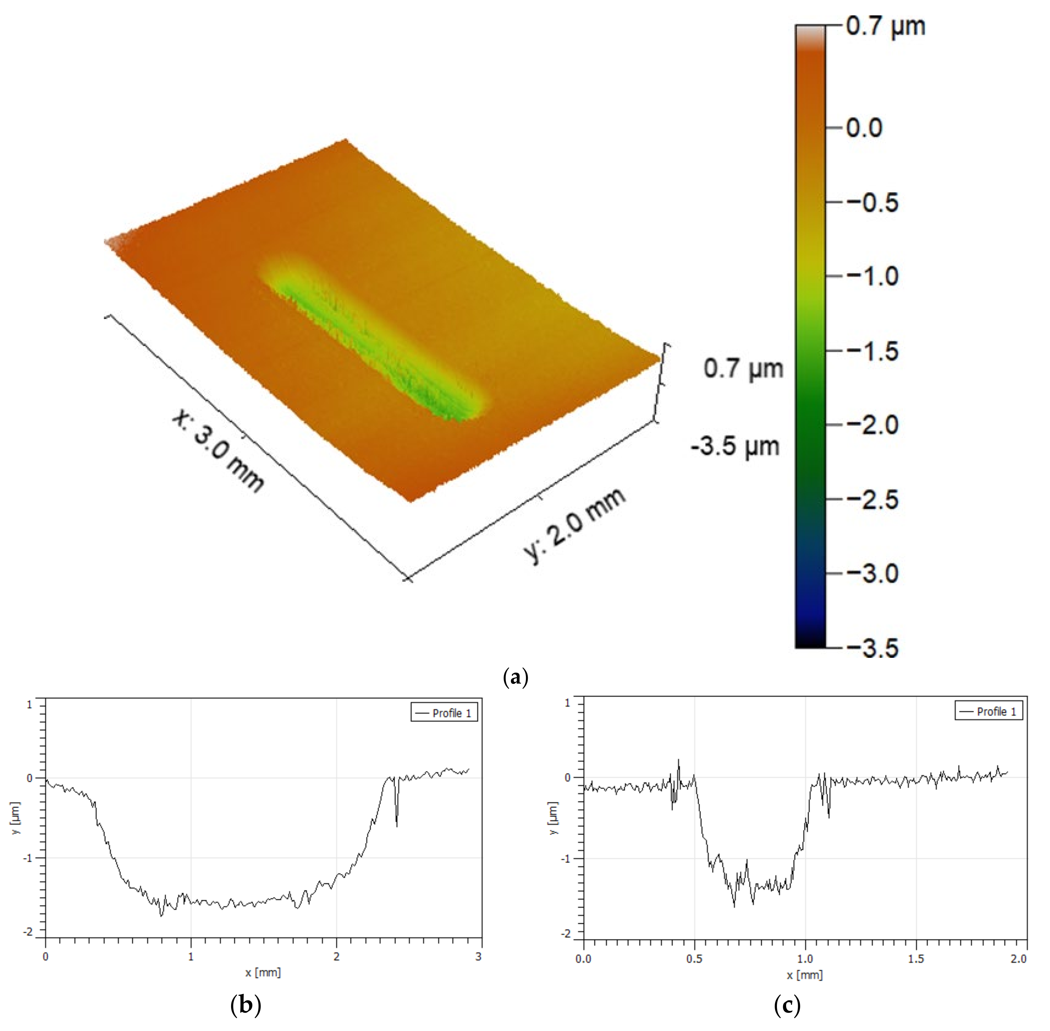
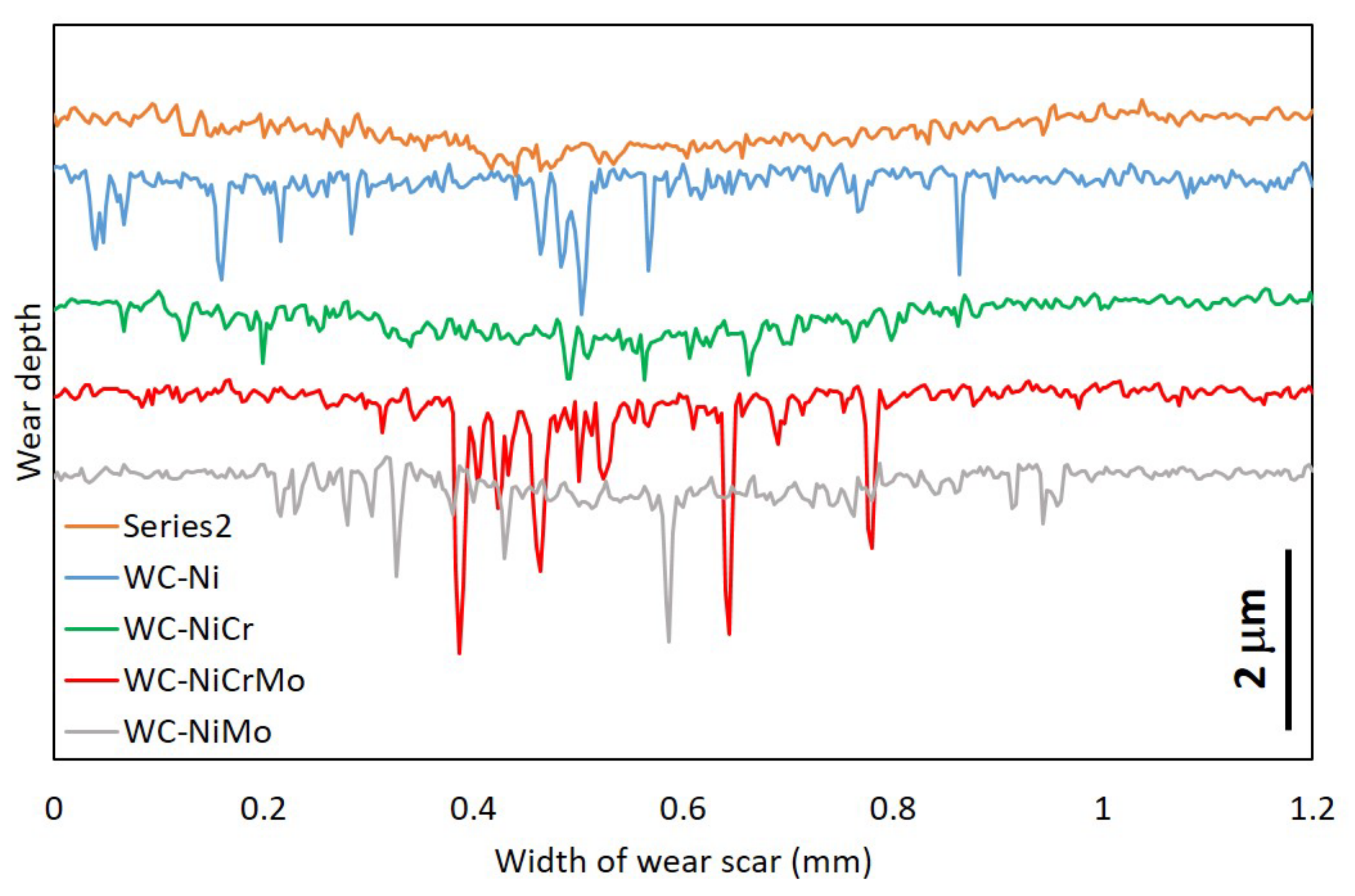
  • The wear rate was difficult to estimate since the wear track, for most of the specimens analysed, presented a “dog bone shape”, revealing a hydrodynamic effect, with the visible wear being more significant in zones where the sliding speed is null (extremities of the wear track) and smaller where the sliding speed is higher (in the middle of the wear track). Due to the lubricating effect, they showed much lower wear than in dry sliding tests.
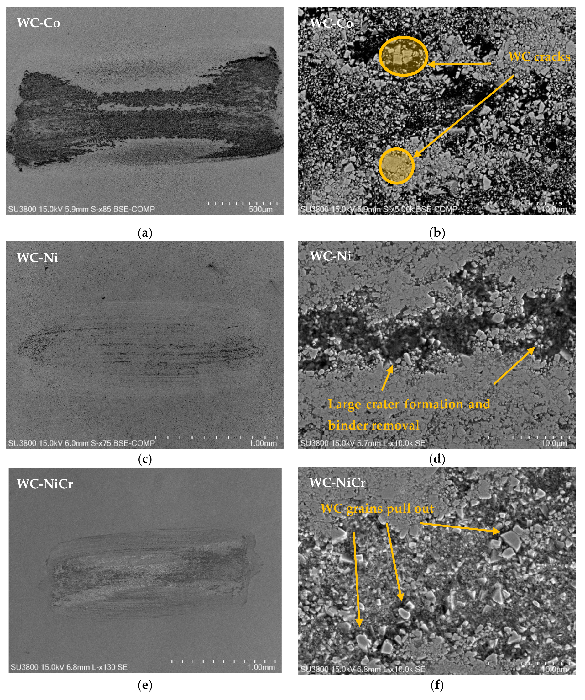
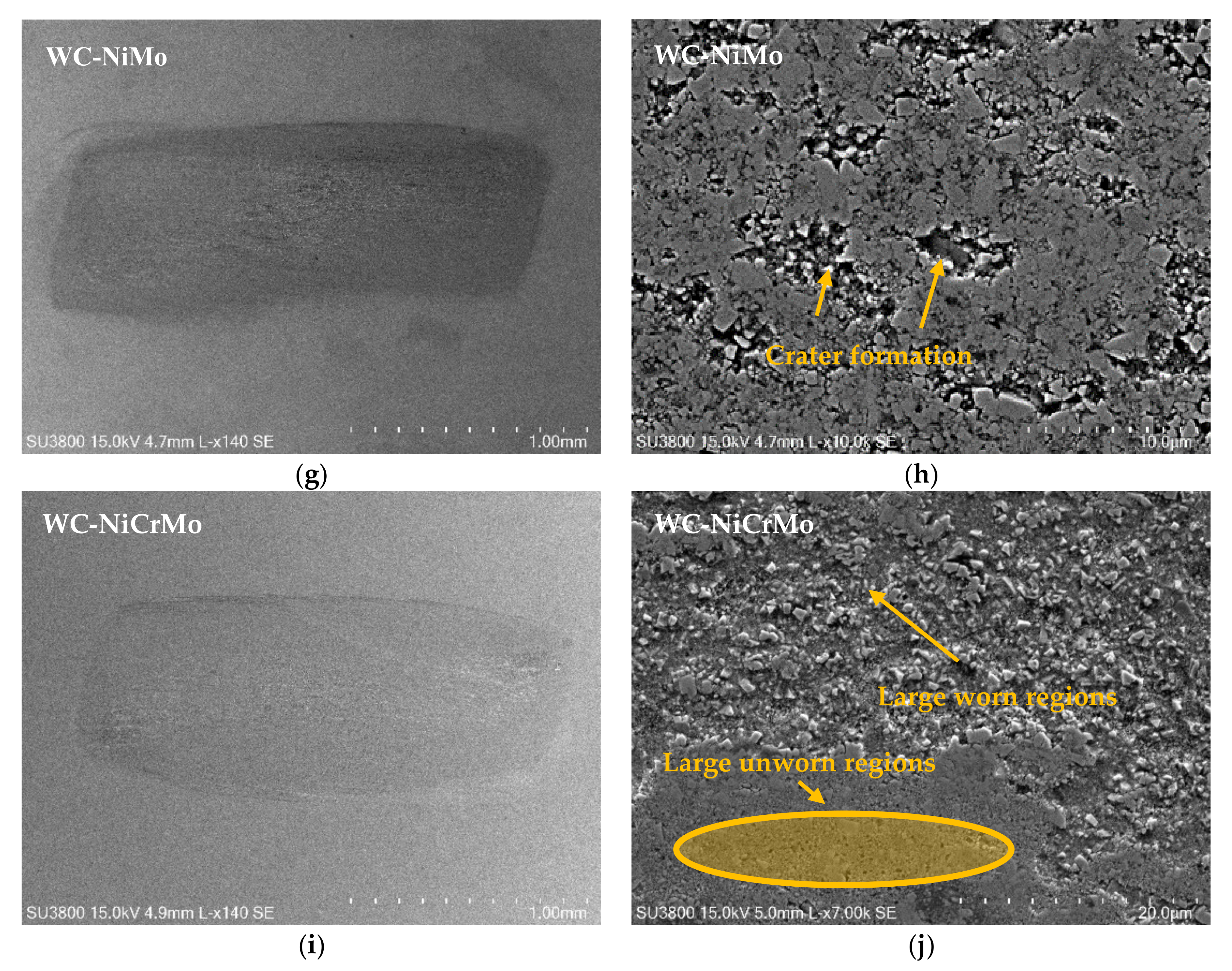
  • Wear mechanisms include binder removal, large cratering formation, and carbide grain pull-out, creating vast eroded regions.
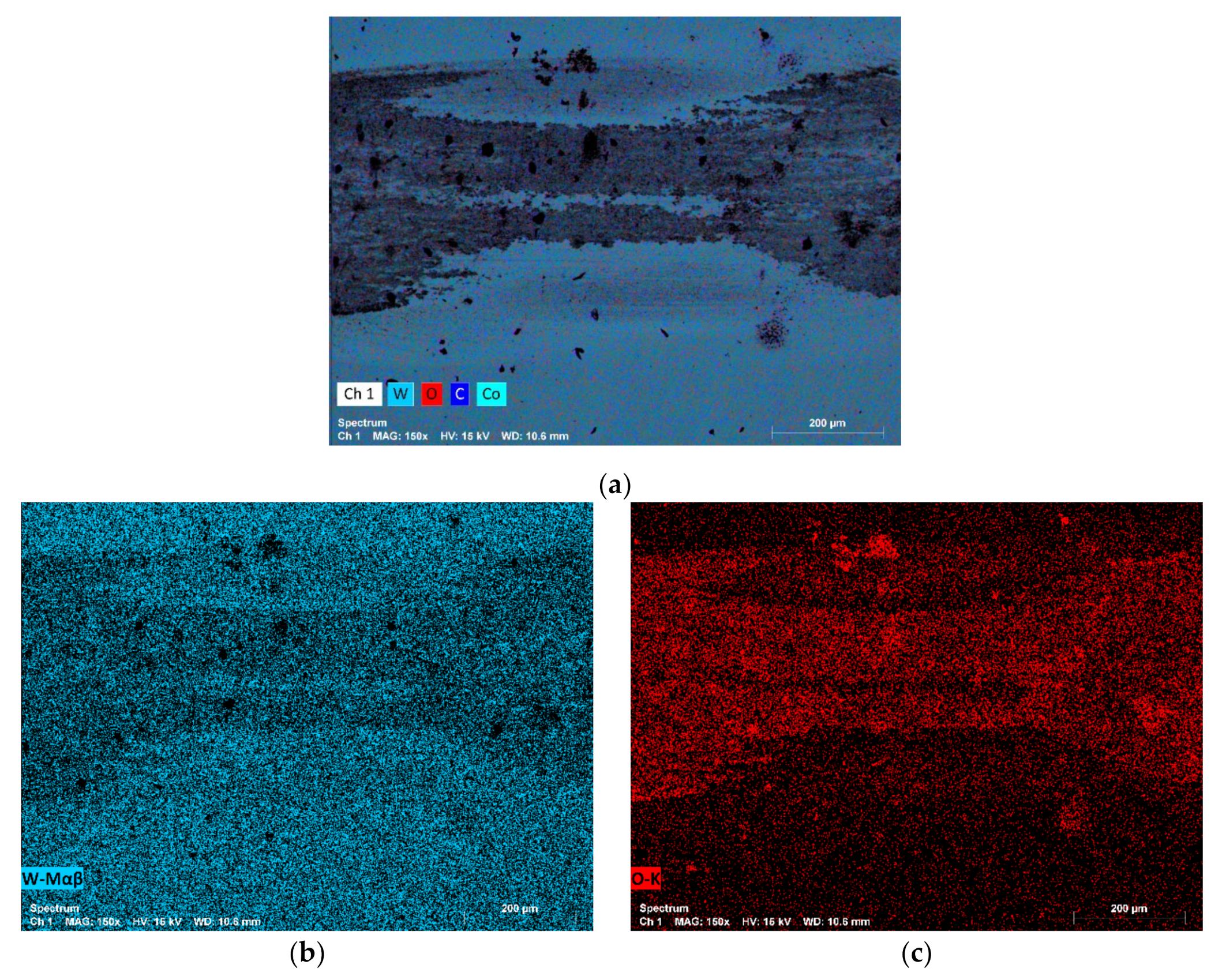
  • A synergistic effect between wear and corrosion for the contact conditions employed was not verified since the electrolyte contributed mainly to lubricating the contact, reducing friction and wear, and not accelerating wear and corrosion due to load support promoted by hydrodynamic effect and W oxide films formed on the specimen’s surface.
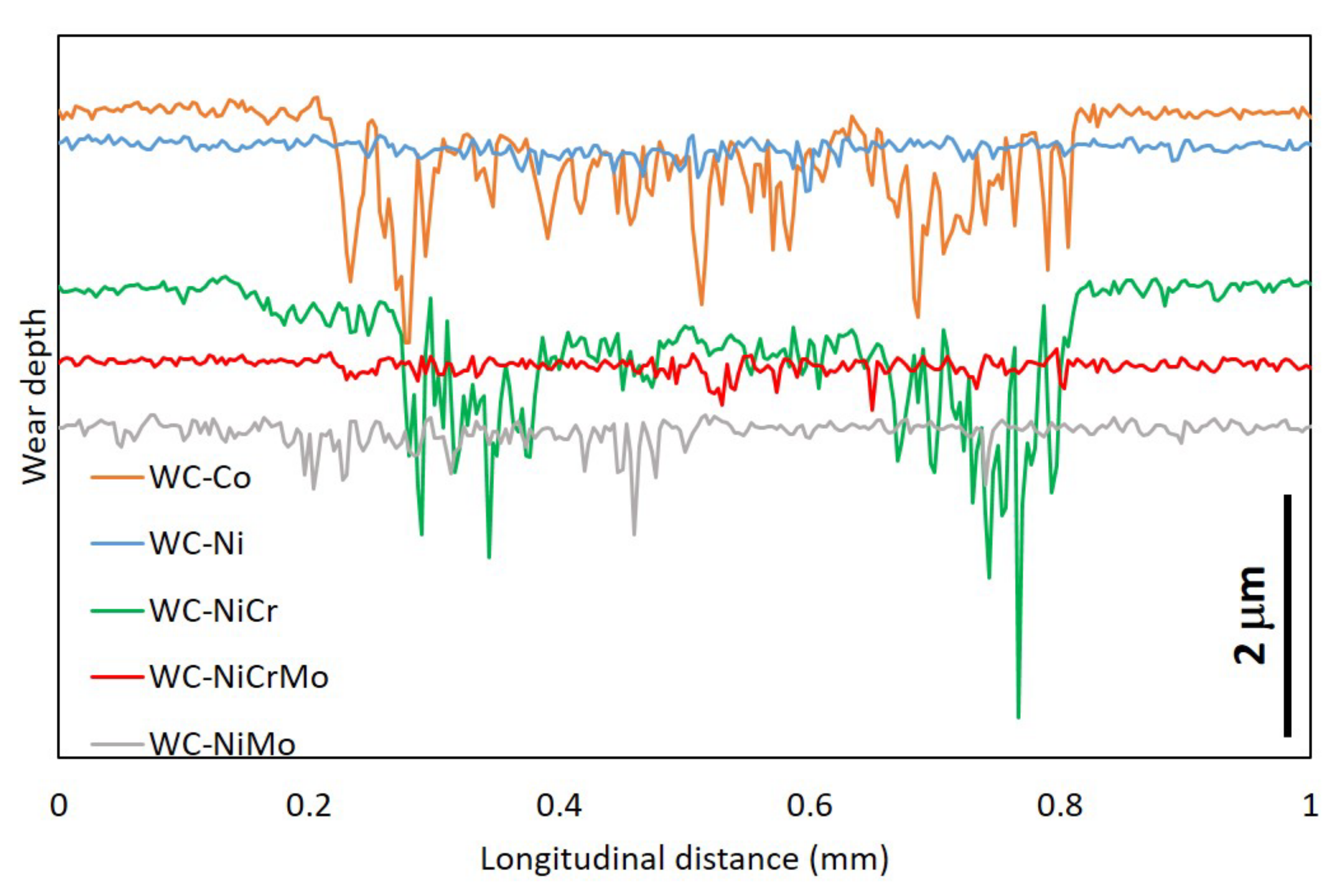
  • The specimens that presented higher wear were the WC-Co and WC-NiCr composites showing large portions of worn surfaces, while WC-Ni, WC-NiMo, and WC-NiCrMo showed some confined wear with localized craters.

Author Contributions

Conceptualization, P.P.; methodology, P.P. and L.V.; validation, L.V. and A.R; formal analysis, P.P., L.V. and A.R.; investigation, P.P. and L.V.; data curation, P.P. and L.V.; writing—original draft preparation, P.P. and L.V.; writing—review and editing, J.S., A.S., L.M. and A.R.; visualization, P.P.; supervision, A.R., J.S., A.S. and L.M. All authors have read and agreed to the published version of the manuscript.

Funding

P. Pereira acknowledges FCT for financial support (SFRH/BD/138040/2018). This work was developed within the scope of the project CICECO-Aveiro Institute of Materials, UIDB/50011/2020, UIDP/50011/2020 & LA/P/0006/2020, financed by national funds through the FCT/MEC (PIDDAC). Furthermore, we acknowledge HARDTECH–POCI–01-0247-FEDER-045283, financed by FEDER under the PT2020 Partnership Agreement. This research was sponsored by national funds through FCT–Fundação para a Ciência e a Tecnologia under the project UIDB/00285/2020.

Institutional Review Board Statement

Not applicable.

Informed Consent Statement

Not applicable.

Data Availability Statement

The data presented in this study are available on request from the corresponding author. The data are not publicly available due to privacy.

Conflicts of Interest

The authors Amílcar Ramalho, Luís Vilhena, Ana Senos, and Luís Filipe Malheiros declare no conflict of interest. The authors P. Pereira and J. Sacramento declare financial interests/personal relationships that may be considered potential competing interests: author P. Pereira collaborates with the company DURIT and DURIT employs J. Sacramento.

References

  1. ASTM. Standard Terminology Relating to Wear and Erosion G40-17; ASTM International: West Conshohocken, PA, USA, 2017. [Google Scholar]
  2. López-Ortega, A.; Arana, J.L.; Bayón, R. Tribocorrosion of Passive Materials: A Review on Test Procedures and Standards. Int. J. Corros. 2018, 2018, 7345346. [Google Scholar] [CrossRef]
  3. Landolt, D.; Mischler, S.; Stemp, M. Electrochemical methods in tribocorrosion: A critical appraisal. Electrochim. Acta 2001, 46, 3913–3929. [Google Scholar] [CrossRef]
  4. Mischler, S. Triboelectrochemical techniques and interpretation methods in tribocorrosion: A comparative evaluation. Tribol. Int. 2008, 41, 573–583. [Google Scholar] [CrossRef]
  5. Diomidis, N.; Celis, J.-P.; Ponthiaux, P.; Wenger, F. A methodology for the assessment of the tribocorrosion of passivating metallic materials. Lubr. Sci. 2009, 21, 53–67. [Google Scholar] [CrossRef]
  6. Trezona, R.; Allsopp, D.; Hutchings, I. Transitions between two-body and three-body abrasive wear: Influence of test conditions in the microscale abrasive wear test. Wear 1999, 225–229, 205–214. [Google Scholar] [CrossRef]
  7. Landolt, D.; Mischler, S.; Stemp, M.; Barril, S. Third body effects and material fluxes in tribocorrosion systems involving a sliding contact. Wear 2004, 256, 517–524. [Google Scholar] [CrossRef]
  8. Diomidis, N.; Mischler, S. Third body effects on friction and wear during fretting of steel contacts. Tribol. Int. 2011, 44, 1452–1460. [Google Scholar] [CrossRef]
  9. Landolt, D.; Mischler, S. Tribocorrosion of Passive Metals and Coatings; Elsevier: Amsterdam, The Netherlands, 2011. [Google Scholar]
  10. Stachowiak, G.; Salasi, M.; Stachowiak, G. Three-body abrasion corrosion studies of high-Cr Cast irons: Benefits and limi-tations of tribo-electrochemical methods. J. Bio- Tribo-Corros. 2015, 1, 6. [Google Scholar] [CrossRef]
  11. Landolt, D. Electrochemical and materials aspects of tribocorrosion systems. J. Phys. D: Appl. Phys. 2006, 39, 3121–3127. [Google Scholar] [CrossRef]
  12. Mathew, M.; Pai, P.S.; Pourzal, R.; Fischer, A.; Wimmer, M.A. Significance of Tribocorrosion in Biomedical Applications: Overview and Current Status. Adv. Tribol. 2009, 2009, 250986. [Google Scholar] [CrossRef] [Green Version]
  13. Kasar, A.K.; Siddaiah, A.; Ramachandran, R.; Menezes, P.L. Tribocorrosion Performance of Tool Steel for Rock Drilling Process. J. Bio. Tribo-Corros. 2019, 5, 44. [Google Scholar] [CrossRef]
  14. Katiyar, P.K. A comprehensive review on synergy effect between corrosion and wear of cemented tungsten carbide tool bits: A mechanistic approach. Int. J. Refract. Met. Hard Mater. 2020, 92, 105315. [Google Scholar] [CrossRef]
  15. Weidow, J.; Andrén, H.-O. Grain and phase boundary segregation in WC–Co with TiC, ZrC, NbC or TaC additions. Int. J. Refract. Hard Met. 2011, 29, 38–43. [Google Scholar] [CrossRef]
  16. Berg, G.; Friedrich, C.; Broszeit, E.; Berger, C.; Riedel, R. Handbook of Ceramic Hard Materials; Wiley-VCH Weinheim: Weinheim, Germany, 2000. [Google Scholar]
  17. Beste, U.; Hartzell, T.; Engqvist, H.; Axén, N. Surface damage on cemented carbide rock-drill buttons. Wear 2001, 249, 324–329. [Google Scholar] [CrossRef]
  18. Beste, U.; Jacobson, S. Friction between a cemented carbide rock drill button and different rock types. Wear 2002, 253, 1219–1221. [Google Scholar] [CrossRef]
  19. Human, A.; Roebuck, B.; Exner, H. Electrochemical polarisation and corrosion behaviour of cobalt and Co (W, C) alloys in 1 N sulphuric acid. Mater. Sci. Eng. A 1998, 241, 202–210. [Google Scholar] [CrossRef]
  20. Scholl, H.; Hofman, B.; Rauscher, A. Anodic polarization of cemented carbides of the type [(WC, M): M = Fe, Ni or Co] in sulphuric acid solution. Electrochim. Acta 1992, 37, 447–452. [Google Scholar] [CrossRef]
  21. Sutthiruangwong, S.; Mori, G.; Kösters, R. Passivity and pseudopassivity of cemented carbides. Int. J. Refract. Met. Hard Mater. 2005, 23, 129–136. [Google Scholar] [CrossRef]
  22. Rocha, A.F.; Bastos, A.; Cardoso, J.P.V.; Rodrigues, F.; Fernandes, C.M.S.; Soares, E.; Sacramento, J.; Senos, A.; Ferreira, M. Corrosion behaviour of WC hardmetals with nickel-based binders. Corros. Sci. 2018, 147, 384–393. [Google Scholar] [CrossRef]
  23. Gant, A.; Gee, M.; Gohil, D.; Jones, H.; Orkney, L. Use of FIB/SEM to assess the tribo-corrosion of WC/Co hardmetals in model single point abrasion experiments. Tribol. Int. 2013, 68, 56–66. [Google Scholar] [CrossRef]
  24. Larsen-Basse, J. Wear of Hard-Metals in Rock Drilling: A Survey Of The Literature. Powder Met. 1973, 16, 1–32. [Google Scholar] [CrossRef]
  25. Wentzel, E.; Allen, C. The erosion-corrosion resistance of tungsten-carbide hard metals. Int. J. Refract. Met. Hard Mater. 1997, 15, 81–87. [Google Scholar] [CrossRef]
  26. Engqvist, H.; Beste, U.; Axén, N. The influence of pH on sliding wear of WC-based materials. Int. J. Refract. Met. Hard Mater. 2000, 18, 103–109. [Google Scholar] [CrossRef]
  27. Gant, A.; Gee, M.; May, A. Microabrasion of WC–Co hardmetals in corrosive media. Wear 2004, 256, 954–962. [Google Scholar] [CrossRef]
  28. Pereira, P.; Vilhena, L.; Sacramento, J.; Senos, A.; Malheiros, L.; Ramalho, A. Abrasive wear resistance of WC-based com-posites, produced with Co or Ni-rich binders. Wear 2021, 482, 203924. [Google Scholar] [CrossRef]
  29. Vilhena, L.M.; Fernandes, C.M.; Soares, E.; Sacramento, J.; Senos, A.M.R.; Ramalho, A. Abrasive wear resistance of WC–Co and WC–AISI 304 composites by ball-cratering method. Wear 2016, 346–347, 99–107. [Google Scholar] [CrossRef]
  30. Tomlinson, W.J.; Linzell, C.R. Anodic polarization and corrosion of cemented carbides with cobalt and nickel binders. J. Mater. Sci. 1988, 23, 914–918. [Google Scholar] [CrossRef]
  31. Tomlinson, W.; Molyneux, I. Corrosion, erosion-corrosion, and the flexural strength of WC-Co hardmetals. J. Mater. Sci. 1991, 26, 1605–1608. [Google Scholar] [CrossRef]
  32. Gee, M. Model scratch corrosion studies for WC/Co hardmetals. Wear 2010, 268, 1170–1177. [Google Scholar] [CrossRef]
  33. Tarragó, J.M.; Fargas, G.; Jimenez-Pique, E.; Felip, A.; Isern, L.; Coureaux, D.; Roa, J.J.; Al-Dawery, I.; Fair, J.; Llanes, L.; et al. Corrosion damage in WC–Co cemented carbides: Residual strength assessment and 3D FIB-FESEM tomography characterisation. Powder Met. 2014, 57, 324–330. [Google Scholar] [CrossRef]
Figure 1. Scheme representative of the behaviour of the WC-Co composite in an electrolyte solution, acting as a micro galvanic couple.
Lubricants 10 00145 g001
Figure 2. SEM micrographs of the different specimens before being subjected to the tribological tests: (a) WC-Co, (b) WC-Ni, (c) WC-NiCr, (d) WC-NiMo, and (e) WC-NiCrMo.
Lubricants 10 00145 g002aLubricants 10 00145 g002b
Figure 3. Triboelectrochemical apparatus: (a) schematic electrochemical circuit showing the working electrode, the reference electrode, and the counter electrode and (b) homemade cell, showing the load cells, the saturated calomel electrode, and the platinum electrode.
Lubricants 10 00145 g003
Figure 4. Potentiodynamic polarization curves for the five different WC-based composites in 0.5 M NaCl + 0.05 M HCl (scan rate = 1 mV/s).
Lubricants 10 00145 g004
Figure 5. Evolution of the open circuit potential (OCP) for the WC-NiCr specimen before, during, and after the tribological test for a 17 N normal load and 3 Hz frequency.
Lubricants 10 00145 g005
Figure 6. Evolution of the coefficient of friction (COF) with the sliding time for tested specimens rubbing against the zirconia ball with different applied loads (17, 23, and 29 N) and frequency of 3 Hz in a 0.5 M NaCl + 0.05 M HCl solution (lubricated conditions): (a) WC-Co, (b) WC-Ni, (c) WC-NiCr, (d) WC-NiMo, and (e) WC-NiCrMo.
Lubricants 10 00145 g006
Figure 7. Steady state coefficient of friction values for the four specimens (WC-Co, WC-Ni, WC-NiCr, WC-NiMo, and WC-NiCrMo) for a normal load of 23 N in dry/unlubricated and in the presence of the corrosive media/lubricated conditions.
Lubricants 10 00145 g007
Figure 8. Profiles of the wear track for the WC-Co specimen rubbing against a zirconia ball in a 0.5 M NaCl + 0.05 M HCl solution (lubricated), the severity of 8500 N.m and 3 Hz of frequency: (a) 3D profile, (b) longitudinal profile, and (c) transversal profile.
Lubricants 10 00145 g008
Figure 9. Profiles of the wear track for the WC-Co specimen rubbing against a zirconia ball under dry (unlubricated) conditions, the severity of 8500 N.m and 3 Hz of frequency: (a) 3D profile, (b) longitudinal profile, and (c) transversal profile.
Lubricants 10 00145 g009
Figure 10. 2D profiles of the worn surfaces of the different specimens rubbing against a zirconia ball, severity of 8500 N.m and 3 Hz of frequency. The 2D profiles were taken in the direction parallel to the displacement.
Lubricants 10 00145 g010
Figure 11. 2D profiles of the worn surfaces of the different specimens rubbing against a zirconia ball, severity of 8500 N.m and 3 Hz of frequency. The 2D profiles were taken in the direction perpendicular to the displacement.
Lubricants 10 00145 g011
Figure 12. SEM micrographs of the wear tracks for the five different specimens for 17 N applied load, showing the wear mechanisms: (a,b) WC-Co, (c,d) WC-Ni, (e,f) WC-NiCr, (g,h) WC-NiMo, and (i,j) WC-NiCrMo.
Lubricants 10 00145 g012aLubricants 10 00145 g012b
Figure 13. SEM micrographs and EDS analysis of the wear track for the WC-Co specimen, showing the WC oxide layer (FN = 17 N, t = 41,667 s and f = 3 Hz): (a) map with the spectra of all the chemical elements, (b) tungsten spectrum, and (c) oxygen spectrum.
Lubricants 10 00145 g013
Table 1. Chemical, physical, and mechanical properties of compositions under study [28,29].
CompositionsNominal Composition
(wt. %)
Dens. (g/cm3)PorosityHV30 (kgf/mm2)KIC (MPa.m1/2)E (GPa)
WCCoNiCrMo
WC-Co92.08.0---14.72A00B00C0016599.9512
WC-Ni92.0-8.0--14.69A00B00C0015089.4522
WC-NiCr91.2-8.00.8-14.58A00B00C0016649.5484
WC-NiMo91.2-8.0-0.814.63A00B00C0015459.0491
WC-NiCrMo90.6-8.00.80.614.55A00B00C0016169.0519
Table 2. Test parameters used in tribological experiments.
ExperimentLoad (N)Sliding Distance (m)Severity (N.m)Frequency (Hz)Sliding Speed (m/s)Sliding Time (s)
117500850030.01241,667
22350011,50030.01241,667
32950014,50030.01241,667
Table 3. Electrochemical parameters for the five different WC-based composites investigated.
CompositesEcorr (mVSCE)icorr (A/cm2)
WC-Co−221.24.63 × 10−6
WC-Ni−158.55.31 × 10−6
WC-NiCr−114.94.56 × 10−6
WC-NiMo−191.04.02 × 10−6
WC-NiCrMo−141.64.30 × 10−6
Publisher’s Note: MDPI stays neutral with regard to jurisdictional claims in published maps and institutional affiliations.

