Article

Numerical Model of Mixed Lubrication and Experimental Study of Reciprocating Seal Based on Inverse Lubrication Theory

1
Department of Mechanical Engineering, Tsinghua University, Beijing 100084, China
2
China Coal Research Institute, Beijing 100013, China
*
Author to whom correspondence should be addressed.
Lubricants 2022, 10(7), 153; https://doi.org/10.3390/lubricants10070153
Submission received: 16 May 2022 / Revised: 6 July 2022 / Accepted: 7 July 2022 / Published: 12 July 2022

Abstract

:
Based on the sealing mechanism of the reciprocating seal, the inverse-hydrodynamic-lubrication (IHL) method was adopted in this study to solve the Reynolds equation, and a multi-field coupled reciprocating seal mixed lubrication numerical model was established. Considering seals used for aircraft actuators as an example, we obtained sealing performance parameters such as leakage and friction at different oil pressures, reciprocating speeds, and temperatures. According to the actual situation, the influence of different working condition parameters on the sealing performance of the reciprocating seal system were analyzed. A reciprocating seal test bench was designed and built, and the friction data for the reciprocating seal system under different working conditions were experimentally obtained. Through a comparative analysis of experimental data and theoretical numerical results, the numerical model and calculation results for reciprocating seal mixed lubrication were verified.

1. Introduction

Seals are essential to a wide range of mechanical systems, and seal structure and performance are thus key to the operation, performance, and service life of mechanical equipment [1]. Seal failure can directly affect the efficiency of the whole machine and lead to significant economic losses and even serious accidents [2]. A reciprocating seal is a complex system, and any component failure in the system can cause seal failure. Research on reciprocating seals has involved various disciplines, such as fluid mechanics, solid mechanics, contact mechanics, thermodynamics, materials science, and surface physical chemistry. In recent years, combined seals have been widely used in the field of engineering technology because of their excellent performance [3]. Combined seals are usually composed of seals with different structures and properties; therefore, there are many factors that affect their sealing performance. Maximizing this performance has recently become a research hotspot [4,5,6,7].
Research on reciprocating seals started before the Second World War [4,8]. Gronau [9] studied reciprocating seals in the early 1930s, and Denny [10,11] conducted experimental research on various flexible packing seals and revealed the sealing mechanism of reciprocating seals, in which sealing is achieved through the radial holding force of the sealing ring on the piston rod. The conclusions of this research profoundly impacted reciprocating seal research. Müller [12] studied the influencing factors of friction and leakage and addressed the nonlinear relationship between the leakage of a reciprocating seal system and oil pressure. This study made key contributions to research on the sealing mechanism of reciprocating seals. Ishiwata and Kambayashi [13] were the first to propose combining the leakage of the reciprocating seal system and its lubrication characteristics. Dowson and Swales [14] proposed an electrohydrodynamic lubrication method for reciprocating seals, which they used to conclude that applying a small initial load can allow the reciprocating seal ring to achieve a sealing effect. They also concluded that the dynamic pressure effect at the entrance and exit of the sealing interface plays an important role in the reciprocating seal. Theyse [15] proposed a reverse fluid dynamic pressure theory and showed that the leakage and friction of a reciprocating seal system can be reduced by controlling oil film pressure distribution. These studies were based on the theory of reverse fluid dynamic pressure. Field and Nau [16] analyzed the elastohydrodynamic lubrication of reciprocating seals using an iterative solution of the elastic equation and Reynolds equation; however, this method presents instabilities. Nikas [17] used modified inverse fluid dynamics solution method theory in the study of reciprocating and rotating seals.
Dowson and Swales [18] calculated and predicted the oil film thickness of the reciprocating seal interface through theoretical analysis and illustrated that the oil flow was different during the instroke and outstroke of the reciprocating sealing system. They also showed that an oil leak from the outstroke could be returned to the hydraulic cylinder during the instroke. Field and Nau [19,20] studied rectangular rings and determined values for parameters such as friction and leakage in a reciprocating seal system, enhancing our understanding of the reciprocating seal mechanism. Field and Nau [16] revealed the cause of leakage in a reciprocating sealing system by studying the variation of the maximum oil film thickness and friction in the system during reciprocating sealing and for different strokes. Researchers later used many of their determined parameters to quantify and establish theoretical models.
At the end of the 20th century, with the development of computer technology and the improvement of numerical calculation methods, researchers began to use a combination of computer simulation and experimental research to establish corresponding numerical simulation models and to study the sealing mechanism [21]. Yang [22,23,24,25] established corresponding numerical simulation models for hydraulic reciprocating sealing systems with different structures. Fatu [26] established a numerical simulation model for the reciprocating seal of a Y-shaped seal ring and discussed the influence of the seal ring models for different materials on the reciprocating seal system.
Theoretical research in the past two decades has mainly focused on establishing a numerical simulation model for the reciprocating sealing system, which provides important guidance for the optimal design of sealing products. Researchers used ANSYS, ABAQUS, and other finite element analysis software to model and simulate sealing rings. Using such software can significantly reduce the research time, cost, and optimization time required for the design of a reciprocating sealing system and can also optimize the sealing performance of the reciprocating sealing system [27]. Researchers employed finite element analysis to obtain the contact pressure distribution of the reciprocating seal lip and thus developed many numerical calculation models for the reciprocating seal. Two key methods include the direct method to solve the Reynolds equation (EHL) and the inverse method to solve the Reynolds equation (IHL). Salant et al. [25] established a numerical model for the lubrication of reciprocating seals by solving the Reynolds equation in a forward direction (as shown in Figure 1). The established model considered the influence of rough peaks and concluded that the lubricating oil at the reciprocating seal interface has a mixed lubrication state, and the surface roughness of the seal ring has a considerable influence on system leakage. Because there is lubricating oil at the interface of the reciprocating seal, the theory of full-film lubrication is unsuitable for reciprocating seals under certain working conditions.
In the inverse method, assuming that the oil film pressure distribution is known, the Reynolds equation is solved inversely to calculate the oil film thickness distribution, friction, leakage, and other performance parameters of the reciprocating seal system. In 1990, Kanters et al. [28] solved the Reynolds equation inversely to calculate the oil film thickness distribution of a reciprocating rectangular ring. Finite element software was used to calculate the contact pressure distribution of the rectangular ring lip in the seal contact area. It was assumed that the pressure distribution was equal to the oil film pressure to obtain the oil film thickness contact area at any position in the seal. Fatu and Hajjam [26] then improved the basis of the numerical model established by Kanters. A friction coefficient and the influence of fluid shear stress on the seal were added to the model. Nikas and Sayles [29,30,31] conducted a detailed numerical simulation study on a rectangular ring and a modified solution of the Reynolds equation inversely. Crudu and Fatu [32] and Bhaumik et al. [33] compared numerical calculation results with the experimentally measured friction force. They concluded that when the oil film thickness of a system sealing interface is greater than the surface roughness of the piston rod, and less than that of the sealing ring lip, the numerical model results agree with those of the experiment. Therefore, when the lip surface roughness is extremely small, peak roughness is flattened as a result of the high oil pressure, and the key function of the lubricating mechanism is invalidated. In the past, the inverse method for solving the Reynolds equation mainly involved a consideration of the full oil film lubrication condition. However, when the oil film is particularly thin, the mixed lubrication condition should be considered. The influence of the reciprocating seal ring lip peak on both the oil film lubrication sealing mechanism and the system sealing performance cannot be ignored.
Wang et al. [34] established a finite element analysis model for the Gyld Ring using finite element analysis software. The contact pressure distribution law of the sealing surface under different compression ratios and pressures was analyzed to determine the easy failure position of the Gyld Ring. Han et al. [35] established a toothed slip ring seal model using the finite element method, and analyzed the effects of initial compression ratio, medium pressure, and slip ring tooth thickness on the sealing performance of toothed slip ring seals. Yi et al. [36] studied the effect of material hardness on combined seal structure performance at high pressures, summarized geometric O-ring deformation under different material hardness conditions, and studied the distribution law for maximum contact stress and von Mises stress for the main contact surface. Wang et al. [37] used the numerical method to establish a mixed lubrication model. The influence of roughness and reciprocating speed on the sealing performance of a dynamic reciprocating seal, such as friction, leakage, and oil film thickness, was studied, and the hydraulic reciprocating sealing mechanism was revealed. Qin et al. [38] carried out simulation and experimental research on the sealing performance of PEEK rotary sealing rings. The research results are helpful in the discussion of the sealing mechanism of expanding ring type rotary sealing rings and for guiding the design of new sealing rings.
At present, the main problems to be addressed are as follows:
(1)
The established numerical simulation model for lubrication of a reciprocating seal must be improved.
(2)
When solving theoretical models, few solutions combine EHL and IHL Reynolds equation methods. In addition, there are few studies on sealing performance under high-pressure conditions. Research on reciprocating sealing systems is mostly limited to the field of mechanics, and there are few studies that have combined force and thermal analysis. Therefore, the influence of temperature on the sealing performance of a reciprocating seal system must be investigated, and a hybrid lubrication model of the sealing ring should be established.
(3)
Theoretical research is rarely combined with experimental verification, and the calculation results of numerical models are rarely verified with actual experiments. Many theoretical models have not been experimentally verified, and many experimental methods have not been guided by theory. Therefore, their results should be considered contingent on theoretical or experimental verification.
Owing to the multi-field coupling characteristics of the reciprocating sealing system and the physical, chemical, and mechanical properties of rubber and plastic materials, the working mechanism of a reciprocating sealing ring is complex and highly dependent on environment [1]. Considering the actual working conditions, this study involved the selection of a step seal for research and analysis, combining the EHL and IHL methods. A research method was adopted that combines theoretical analysis, numerical simulation, and experimental measurement to achieve the predetermined goal. The reciprocating seal mixed lubrication numerical model is established based on these two methods. The proposed model was experimentally verified, and it can be used to quickly and accurately calculate the friction and leakage in the reciprocating sealing system. The proposed model is suitable for application to most rubber–plastic reciprocating sealing systems.

2. Numerical Model of Mixed Lubrication

The reciprocating sealing system is composed of a sealing ring, piston rod, and a lubricating medium; therefore, the system’s sealing performance is jointly determined by these three components. Figure 2 shows a schematic diagram of the contact area of the reciprocating seal lip. The reciprocating sealing system includes the following four physical factors: a solid field, fluid field, micro contact force field, and temperature field.
We propose the following assumptions and simplifications:
(1)
To study the sealing performance of the seal under steady-state conditions, the transient effects and viscoelastic factors of the seal material may be ignored.
(2)
Assuming that the surface of the piston rod is completely smooth, the empirical friction coefficient must be selected to calculate the rough peak friction force between the piston rod and the sealing ring.
(3)
The geometric model of the reciprocating seal is axisymmetric.
(4)
Assuming that there is enough oil on the air side of the lip of the seal ring, the oil flow rate during the instroke can be calculated.
(5)
The fluid in the contact area is assumed to be a Newtonian fluid, and the material of the sealing ring is simulated by a nonlinear elastic material model.

2.1. Reciprocating Seal Mixed Lubrication Model

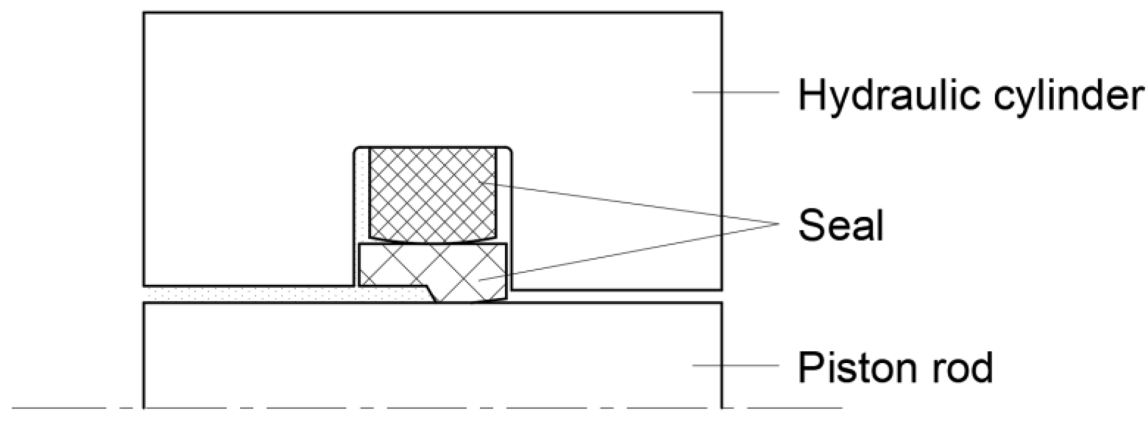
Figure 3 shows the structure of the proposed reciprocating sealing system, which is mainly composed of a hydraulic cylinder, a piston rod, and a sealing ring. When the piston rod and hydraulic cylinder are relatively stationary, the oil in the hydraulic cylinder can be enclosed in the cylinder by a sealing ring. When the piston rod reciprocates relative to the hydraulic cylinder, the oil in the oil cylinder forms a thin oil film in the sealing interface with the movement of the piston rod and is removed from the cylinder by the piston rod, causing leakage.
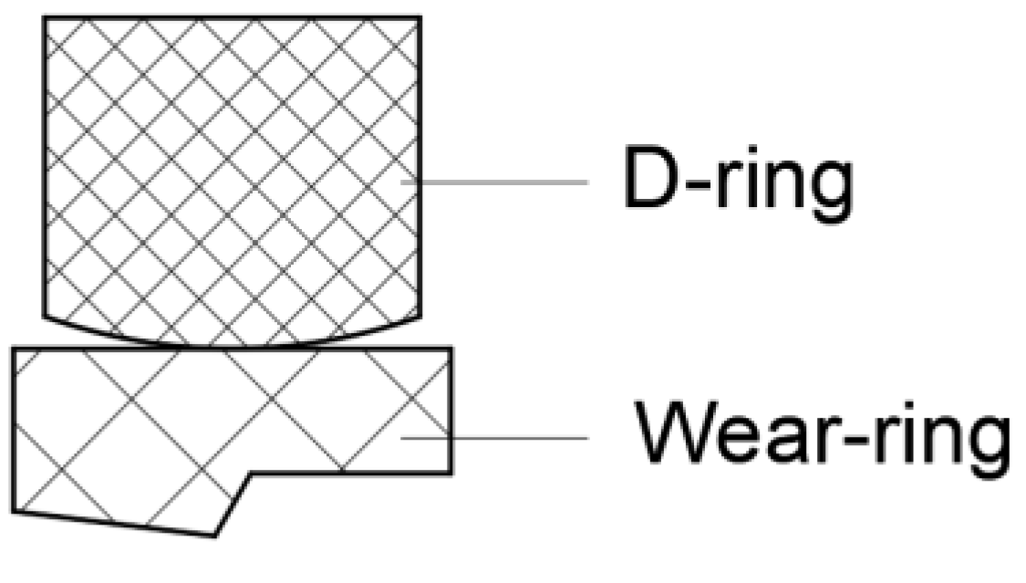
As a commonly used combination seal ring (as shown in Figure 4), a step seal has a compact structure, good sealing performance, and long service life. It is often used in various mechanical structures. The experiments in this study are conducted on the step seal, where the material of the D-ring is nitrile rubber and that of the step ring is polytetrafluoroethylene (PTFE).

2.2. Fluid Mechanics Analysis

According to the aforementioned simplifications and assumptions when using the established model, the IHL method may be used to obtain the oil film thickness distribution in the seal contact area. A simple one-dimensional Reynolds equation (Equation (1)) is used to explain the lubrication characteristics of the seal contact area.
x h 3 η p x = 6 U h x
In the formula, p is the oil film pressure in the seal contact zone, Pa·s; h is the thickness of the oil film in the sealed contact area, m; U is the reciprocating speed of the piston rod, m/s; and η is the viscosity of the lubricating oil. Generally, because the thickness of the oil film in the seal contact area is less than 1 μm, its influence on the radial deformation of the seal ring is negligible relative to the amount of interference (100 μm in the order of magnitude) during interference installation. According to this assumption, the contact pressure distribution of the sealing lip obtained by the finite element simulation analysis is equal to the oil film pressure distribution generated by the fluid. Therefore, according to IHL, the oil film thickness, h , can be obtained inversely using Equation (1).
The outstroke is defined as when the piston rod moves out of the hydraulic cylinder, and the instroke is defined as when the piston rod moves into the hydraulic cylinder. During outstroke, after integrating both sides of Equation (1), it may be rewritten as:
h 3 d p d x 6 η u h h o = 0
In the formula, h o is the film thickness at the point of maximum pressure during outstroke, m.
Assuming that d p d x is known, the oil film thickness h x can be obtained, and differentiating both sides of Equation (2) gives:
h 3 d 2 p d x 2 + d h d x 3 h 2 d p d x 6 η u = 0
Due to the difference between instroke and outstroke, the thickness of the oil film is also different at different strokes. The thicknesses of the oil film during instroke and outstroke are as follows:
h i = 1 2 h i = 1 3 h A = 2 9 × η u i ω A
h o = 1 2 h o = 1 3 h E = 2 9 × η u o ω E
In the formula, ω A = d p d x A , ω E = d p d x E , and A and E are the maximum pressure gradient points during instroke and outstroke, respectively; h i and h o are oil film thickness during instroke and outstroke, m; and h i is film thickness at maximum oil film pressure during instroke, m.
Therefore, the net leakage of a reciprocating piston rod stroke is:
Q = π d L h o h i = π d L 2 η 9 u o ω A u i ω E

2.3. Contact Mechanics Analysis

According to the theory of mixed lubrication, when the oil film thickness of the seal contact area is less than or equal to 3 multiplied by the root mean square roughness ( h 3 σ ), the two contact surfaces must have peak surface roughness contact, and rough peak contact stress is generated, which affects the normal deformation of the sealing lip and generates friction. This study used the Greenwood–Williamson (G–W) contact model to calculate the contact stress between the seal ring and the piston rod.
The G–W model simplifies the actual surface roughness peaks using a rough surface and an absolutely smooth surface to replace the actual rough peak contact problem of the two surfaces. We assumed that the roughness peaks and surface roughness peaks comprise a regular hemisphere with a radius, R. Because the wave trough does not touch the plane, it is filled with a straight line. Figure 5 shows the schematic diagram of the contact between the rough peaks of the contour ball and the smooth surface; h represents the film thickness, y S represents the distance between the average centerline of the actual surface and the average centerline of the wave crest, z represents the distance from the top of the rough peak to the average midline of the crest, d represents the distance between the smooth surface and the average center line of the crest, and ω S represents the amount of deformation of the rough peak. Therefore, the contact area, A e , and the contact pressure, p c , between a smooth and rough surface can be expressed as:
A e = π η A n R S d Γ z z d d z
p c = F A n = 4 3 ρ R S 1 / 2 E d Γ z z d 3 / 2 d z
where Γ z is the probability density function of the crest, F is the total contact load, ρ is the rough peak density on the nominal contact area, A n , and E is the equivalent elastic modulus of the two surfaces. In this article, assuming that the material property of the piston rod is a rigid body, then:
Γ z = 1 2 π σ e z 2 2 σ S 2
E = E 1 υ 2
where σ S is the standard deviation of the wave crest and E and υ are the elastic modulus and Poisson’s ratio of the stepped ring material, respectively.
Equations (7) and (8) show that the contact area, A e , and contact stress, p c , are functions of the distance, d , between the smooth surface and the average center line of the wave crest, as shown in Figure 4:
d = h y S
Hence, we can acquire:
A e = π η A n R S h y s 1 2 π σ S e z 2 2 σ S 2 z h + y s d z
p c = 4 3 ρ R S 1 / 2 E 1 υ 2 h y s 1 2 π σ S e z 2 2 σ S 2 z h + y S 3 / 2 d z
Owing to the rough peak contact on the contact surface, the frictional shear stress between the sealing ring lip and piston rod is:
τ f = f p c
where f is the empirical friction coefficient and p c is the rough peak contact stress.

2.4. Solid Mechanics Analysis

Considering the aviation seal as an example, finite element analysis of the reciprocating seal structure was performed using ABAQUS software, and a finite element model was established, as shown in Figure 6. The coefficients of friction between the D-ring and the sealing groove, between the stepped ring and the piston rod, between the stepped ring and the sealing groove, and between the D-ring and the stepped ring were set to be 0.5, 0.3, 0.3, and 0.8, respectively. In finite element analysis, the interference installation process of the step seal can be simulated by changing the displacements of the step seal, the piston rod, and the sealing groove. Boundary conditions were defined, and an analysis step was added for the interference fit process. First, the D-ring was pre-compressed, and the D-ring was moved to the right by 0.3 mm in the X direction. Second, the pre-compression of the D-ring was cancelled, the sealing groove was positioned, and the sealing groove was moved to the left in the X direction by 0.3 mm. Finally, the piston rod was positioned, and the piston rod was moved horizontally to the right by 0.375 mm in the X direction, completing the interference installation.
Excessive stress and strain values could cause a failure of the sealing ring. Therefore, the extent to which the sealing ring is prone to failure may be determined through calculating and analyzing the maximum stress and strain of the sealing ring during the reciprocating sealing process and its location. When the contact pressure of the lip reaches a certain value, it can ensure that the seal does not leak. A larger lip contact width enhances the reciprocating sealing performance of the step seal.
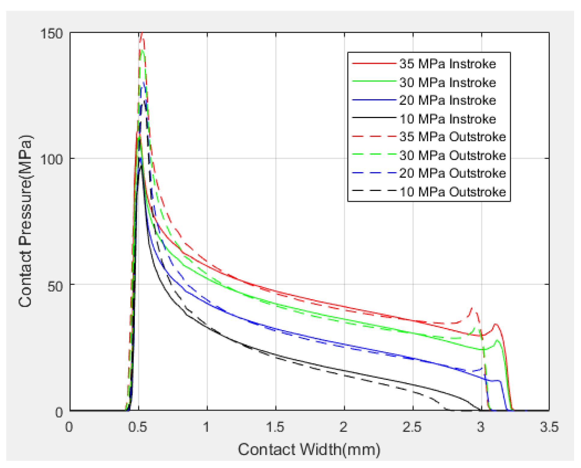
After calculating the contact pressure distribution of the lip, the method of inversely solving the Reynolds equation can be used to obtain the oil film thickness distribution in the contact area of the lip. Furthermore, the friction force between the step seal and the piston rod, and the leakage of the reciprocating sealing system, can be calculated. The contact pressure distribution of the stepped ring lip of the step seal under different oil pressures is calculated, providing data for the subsequent numerical model calculations. The calculated seal lip contact pressure is shown in Figure 7.

2.5. Thermal Analysis

The temperature distribution of the lubricating oil film is a key factor affecting the lubrication performance of the sealing system. Temperature variations change the viscosity of the lubricating oil, affecting the pressure distribution and carrying capacity of the oil film. The change of temperature changes the oil viscosity, which affect the oil film pressure, oil film thickness, system friction, and system leakage of the reciprocating seal. The changes in these parameters have a significant impact on the sealing performance and life of the reciprocating sealing system. The temperature change of the reciprocating seal gap affects the oil film pressure distribution and bearing capacity of the oil film of the reciprocating seal gap [39]. Oil drop viscosity drops rapidly with increasing temperature, and the secondary tangent, 1 η d η d T , of the two changes has a polynomial form (where η is the viscosity of the oil and T is the temperature).
The effect of environmental temperature on oil viscosity is considerably more important than that of microscopic conditions. Therefore, in this study, the influence of ambient temperature on oil viscosity is considered, and oil viscosity is calculated using the Reynolds viscosity-temperature equation (Equation (15)), which provides parameters for subsequent numerical calculations.
η = η 0 e β T T 0
where η 0 and η are the oil viscosity at temperatures T 0 and T , respectively, and β is the viscosity–temperature coefficient, which can be approximately taken as 0.03/°C.

2.6. Calculation Process

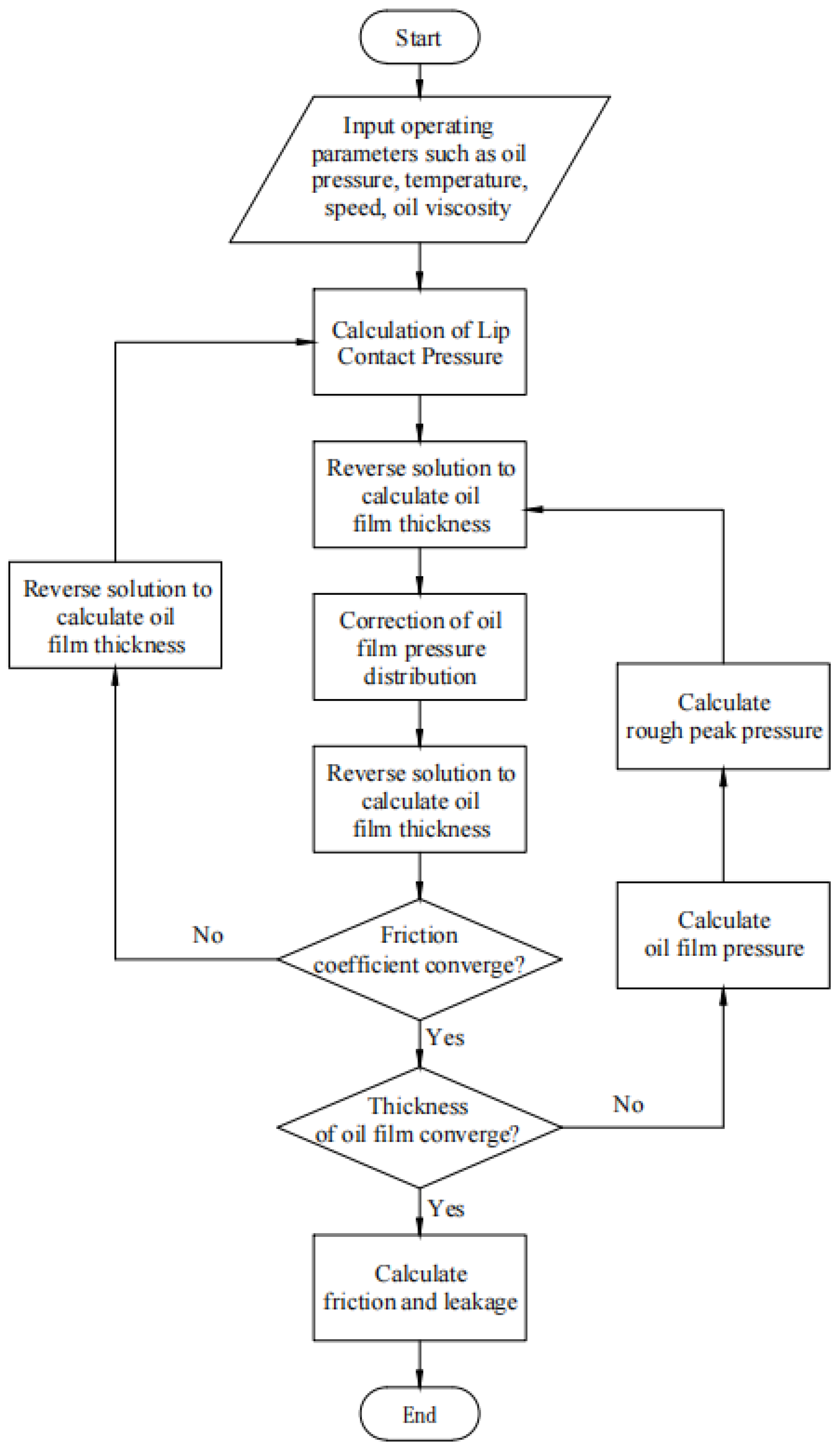
Combining fluid mechanics, contact mechanics, solid mechanics, and thermal analyses, the entire calculation process for the proposed reciprocating seal mixed lubrication model can be obtained, as shown in Figure 8.

3. Reciprocating Sealing Bench Test

3.1. Reciprocating Seal Mixed Lubrication Model

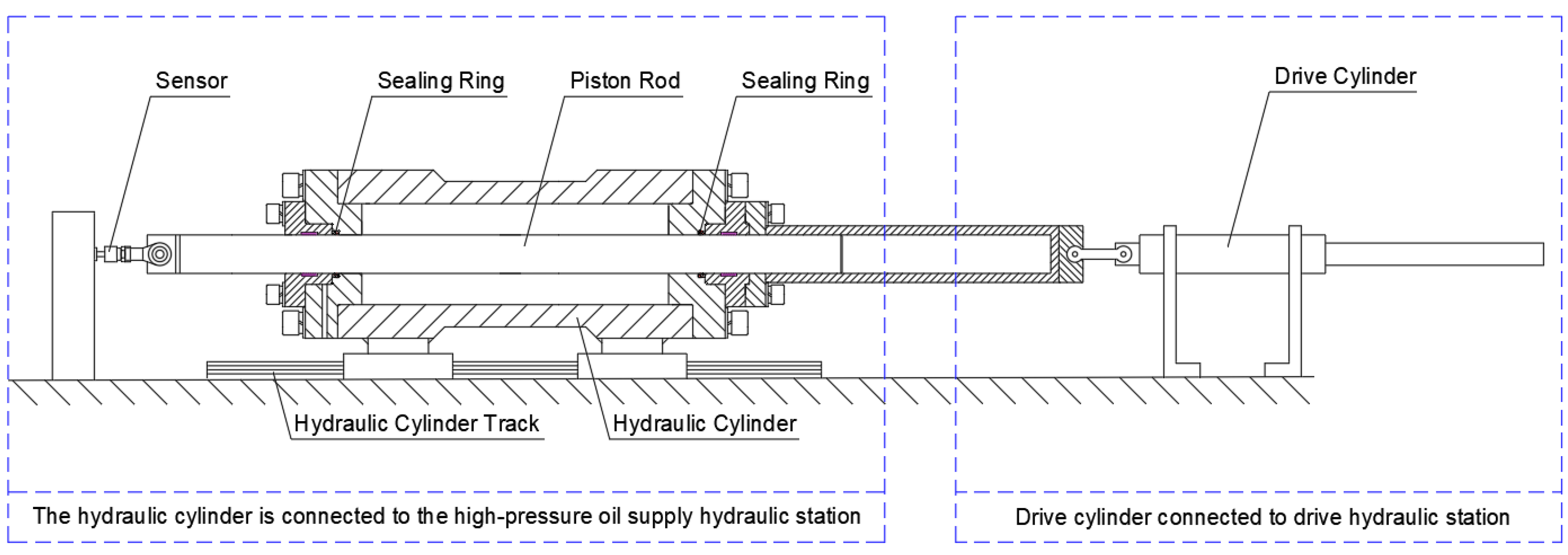
The structure of the test bench is shown in Figure 9, and consists of components such as hydraulic cylinders, piston rods, tested seals, and tension and compression sensors. To eliminate interfering factors such as inertial force and gravity, the test bench is placed horizontally. The piston rod is fixed during the experiment, and the hydraulic station allows the hydraulic cylinder to reciprocate on a fixed track [40]. The hydraulic cylinder receives oil from the hydraulic station to reach the experimental oil pressure, and the pressure is measured with the tension and pressure sensor installed at one end of the piston.
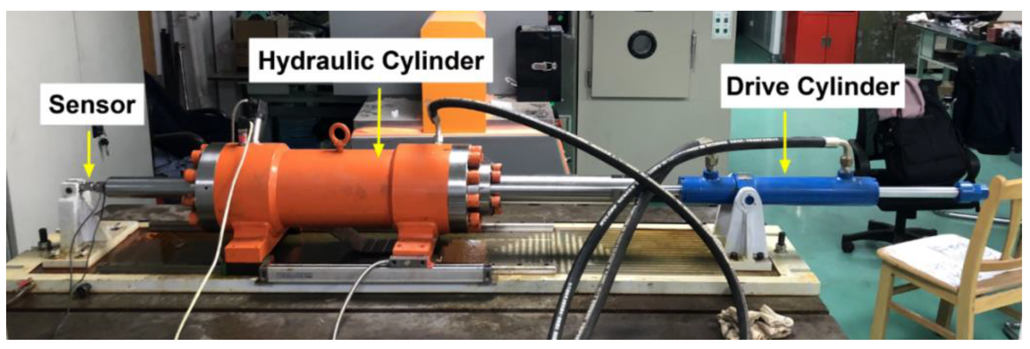
Seals 1 and 2 in the reciprocating sealing test bench are both steady seals and are installed symmetrically. When the hydraulic cylinder moves in the horizontal direction, the friction force between the two seals and the piston rod can be measured by the tension and pressure sensor at one end of the piston rod. A picture of the experimental platform is shown in Figure 10.
A heavy-duty shaft stepped ring GMSS, purchased from the Sealing Research Institute of Guangzhou Mechanical Science Research Institute Co., Ltd., Guangzhou, China was used for the reciprocating sealing bench experiment. The purchased sealing rings were all step seals, and their structure is shown in Figure 4. The material of the Sterling D-ring was nitrile rubber, and the material of the step ring was PTFE filled with glass fiber and MoS2 (the filling ratio was approximately 15%). According to practical experience, commonly used actuator piston rod materials were selected for these experiments. The base material of the piston rod used in this experiment was stainless steel, and the coating material on the outside of the piston rod was chromium (Cr). No. 15 aviation oil was used as the lubricant. The range of the tension and compression sensors was 0~200 kg, the sensitivity was 1.0~2.0 mv/V, the nonlinearity was ±0.1% F.S, the repeatability error was ±0.1% F.S, and the operating temperature range was −20~70 °C.

3.2. Experimental Operation

The experimental procedure was as follows:
  • Turn on the main power supply of the test bench and turn on the high-pressure supply and pressure hydraulic and drive hydraulic stations.
  • Set the direction of the hydraulic cylinder approaching the pressure sensor as the instroke and the direction of the hydraulic cylinder moving away from the pressure sensor as the outstroke.
  • Set the oil pressure. Obtain the experimental hydraulic cylinder oil pressure by adjusting the pressure from the hydraulic station.
  • Set the reciprocating speed. Obtain the experimental reciprocating speed of the driving hydraulic cylinder by adjusting the drive hydraulic station.
  • Set the oil temperature. Set and control the oil temperature by adjusting the temperature of the oil supply hydraulic station. Set the oil temperature to 20, 40, and 100 °C.
  • Set the number of reciprocations of the experiment and turn on the automatic mode to conduct the experiment and record the experimental data.
Considering the step seal for aviation actuators as an example, the material of the D-ring was nitrile rubber, and the step ring material was PTFE with MoS2 and glass fiber. The working environment was at a high pressure of 35 MPa and a speed of 500 mm/s. In this experiment, the oil pressure was set to 10, 20, 30, and 35 MPa, the reciprocating speed was set to 100, 200, 300, 400, and 500 mm/s, and the number of reciprocating times in each experiment was set to 300. According to the different experimental oil pressures and reciprocating speeds, twenty sets of experiments were conducted.

4. Results

4.1. Calculation Results of Numerical Model

MATLAB software was used to implement the mixed lubrication model of the reciprocating seal. The main initial parameters input by the program are shown in Table 1.
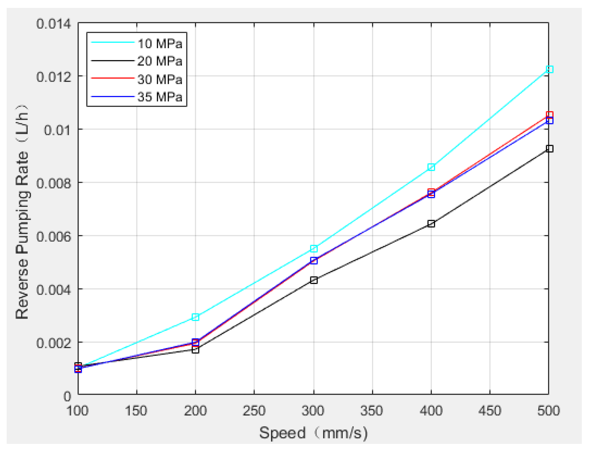
The leakage and friction of the instroke and outstroke under different oil pressures and different reciprocating speeds were obtained using MATLAB; the reverse pumping rate is defined as the flow difference between the instroke and the outstroke, and opposite to the leakage. Equation (16) is the calculation formula used to obtain the reverse pumping rate. When the reverse pumping rate is greater than zero, the reciprocating seal structure has an excess pumping capacity and good sealing performance. Conversely, when the reverse pumping rate is less than zero, the sealing performance is poor and there is liquid leakage.
Δ Q = Q i n Q o u t
In the formula, Δ Q is the reverse pumping rate, L/h; Q i n and Q o u t are the oil flow through the sealing interface during the instroke and outstroke of the reciprocating seal system, L/h.
The reverse pumping rate and friction were calculated according to the material parameters used in the experiment.

4.1.1. Reverse Pumping Rate

The oil flow through the sealing interface during instroke and outstroke flow can be obtained from the aforementioned calculations. Considering an oil temperature of 20 °C, oil pressures of 10, 20, 30, and 35 MPa, and reciprocating speeds between 100 and 500 mm/s as examples, the instroke and outstroke flows are shown in Figure 11. Figure 12 shows the reverse pumping rate.
Using an oil pressure of 35 MPa and a reciprocating speed of 500 mm/s as an example, and setting the oil temperature to −60, −40, 20 (calculated above), 40, and 100 °C, we calculated the reverse pumping rate and compared and analyzed the results.
Table 2 lists the instroke and outstroke flow and the reverse pump rate at different temperatures.

4.1.2. Friction

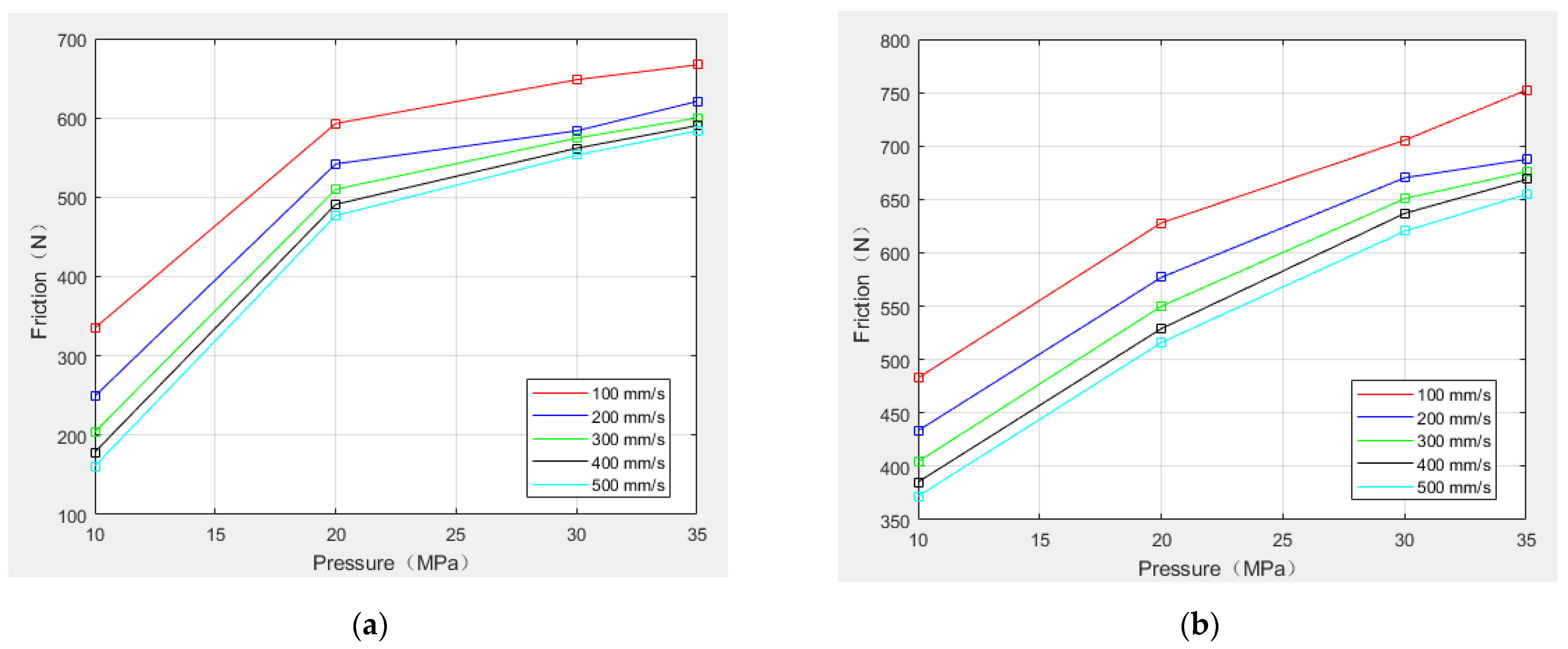
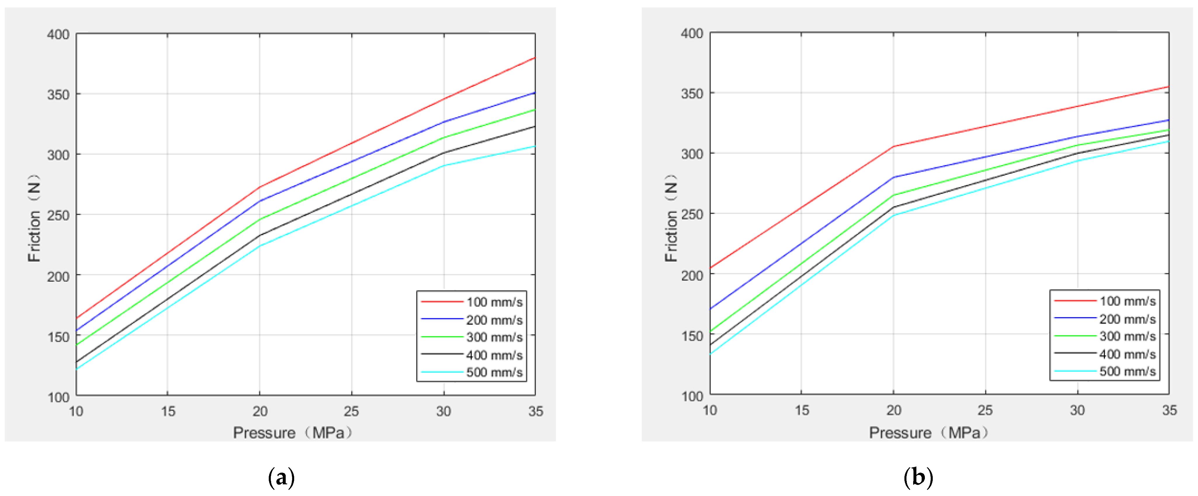
The results for friction with varying pressures shown in Figure 13 indicate that the frictional force of the reciprocating seal system is proportional to the oil pressure and inversely proportional to the speed.
Figure 14 shows the calculated friction law for the instroke and outstroke of the proposed reciprocating seal system at different temperatures.

4.2. Experimental Results

Figure 15 shows the experimentally measured and theoretically calculated data for average friction force with changes in oil pressure and speed. The oil pressure was set as 10, 20, 30, and 35 MPa, and the reciprocating speed as 100, 200, 300, 400, and 500 mm/s. Figure 15a shows the experimentally measured friction force at different oil pressures and speeds, and Figure 15b shows the theoretical calculated friction force at different oil pressures and speeds.
The temperature of the oil was set and controlled by adjusting and setting the high-pressure oil supply hydraulic station. As the experimental device designed and built in this study can only be used to heat the oil (the oil temperature cannot be lower than room temperature), the oil temperature was only set to 40 and 100 °C, the oil pressure was set to 35 MPa, and the reciprocating speed was set to 500 mm/s when performing the reciprocating seal bench tests and recording the experimental data.

5. Discussions

5.1. Reverse Pumping Rate

Figure 11 shows that, at an equal reciprocating speed, the instroke and outstroke flow rates are inversely proportional to the oil pressure. Under an equal oil pressure, the instroke and outstroke flows are proportional to the speed. This is because oil flow rate is proportional to oil film thickness, and the film thickness of the seal contact area is inversely proportional to oil pressure and proportional to speed.
Figure 12 shows that the reverse pumping rate is always greater than zero under different oil pressures and speeds. This implies that the sealing structure of the reciprocating seal has a good sealing performance at 20 °C and does not easily leak.
The calculation results show that the flow rate of the instroke flow is always greater than that of the outstroke flow; therefore, the reverse pumping rate is always greater than zero. As the temperature increases, the viscosity of the oil decreases, and the thickness of the oil film decreases. The trends of instroke and outstroke flow with temperature are the same as that of oil viscosity with temperature. The reverse pumping rate decreases as the temperature rises, but it is always greater than zero. These results indicate that the sealing system presents a good sealing performance at −60–100 °C.

5.2. Friction

Under the same oil pressure and reciprocating speed, the friction of outstroke flow is greater than that of instroke flow. In Figure 13, the calculation shows that when the oil pressure is high (30 and 35 MPa), the friction force of the outstroke flow is approximately 11% greater than that of the instroke flow. When the oil pressure is minimized and the reciprocating speed is maximized, the friction is minimized at 161.1 and 372.1 N for instroke and outstroke flows, respectively. When the oil pressure is maximized and the reciprocating speed minimized, the friction is maximized at 666.9 and 752.3 N for the instroke and outstroke flows, respectively.
Figure 14 shows that the friction force during outstroke flow is always greater than that of the instroke flow. At temperatures between −60 and −40 °C, the friction force decreases rapidly as the oil temperature rises, after which, the friction force decreases slowly. The minimum friction force is calculated at 20 °C, after which the friction force increases slowly with increasing oil temperature. As system friction is the sum of the rough peak contact friction and the oil viscous friction force, the rough peak contact friction and oil viscous friction are to be analyzed.
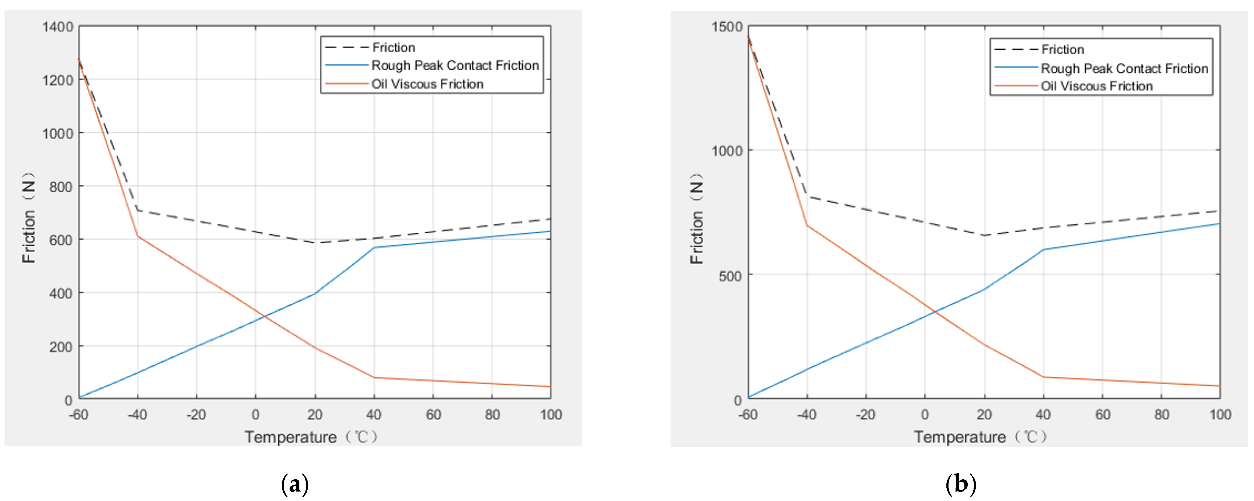
Figure 16 shows that the rough peak contact friction is directly proportional to the oil temperature, and the oil viscous friction is inversely proportional to the oil temperature. This is because the increase in oil temperature reduces the viscosity of the oil and the thickness of the oil film, which leads to an increase in rough peak contact pressure and a decrease in oil film pressure. When the oil temperature is less than 0 °C, the friction of the system mainly depends on the viscous friction of the oil, because at low temperatures, the thickness of the oil film in the seal contact area increases, and the contact area of the surface roughness peak decreases. Hence, the oil viscous friction is greater than the rough peak contact friction. When the oil temperature is greater than 0 °C, the thickness of the oil film decreases, and the contact area of the surface roughness peak increases. The friction of the system mainly depends on the rough peak contact friction. Friction increases with oil temperature, following a similar trend to that of rough peak contact friction, while oil viscous friction is more sensitive to temperature. Therefore, as temperature rises, the decrease in oil viscous friction has a greater influence on the seal system. According to the above analysis, the proposed sealing system can ensure good sealing performance for oil temperatures between −40 °C and 100 °C.
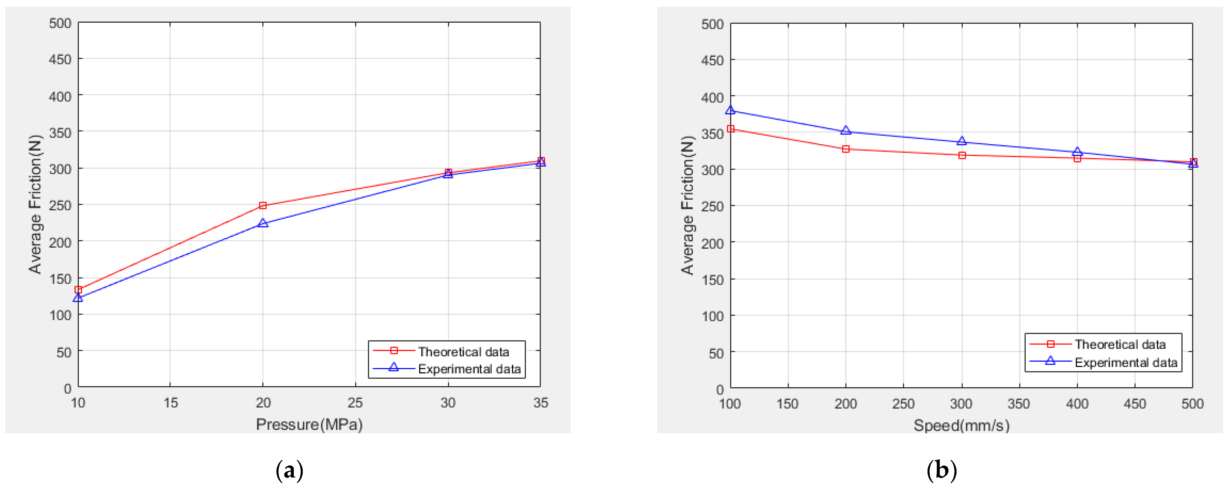
Figure 15 shows that the average experimental friction force is directly proportional to the oil pressure and inversely proportional to the reciprocating speed. The experimental data and theoretical calculations are consistent, with only a slight error. This error is caused by the processing of the experimental table and part installation. Moreover, in terms of the theory, assumptions and simplifications were made in both the establishment of the reciprocating seal mixed lubrication model and derivation of the Reynolds equation in the fluid theory analysis, such as ignoring transient effects, inertial force, and the viscoelasticity of the seal ring materials.
Figure 17 shows the variation in relative error between the experimental measurements and theoretical calculation values with oil pressure and reciprocating speed. When the oil pressure is 10 MPa and the reciprocating speed is 100 mm/s, the relative error is maximized at 19.91%. As the oil pressure and reciprocating speed increase, the relative error falls below 10%.
Figure 18 shows a comparison of the experimental data and the theoretical calculation in terms of the average friction force when the experimental oil temperature is 20 °C, the oil pressure is 35 MPa, and the reciprocating speed is 500 mm/s. The theoretical calculation results are consistent with the experimental friction measurements, and the relative errors are small. The correctness of the proposed theoretical calculation method is therefore verified by the reciprocating seal bench experiment.
Table 3 lists the average friction obtained from experimental measurements and theoretical calculations at oil temperatures of 20, 40, and 100 °C under the same working conditions.
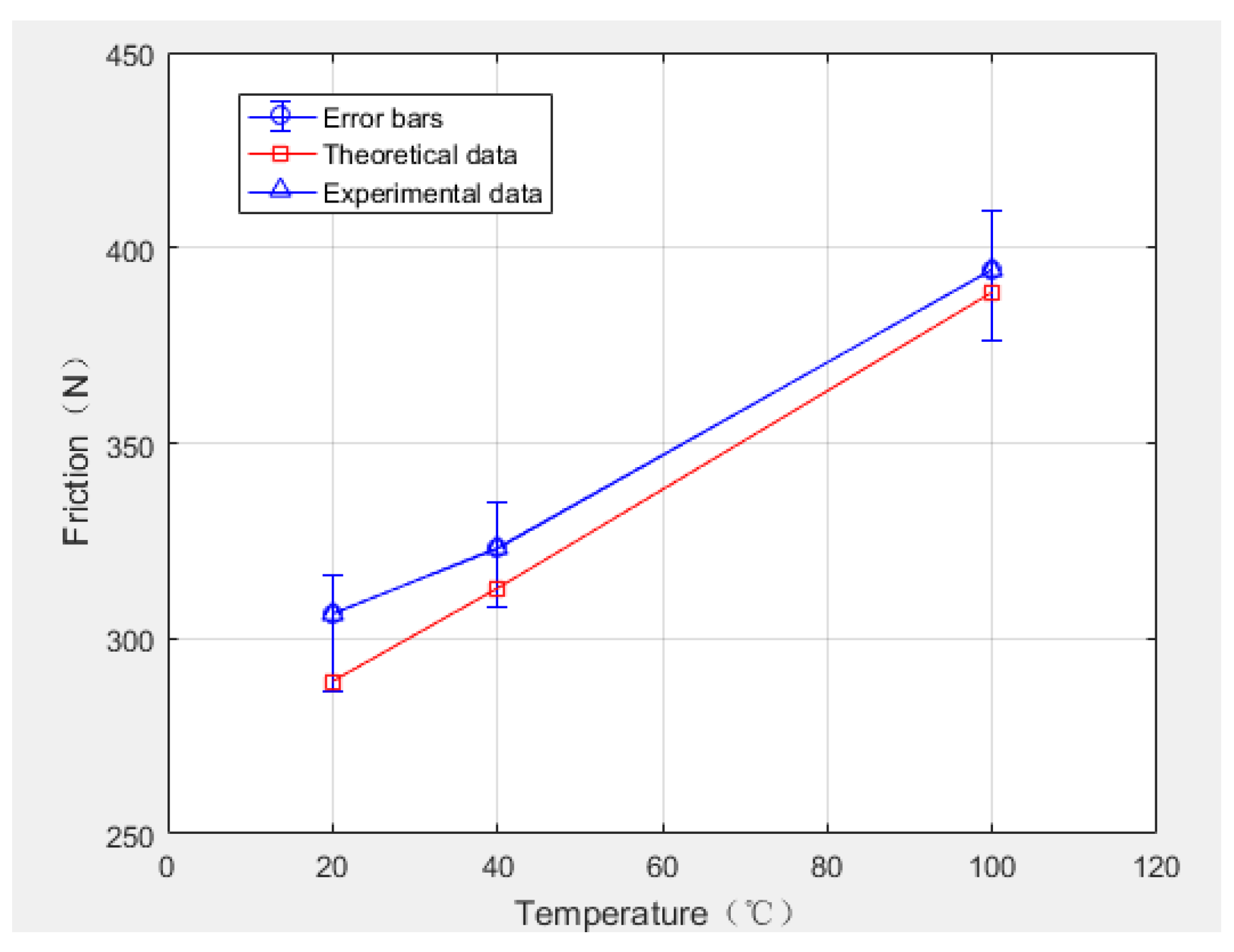
Figure 19 shows a comparison chart of experimental measurements and theoretical calculations. When the oil temperature is 20–100 °C, the theoretical calculation results are consistent with the experimental friction measurement results, and the relative error is small. The relative errors corresponding to 20 °C, 40 °C, and 100 °C are 5.64%, 3.23%, and 1.51%, respectively, which also verifies the correctness of the theoretical calculation method.

6. Conclusions

(1)
Based on the sealing mechanism of the reciprocating seal, EHL and IHL methods were used to solve the Reynolds equation, and a reciprocating seal mixed lubrication model was established based on the hydrodynamic analysis of the lubricating oil, contact mechanics analysis of the seal contact area, solid mechanics analysis of the seal lip, and thermal analysis of the oil temperature.
(2)
The reverse pumping rate (leakage) and friction force of reciprocating sealing were calculated at different temperatures. The correctness of the theoretical model was experimentally verified using a reciprocating seal bench, and a relatively complete reciprocating sealing system theory was devised.
(3)
Oil film stress decreases with increasing temperature, the rough peak stress increases with increasing temperature, and the oil film thickness decreases rapidly with increasing temperature owing to the viscosity–temperature effect. The flow rate of the instroke is always greater than the outer stroke, and the reverse pumping rate is always greater than zero, i.e., the leakage is less than zero. When the oil temperature is less than 0 °C, the friction in the system mainly depends on the viscous friction of the oil. However, when the oil temperature is greater than 0 °C, the friction in the system mainly depends on the contact friction of the rough peak, and the increase in the contact friction of the rough peak leads to a greater increase in system friction.
(4)
The hydraulic station used in the experiment is only able to heat the oil; therefore, the parameters for oil temperatures between −60 and 0 °C were not tested and verified experimentally in this study. However, low temperature has a significant influence on sealing performance, and the processing optimization and experimental testing of the experimental equipment will be the subject of future work. In addition, the reliability testing, predictive maintenance, and intelligent sealing of reciprocating seals are future development trends. It is crucial to address these factors to reduce the occurrence of catastrophic accidents. At present, there are few studies in these areas, and these are in the preliminary stages; therefore, further research into these factors is required.

Author Contributions

Conceptualization, M.Z.; methodology, M.Z.; software, M.Z.; validation, M.Z.; formal analysis, M.Z.; investigation, M.Z.; resources, M.Z.; data curation, M.Z.; writing—original draft preparation, M.Z.; writing—review and editing, M.Z.; visualization, M.Z.; supervision, Y.F.; project administration, Y.F.; funding acquisition, Y.F. All authors have read and agreed to the published version of the manuscript.

Funding

This research was funded by National Program on Key Basic Research Project; the grant number is 2014CB046404.

Institutional Review Board Statement

Not applicable.

Informed Consent Statement

Not applicable.

Data Availability Statement

Not applicable.

Conflicts of Interest

The authors declare no conflict of interest.

References

  1. Zhang, M.T.; Suo, S.F.; Guo, F.; Jia, X.; Meng, G. Research of Forward Design Method of Contact Dynamic Seal. Hydraul. Pneum. Seals 2018, 9, 25–27. [Google Scholar]
  2. Zhang, M.T.; Li, D.C.; Suo, S.F.; Shi, J.W. Piston Rod Coating Material Study of Reciprocating Sealing Experiment Based on Sterling Seal. Appl. Sci. 2021, 11, 1370. [Google Scholar] [CrossRef]
  3. Tan, G.; Fan, Q.; Tan, F.; Wang, D. Advances in Tribology on Elastomer Sealing and Its Future Trends for the Huge Machinery. Tribology 2016, 36, 559–666. [Google Scholar]
  4. Nikas, G.K. Eighty Years of Research on Hydraulic Reciprocating Seals: Review of Tribological Studies and Related Topics Since the 1930s. Proc. Inst. Mech. Eng. Part J J. Eng. Tribol. 2010, 224, 1–23. [Google Scholar] [CrossRef]
  5. Du, X.Q.; Chen, G.; Yab, X.L.; Zhao, Y.L. Optimization Design of Step Seal-ring Based on ISIGHT Platform. Chin. Hydraul. Pneum. 2017, 14–19. [Google Scholar] [CrossRef]
  6. Wu, C.; Suo, S.; Zhang, K.; Dilixiati, A. Aircraft Actuator VL Seal Finite Element Analysis Based on ABAQUS. Chin. Hydraul. Pneum. 2016, 1, 60–65. [Google Scholar]
  7. Shen, M.; Song, M.L.; Zhang, H. Simulation Analysis of Sealing Performance of ZHM Pneumatic Combined Sealing Ring for Reciprocating Seal Shaft. Inf. Technol. 2021, 50, 104–108. [Google Scholar]
  8. Nau, B.S. An historical review of studies of polymeric seals in reciprocating hydraulic systems. Proc. Inst. Mech. Eng. Part J J. Eng. Tribol. 1999, 213, 215–226. [Google Scholar] [CrossRef]
  9. Gronau, H. Investigations on Gland Packings and Sealing Rings for High Hydraulic Pressures. Ph.D. Thesis, University of Berlin, Berlin, Germany, 1935. [Google Scholar]
  10. White, C.M.; Denny, D.F. The Sealing Mechanism of Flexible Packings; HM Stationery Office: London, UK, 1948. [Google Scholar]
  11. Denny, D.F. The Friction of Rubber Sealing Rings; British Hydromechanics Research Association: Harlow, UK, 1953.
  12. Müller, H. Leakage and friction of flexible packings at reciprocating motion with special consideration of hydrodynamic film formation. In Proceedings of the 2nd International Conference on Fluid Sealing, Granfield, UK, April 1964; pp. 13–28. [Google Scholar]
  13. Ishiwata, H.; Kambayashi, H. A study of oil seal for reciprocating motion. In Proceedings of the 2nd International Conference on Fluid Sealing, Granfield, UK, April 1964. [Google Scholar]
  14. Dowson, D.; Swales, P. An elastohydrodynamic approach to the problem of the reciprocating seal. In Proceedings of the 3rd International Conference on Fluid Sealing, Cambridge, UK, 1967. [Google Scholar]
  15. Theyse, F. The inverse hydrodynamic theory and its application in the design of controlled leakage seals between moving parts. In Proceedings of the 3rd International Conference on Fluid Sealing, Cambridge, UK, 1967; pp. 17–32. [Google Scholar]
  16. Field, G.J.; Nau, B.S. The effects of design parameters on the lubrication of reciprocating rubber seals. In Proceedings of the 7th International Conference on Fluid Sealing, Nottingham, UK, September 1975; pp. 1–13. [Google Scholar]
  17. Nikas, G.K.; Sayles, R.S. Nonlinear elasticity of rectangular elastomeric seals and its effect on elastohydrodynamic numerical analysis. Tribol. Int. 2004, 37, 651–660. [Google Scholar] [CrossRef]
  18. Dowson, D.; Swales, P.D. The development of elastohydrodynamic conditions in a reciprocatingseal. In Proceedings of the 4th International Conference on Fluid Sealing, Cranfield, UK, 1969; pp. 2–10. [Google Scholar]
  19. Field, G.J.; Nau, B.S. An experiment study of reciprocating rubber seals. In Proceedings of the IMechE Symposium on Elastohydrodynamic Lubrication, Leeds, UK, 1972; pp. 29–36. [Google Scholar]
  20. Field, G.J.; Nau, B.S. Film thickness and friction measurements during reciprocation of a rectangular section rubber seal ring. In Proceedings of the 6th International Conference on Fluid Sealing, Munich, Germany, 27 February–2 March 1973; pp. 45–56. [Google Scholar]
  21. Kaneta, M.; Todoroki, H.; Nishikawa, H. Experimental investigation of friction and sealing characteristics of flexible seals for reciprocating motion. In Proceedings of the 5th International Conference on Fluid Sealing, Coventry, UK, 8–12 September 1971; pp. 33–48. [Google Scholar]
  22. Yang, B.; Salant, R.F. Soft EHL Simulations of U-Cup and Step Hydraulic Rod Seals. J. Tribol.-Trans. ASME 2009, 131, 021501. [Google Scholar] [CrossRef]
  23. Yang, B.; Salant, R.F. A numerical model of a reciprocating rod seal with a secondary lip. Tribol.-Trans. 2008, 51, 119–127. [Google Scholar] [CrossRef]
  24. Yang, B.; Salant, R.F. Numerical model of a tandem recipr ocating hydraulic rod seal. J. Tribol.-Trans. ASME 2008, 130, 032201. [Google Scholar] [CrossRef]
  25. Salant, R.F.; Maser, N.; Yang, B. Numerical model of a reciprocating hydraulic rod seal. J. Tribol.-Trans. ASME 2007, 129, 91–97. [Google Scholar] [CrossRef]
  26. Fatu, A.; Hajjam, M. Numerical modelling of hydraulic seals by inverse lubrication theory. Proc. Inst. Mech. Eng. Part J J. Eng. Tribol. 2011, 225, 1159–1173. [Google Scholar] [CrossRef]
  27. Li, J.X. Finite Element Analysis of Piston Seals Property of Hydraulic Cylinders. Master’s Thesis, Northeastern University, Boston, MA, USA, 2005. [Google Scholar]
  28. Kanters, A.F.C.; Verest, J.F.M.; Visscher, M. On reciprocating elastomeric seals: Calculation of film thicknesses using the inverse hydrodynamic lubrication theory. Tribol. Trans. 1990, 33, 301–306. [Google Scholar] [CrossRef]
  29. Nikas, G.K. Elastohydrodynamics and Mechanics of Rectangular Elastomeric Seals for Reciprocating Piston Rods. J. Tribol. 2003, 125, 60–69. [Google Scholar] [CrossRef]
  30. Nikas, G.K.; Sayles, R.S. Study of leakage and friction of flexible seals for steady motion via a numerical approximation method. Tribol. Int. 2006, 39, 921–936. [Google Scholar] [CrossRef]
  31. Nikas, G.K.; Sayles, R.S. Computational model of tandem rectangular elastomeric seals for reciprocating motion. Tribol. Int. 2006, 39, 622–634. [Google Scholar] [CrossRef]
  32. Crudu, M.; Fatu, A.; Cananau, S.; Hajjam, M.; Pascu, A.; Cristescu, C. A numerical and experimental friction analysis of reciprocating hydraulic ‘U’ rod seals. Proc. Inst. Mech. Eng. Part J J. Eng. Tribol. 2012, 226, 785–794. [Google Scholar] [CrossRef]
  33. Bhaumik, S.; Kumar, S.R.; Kumaraswamy, A. Experimental Investigation and FE Modelling of Contact Mechanics Phenomenon in Reciprocating Hydraulic U-Seals for Defence Applications. Appl. Mech. Mater. 2014, 592–594, 1950–1954. [Google Scholar] [CrossRef]
  34. Wang, C.; Xiao, J.; Liu, H.; Liu, J.; Xing, G.C. Finite Element Analysis of Sealing Performance of Glyd-ring Seals. J. Wuhan Inst. Technol. 2014, 36, 12–15. [Google Scholar]
  35. Han, C.; Hu, Y.; Zhang, J.; Xie, J.X. Mechanical Properties Analysis and Structure Improvement of Tooth and Sliding Ring Combined Seals. Lubr. Eng. 2018, 43, 86–92. [Google Scholar]
  36. Yi, P.; Jin, Y.; Peng, Y.; Wan, B. Performance Analysis of Combined Seal Structure in Deep Sea High Pressure Environment. J. Hunan Univ. Sci. Technol. 2018, 33, 34–39. [Google Scholar]
  37. Wang, J.; Liao, Y.; Li, Y.; Lian, Z. Investigations on the dynamic reciprocating sealing performance with partial lubrication model. Lubr. Eng. 2020, 45, 50–55. [Google Scholar]
  38. Qin, Z.; Zhou, P.; Zhang, B.; Li, H.; Zhang, H.; Guo, D. Simulation and experimental study on sealing performance of PEEK rotary seal ring. Tribology 2020, 40, 330–338. [Google Scholar]
  39. Wen, S.; Huang, P.; Tian, Y.; Ma, L. Principles of Tribology, 5th ed.; Tsinghua University Press: Beijing, China, 2018; pp. 49–53. [Google Scholar]
  40. Visscher, M.; Kanters, A. Literature review and discussion on measurements of leakage, lubricantfilm thickness and friction of reciprocating elastomeric seals. Lubr. Eng. 1990, 46, 785–791. [Google Scholar]
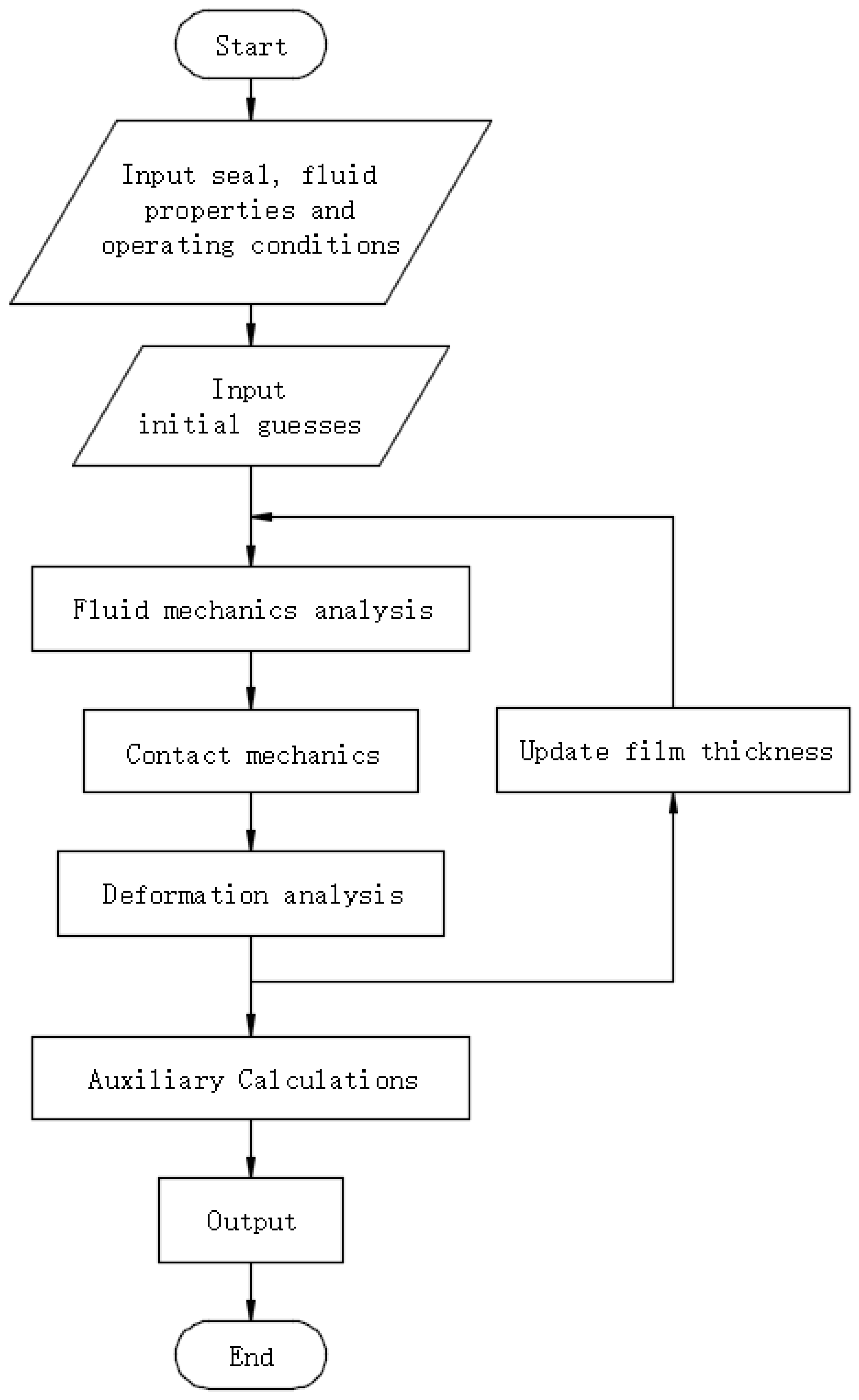
Figure 1. Flow chart of the numerical model established.
Lubricants 10 00153 g001
Figure 2. Schematic of the reciprocating seal contact area.
Lubricants 10 00153 g002
Figure 3. Reciprocating sealing system.
Lubricants 10 00153 g003
Figure 4. Sectional view of step seal.
Lubricants 10 00153 g004
Figure 5. Surface contact between the equivalent rough peak and the smooth surface.
Lubricants 10 00153 g005
Figure 6. Von Mises stress cloud diagram after installation.
Lubricants 10 00153 g006
Figure 7. Contact pressure distribution of seal lip under different pressures.
Lubricants 10 00153 g007
Figure 8. Calculation flowchart of reciprocating seal mixed lubrication model.
Lubricants 10 00153 g008
Figure 9. Schematic of experimental bench structure.
Lubricants 10 00153 g009
Figure 10. Physical picture of the hydraulic cylinder of the reciprocating sealing experiment bench.
Lubricants 10 00153 g010
Figure 11. Flow rate variation of instroke and outstroke with oil pressure.
Lubricants 10 00153 g011
Figure 12. Reverse pumping rate variation.
Lubricants 10 00153 g012
Figure 13. Friction of instroke and outstroke with oil pressure and speed: (a) Instroke; (b) Outstroke.
Lubricants 10 00153 g013
Figure 14. Friction of instroke and outstroke with temperature.
Lubricants 10 00153 g014
Figure 15. Average friction variation with oil pressure and speed at 20 °C: (a) Experimental data; (b) Theoretical data.
Lubricants 10 00153 g015
Figure 16. Schematic of three types of friction of instroke and outstroke with temperatures: (a) Instroke; (b) Outstroke.
Lubricants 10 00153 g016
Figure 17. Relative error between experimental measurement and theoretical calculation: (a) Relative error with oil pressure; (b) Relative error with speed.
Lubricants 10 00153 g017
Figure 18. Comparison of experimental and theoretical data of average friction: (a) Variation of average friction with oil pressure; (b) Variation of average friction with speed.
Lubricants 10 00153 g018
Figure 19. Variation of average friction force with temperature at different temperatures.
Lubricants 10 00153 g019
Table 1. Program initial parameters.
Parameter NameNumerical Value
Elastic Modulus297 MPa
Poisson’s Ratio0.45
Oil Viscosity (20 °C)9 × 10⁻⁸ MPa·s
Friction Coefficient0.08
Piston Rod Diameter50 mm
Table 2. Oil flow and reverse pumping rate of instroke and outstroke at different temperatures (L/h).
Temperature−60 °C−40 °C20 °C40 °C100 °C
Instroke flow0.062780.031500.011810.0056250.003425
Outstroke flow0.062590.031420.011760.0055790.003382
Reverse pumping rate1.9 × 10−48.0 × 10−55.0 × 10−54.6 × 10−54.3 × 10−5
Table 3. Experimental and theoretical data of average friction force.
Temperature20 °C40 °C100 °C
Theoretical calculation of average friction (N)290.0312.8388.6
Experimental measurement of average friction (N)306.4322.9394.5
Relative errors5.64%3.23%1.51%
Publisher’s Note: MDPI stays neutral with regard to jurisdictional claims in published maps and institutional affiliations.