Abstract
The novel results reported here present qualitative and quantitative regularities of the deformation behavior of a spherical bearing with a different location and inclination angle of the antifriction layer. A number of topical problems encountered during the assessment of the performance bearings are considered in the work. The spherical bearings of the bridge span are investigated. Structures are load-bearing elements of transport systems. They perceive thermal power loads from the bridge span. The temperature problem is not considered in this study. In this paper, a comparative analysis of the bridge spherical bearing operation at different antifriction layer locations was performed. Two bearing geometries are considered: the interlayer is pressed in a spherical segment (classical geometry); the interlayer is pressed into a recess located in the lower steel plate. The six modern antifriction materials considered proved suitable to some extent as contact unit sliding layers for various purposes. Additionally, the influence of the inclination angle of the antifriction layer end face on the structure operation for all sliding layer material variants was analyzed. It has been established that the bearing design with an interlayer in the lower steel plate has a more favorable deformation behavior. Changing of the inclination angle of the antifriction layer end face leads to a decrease in the maximum level of contact parameters and deformation characteristics for all the considered structures.
Keywords:
polymers; composite materials; friction; contact; bridge bearing; sliding; modeling; geometry 1. Introduction
1.1. Research Objectives
The study purposes: performance comparison of spherical bearing of bridges two geometries differing in the antifriction layer location; influence analysis of the antifriction layer materials and the inclination angle end face to work of design.
Research tasks:
1. The work of two variants of the spherical bearing geometry is compared in an axisymmetric formulation.
2. The antifriction layer material effect is evaluated.
3. Analysis of the influence of the inclination angle of the antifriction layer end face on the stress–strain state of structures.
1.2. Problem Context
The first metal bridge structure was built in 1779. This design and its elements have been studied from different angles over the course of all subsequent years. Bridge structures of various types can be found today [1]: adjustable and fixed; spacer, beam or combined; arched and suspended. Structural features of various types of bridges and their elements are described by many authors [2,3]. The tasks of the structure durability, its economically profitable construction, and the increase in its load-bearing capacity are researched [4]. The issues of preventive maintenance of bridges and their elements are also relevant to ensure the safety and serviceability of existing structures [5]. Wear models are often built from regular records of the bridge condition based on visual inspections [4,6]. The bridge state is determined by the main elements: supports, bearings, spans, etc. Calvert et al. proposed to include defects in the main structural elements and the interaction between them in the analysis of the bridge life cycle [7]. The use of information and communication technologies and robots to assess the current state of bridges and their elements is promising [6,8].
Cost analysis for the restoration of deteriorating structures and optimization of their service life and reliability are topical tasks in bridge building [9,10]. Replacing load-bearing structures, such as bridge bearings, is labor-intensive and costly [11,12,13]. Loss of element stability, disconnection of carrier nodes, overload, etc., are the main causes of the critical state or the destruction of bridges [14,15,16]. The operability of structures is associated with a breakdown or bearing capacity loss of elements: expansion joints [17,18], bearing [19,20,21,22], spans [22,23], lifting structures of drawbridges [24], and others. The tasks of rationalization and optimization of the principal load bearing elements are constantly relevant. This is due to the constant growth of the car park and the increase in the load on transport systems [14,25]. Now, manufacturers are striving not for mass production, but for the selection of structural parts for the bridge structure work, e.g., the selection of the sliding layer material in the bearing for the bridge span maximum load. These tasks are resolved not only for construction bridges planned, but also for already built historical bridges [26,27].
Increasing the strength, load-bearing capacity, and maintenance-free service life of transport systems elements are the main areas of research in this industry. The list of current tasks is quite extensive, including the rationalization and optimization of the designs of critical elements and bridges in general [28,29], new technologies for the creation and restoration [29,30,31,32], introduction of new materials with improved physico-mechanical and operational properties [33,34], as well as changing the geometry and configuration of bearing elements [33]. It is also important to analyze the influence of materials on the unit functionality [35,36].
Significant progress can be noted in the field of creating new modern functional materials for various elements of bridge structures. Materials can show increased value in terms of reliability, durability, and wear resistance. They have improved physical-mechanical, frictional, and rheological properties. Factors that hinder the effective use of modern polymeric materials and composites based on them in many industrial areas and as thin antifriction layers in the bearing of bridge spans are noted in [37,38]. Modern materials can significantly increase the working life of the sliding layer bearings of bridges [39,40,41]: nanofilled and unfilled PTFE, ultrahigh molecular weight polyethylenes (UHMWPE), nanomodified polymeric materials and composites of various brands and production. The particular interest here applies to a comparative analysis of the influence of the antifriction layer materials of the bridge bearings on their deformation behavior. The study of geometric design various modifications of the bearings is also relevant.
1.3. Problem Description
The bearings geometry was flat due to the difficulty of producing a spherical structure initially. Many varieties of bearing geometries now exist. Most of them are considered in [19]. Rubber [42,43,44] and spherical [33,45,46,47] bearings are the most common. Spherical bearings are widely used in bridge structures in transportation systems around the world. This effect is due to the fact that the articular type is the best mechanism for mitigating shocks and ensuring smooth movements in nature. The spherical element in contact with the spherical deepening is an articular type construction [46]. There are many manufacturers of spherical bearings: MAGEBA (Bülach, Switzerland), MAURER (Munich, Germany), FIP MEC (Selvazzano Dentro, Italy), AlfaTech LLC (Perm, Russia), KO Lumi-ere Ltd. LLC (Moscow, Russia), Mostotrest (Moscow, Russia), etc. The different manufacturers bearing differ in the elements design the and the sliding layers materials. Constructions with a sliding layer deposited on a spherical segment are quite common, as noted in [19]. Many manufacturers implement structures with a spherical sliding layer pressed into the bottom steel plate. The question arose about comparing these configurations and identifying the features of their applicability. The interlayer between the contact pairs is used to ensure the structure longevity. The interlayer position, its thickness, the cutout geometric configuration for the interlayer, etc. have a great influence on the bearing deformation process [47].
Tasks related to the use of various polymers and composites in the bridge bearing remain just as relevant. PTFE is one of the most common materials used as a sliding layer in bearings. Its use in its pure form is not always effective, as noted in [48]. For example, the authors [49] noted a decrease in the wear rate of the material after exposure to irradiation on PTFE composites due to increased interfacial interactions of macromolecules. A large set of modern polymeric materials and composites based on them exists and they can be used as antifriction coatings and interlayers in friction units [50,51,52]. New polymeric and composite materials [50,51] can have improved physico-mechanical, frictional, thermomechanical, and rheological properties. UHMWPE and composite materials based on them [20,50,53], antifriction materials based on PTFE [20,50,54], and modified PTFE [52,53,54,55] are antifriction materials.
This work is aimed at comparing the deformation behavior of bridge bearings of different geometry. Spherical bearings are considered. The study also includes an analysis of the performance of interlayers from various modern materials in the bearings.
2. Materials and Methods
2.1. Model
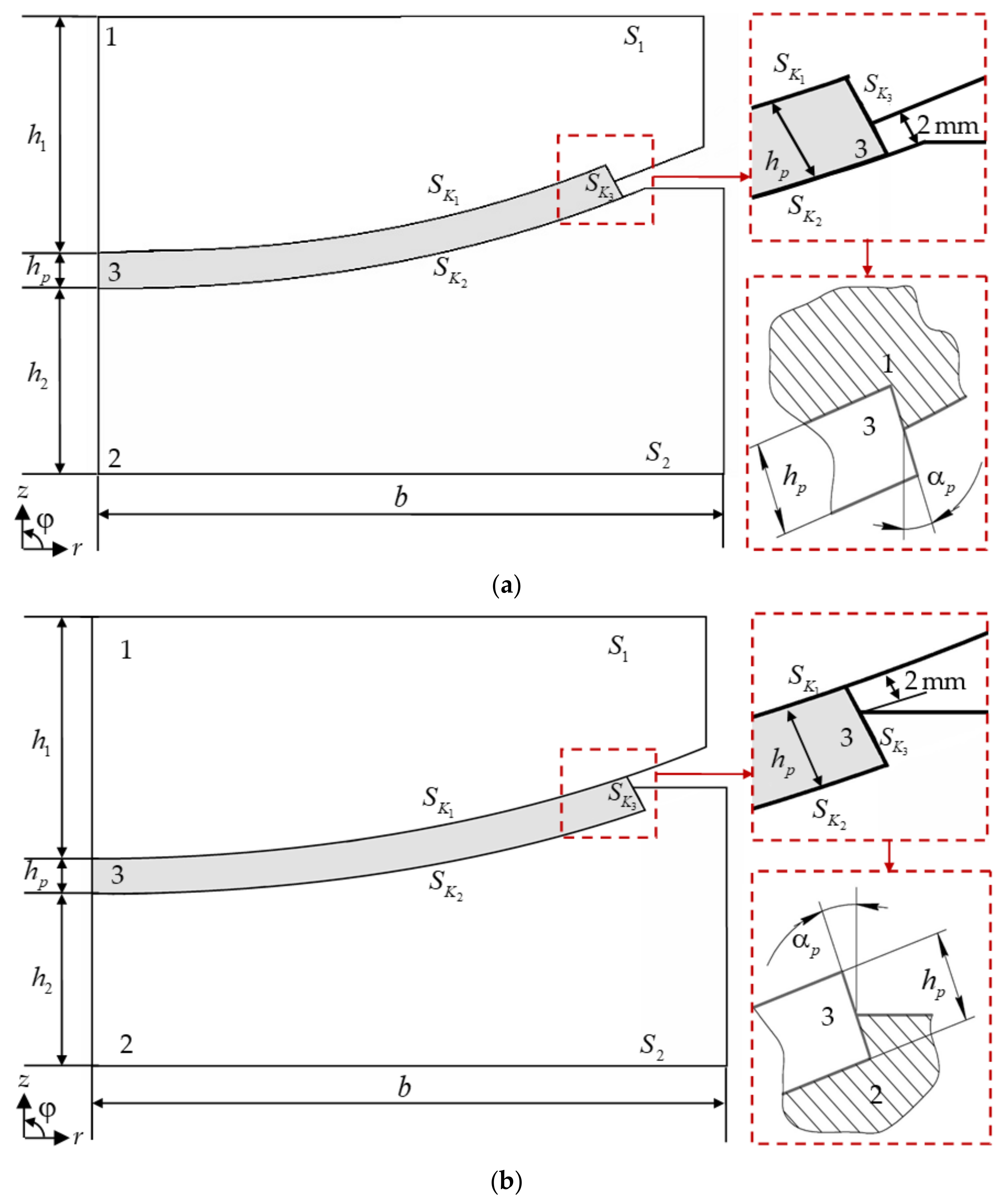
Two variants for the bearing geometry are considered (Figure 1). Model A: an interlayer (3) fills a recess in the upper steel plate (1). Model B: an interlayer (3) fills a recess in the lower steel plate (2). The main overall dimensions of the structure and the load-bearing capacity do not depend on its configuration. Structure height is mm, width is mm, and standard vertical load is 1000 kN. The interlayer thickness is constant mm. The antifriction layer end face (3) is partially in contact with the steel elements. The initial contact surface is 50% of the interlayer thickness (2 mm). Standard inclination angle of the antifriction layer end face is °. The polymer layer is pressed into steel structural elements. Overall dimensions correspond to the minimum standard size of bearings manufactured by AlfaTech LLC.
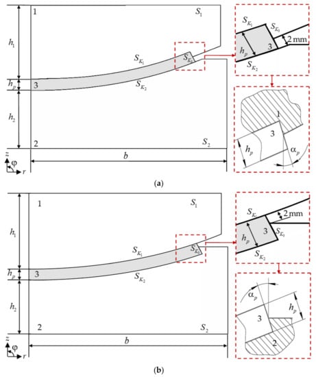
Figure 1.
Calculation scheme of the spherical bearing: (a) is model A; (b) is model B.
The paper considered the contact between the steel bearing elements with an antifriction layer at a constant friction coefficient of 0.04 (according to the data of the bearings manufacturer AlfaTech LLC).
Earlier, the deformation behavior study was carried out with two variants of the bearing geometry [56]. The study was conducted on an example of the layer made from modified PTFE. The contact divergence in model A is observed at the standard angle of the end face. The zone of complete “no contact” on the mating surface, on which the spherical segment is possible rotation, is observed near the antifriction layer edge (model A—). In the bearing of model B, the effect of “no contact” is not observed.
In [57], the authors studied the influence of the inclination angle of the antifriction layer end face (modified PTFE) on the deformation of structures of different geometries. End face angles from 0° to 45° have been investigated. The paper has established that a favorable distribution of the contact zone parameters and the deformation characteristics of the sliding layer is obtained at the inclination angles of the end face of 25 and 40° for model A and 0° for model B.
The analysis of the influence layer material properties on the structure performance of different geometries is of interest. Studies include standard and “rational” .
2.2. Materials
A series of experiments (Figure 2) to determine the antifriction polymer and composite mechanical properties for suitability as a bearing layer was previously carried out on the basis of the IMSS Ural Branch of the Russian Academy of Sciences (Perm, Russia). The research included more than 30 materials. Antifriction materials based on PTFE, ultrahigh molecular weight polyethylenes, and composites based on them with different fillers are researched. Research is aimed at the selection of new antifriction materials with improved performance properties. Optimization of the design performance of the bearing manufactured by AlfaTech LLC is the goal. The experiments are aimed at determining the physico-mechanical and operational characteristics of antifriction polymer and composite materials.
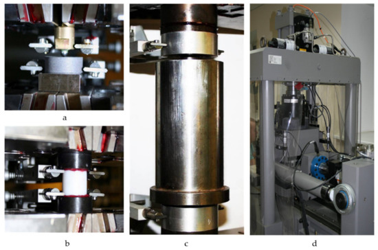
Figure 2.
Experimental studies: (a) is Brinell hardness; (b) is free compression; (c) is cramped compression; (d) is friction studies on the MTS 316 test rig with original equipment.
Regarding the study of physico-mechanical properties, the hardness of materials was assessed according to Brinell, with complicated loading of materials samples under free and constrained compression in the range of working deformations and stresses, etc. A number of materials were excluded from further study based on the experiments results. The main reasons for excluding materials from further consideration:
- −
- materials cannot be produced in the required volume;
- −
- materials have a very heterogeneous set of properties;
- −
- significantly nonlinear compressibility of materials under constrained compression has been discovered;
- −
- additional experimental studies with different histories of long-term multistage loading are required, etc.
The 6 materials with improved properties compared to pure PTFE were selected based on the research results. Pure PTFE is still the most common material for the antifriction layer of bearings [45,58,59]. Materials based on UHMWPE and modified PTFE have almost elastic behavior with weakly non-linear hardening. The rigidity of UHMWPE and modified PTFE is significantly (~1.5 times) higher than the other materials’ rigidity at a pressure level of 50 MPa. Two composites based on PTFE are included in the selected set of materials. Materials are included in the study for comparison. Composites produced by AlfaTech LLC are considered. Materials under study (Table 1): 3 UHMWPE from different manufacturers (mat. 1–3), 2 composite materials based on PTFE with bronze inclusions of different geometry (mat. 4–5), and radiation-modified PTFE (mat. 6).

Table 1.
Physical and mechanical properties of antifriction layer materials.
An additional series of experiments to refine the physical and mechanical properties is required for material 1, which was established in the framework of studies [60].
Materials can be described as a viscoplastic compressible body with non-linear volumetric compressibility and phase transitions. A complete description of the rheological features of materials is a complex and time-consuming task. Materials work under slowly changing loads and temperatures. In the first approximation the materials model may reflect the main features of their behavior without time factor. The use of the simplest elastoplastic models with material volumetric compressibility is preferable. Elastoplastic hardening MISO is selected as the sliding layer material model [47]. At the moment, the team is working on a mathematical description of the materials rheology. The search for modern antifriction materials and composites of Russian and foreign production with improved thermomechanical properties continues.
A series of experiments on frictional properties included a limited set of materials. The American Society of Lubrication Engineers (ASLE) classified 234 known test devices according to their geometry into 12 groups in 1976. “Plane on plane” (reciprocating or linear motion) is the 4th group. This method of determining the friction characteristics was used in the development of the test program. The friction of materials on steel chrome and polished sheet without and with lubrication at pressure in the range of 1.2 ÷ 60 MPa was investigated. The dependences of the friction coefficients on the applied load are established. The friction coefficient steel-polymer does not exceed 0.04 according to the bearing manufacturer. The friction coefficients of polymers and composites under different conditions were found to be about 0.04 or less at a load of ~55.5 MPa (standard load L-100). It was decided to consider the materials work at the same constant friction coefficient of 0.04 within the first approximation.
2.3. Mathematical Setting, Boundary Conditions and Methods
The problem of mathematical formulation is described within the framework of the deformation theory of elastoplasticity [60]. The constitutive relations are supplemented by taking into account large deformations in the antifriction layer volume.
Boundary conditions:
where is the vertical force applied to , and is an unknown constant value.
Figure 3 presents boundary conditions and finite element models of the spherical bearings.
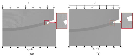
Figure 3.
The boundary conditions and finite element models: (a) is model A; (b) is model B.
The problem is implemented in an axisymmetric formulation using the finite element method. An axisymmetric four-nodal finite element is used. Gradient condensation of elements to the contact areas is implemented. The antifriction layer is divided into 16 elements in thickness. The convergence analysis of the numerical solution on the degree of system discretization was performed earlier [20].
The commercial package of engineering analysis ANSYS Mechanical APDL (ANSYS Inc., Canonsburg, PA, USA) was used to implement the task.
Contact boundary conditions are described in [60]. The paper considered a surface-to-surface contact with an unknown pattern of the distribution of contact state statuses (adhesion, sliding, no contact). The contact interaction is implemented taking into account friction along the mating surfaces. The elements contact pair CONTA171 and TARGE169 is used. “Close gap” is the initial settings of contact elements. Augmented Lagrangian method is contact computation method.
The model parametrization process was carried out to automate numerical calculations. Parameterization parameters: interlayer thickness, inclination angle of the antifriction layer end face, position of the interlayer relative to the steel plate, etc.
The problem solution is based only on the operational requirements for structures. A number of studies aimed at solving the optimization problem are planned to be carried out in the future.
Comparison of the contact stress-strain state parameters of structures is carried out according to the formula (1), where the data of model A are chosen as the reference values:
where and are respectively the values of the compared parameters of models A and B. The comparison parameters: is contact pressure; is contact tangential stress; is normal displacements on ; is structure draft.
3. Results
The bridge bearing are friction units. Contact parameters of elements conjugation zones (contact pressure, contact tangential stress, contact states statuses) are the interest main characteristics. Let’s introduce the notation:
- −
- “pressed surface” is contact surface pressed into steel plates ( in model A, in model B);
- −
- “turning surface” is the contact surface along which the rotation of the spherical segment is possible ( in model A, in model B);
- −
- “end face surface” is relatively free end face of the interlayer ( in model A and B);
- −
- is area that is contact with full adhesion;
- −
- is area of the zone of “no contact” (divergence) of mating surfaces.
Model A with an interlayer in the top steel plate is a classic bearing geometry [19]. Such a bearing geometry is currently quite often used in bridge structures. However, in the future, model B could show better results in the operation of the structure compared to model A. In this regard, the paper is of particular interest in the comparison of bearing performance with different positions of the interlayer relative to the structure steel plates.
The paper [47] presented the distribution pattern of contact parameters and deformation characteristics of the model B mating surfaces. Figure 4 and Figure 5 present the distribution pattern of model A contact parameters. Figure 4 presents a “pressed surface” ( of model A). Figure 5 shows a “turning surface” ( of model A). The following contact parameters are shown in the figures: , contact pressure; , contact tangential stress; r, radius of sliding layer.
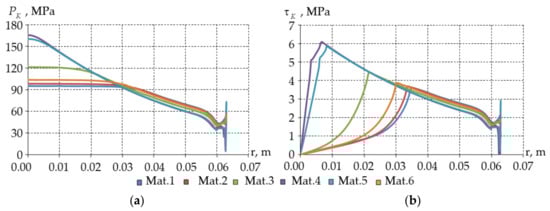
Figure 4.
Contact pressure (a) and contact tangential stress (b) on “pressed surface” model A.
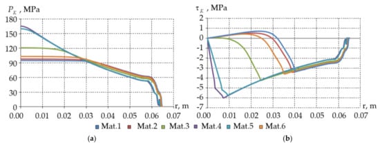
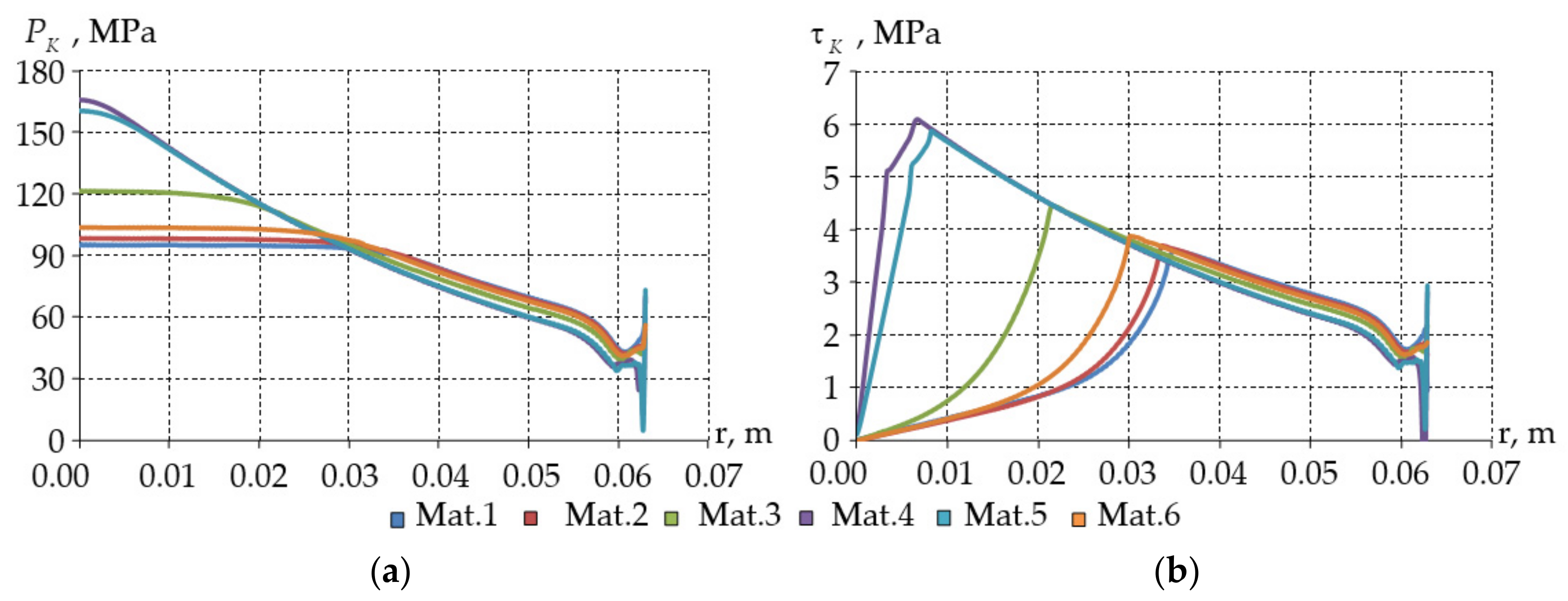
Figure 5.
Contact pressure (a) and contact tangential stress (b) on “turning surface” model A.
The maximum level of contact pressure and contact tangential stress is observed in composite materials (mat. 4–5). The zone of contact surfaces complete “adhesion” is located in the bearing central part. The zone of contact status change from “adhesion” to “sliding” is located in the maximum level of contact tangential stress of polymer layers (mat. 1, 2, 3, 6). The distribution pattern of the contact states statuses is different for interlayers from composite materials (mat. 4–5). The zone of complete “adhesion” is minimal for composite materials (mat. 4–5). The zone of contact status change “adhesion”—“sliding” occurs at the points of change in the law of increase in the contact tangential stress. Such a difference is observed only in model A. Small differences in contact parameters are observed for interlayers of materials 1, 2, and 6: the percentage of the mating surface is in the “adhesion” state is maximum, i.e., materials work within the framework of the elasticity theory on a larger volume of the antifriction layer; the and is minimal.
Table 2 shows a comparison of the contact characteristics of the “pressed surface” for two variants of the structure geometry.
Table 2.
Comparison of the maximum level of contact pressure and tangential stress on “pressed surface”.
is lower than by an average of 27 and 29 times in models A and B, respectively. At the same time, the maximum level of contact parameters of model B is much lower than that of model A. The greatest influence of the interlayer position during the structure deformation is on the contact tangential stress. The maximum influence of the interlayer position on is observed in structures with a sliding layer from composite materials (mat. 5–6). The materials are subject to plastic flow, which affects the geometry of the end face.
The distribution pattern and comparison of the contact parameters of structures along the “turning surface” (Figure 5, Table 3 and Table 4) are of great interest. , , and areas of contact “adhesion” and “no contact” are considered. The results are presented on the example of model A (Figure 5).
Table 3.
Comparison of the maximum level of contact pressure and tangential stress on “turning surface”.
Table 4.
Contact state on “turning surface” models.
The distribution pattern of the contact pressure over the “turning surface” is identical to the “pressed surface”. The interlayer position also does not affect the pattern of the contact pressure distribution. Ref. [26] considered comparison of the distribution pattern of contact parameters on the example of a layer from modified PTFE. Contact tangential stresses of structures with layers of composite materials (mat. 4–5) are negative over the entire “turning surface” area. The contact status change zone “adhesion”—“sliding” is located at the points of change in the law of increase in the contact tangential stress. This effect is not observed in structures with interlayers of polymeric materials. The “no contact” zone near the end face is observed in model A at ° for all variants of the interlayer material.
The maximum level of contact parameters on the “turning surface” is comparable in terms of values with the “pressed surface”. The maximum parameters level is observed in structures with layers of composite materials (mat. 4–5). is lower than by an average of 28 and 27 times in models A and B, respectively. The maximum level of contact parameters of model B is much lower than that of model A. The interlayer position on the “turning surface” has the greatest influence on the contact pressure. Differences on the “turning surface” are minimal in the design with a layer of modified PTFE (mat. 6), less than 1%.
Model A has more than model B for half of the interlayer materials (mat. 1, 2, 6). The mating surfaces divergence is observed for all interlayer materials near the end face of the sliding layer. This effect is associated with deformation of the relatively free end face of the interlayer. The redistribution of contact pressure and contact tangential stress occurs when a zone of “no contact” appears. This leads to an increase in the contact parameters maximum level in the bearing center (model A). The “no contact” zones are not observed in model B for structures with interlayers of polymeric materials (mat. 1–3, 6). The “no contact” zone is observed in structures with interlayers of composite materials (mat. 4–5) on 4.44–5.17% of the mating surface.
The contact parameters of the main mating surfaces depend on the deformation relative to the free end face of the interlayer. Changing the contact parameters of the end face is not informative. Displacements along the surface normal are the main indicator of the structure performance (Figure 6).
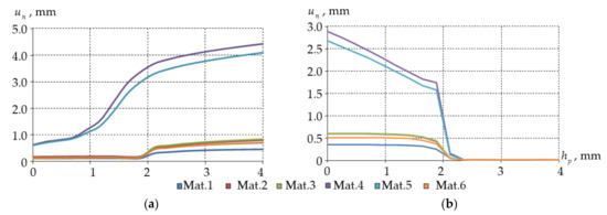
Figure 6.
Normal displacements (b) on : (a) is model A; (b) is model B.
The end face of the interlayer model A is more prone to deformation. The interlayer material flows out of the bearing steel part, which leads to a significant level of deformation. The possibility of cutting off the interlayer material part arises in this case. Normal displacements of less than 1 mm are observed in structures with interlayers of polymeric materials (mat 1–3, 6). Interlayers from composite materials are more susceptible to deformation. A similar pattern is also observed in model B: the level of displacement along the normal of the interlayers end face from composite materials is much greater than that of polymer interlayers. The interlayer material remains in 100% contact with the recess in the structure of the lower steel plate.
Table 5 presents a comparison of the maximum level of displacement along the normal “end face surface”.
Table 5.
Comparison of the maximum level normal displacement of the anti-friction layer end.
The maximum displacements along the normal “end face surface” of model B are 20% or more lower than those of model A. The normal displacement “end face surface” interlayer from composite materials is more than 4 mm in model A, which is comparable to the antifriction layer thickness. The “no contact” zones on the contact surface are observed in model A, which leads to a decrease in the structure performance.
AlfaTech LLC has developed an original experimental setting. The setting allows you to create conditions as close as possible to the structure stress-strain state in the bridge span. The scientists investigated the bearing with a layer of modified PTFE (mat. 6) located in the lower steel plate (model B). It is established that the numerical simulation error from the experiment on the structure draft () was 13.67%. The model draft is less than in the experiment. Table 6 shows an analysis of the influence of materials and the location of the interlayer on the bearing operation in terms of structural draft.
Table 6.
Draft of bearing under different interlayer locations.
The model A draft is greater than that of model B. This effect is associated with a significant deformation of the “end face surface”. The maximum draft of structures is observed when using interlayers from composite materials (mat. 4–5).
The influence of the inclination angle “end face surface” on the structure operation will be considered further. The influence of the inclination angle of the end face on the contact parameters of the “turning surface” (Figure 6, Table 7 and Table 8), displacement along the normal “end face surface” (Figure 7, Table 9), and the structure draft (Table 10) is of the greatest interest.
Table 7.
Comparison of the maximum level of contact pressure and tangential stress under different .
Table 8.
Contact state on “turning surface” models under different .
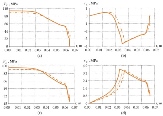
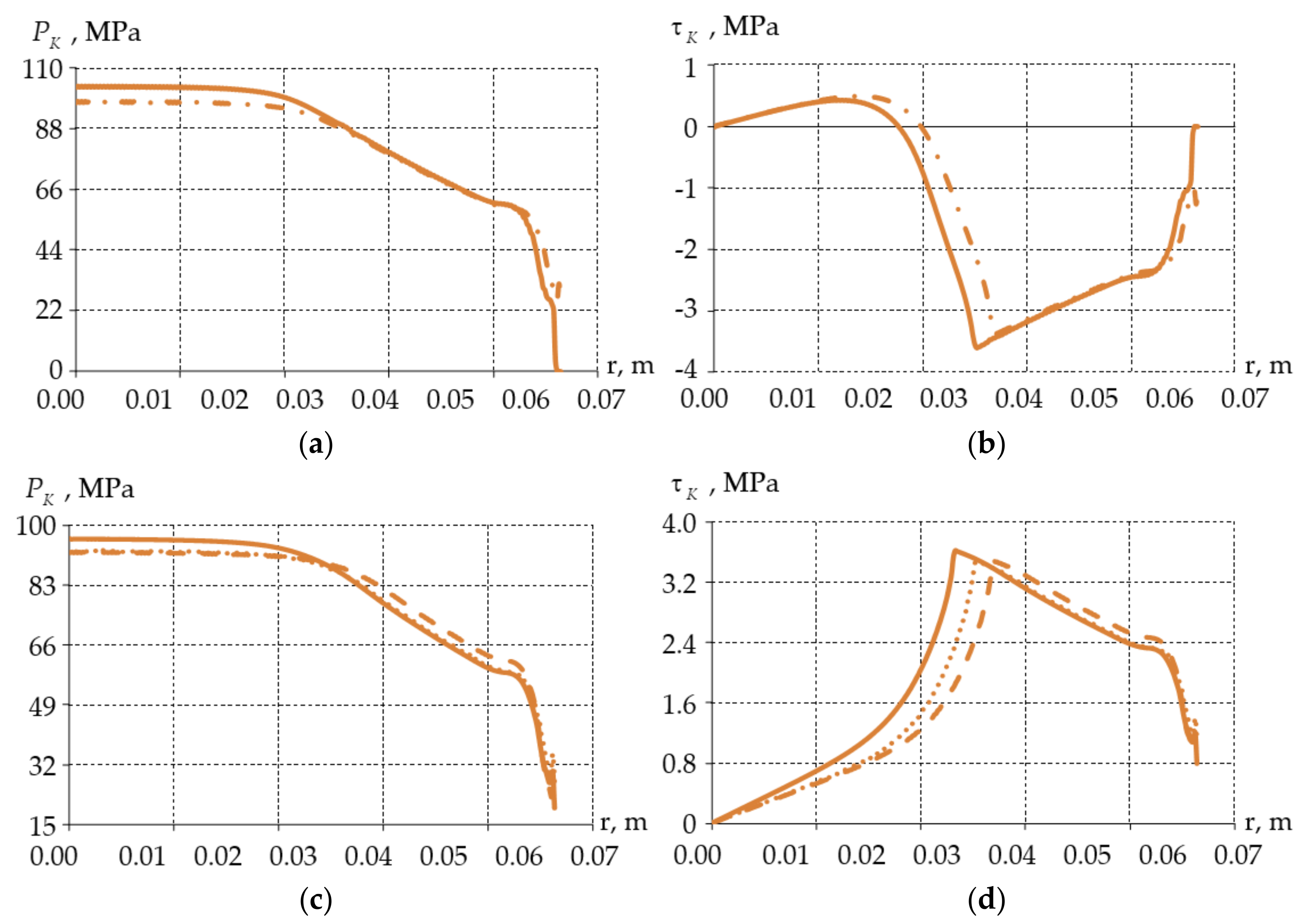
Figure 7.
Contact pressure (a,c) and contact tangential stress (b,d) on turning surface: (a,b) is model A; (c,d) is model B; solid line is °; dash-dotted line is °; points is °; dotted line is °.
Table 9.
Comparison of the maximum level displacements along the normal “end face surface” under different .
Table 10.
Draft of bearing under different .
Figure 7 presents the distribution pattern of contact pressure and contact tangential stress on the example of the layer from modified PTFE (mat. 6).
Changing the inclination angle of the end face of the interlayer made it possible to obtain a number of positive effects for most sliding layer materials:
- −
- an increase in the area of full “adhesion” of mating surfaces;
- −
- lowering the maximum level of contact parameters;
- −
- absence of “no contact” zone near the end face of the model A layer.
Changing the inclination angle of the end face made it possible to reduce the maximum level of contact materials for most materials (except mat. 2). and decreased in model A by 4.5–24.7 and 5.6–26.1%, respectively. and decreased in model B on average by 3.5–15.5 and 3.1–14.6%, respectively. An end face angle of 25° allows to reduce the contact parameters maximum level more than an angle of 40°. This effect is not observed in structures with a UHMWPE interlayer made in Germany (mat 2). An increase in the contact parameters maximum level is observed in interlayers from mat. 2. and increased in model A by 2.04 and 2.28%, respectively. and increased in model B on average by 2.6 and 1.5%, respectively.
Changing the inclination angle of the end face made it possible to increase the “adhesion” area of mating surfaces for most materials (except mat. 2). A decrease in the mating surface percentage in status “adhesion” area is observed in interlayers from mat. 2. The “no contact” zones are not observed in structures with interlayers from polymeric materials (mat. 1–3, 6) in model A at °. The percentage of the “no contact” area of the mating surfaces has significantly decreased in structures with interlayers from composite materials at “rational” .
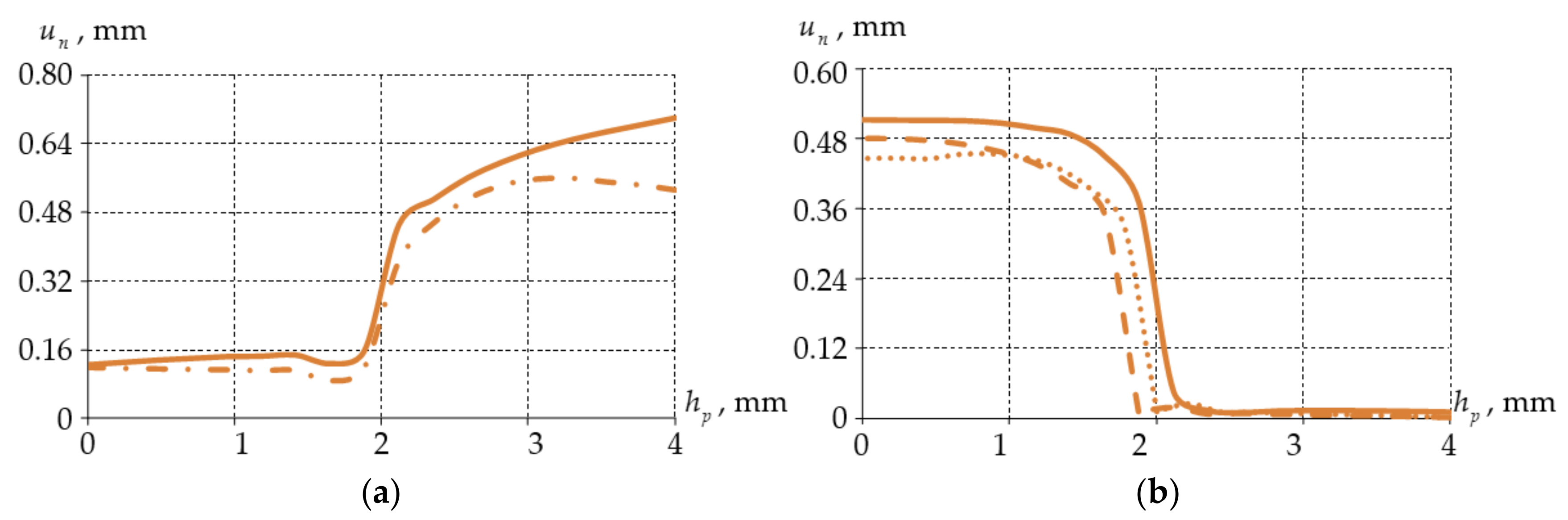
Figure 8 shows displacements along the normal “end face surface” with a layer of modified PTFE as an example.
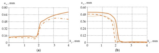
Figure 8.
Normal displacements (b) on : (a) is model A; (b) is model B; solid line is °; dash-dotted line is °; points is °; dotted line is °.
A decrease in the maximum level of displacements along the normal “end face surface” for “rational” was observed.
The maximum decrease in is observed in model A with a layer from composite materials (mat. 4–5) and reaches more than 40% at an angle of 0°. The maximum decrease in is observed in model B at an angle of 25° with a sliding layer from composite materials and reaches more than 20%. The inclination angle of the end face has a minimal effect on the mat. 1 and 2 (UHMWPE). By an angle of 25°, became less than at a standard angle by less than 2%. The average decrease in the level compared to the interlayer with a standard end face angle is 10–25% in other cases.
A draft increase is observed in model B at an end face inclination angle of 40° in interlayers from mat. 1, 6 and reaches 3.3%. The draft level increasing in bearing with interlayers from mat. 3 is observed in model B when the standard inclination angle of the end face is changed. The maximum draft decrease is observed when changing the inclination angle of the end face in structures with layers from composite materials and reaches more than 20% and 10% in models A and B, respectively. Structures with interlayers from polymeric materials (mat 1–3 and 6) showed a comparable draft with a change in the inclination angle of the end face, i.e., the materials of interlayer begin to work in the design with small differences.
4. Discussion
4.1. The Compared Results to PTFE Interlayer
Pure PTFE has not considered in the scientific group studies as a sliding layer of the bearing since 2013. The material was excluded from the most promising sliding layer materials set by the bearing manufacturer AlfaTech LLC. Paper [48] reflected the limitations of its use in friction units, too. However, articles [56,57,58] noted a number of modern scientific studies of the behavior of the bridges bearing with pure PTFE interlayers. Interest in the deformation of spherical bearings considered in this article has arisen, specifically pertaining to models with a layer of pure PTFE. Table 11 presents the study results.
Table 11.
Deformation of pure PTFE interlayers.
The maximum levels of contact pressure and contact tangential stress of structures with a PTFE interlayer are much higher than those from modern sliding layer materials. With displacements along the normal of the end face of the sliding layer, the draft and the “no contact” area of “turning surface” of structure are also maximum. Plastic flow of material from the recess of lower plate is observed when using a layer of pure PTFE in Model B. The authors [48] obtained confirmation of data on the limited use of PTFE.
The behavior of composite materials is closest to pure PTFE. Thus, the insertion of reinforcing elements into the PTFE matrix slightly improved the physical and mechanical properties of the material. The question of the influence of the reinforcing elements on the structure steel elements is interesting. Bronze inclusions can act as an abrasive when the interlayer is deformed, which will lead to defects in polished mating surfaces.
The results presented in this article have an important place in the development of bridge building. They reflect the work comparison of different spherical bearing geometries of bridges. Information about bearings with different interlayer locations in steel plates of structures was presented by Eggert et al. as early as 1974 [41]. However, a work comparison of such structures as performed by the authors of this article was not found in open sources. The current study results showed that bearings with an interlayer pressed into the lower steel plate (Model B) better absorb the vertical loads from the bridge span.
The authors implemented the work comparison of a modern polymer and composite set as an antifriction layer of bearing, too. The data are of practical importance. The research is aimed at collecting a database on the interlayers from different material deformations. The conclusion made is based on the work results and studies performed earlier [33,47,49,56,57,58], namely that at the moment the most promising materials as an interlayer are mat. 2 and 6. Material 1 is not considered as more promising due to the lack of the possibility of its production on an industrial scale. The technological process development has led to the permanent creation of new antifrictional materials and composites [50,61]. LLC “AlfaTech” is constantly searching and undertaking experimental analyses of new materials suitable as sliding layers of bearings.
4.2. About Materials
Polytetrafluoroethylene (PTFE) or Teflon has been discovered in 1938 by R. J. Plunkett [62]. The material is widely used as protective and antifriction coatings and interlayers [45,50,51,58,59]. The characteristics and properties of PTFE are improved in composite forms of material with various fillers according to Dhanumalayan et al. [48] and Wang et al. [63]. Bronze inclusions and molybdenum disulphide have been used to improve the properties of PTFE and produce a ground surface with a low friction coefficient [48].
PTFE composites with various bronze inclusions and molybdenum disulphide have a free compression modulus 58–65% higher than that of pure PTFE which was established in our work. The constrained compression modulus of composites with dendritic inclusions is lower by 3.4%, with spherical ones it is higher by 7.45%. Poisson’s ratios are 4–6% lower. Elastic-plastic strain of 10% occurs in composites with dendritic and spherical bronze inclusions at stresses 37% and 44.6% higher than in pure PTFE, respectively.
Radiation-modified PTFE has also shown improved mechanical properties in experiments. The free compression modulus was 58.5% higher, the constrained compression modulus was 3.75% higher, the Poisson’s ratio was 1.07% lower, and the stresses at 10% strain were 114.3% higher compared to pure PTFE.
The properties of PTFE and materials derived from them are being investigated quite extensively [63,64,65,66]. The insufficient properties of PTFE and materials based on it for the creation of viscoelastic behavior models were noted in [67]. Pure PTFE, modified PTFE, and PTFE composition with glassfiber and molybdenum disulphide were investigated Tan et al. The mechanical and viscoelastic properties of the materials were obtained. We can only make a qualitative comparison of materials deformation patterns. This is due to the research of materials different in terms of composition and manufacturers. The materials viscoelastic characteristics were also obtained by our scientific group. The deformation qualitative patterns and the value ranges of the mechanical characteristics obtained by us are similar to the results of Tan et al. The dependences of the deformation and mechanical characteristics obtained in the framework of the work visually correlate with the results of other authors [64,65,66]. Now, our group is engaged in the description of the materials viscoelastic behavior using the Prony rows. The material viscoelastic model will become an addition to the elastic-plastic model in further studies of the bearings when simulating dynamic, cyclic, and temperature loads.
The improved characteristics of PTFE composites and their modifications were also confirmed during the antifriction layer deformation of the bearings for all variants of its geometric configuration.
A large set of modern polymers and composites that can be used in friction units exists at present [50,54,61,68]. These are polyether ether ketone (PEEK), polymethylmethacrylate (PMMA), polyurethane (PU), polyamide (PA), UHMWPE, and composites based on them [69]. UHMWPE ROBO®SLIDE [70] and MSM [71] are used as sliding layers by MAGEBA and MAURER, respectively. These materials have improved properties compared to PTFE according to the data of manufacturers. The UHMWPE improved properties compared to other polymers have been confirmed by studies [72]. Research was conducted on a limited number of characteristics. Studies also could not include the entire volume of modern polymers. In our case, pure UHMWPE showed deformation and contact characteristics having little difference from the modified PTFE according to the results of experiments and numerical studies. Alfatech LLC and our research team singled out and modified PTFE as the most promising material for antifriction layers of bearings.
The search for modern antifriction materials and composites of Russian and foreign production with improved thermomechanical properties continues. It is necessary to analyze the available mechanical properties of PEEK, PMMA, PU, and PA in order to assess the possibility of their use in bearings. PEEK in its pure form has sufficiently high wear rates and friction coefficients according to [68,69,73]. At the same time, compositions based on it have improved characteristics [68]. This fact is very similar to the data for PTFE. Conclusions can be drawn that affirm the study of modern, including in real structures.
5. Conclusions
The influence of the antifriction layer location in the spherical bearings of six materials of the sliding layer was considered in this study. It has been established that the bearing with a layer pressed into the spherical segment (model A, the bearing classical geometry) has a number of disadvantages compared to the design with a layer placed in lower steel plate (model B):
- −
- a higher level of maximum parameters on all interfaces of steel plates of structure with an interlayer;
- −
- the “no contact” zones on the “turning surface”;
- −
- the maximum level of displacements along the normal to the “end face surface” is greater;
- −
- the plastic flow of interlayer materials from the steel plate recess, material shearing during the structure operation is possible;
- −
- the draft level of the structure is greater.
The deformation behavior features of model A are observed for all variants of the interlayer material. Interlayers from composite materials (mat. 4–5) are subject to the greatest deformation.
Improvement in the structure operation regardless of the sliding layer location is observed when the standard inclination angle of the end face is changed to “rational”:
- −
- the reduction of the maximum level of contact and deformation characteristics;
- −
- the increase in the “adhesion” area of mating surfaces: the volume of the interlayer material working within the framework of the elasticity theory increases;
- −
- the absence of a “no contact” zone in interlayer from polymeric materials (mat. 1–3, 6) or a decrease in % of the “no contact” area in interlayer from composites (mat. 4–s5).
Moreover, the following could be distinguished from the data obtained:
- −
- The construction with a layer placed in lower steel plate shows better performance compared to model A.
- −
- Interlayers from materials 1, 2, and 6 show a better distribution of contact parameters compared to other materials.
- −
- The constructions that have an inclination angle of the end face of 0° for model A and 25° for model B have more distributed contact parameters and lower draft values. Thus, it may be concluded that structures with these angles perform better than those with standard angles.
Future studies ought to assess the influence of the position and geometry bearing, taking into account the technological recesses in the sliding layer as well the horizontal and cyclic loads.
Author Contributions
Conceptualization, A.A.A., A.A.K., A.P.P. and V.I.S.; methodology, A.A.K.; software, A.A.K., A.P.P. and V.I.S.; validation, A.A.A. and A.A.K.; writing—original draft preparation, A.A.K., A.P.P. and V.I.S.; writing—review and editing, A.A.A., A.A.K. and A.P.P.; visualization, A.A.K., A.P.P. and V.I.S.; funding acquisition, A.A.K. All authors have read and agreed to the published version of the manuscript.
Funding
The study supported by a grant of Russian Science Foundation (project No. 22-29-01313).
Institutional Review Board Statement
Not applicable.
Informed Consent Statement
Not applicable.
Data Availability Statement
Not applicable.
Acknowledgments
Not applicable.
Conflicts of Interest
The authors declare no conflict of interest.
Nomenclature
| inclination angle of the antifriction layer end face; | |
| antifriction layer thickness; | |
| central section height of the upper steel plate; | |
| central section height of the lower steel plate; | |
| structure height; | |
| maximum length of bearing half; | |
| maximum length of bearing; | |
| upper surface of the steel plate; | |
| lower surface of the steel plate; | |
| vertical force applied to ; | |
| pressure; | |
| upper contact surface; | |
| lower contact surface; | |
| antifriction layer end face; | |
| contact pressure; | |
| maximum contact pressure; | |
| maximum contact pressure for the “turning surface”; | |
| relative difference of contact pressure of models A and B; | |
| contact tangential stress; | |
| maximum modulo contact tangential stress; | |
| maximum modulo contact tangential stress for the “turning surface”; | |
| relative difference of maximum modulo contact tangential stress of models A and B; | |
| normal displacements on ; | |
| maximum normal displacements on ; | |
| maximum normal displacements on ; | |
| relative difference of maximum normal displacements on of models A and B; | |
| structure draft; | |
| relative difference of structure draft of models A and B; | |
| area that is contact with full adhesion; | |
| area that is contact with full adhesion for the “turning surface”; | |
| area of the zone of “no contact” (divergence) of mating surfaces; | |
| area of the zone of “no contact” (divergence) of mating surfaces for the “turning surface”. |
References
- Arêde, A.; Costa, C. Proceedings of ARCH 9th International Conference on Arch Bridges; Springer: Cham, Switzerland, 2019. [Google Scholar] [CrossRef]
- Vayas, I.; Liopoulos, A. Design of Steel-Concrete Composite Bridges to Eurocodes; CRC Press: Boca Raton, FL, USA, 2013. [Google Scholar]
- Vaidya, S.M. Bridge Bearings; Railways Institute of Civil Engineering: Pune, India, 2014.
- Frangopol, D.M.; Dong, Y.; Sabatino, S. Bridge life-cycle performance and cost: Analysis, prediction, optimisation and decision-making. Struct. Infrastruct. Eng. 2017, 13, 1239–1257. [Google Scholar] [CrossRef]
- Xie, H.-B.; Wu, W.-J.; Wang, Y.-F. Life-time reliability based optimization of bridge maintenance strategy considering LCA and LCC. J. Clean. Prod. 2018, 176, 36–45. [Google Scholar] [CrossRef]
- Wu, C.; Wu, P.; Wang, J.; Jiang, R.; Chen, M.; Wang, X. Critical review of data-driven decision-making in bridge operation and maintenance. Struct. Infrastruct. Eng. 2020, 18, 47–70. [Google Scholar] [CrossRef]
- Calvert, G.; Neves, L.; Andrews, J.; Hamer, M. Incorporating defect specific condition indicators in a bridge life cycle analysis. Eng. Struct. 2021, 246, 113003. [Google Scholar] [CrossRef]
- Peel, H.; Luo, S.; Cohn, A.; Fuentes, R. Localisation of a mobile robot for bridge bearing inspection. Autom. Constr. 2018, 94, 244–256. [Google Scholar] [CrossRef]
- Petcherdchoo, A.; Neves, L.A.; Frangopol, D.M. Optimizing Lifetime Condition and Reliability of Deteriorating Structures with Emphasis on Bridges. J. Struct. Eng. 2006, 134, 544–552. [Google Scholar] [CrossRef]
- Higuchi, S.; Macke, M. Cost-benefit analysis for the optimal rehabilitation of deteriorating structures. Struct. Saf. 2008, 30, 291–306. [Google Scholar] [CrossRef]
- Colford, B.; Chiarello, M.; Hendy, C.; Sandberg, J. Bearing replacement and strengthening of Forth road bridge approach viaducts. In Proceedings of the Sixth International IABMAS Conference, Lake Como, Italy, 8–12 July 2012; pp. 81–92. [Google Scholar] [CrossRef]
- Redpath, J. Pendel bearing replacement at A9 Kessock Bridge, Scotland. In Proceedings of the Institution of Civil Engineers-Bridge Engineering; Thomas Telford Ltd.: London, UK, 2007; Volume 160, pp. 195–203. [Google Scholar] [CrossRef]
- Ma, F.; Cheng, X.; Zhu, X.; Wu, G.; Feng, D.-C.; Hou, S.; Kang, X. Safety Monitoring of Bearing Replacement for a Concrete High-Speed Railway Bridge Based on Acoustic Emission. J. Perform. Constr. Facil. 2022, 36, 04022014. [Google Scholar] [CrossRef]
- Proske, D. Bridge Collapse Frequencies Versus Failure Probabilities; Springer: Cham, Switzerland, 2018. [Google Scholar] [CrossRef]
- Beben, D. Soil-Steel Bridges; Springer: Cham, Switzerland, 2020. [Google Scholar] [CrossRef]
- Ye, S.; Lai, X.; Bartoli, I.; Aktan, A.E. Technology for condition and performance evaluation of highway bridges. J. Civ. Struct. Health Monit. 2020, 10, 573–594. [Google Scholar] [CrossRef]
- Deng, Y.; Li, A. Structural Health Monitoring for Suspension Bridges; Springer: Singapore, 2019. [Google Scholar] [CrossRef]
- Okamoto, N.; Kinoshita, T.; Futagi, T. Development of new embedded expansion joint using high flexibility stone mastic asphalt. In International Symposium on Testing and Characterization of Sustainable and Innovative Bituminous Materials; Springer: Dordrecht, The Netherlands, 2016; Volume 11, pp. 837–849. [Google Scholar] [CrossRef]
- Eggert, H.; Kauschke, W. Structural Bearings; Ernst & Sohn: Berlin, Germany, 2002. [Google Scholar]
- Kamenskih, A.; Trufanov, N. Numerical analysis of the stress state of a spherical contact system with an interlayer of antifriction material. Comput. Contin. Mech. 2013, 6, 54–61. [Google Scholar] [CrossRef]
- Jiang, L.; He, W.; Wei, B.; Wang, Z.; Li, S. The shear pin strength of friction pendulum bearings (FPB) in simply supported railway bridges. Bull. Earthq. Eng. 2019, 17, 6109–6139. [Google Scholar] [CrossRef]
- Kuznetsov, D.N.; Grigorash, V.V.; Sventikov, A.A. Work power of the support unit of the steel I-beam. Russ. J. Build. Constr. Arch. 2021, 1, 19–29. [Google Scholar] [CrossRef]
- Kim, S.; Kim, T. Machine-learning-based prediction of vortex-induced vibration in long-span bridges using limited information. Eng. Struct. 2022, 266, 114551. [Google Scholar] [CrossRef]
- Pipinato, A. Innovative Bridge Design Handbook; Elsevier: Oxford, UK, 2021. [Google Scholar] [CrossRef]
- Blinkin, M.; Koncheva, E. Transport Systems of Russian Cities: Ongoing Transformations; Springer: Cham, Switzerland, 2016. [Google Scholar] [CrossRef]
- Wetzk, V. Brückenlager. 1850–1950. Ph.D. Thesis, Brandenburgische Technische Universität Cottbus-Senftenberg, Cottbus, Germany, 25 November 2010. [Google Scholar]
- Huang, X.; Hou, S.; Liao, M.; Zhu, Z. Bearing Capacity Evaluation and Reinforcement Analysis of Bridge Piles under Strong Earthquake Conditions. KSCE J. Civ. Eng. 2018, 22, 1295–1303. [Google Scholar] [CrossRef]
- Devitofranceschi, A.; Paolieri, E. Integral Bridges: A Construction Method to Minimize Maintenance Problems. Lect. Notes Civ. Eng. 2020, 42, 515–529. [Google Scholar] [CrossRef]
- Huang, W.; Pei, M.; Liu, X.; Wei, Y. Design and construction of super-long span bridges in China: Review and future perspectives. Front. Struct. Civ. Eng. 2020, 14, 803–838. [Google Scholar] [CrossRef]
- Su, M.; Wang, J.; Peng, H.; Cai, C.S.; Dai, G. State-of-the-art review of the development and application of bridge rotation construction methods in China. Sci. China Technol. Sci. 2020, 64, 1137–1152. [Google Scholar] [CrossRef]
- Kollegger, J.; Reichenbach, S. Balanced Lift Method—Building Bridges without Formwork. Lect. Notes Civ. Eng. 2018, 10, 200–215. [Google Scholar] [CrossRef]
- Yu, X.-M.; Chen, D.-W.; Bai, Z.-Z. A New Method for Analysis of Sliding Cable Structures in Bridge Engineering. KSCE J. Civ. Eng. 2018, 22, 4483–4489. [Google Scholar] [CrossRef]
- Adamov, A.A.; Kamenskih, A.A.; Pankova, A.P. Numerical analysis of the spherical bearing geometric configuration with antifriction layer made of different materials. PNRPU Mech. Bull. 2020, 4, 15–26. [Google Scholar] [CrossRef]
- Ono, K. Structural materials: Metallurgy of bridges. In Metallurgical Design and Industry; Springer: Cham, Switzerland, 2018; pp. 193–269. [Google Scholar] [CrossRef]
- Zhang, Y.; Li, J. Effect of Material Characteristics of High Damping Rubber Bearings on Aseismic Behaviors of a Two-Span Simply Supported Beam Bridge. Adv. Mater. Sci. Eng. 2020, 2020, 9231382. [Google Scholar] [CrossRef]
- Liang, H.; Zhang, Y.; Wang, W. Influence of the cage on the migration and distribution of lubricating oil inside a ball bearing. Friction 2022, 10, 1035–1045. [Google Scholar] [CrossRef]
- Choi, E.; Lee, J.S.; Jeon, H.-K.; Park, T.; Kim, H.-T. Static and dynamic behavior of disk bearings for OSPG railway bridges under railway vehicle loading. Nonlinear Dyn. 2010, 62, 73–93. [Google Scholar] [CrossRef]
- Itoh, Y.; Gu, H.S. Prediction of Aging Characteristics in Natural Rubber Bearings Used in Bridges. J. Bridge Eng. 2009, 14, 122–128. [Google Scholar] [CrossRef]
- Beyer, E.; Wintergerst, L. New bridge storage, new pillar shape. Bauingenleur 1960, 35, 227–230. [Google Scholar]
- Block, T.; Eggert, H.; Kauschke, W. Lager im Bauwesen; John Wiley & Sons: New York, NY, USA, 2015. [Google Scholar] [CrossRef]
- Eggert, H.; Grote, J.; Kauschke, W. Lager im Bauwesen; Ernst & Sohn: Berlin, Germany, 1974. [Google Scholar]
- Wei, W.; Yuan, Y.; Igarashi, A.; Zhu, H.; Luo, K. Generalized hyper-viscoelastic modeling and experimental characterization of unfilled and carbon black filled natural rubber for civil structural applications. Constr. Build. Mater. 2020, 253, 119211. [Google Scholar] [CrossRef]
- Sánchez, M.A.G.; Giraldo-Vásquez, D.H.; Sánchez, R.M. Rheometric, transient, and cyclic tests to assess the viscoelastic behavior of natural rubber-based compounds used for rubber bearings. Mater. Today Commun. 2020, 22, 100815. [Google Scholar] [CrossRef]
- Yuan, Y.; Wang, S.; Tan, P.; Zhu, H. Mechanical performance and shear constitutive model study of a new high-capacity polyurethane elastomeric bearing. Constr. Build. Mater. 2020, 232, 117227. [Google Scholar] [CrossRef]
- Niemierko, A. Modern Bridge Bearings and Expansion Joints for Road Bridges. Transp. Res. Procedia 2016, 14, 4040–4049. [Google Scholar] [CrossRef]
- Askari, E.; Flores, P. Coupling multi-body dynamics and fluid dynamics to model lubricated spherical joints. Arch. Appl. Mech. 2020, 90, 2091–2111. [Google Scholar] [CrossRef]
- Adamov, A.A.; Kamenskikh, A.A.; Pankova, A.P. Influence Analysis of the Antifriction Layer Materials and Thickness on the Contact Interaction of Spherical Bearings Elements. Lubricants 2022, 10, 30. [Google Scholar] [CrossRef]
- Dhanumalayan, E.; Joshi, G.M. Performance properties and applications of polytetrafluoroethylene (PTFE)—A review. Adv. Compos. Hybrid. Mater. 2018, 1, 247–268. [Google Scholar] [CrossRef]
- Sadovskaya, N.V.; Obvintsev, A.Y.; Khatipov, R.S.; Seliverstov, D.I.; Khatipov, S.A. Effect of irradiation on interfacial interaction and structure formation in filled PTFE composites. J. Surf. Investig. X-ray Synchrotron Neutron Tech. 2016, 10, 917–924. [Google Scholar] [CrossRef]
- Yi, X.; Du, S.; Zhang, L. Composite Materials Engineering, Volume 1: Fundamentals of Composite Materials; Springer: Singapore, 2018. [Google Scholar] [CrossRef]
- Wang, Q.J.; Chung, Y.W. Encyclopedia of Tribology; Springer: Boston, MA, USA, 2013. [Google Scholar] [CrossRef]
- Martynov, M.A.; Gol’Dman, A.Y.; Il’Chenko, P.A.; Polyakov, Y.S.; Andreeva, A.I. Effect of thermal treatment on the mechanical properties and accumulation of submicrocracks in fluoroplastics. Strength Mater. 1975, 7, 1390–1393. [Google Scholar] [CrossRef]
- Pavlenko, V.I.; Bondarenko, G.G.; Tarasov, D.G.; Edamenko, O.D. Gamma modification of radiation-resistant fluoroplastic composite. Inorg. Mater. Appl. Res. 2013, 4, 389–393. [Google Scholar] [CrossRef]
- Shelestova, V.A.; Grakovich, P.N.; Danchenko, S.G.; Smirnov, V.A. New antifriction materials of the Fluvis group based on modified carbon fibers. Chem. Pet. Eng. 2006, 42, 663–666. [Google Scholar] [CrossRef]
- Balyakin, V.B.; Khatipov, S.A.; Pilla, C.K. Experimental studies of tribotechnical characteristics of radiation-modified polytetrafluoroethylene to use in rotor supports. J. Frict. Wear 2015, 36, 346–349. [Google Scholar] [CrossRef]
- Adamov, A.; Kamenskikh, A.; Strukova, V. Numerical analysis of the effect of the antifriction layer face angle on the deformation behavior of spherical support parts of different geometric configurations. AIP Conf. Proc. 2021, 2371, 020004. [Google Scholar] [CrossRef]
- Adamov, A.A.; Kamenskikh, A.A.; Strukova, V.I. Influence of geometry and configuration of the spherical sliding layer of bridge bearings on the structure working capacity. Comput. Contin. Mech. 2021, 14, 289–299. [Google Scholar] [CrossRef]
- Gajewski, M.D.; Miecznikowski, M. Assessment of the Suitability of Elastomeric Bearings Modeling Using the Hyperelasticity and the Finite Element Method. Materials 2021, 14, 7665. [Google Scholar] [CrossRef]
- Heggade, V.N. Bearings & Their Configurations Within Bridge System. Bridge Struct. Eng. 2013, 43, 23–35. [Google Scholar]
- Kamenskih, A.A.; Trufanov, N.A. Regularities interaction of elements contact spherical unit with the antifrictional polymeric interlayer. J. Frict. Wear 2015, 36, 170–176. [Google Scholar] [CrossRef]
- Wang, Q.J.; Chung, Y.W. Antifriction Materials and Composites; Springer: Boston, MA, USA, 2013. [Google Scholar] [CrossRef]
- Gooch, J.W. Encyclopedic Dictionary of Polymers; Springer: New York, NY, USA, 2007. [Google Scholar] [CrossRef]
- Wang, H.; Sun, A.; Qi, X.; Dong, Y.; Fan, B. Experimental and Analytical Investigations on Tribological Properties of PTFE/AP Composites. Polymers 2021, 13, 4295. [Google Scholar] [CrossRef] [PubMed]
- Mnif, R.; Ben Jemaa, M.C.; Kacem, N.H.; Elleuch, R. Impact of Viscoelasticity on the Tribological Behavior of PTFE Composites for Valve Seals Application. Tribol. Trans. 2013, 56, 879–886. [Google Scholar] [CrossRef]
- Zhang, Y.; Xu, S.; Zhang, Q.; Zhou, Y. Experimental and Theoretical Research on the Stress-Relaxation Behaviors of PTFE Coated Fabrics under Different Temperatures. Adv. Mater. Sci. Eng. 2015, 2015, 319473. [Google Scholar] [CrossRef]
- Feng, C.; Zhang, D.; Chen, K. In situ microscopic observations of dynamic viscoelastic contact and deformation at a friction interface. Mater. Express 2019, 9, 235–244. [Google Scholar] [CrossRef]
- Tan, B.; Stephens, L.S. Evaluation of viscoelastic characteristics of PTFE-Based materials. Tribol. Int. 2019, 140, 105870. [Google Scholar] [CrossRef]
- Lin, Z.; Zhang, K.; Ye, J.; Li, X.; Zhao, X.; Qu, T.; Liu, Q.; Gao, B. The effects of filler type on the friction and wear performance of PEEK and PTFE composites under hybrid wear conditions. Wear 2022, 490, 204178. [Google Scholar] [CrossRef]
- Samad, M.A. Recent Advances in UHMWPE/UHMWPE Nanocomposite/UHMWPE Hybrid Nanocomposite Polymer Coatings for Tribological Applications: A Comprehensive Review. Polymers 2021, 13, 608. [Google Scholar] [CrossRef]
- Mageba. Available online: https://www.mageba-group.com (accessed on 20 July 2022).
- Maurer. Available online: https://www.maurer.eu (accessed on 20 July 2022).
- Lampman, S. Characterization and Failure Analysis of Plastics; ASM International: Almere, The Netherlands, 2003. [Google Scholar]
- Friedrich, K. Polymer composites for tribological applications. Adv. Ind. Eng. Polym. Res. 2018, 1, 3–39. [Google Scholar] [CrossRef]


Publisher’s Note: MDPI stays neutral with regard to jurisdictional claims in published maps and institutional affiliations. |
© 2022 by the authors. Licensee MDPI, Basel, Switzerland. This article is an open access article distributed under the terms and conditions of the Creative Commons Attribution (CC BY) license (https://creativecommons.org/licenses/by/4.0/).