Article

Separation and Extraction of Mixed Grinding Chips of Artificial Joints with Different Densities by Multiple Centrifugal Separations

School of Materials Science and Physics, China University of Mining and Technology, Xuzhou 221116, China
*
Authors to whom correspondence should be addressed.
These authors contributed equally to this work.
Lubricants 2022, 10(9), 226; https://doi.org/10.3390/lubricants10090226
Submission received: 14 August 2022 / Revised: 9 September 2022 / Accepted: 15 September 2022 / Published: 19 September 2022
(This article belongs to the Special Issue State-of-the-Art of Tribology in China)

Abstract

:
Aseptic loosening caused by the wear and tear of the artificial joint prosthesis after implantation is one of the main causes of artificial joint failure. Therefore, it is important to investigate the wear debris generated due to wear when developing new artificial joint materials. Aseptic loosening is related to the size, number, and morphology of wear debris, and this study proposed the separation and extraction of mixed wear debris with different density ratios of artificial joints by centrifugation to study the characteristics of different artificial joint wear and wear debris extraction rates. The results showed that multiple centrifugations to separate the mixed wear debris were able to reintroduce the wear debris on the wall of the centrifuge tube into the solution and that the wear debris extraction rate was increased. Suspensions with different density ratios of artificially jointed mixed wear debris were effectively separated by this method. The total extraction rate of the three repeated extractions compared to the first extraction rate, the extraction rate of CoCrMo wear debris increased by 6.7%, ultra-high molecular weight polyethylene (UHMWPE) wear debris increased by 15.1–23.44%, ZrO2 wear debris increased by 10.91%, and that of polyether ether ketone (PEEK) wear debris increased by 9.95%. This method for separating and extracting wear debris from artificial joints can realize the separation of mixed wear debris from artificial joints and obtain a high extraction rate and high-quality wear debris images, investigate the wear mechanism of artificial joint implants, and provide valuable information on the wear performance of new artificial joint implants under investigation.

Graphical Abstract

1. Introduction

The artificial joint is implanted in the human body in a complex operating environment, such as the knee joint, where it is submerged in body fluids but also subjected to the effects of the body’s impact and weight. As a result, frictional wear of the joint material after implantation is bound to produce wear debris. Aseptic loosening of the artificial joint caused by wear debris is the main mode of artificial joint failure, with a failure rate of about 10% [1,2,3,4,5]. Abrasive debris of different morphology [6,7,8], size [9,10,11,12], and composition [13,14] reflect different frictional wear mechanisms, and behaviors of artificial joints and can lead to different degrees of biological responses [15,16,17,18]. New artificial joint materials must be investigated for wear debris before they are introduced into the clinic and market [19]. Therefore, the effective separation and extraction of artificial joint wear debris from the lubricating fluid and the characterization and analysis of artificial joint wear debris are one of the key topics in the study of artificial joint materials.
Evaluation of the frictional wear performance of artificial joints is mainly performed in vitro using artificial joint simulators, in which calf serum is usually used as a simulated lubricating fluid [20]. Artificial joint wear produces a mixture of wear debris of different shapes, sizes, and compositions [6,21,22]. The morphological characteristics of the wear debris reflect the complexity of wear, such as UHMWPE granular wear debris, are mainly formed by adhesive wear [23]. Wear debris is often considered to be the typical product of adhesive wear [23]. There are many studies exploring the relationship between UHMWPE wear debris and aseptic loosening [24,25,26]. Extraction and research of mixed wear debris is rarely available. Extraction and characterization of mixed wear debris play an important role in studying the tribological behavior of artificial joints, wear mechanisms, and prolonging their service life, and excellent methods for extracting abrasive chips from the lubricant of artificial joints in vitro wear tests need to be urgently explored.
Artificial joint wear debris scattered in the calf serum lubricating fluid and the surface through the electrostatic effect, hydrophobic effect, hydrophilic effect, and lubricating serum in the protein combination by the multi-layer protein are wrapped to form a protein halo. This poses a great challenge in terms of wear debris count, particle size analysis, and morphological characterization for artificial joint wear tests. Extraction of wear debris includes degradation of proteins and separation of wear debris [23]. Artificial joint wear debris extraction first needs to exclude the interference of proteins or lipids in serum, and degradation of proteins in calf serum is one of the main steps of artificial joint wear debris extraction. Another important step in the extraction of artificial wear debris is the separation and filtration of the mixed wear debris. Artificial joint wear debris is lost with the removed solution during extraction or adheres to the walls of containers, such as centrifuge tubes, which can result in poor extraction rates of artificial joint wear debris. CoCrMo, UHMWPE, and ceramics are the mainstay of research on the extraction of wear debris from artificial joint materials. Only one artificial joint wear debris was extracted, and there is little research on the separation and extraction of new artificial joints such as PEEK and hybrid abrasive chips.
Previous studies on the extraction rate of artificial joint wear debris are only for CoCrMo and ceramics [13,27,28], which are denser and easier to separate and extract from the solution. The extraction rate is low, and there is a lack of studies on the extraction rate of artificial joint wear debris such as PEEK, which are similar to the solution density. Using the traditional artificial joint wear debris extraction method [29], we proposed an extraction method of multiple centrifugal separations for mixed wear debris from artificial joints with different density ratios. This method could separate and extract the mixed wear debris effectively while improving the extraction rate of artificial joint wear debris. The results of the study provide a basis for research on the mechanism of wear debris generation and the wear mechanism of artificial joints.

2. Materials and Methods

2.1. Materials

UHMWPE powder (molecular weight 600 million, Mitsui Chemicals (Shanghai)), PEEK powder (1000 mesh, medical grade, Victrex High Performance Materials Trading (Shanghai) Co., Ltd., Shanghai, China), ZrO2 powder (50 nm, Andi Metal Materials Co., Ltd., Qinghe County, Xingtai, China), and CoCrMo powder were selected as the particles collected for wear experiments. Calf serum (protein concentration 36 mg/mL, Zhejiang Tianhang Biotechnology Company, Hangzhou, China), papain (Aladdin Biochemical Technology Co., Shanghai, China), proteinase K, sodium phosphate (Xilong Science Co., Shantou, China), ethylenediaminetetraacetic acid (EDTA) (Wuxi Yashang Chemical Co., Ltd., Wuxi, China), hydrochloric acid, trihydroxymethylaminomethane (Tris), and mixed grinding chips with different density ratios of artificial joints were also important materials in this study. Different density ratios of the artificial joint mixed grinding chips were prepared according to the artificial joint material, as shown in Table 1.

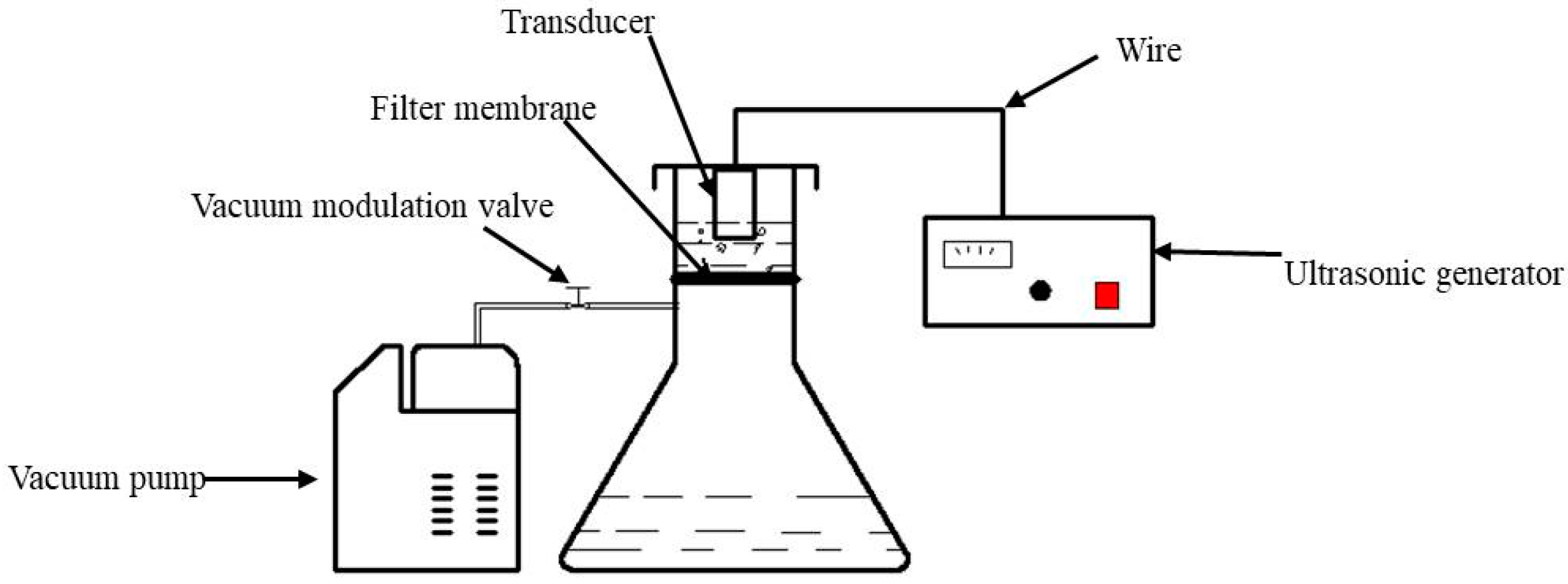
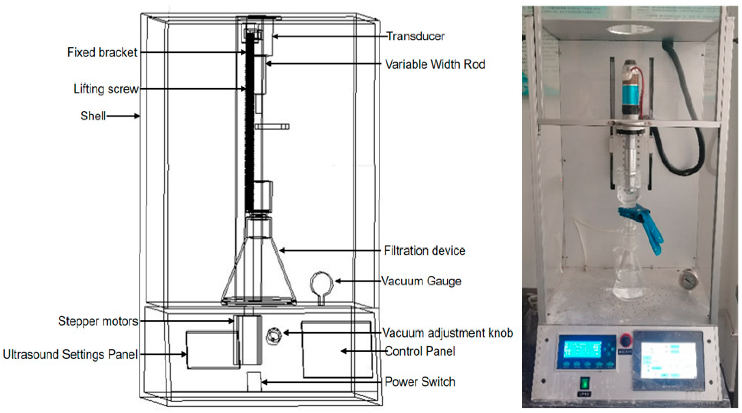
2.2. Experimental Equipment

Combining the theoretical study of ultrasound-assisted artificial joint wear debris extraction and separation and the problems in the grinding chip extraction process, this study independently developed the VN-2 type microparticle and nanoparticle separation and extraction device. The working principle diagrams of the micro-nanoparticle separation and extraction device are shown in Figure 1. Separation and extraction of microscopic and nanoparticles using the VN-2 device is a special bench-type device and consists mainly of an ultrasonic system, a vacuum filtration system, and support components. The schematic diagram and physical photos of the micro-nanoparticle separation and extraction device are shown in Figure 2.

2.3. Calculation of the Settling of Abrasive Chips in a Solution

2.3.1. Settling Velocity of Abrasive Chips in a Stationary Solution

The migration and diffusion of wear debris in degraded calf serum solution is essentially a matter of force and migration of particles in liquid–solid two-phase flow. The forces on the particles in the flow field are complex. If the concentration of particles in the solution is high, the particles are agglomerated by electrostatic forces, van der Waals forces, etc., and fragmentation and reorganization occur during migration and diffusion. If the particle concentration is low, we ignore the interaction of the forces between the particles, consider the particles as individual particles to consider their forces, ignore the effect of shape on particle migration, and simplify the individual particles to the problem of settling of single spherical particles in solution. The force analysis of particles in the flow field with Newton’s second law shows that [29]
m p d u p d t =   F p + m p g  
where mp is the particle mass (kg); up is the particle velocity (m/s); t is the time (s); Fp is the combined force of buoyancy, pressure gradient force, traction force, Basset force, Magnus force, Saffman force, etc. on the particle (N); and mpg is the particle gravity (N). We derive the equation of motion of the particle based on the force on the particle in the vertical direction [30].
m p d u p d t = 1 8 C D π d p 2 ρ u f 1 p 2 1 12 π d p 3 ρ f d u p d t + 1 6 π d p 3 g ( ρ f ρ p )  
ρf is the fluid density (kg/m3), ρp is the particle density (kg/m3), and dp is the diameter of the particle (m). In general, Magnus lift force and Saffman lift force is small in value and can be ignored, and Basset force only works in a very short period of particle motion; therefore, the force is ignored for particle motion analysis in the vertical direction, and CD is the resistance coefficient.
m p = 4 3 π ( 1 2 d p ) 3 ρ p  
Substituting (3) into (2), we obtain
d u p d t = 3 ρ f 4 ρ p d p C d u p 2 ρ f 2 ρ p d u p d t + g ( 1 ρ f ρ p )  
The Cd value is related to the fluid Reynolds number [31,32]:
{ C D = 24 R e R e < 1 C D = 24 R e ( 1 + 0.15 R e 0.667 ) 1 R e < 1000 C D = 0.44 R e 1000  
The fluid Reynolds number is used to characterize the flow of fluid dimensionless number.
R e = ( ρ p ρ f ) g d p 2 18 μ f  
μf is the dynamic viscosity coefficient of the fluid (kg/(m·s)). The above Stokes resistance formula is limited in practical use, but the use of Stokes formula [33] for semi-quantitative analysis is still of some significance in theoretical analysis.
We solve the 2–4 differential equation for up as follows:
u p = ( ρ p ρ f ) g d p 2 18 μ f ( 1 e 18 μ ρ d d p 2 )  
To simplify the calculation, the wear debris were regarded as spherical particles with an initial velocity of 0 m/s and a diameter dp of 1 × 10⁻⁷ m. The density of 25% calf serum solution after protease degradation was tested to be 999.312 kg/m3, μf was taken as 1.004 × 10⁻³ Pa·s, and the settling velocity of individual spherical grinding chips of different density artificial joints in suspension was calculated by Matlab as shown in Table 2.

2.3.2. Settling Velocity of a Single Wear Debris in a Centrifugal Field

In viscous liquids, particles are subject to frictional resistance and inertial resistance. Frictional resistance is caused by the zero velocity of the liquid near the surface of the object. Inertial resistance depends on the following conditions: if the pressure increases along the surface around the object, the boundary layer will be abruptly changed to the form of a vortex. Thus, the pressure on the front surface of the object to be greater than the pressure on the back surface. The equation for the head-on resistance of an object moving in a liquid is as follows.
F = C x v 2 d p 2 ρ f  
F (N), v (m/s), d (m), ρf (kg/m3), and Cx are the head-on resistance, particle motion speed, particle diameter, liquid density, and head-on resistance coefficient, respectively.
The head-on drag coefficient is a function of the ratio of inertia force to friction force, i.e., a function of Reynolds number, calculated as (9).
C x = f ( R e ) = ( 1.45 ) α + 7.5 / R e  
α is the angle of inclination of the pipe wall.
The Reynolds number is used to express the velocity of particle movement in a liquid medium.
v = R e μ f ρ f d p  
Substituting (9) and (10) into (8), we obtain
F = C x R e 2 μ 2 ρ f  
When the particles are moving in suspension, if the force acting on the object is constant (gravity), the object will reach a constant speed in a very short time due to the large resistance of the liquid itself and the increase in resistance with the increase in the speed of the object. In most cases, the acceleration phase of the motion can be neglected, and the final velocity of the particle motion can be determined when the liquid resistance is equal to the force acting on the particle [34,35].
If the particles in motion in the liquid in the gravitational field quickly reach a practically constant speed, the velocity of the object in the centrifugal field will increase continuously because the centrifugal inertia forces acting on the object will increase proportionally to the distance from the axis of rotation to the center of the object. Assuming that the settling particles that have reached a certain distance r from the axis of rotation continue to be subjected to constant centrifugal inertia forces when settling further, the settling velocity of the particles may also soon become constant. In the meantime, the resistance of the liquid may also increase to equal the gravitational force. As the particles gradually move away from the rotary axis, the resistance of the liquid is often less than the centrifugal inertia of the particles. The differential equation for the relative motion of the particles in the centrifugally separated liquid is as follows [36].
m d v d t = π d 3 6 Δ ω 2 r C x R e μ 2 ρ f  
m (kg), ∆ (kg/m3), r (m), and ω (1/s) are the mass of the particle, the density difference between the particle and the liquid, the distance from the axis of rotation to the center of the particle, and the angular velocity of rotation, respectively.
CxRe is a factorless parameter; by deriving the value of Re and the data associated with Cx and Re, the general formula for calculating the settling velocity of solid particles in the centrifugal field is as follows.
Particle settling velocity in the laminar flow region:
v = d 2 ( ρ p ρ f ) j 2 18 μ  
Particle settling velocity in the transition area:
v = 0.1355 d 1.2 ( ρ p ρ f ) 0.733 j 0.7333 ρ f 0.26 μ f 0.46  
Particle settling velocity in the turbulent region:
v = 1.75 d p ( ρ p ρ f ) j ρ f  
The densities of UHMWPE, PEEK, ZrO2, and CoCrMo are 960 kg/m3, 1375 kg/m3, 6000 kg/m3, and 8375 kg/m3, respectively. To simplify the calculation, the wear debris were considered spherical particles with a diameter dp of 5 × 10⁻⁸ m, and r is taken as the distance of 0.06 m from the center of the selection of the particles at the center of the middle layer of the centrifugal tube. The density of the solution after degradation is 999.312 kg/m3, μf is taken as 1.004 × 10⁻³ Pa·s, the rotation speed is 10,000 r/min, and the calculation results of the wear debris settling speed are shown in Table 3.

2.4. Multiple Centrifugal Separation and Extraction of Mixed Wear Debris with Different High-Density Ratios

The proteins were degraded by protease degradation method, and the extraction was achieved by multiple centrifugal separation and extraction method for different density ratios of artificial joint mixed wear debris, and the extraction process was as follows.
(1)
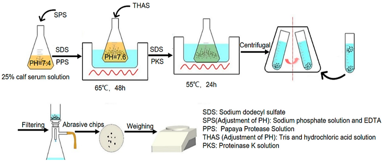
Sufficiently dried CoCrMo, UHMWPE, PEEK, and ZrO2 powders were taken in amounts of 10 mg each and their mass recorded as m before the extraction of wear debris; they were mixed thoroughly according to the combination of CoCrMo/UHMWPE, PEEK/UHMWPE, and ZrO2/UHMWPE and incubated with 10 mL of 25% calf serum solution at room temperature for 24 h.
(2)
Protein was degraded using 25 g/L sodium dodecyl sulfate, 1 g/L papain solution, and proteinase K solution diluted to 20 mg/mL with Tris-HCl solution (pH 7.6). During degradation, the pH was adjusted with sodium phosphate solution (40.99 g/L), EDTA solution (7.306 g/L), Tris (6.057 g/L), and hydrochloric acid solution. The resulting final solution was dispensed in 50 mL centrifuge tubes. The detailed degradation process was shown in Figure 3.
(3)
Centrifugation was performed at 10,000 r/min for 2 h using a high-speed centrifuge (MG15, Shanghai Maigao Scientific Instruments Co., Ltd., Shanghai, China).
(4)
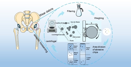
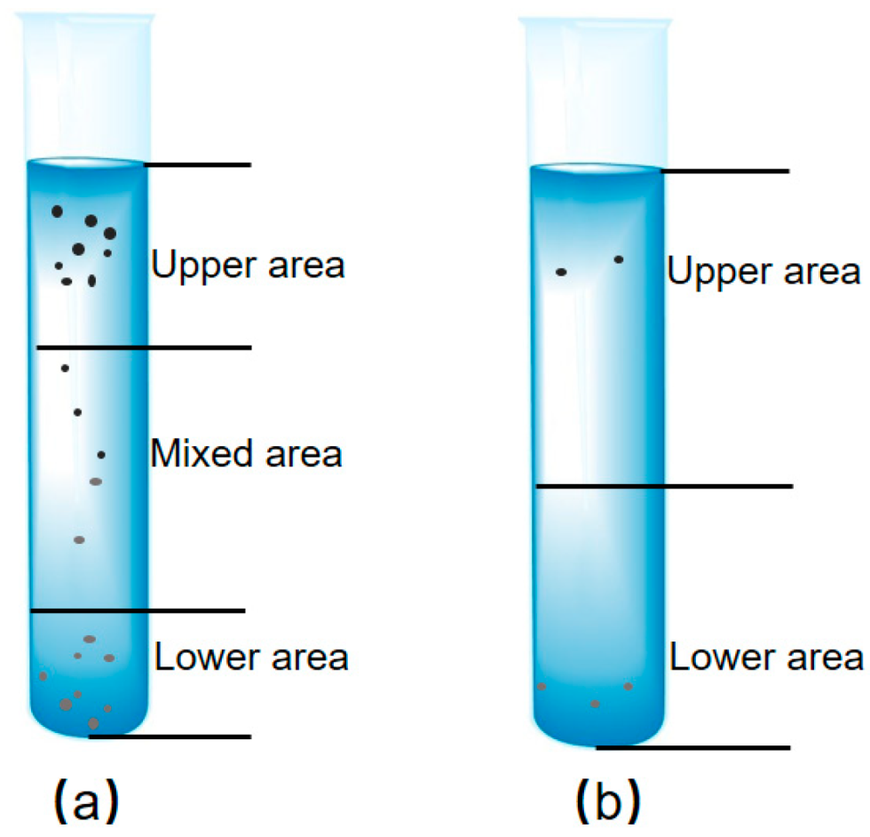
The solution in the centrifuge tubes after centrifugation was divided into an upper zone (solution containing a small density of wear debris), a mixed zone (incompletely separated mixed solution), and a lower zone (solution containing a large density of wear debris) in that order. The upper and lower zone solutions were filtered, and the mixed zone solution was moved into a new centrifuge tube. After theoretical calculations and experiments, it was proven that the three zones were divided differently for different density ratios of artificial joint mixed wear debris, and the division results are shown in Table 4 and Figure 4a.
(5)
The extracted solution of the upper zone and the solution of the lower zone were filtered through a nylon filter membrane with a pore size of 0.05 μm, and the mass of the dried filter paper with wear debris was recorded as m1. The filter paper containing the wear debris was placed in a beaker with an appropriate amount of ethanol and shaken in an ultrasonic cleaner for 20 min. The weight of the dried filter paper with wear debris was recorded as m2. The mass of the extracted wear debris was m1–m2. The ethanol suspension containing the wear debris was dried until the ethanol evaporated completely, and the composition of the remaining wear debris was analyzed.
(6)
We rinsed the wall of the original centrifuge tube with deionized water, transferred the rinsed liquid into a new centrifuge tube of mixed zone solution, and diluted the mixed zone solution with deionized water to 2/3 of the centrifuge tube.
(7)
Then, we repeated steps 3–6 for secondary and tertiary centrifugal separation and extraction. After three centrifugal separations and extractions, the operation of step 6 and 3 was repeated in turn for the fourth centrifugal separation and extraction. The solution in the centrifuge tubes after centrifugation was divided into two zones: the upper zone (solution containing small-density wear debris) and the lower zone (solution containing large-density wear debris) in turn. It was proven that the two zones were divided differently for different density ratios of artificial joint wear debris, and the results of the division are shown in Table 5 and Figure 4b. The extraction rate results after four centrifugations were calculated until it was not possible to measure the amount of extracted particles by weighing.

2.5. Wear Debris Extraction Rate

The wear debris extraction rate was used to quantify the extraction effect of wear debris under different extraction conditions. The wear debris extraction rate refers to the number of wear debris at the end of extraction as a percentage of the total wear debris before extraction and is calculated by the following formula.
R R = ( m 1 m 2 ) m × 100 %  
m, m1, and m2 are the mass of wear debris added before extraction, the total mass of filter paper and wear debris after centrifugal separation of wear debris for extraction, and the net mass of filter paper after removal of wear debris for drying, respectively.

2.6. Wear Debris Composition Analysis

To ensure that the mixed wear debris was completely separated from the rest of the calf serum and that no impurities were incorporated, compositional analysis of the post-extraction wear debris was performed. The consistency of the composition of the post-extraction wear debris with that of the wear debris added before the experiment was judged. Determination of the composition of CoCrMo wear debris after extraction from the lower zone of the CoCrMo/UHMWPE group by X-ray energy spectrometer (XflashFQ5060, Bruker, Shanghai, China). The composition of ZrO2 particles in the ZrO2/UHMWPE group was determined using X-ray energy spectrometry, and the abrasive chips were observed with a field emission transmission electron microscope (TEM) (SU8220, Hitachi, Ltd., Beijing, China). The composition of PEEK and other groups of UHMWPE particles in the PEEK/UHMWPE group was determined by infrared spectroscopy.

3. Results

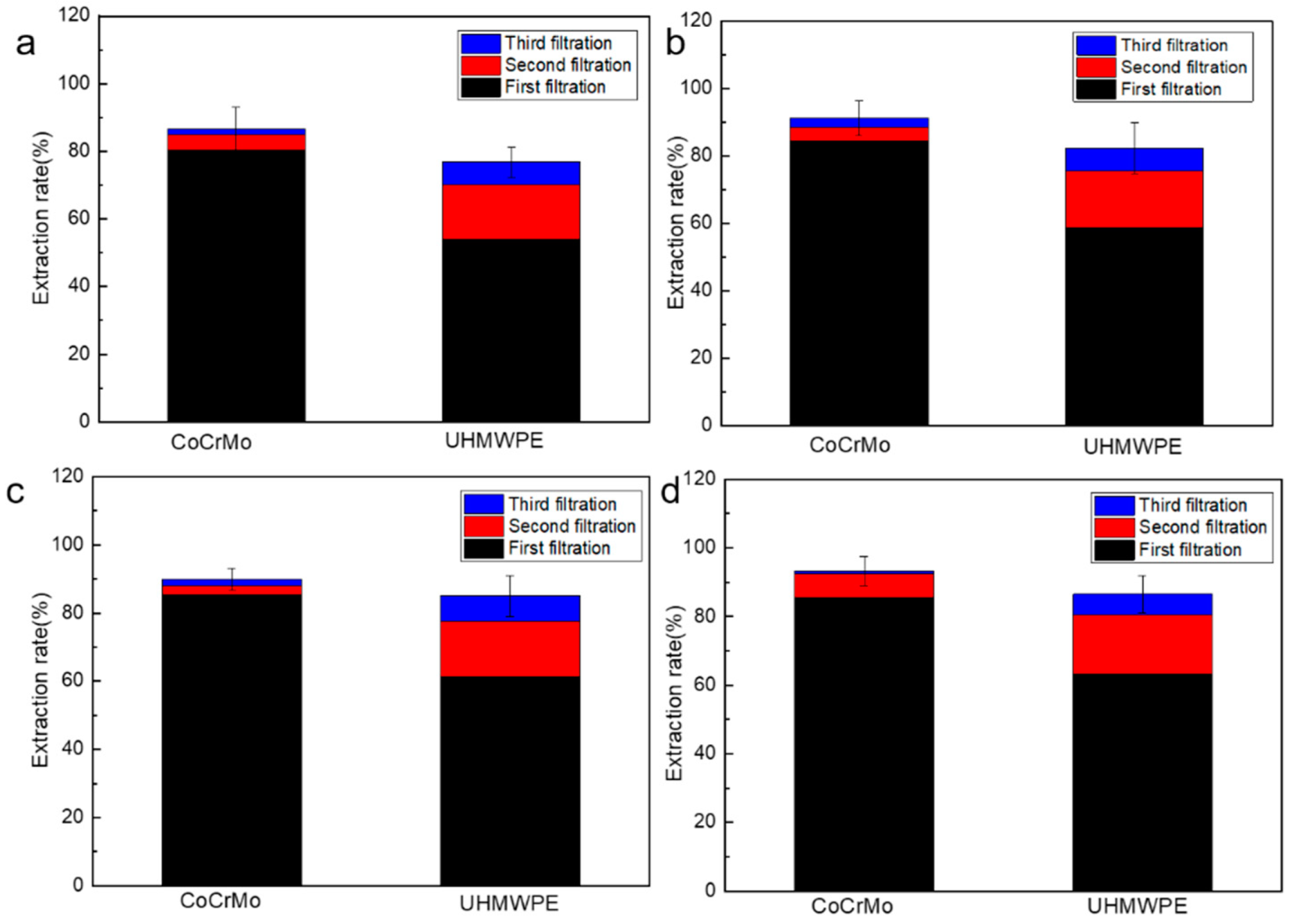
3.1. Effect of Different Centrifugation Time and Isolation Times on Recovery Rate of Mixed Wear Debris in CoCrMo/UHMWPE Group

The fourth separation of CoCrMo and UHMWPE extracted too few pieces of wear debris, all of which could not be weighed. Therefore, the first three centrifugal separations and extractions were taken into account. When the centrifugation time was 1 h, 2 h, 3 h, and 4 h, the first extraction rate of CoCrMo wear debris was 80.31%, 84.49%, 85.38%, and 85.46%, respectively. The extraction rate of wear debris increased by 4.18% more when centrifuged for two hours than when centrifuged for 1 h, and wear debris extraction rate increased by 0.89% and 0.97% more when centrifuged for 3 h and 4 h than when centrifuged for 2 h, respectively. The centrifugation was less than 2 h, and the extraction rate of CoCrMo wear debris was affected by the centrifugation time. The increase in extraction rate for CoCrMo wear debris was smaller as the centrifugation time increased. The first extraction rate of UHMWPE wear debris was 53.92%, 58.86%, 61.32%, and 63.20% when the centrifugation time was 1 h, 2 h, 3 h, and 4 h, respectively. The extraction rate of UHMWPE wear debris increased by 4.94% when the centrifugation time was 2 h compared with 1 h and increased by 2.46% and 4.34% when centrifugation was 3 h and 4 h compared with 2 h, respectively. When the centrifugation time was less than 2 h, the extraction rate of UHMWPE wear debris increased faster with the increase of centrifugation time. However, the extraction rate of UHMWPE wear debris did not increase significantly as the centrifugation time continued to rise. Centrifuged for 2 h, the second and third centrifugal separation extraction of CoCrMo wear debris increased the extraction rate by 3.9% and 6.34%, respectively, compared with the first centrifugal separation extraction. We reached a high level of extraction of CoCrMo wear debris by centrifugal separation. However, increases in centrifugal separation extraction resulted in wear debris extraction rates decreasing to below 4%. This indicates that even after increasing the number of centrifugal separations, growth in CoCrMo wear debris extraction rates was not evident. The extraction rates of UHMWPE wear debris were 58.86%, 16.79%, and 6.64%, respectively. With the increase of centrifugal separation extraction times, the extraction rate of UHMWPE wear debris gradually decreased, and the total extraction rate increased by 23.43% compared with the first extraction, so the extraction rate of UHMWPE wear debris could be significantly improved by increasing the number of centrifugal separation extraction times. The recovery rates of CoCrMo/UHMWPE mixed wear debris under different centrifugation methods are shown in Figure 5.

3.2. Effect of Different Centrifugation Time and Isolation Times on Recovery Rate of Mixed Wear Debris in PEEK/UHMWPE Group

The fourth separation of PEEK and UHMWPE extracted too little wear debris, and both could not be weighed, so the results of the first three centrifugal separations and extraction were taken. The first extraction rates of PEEK wear debris were 77.21%, 82.00%, 82.95%, and 85.18% for centrifugation times of 1 h, 2 h, 3 h, and 4 h, respectively. The extraction rates of wear debris increased by 4.79%, 5.74%, and 7.97% for centrifugation times of 2 h, 3 h, and 4 h compared to 1 h, respectively. The extraction rate of PEEK wear debris was less influenced by the centrifugation time, and the first extraction rate grew slowly by continuing to increase the centrifugation time. The first extraction rates of UHMWPE wear debris were 38.58%, 73.71%, 75.59%, and 78.89% for centrifugation times of 1 h, 2 h, 3 h, and 4 h, respectively. The extraction rate of UHMWPE wear debris increased by 35.13% for centrifugation time of 2 h compared to centrifugation for 1 h. The extraction rate of UHMWPE wear debris increased by 1.88% and 5.18% compared to 2 h when the centrifugation time was 3 h and 4 h, respectively. Comparing the results of multiple centrifugation separations, the total extraction rate of PEEK wear debris reached 88.08%, and UHMWPE wear debris reached 85.13% after three extractions at a centrifugation time of 2 h. The extraction rates of PEEK and UHMWPE wear debris decreases as the number of centrifugal separations increases, and the single extraction rate of UHMWPE is a larger percentage of the total extraction rate than that of PEEK. In summary, increasing the number of centrifugal separations can increase the extraction rate of both PEEK and UHMWPE wear debris, and the total extraction rate of UHMWPE wear chips increased more significantly. The recoveries of PEEK/UHMWPE mixed wear debris at different centrifugation times are shown in Figure 6.

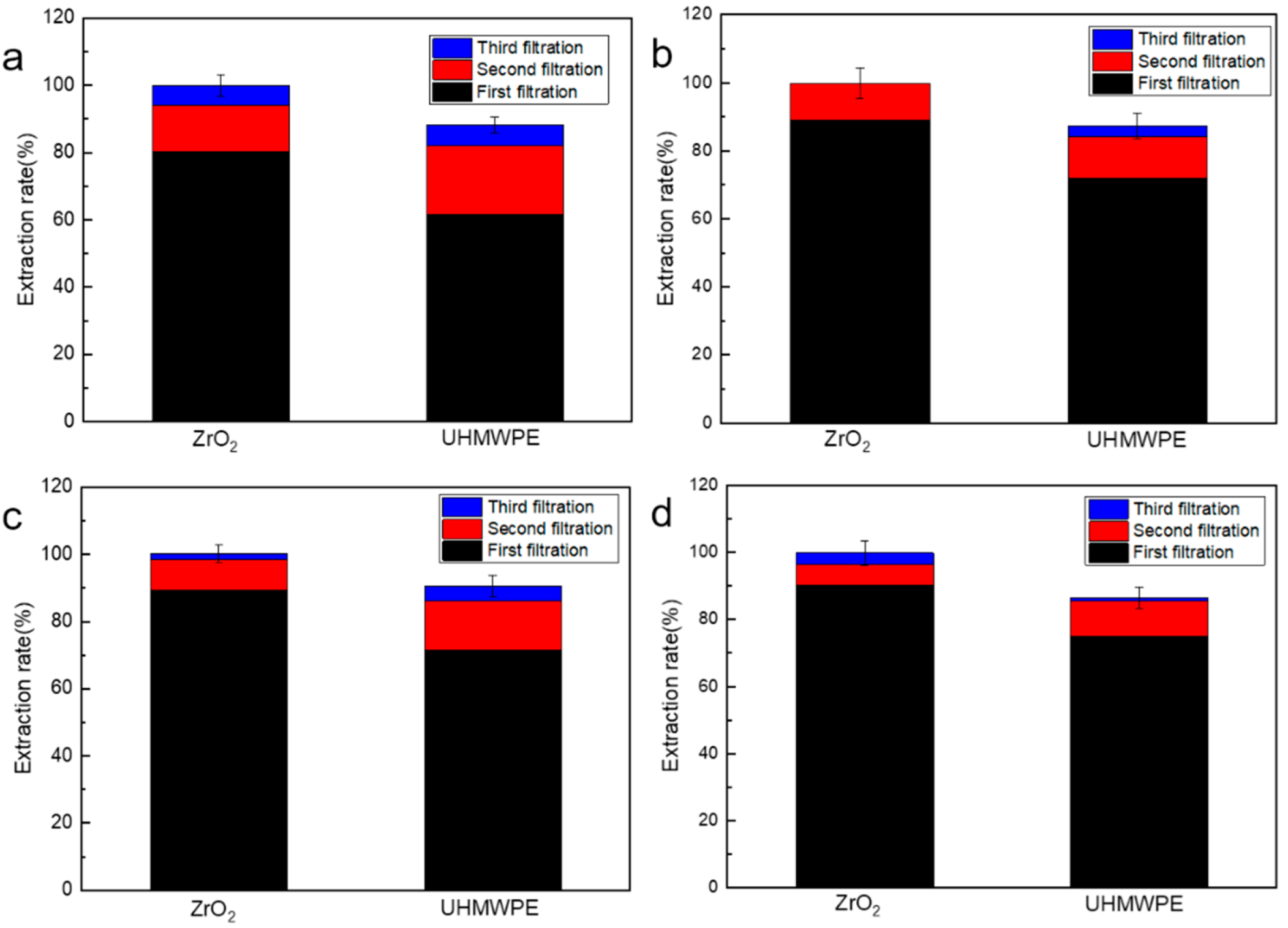
3.3. Effect of Different Centrifugation Time and Isolation Times on Recovery Rate of Mixed Wear Debris in ZrO2/UHMWPE Group

In the fourth separation of ZrO2 and UHMWPE, so little wear debris were extracted that it was impossible to weigh them, so the results of the first three centrifugal separations and extractions were used. The extraction rates of ZrO2 wear debris were 80.41%, 88.93%, 89.24%, and 90.20% for centrifugation times of 1 h, 2 h, 3 h, and 4 h, respectively. In a centrifugation time of 2 h, the extraction rate of ZrO2 wear debris increased by 8.52% compared to 1 h. The extraction rate of ZrO2 wear debris no longer increased significantly with the increase of centrifugation time when the centrifugation time was greater than 2 h. The extraction yield of UHMWPE wear debris was 61.59%, 72.01%, 72.50%, and 74.82% for centrifugation times of 1 h, 2 h, 3 h, and 4 h, respectively. Abstraction rate of UHMWPE wear debris increased by 10.42% for centrifugation time of 2 h compared with centrifugation of 1 h, and the extraction rate of wear debris increased by 0.49% and 2.81% for centrifugation of 3 h and 4 h compared with centrifugation of 2 h. Continued increase of centrifugal time has less effect on the extraction rate of UHMWPE wear debris. The extraction rate of both types of wear debris increased significantly with multiple centrifugations. As shown above, increasing the number of centrifugation extraction times can significantly improve the extraction rates of ZrO2 and UHMWPE wear debris. The recoveries of ZrO2/UHMWPE mixed wear debris under different centrifugation methods are shown in Figure 7.

3.4. Component Identification of Wear Debris Isolated

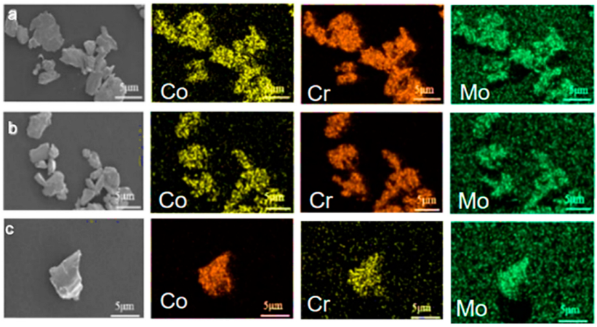
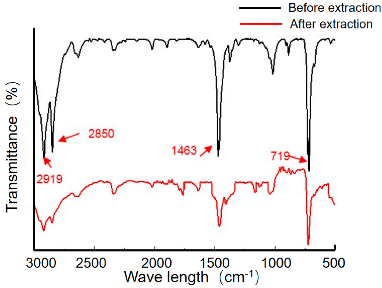
3.4.1. Analysis of the Composition of CoCrMo/UHMWPE Mixed Wear Debris after Extraction

The results of energy spectrum analysis showed that Co, Cr, and Mo elements were only detected in the region containing CoCrMo wear debris. It could be determined that the extracted wear debris were CoCrMo, and no protein contamination or UHMWPE was found. The results are shown in Figure 8.
The FT-IR result (Figure 9) showed that the absorption curves of solution-extracted UHMWPE wear debris in the upper zone were consistent with those of UHMWPE wear debris before extraction. Absorption peaks were at 2919 cm−1 (-CH2-, asymmetric stretching vibration), 2850 cm−1 (-CH2-, symmetric stretching vibration), 1463 cm−1 (-CH2-, bending vibration), and 719 cm−1 (-(CH2)-n-, n ≥ 4 in-plane rocking vibration).

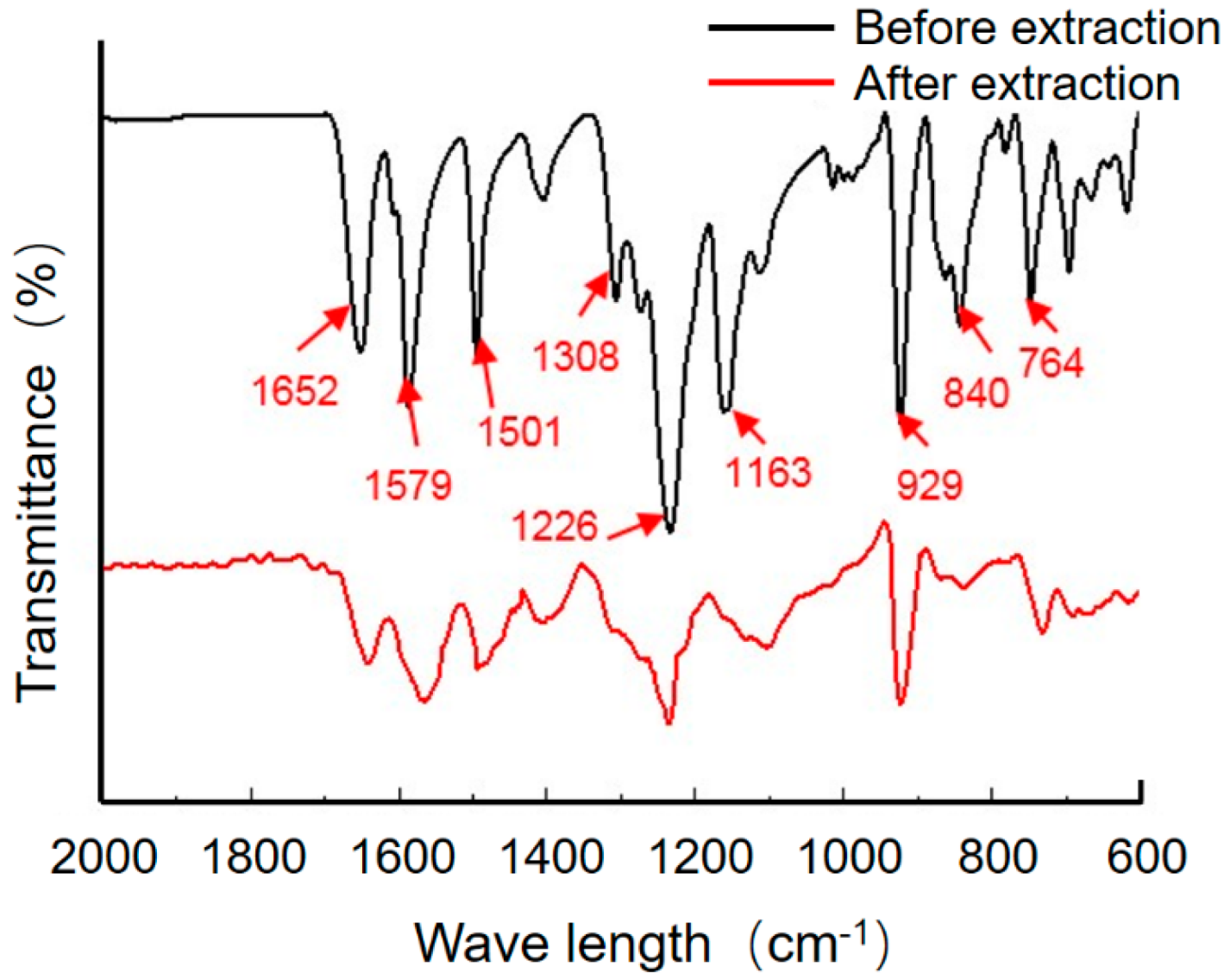
3.4.2. Post-Extraction Composition Analysis of Mixed Wear Debris of PEEK/UHMWPE Group

The FT-IR result (Figure 10) shown that the infrared absorption curves of PEEK wear debris after extraction and before extraction were consistent. Absorption peaks at 1652 cm−1 (C=O stretching vibration), 1501 cm−1, 1579 cm−1 (in-plane vibration of benzene ring), 1226 cm−1 (R-O-R asymmetric stretching vibration), 1163 cm−1 (in-plane C-H bending vibration of aromatic ether or aromatic ketone benzene ring), 840 cm−1, 764 cm−1 (out-of-plane C-H bending vibration of benzene ring). bending vibration), 840 cm−1, and 764 cm−1 (C-H out-of-plane bending vibration of benzene ring) appeared, which could indicate that the composition of the wear debris before and after extraction was PEEK. There was no admixture of UHMWPE wear debris or protein particles. The FT-IR result (Figure 11) showed the infrared spectral absorption curves of UHMWPE wear debris obtained from the upper zone solution extraction were the same as before extraction. The positions of the absorption peaks of the UHMWPE wear debris extracted from the upper zone solution and before extraction are the same, indicating that the wear debris extracted from the upper zone solution are UHMWPE. The PEEK wear debris and protein wear debris as well as other impurities are not mixed in the extraction process.

3.4.3. Analysis of Wear Debris Composition after Extraction in ZrO2/UHMWPE Group

EDS analysis (Figure 12) of solution-extracted wear debris from the lower zone of ZrO2/UHMWPE showed that ZrO2 wear debris agglomerated and formed large particle clusters. Zr and O elements occur around particle clusters and also sporadically in the area outside the particle clusters. It can be determined that the extracted wear debris are ZrO2 wear debris and occur as large particle clusters, small particle clusters, or individual particles. FT-IR (Figure 13) showed that the material structure of the extracted wear debris in the upper zone solution was the same as before extraction, indicating that the extracted wear debris in the upper zone were UHMWPE. The extracted wear debris were not mixed with ZrO2 or other impurities.

4. Discussion

In the natural state, the particle settling velocity is closely related to the particle density, radius, shape, and solvent viscosity, where the density and radius have a substantial impact [36]. In this study, high-speed centrifugation at 10,000 r/min was used to accelerate the floating or sinking of different densities of wear debris. To achieve complete separation of two different densities of artificially jointed mixed wear debris. Under centrifugal settling conditions, the disturbance flow around the wear debris is dominated by laminar and transitional types. The particles in solution are dispersed by van der Waals forces, electrostatic repulsion, capillary forces, and other interactions of particles combined with each other into clusters of particles of different diameters and dispersion. As shown by the Stokes formula, the particle stabilization phase settling velocity is proportional to the square of the particle diameter, and particle clusters rather than a single particle settling velocity increases significantly. This type of settlement is called “group sedimentation” (Figure 14a). Group sedimentation can accelerate particle sedimentation and facilitate the separation and extraction of particles of different densities in solution.
Under the wetting condition of the centrifuge tube wall, capillary forces were formed between the micro-particles and the centrifuge tube wall. The capillary forces are mainly due to the irregular surface morphology of the micro-particles. the presence of many micro-spaces or micro-gaps between the micro-particles or micro-particle clusters and the centrifuge tube surface. The capillary liquid bridge force between the particle hydrate and the centrifuge tube wall is the main adhesion force; the force is proportional to the particle radius (Figure 14b). The removal moment applied to the hydrate particles is less than the capillary liquid bridge force, and the hydrate particles adhere to the tube wall. When the removal forces on the hydrate particles were greater than the capillary bridge force, the particles leave the tube wall [37,38,39]. When the external force on the particle is greater than the static friction of the particle, the removal moment MR of the hydrate particle is greater than the impedance moment Mr, and the particle can be removed by rolling. The surface of the centrifuge tubes wall is rinsed with deionized water, in which the force of the water flow is greater than the force of the micro-particles adhering to the tube wall, and the micro-particles roll with the water flow on the surface of the centrifuge tube and finally leave the surface of the tube with the water flow. Therefore, extraction by multiple centrifugation can rinse the particles attached to the wall of the centrifuge tube after the last filtration into the solution for another centrifugation, which in turn collects more particles and achieves a higher extraction rate. The extraction rate growth of PEEK and UHMWPE wear debris was significantly higher than that of CoCrMo and ZrO2 ceramic wear debris using multiple centrifugal extraction separation extraction methods.

5. Conclusions

In this study, an extraction method of multiple centrifugal separations of different density ratios of artificial joint mixed wear debris were proposed, and the optimal centrifugal time and number of centrifugal separations were determined.
By increasing the centrifugation time to improve the extraction rate of wear debris, the increase in extraction rate of wear debris by centrifugation for 2 h versus centrifugation for 1 h is as follows: The extraction rate of CoCrMo and UHMWPE wear debris respectively increased by 47.19% and 4.94% in the CoCrMo/UHMWPE group. The extraction rate of PEEK and UHMWPE wear debris increased by 4.76% and 35.13% in PEEK/UHMPEP group. The extraction rate of ZrO2 wear debris increased by 8.52%, and UHMWPE increased by 10.42% in ZrO2/UHMWPE group. It was first proposed to increase the extraction rate of grinding chips by increasing the number of centrifugal separation extractions. After four centrifugal extractions with a centrifugal time of 2 h, the extraction rates of CoCrMo and UHMWPE wear debris in the CoCrMo/UHMWPE group reached 84.49% and 82.29%. The total extraction rates increased by 6.7% and 23.44%, respectively, compared with single centrifugal extraction. The extraction rates of PEEK and UHMWPE wear debris in the PEEK/UHMWPE group increased by 9.95% and 15.1%, respectively, compared with single centrifugal extraction. The extraction rates of ZrO2 and UHMWPE wear debris in ZrO2/UHMWPE group increased by 10.91% and 15.32%, respectively, compared with single centrifugal extraction. The multiple centrifugal separation and extraction effectively collected the abrasive debris from the wall of the centrifuge tube, and the abrasive debris extraction rate reached a relatively high level.
The research results of this paper are of great significance to the analysis of artificial knee joint materials and artificial knee joint wear characteristics, generation mechanism, and wear mechanism. It has important reference value for the prediction of the artificial knee joint life and prolongation of the artificial knee joint life and provides theoretical reference for the development and promotion of new artificial joints.

Author Contributions

Conceptualization, C.F. and T.Z.; methodology, Y.Z.; software, T.Z.; validation, C.F., Y.Z.; formal analysis, C.F. and Y.Z.; investigation, C.F., and Y.Z.; resources, T.Z.; data curation, C.F., Y.Z.; writing—original draft preparation, Y.Z.; writing—review and editing, C.F.; visualization, C.F. and Y.Z.; supervision, D.Z.; project administration, K.C., X.L. and D.Z. All authors have read and agreed to the published version of the manuscript.

Funding

This study was supported by the National Natural Science Foundation of China (No. 51875564, 52105231 and 52175204), Natural Science Foundation of Jiangsu Province (Grant No. BK20211243), the Fundamental Research Funds for the Central Universities (2021QN1108), the Tribology Science Fund of State Key Laboratory of Tribology (Grant No. SKLTKF21B15), and the Open Fund of State Key Laboratory of Solid Lubrication, Lanzhou Institute of Chemical Physics (Grant No. LSL-2107).

Data Availability Statement

Not applicable.

Conflicts of Interest

The authors who have taken part in this study declared that they do not have anything to disclose regarding funding or conflict of interest with respect to this manuscript.

References

  1. Yoneyama, C.; Cao, S.; Munoz, A.I.; Mischler, S. Influence of Bovine Serum Albumin (BSA) on the Tribocorrosion Behaviour of a Low Carbon CoCrMo Alloy in Simulated Body Fluids. Lubricants 2020, 8, 61. [Google Scholar] [CrossRef]
  2. DeLee, J.G.; Charnley, J. Radiological demarcation of cemented sockets in total hip replacement. Clin. Orthop. Relat. Res. 1976, 121, 20–32. [Google Scholar] [CrossRef]
  3. Chiesa, R.; Tanzi, M.; Alfonsi, S.; Paracchini, L.; Moscatelli, M.; Cigada, A. Enhanced wear performance of highly crosslinked UHMWPE for artificial joints. J. Biomed. Mater. Res. 2000, 50, 381–387. [Google Scholar] [CrossRef]
  4. Kyomoto, M.; Moro, T.; Takatori, Y.; Tanaka, S.; Ishihara, K. Multidirectional Wear and Impact-to-wear Tests of Phospholipid-polymer-grafted and Vitamin E-blended Crosslinked Polyethylene: A Pilot Study. Clin. Orthop. Relat. Res. 2015, 473, 942–951. [Google Scholar] [CrossRef] [PubMed]
  5. Moro, T.; Takatori, Y.; Kyomoto, M.; Ishihara, K.; Kawaguchi, H.; Hashimoto, M.; Tanaka, T.; Oshima, H.; Tanaka, S. Wear resistance of the biocompatible phospholipid polymer-grafted highly cross-linked polyethylene liner against larger femoral head. J. Orthop. Res. 2015, 33, 1103–1110. [Google Scholar] [CrossRef]
  6. Hongtao, L.; Shirong, G.; Shoufan, C.; Shibo, W. Comparison of wear debris generated from ultra high molecular weight polyethylene in vivo and in artificial joint simulator. Wear 2011, 271, 647–652. [Google Scholar] [CrossRef]
  7. Minoda, Y.; Kobayashi, A.; Iwaki, H.; Miyaguchi, M.; Kadoya, Y.; Ohashi, H.; Takaoka, K. Characteristics of polyethylene wear particles isolated from synovial fluid after mobile-bearing and posterior-stabilized total knee arthroplasties. J. Biomed. Mater. Res. B 2004, 71, 1–6. [Google Scholar] [CrossRef]
  8. McMullin, B.; Leung, M.; Shanbhag, A.; McNulty, D.; Mabrey, J.; Agrawal, C. Correlating subjective and objective descriptors of ultra high molecular weight wear particles from total joint prostheses. Biomaterials 2006, 27, 752–757. [Google Scholar] [CrossRef]
  9. Matthews, J.B.; Besong, A.A.; Green, T.R.; Stone, M.H.; Wroblewski, B.M.; Fisher, J.; Ingham, E. Evaluation of the response of primary human peripheral blood mononuclear phagocytes to challenge with In vitro generated clinically relevant UHMWPE particles of known size and dose. J. Biomed. Mater. Res. 2000, 52, 296–307. [Google Scholar] [CrossRef]
  10. Halim, T.; Clarke, I.C.; Burgett-Moreno, M.D.; Donaldson, T.K.; Savisaar, C.; Bowsher, J.G. A simulator study of adverse wear with metal and cement debris contamination in metal-on-metal hip bearings. Bone Jt. Res. 2015, 4, 29–37. [Google Scholar] [CrossRef]
  11. Halim, T.; Burgett, M.; Donaldson, T.K.; Savisaar, C.; Bowsher, J.; Clarke, I.C. Profiling the third-body wear damage produced in CoCr surfaces by bone cement, CoCr, and Ti6Al4V debris: A 10-cycle metal-on-metal simulator test. Proc. Inst. Mech. Eng. Part H 2014, 228, 703–713. [Google Scholar] [CrossRef] [PubMed]
  12. Brown, C.; Williams, S.; Tipper, J.L.; Fisher, J.; Ingham, E. Characterisation of wear particles produced by metal on metal and ceramic on metal hip prostheses under standard and microseparation simulation. J. Mater. Sci. Mater. Med. 2007, 18, 819–827. [Google Scholar] [CrossRef] [PubMed]
  13. Milosev, I.; Remskar, M. In vivo production of nanosized metal wear debris formed by tribochemical reaction as confirmed by high-resolution TEM and XPS analyses. J. Biomed. Mater. Res. Part A 2009, 91, 1100–1110. [Google Scholar] [CrossRef] [PubMed]
  14. McKee, G.K.; Watson-Farrar, J. Replacement of arthritic hips by the McKee-Farrar prosthesis. J. Bone Jt. Surg. 1966, 48, 245–259. [Google Scholar] [CrossRef]
  15. Tuan, R.S.; Lee, F.Y.; Konttinen, Y.T.; Wilkinson, J.M.; Smith, R.L. What are the local and systemic biologic reactions and mediators to wear debris, and what host factors determine or modulate the biologic response to wear particles? J. Am. Acad. Orthop. Surg. 2008, 16, S42–S48. [Google Scholar] [CrossRef]
  16. Ingham, E.; Fisher, J. The role of macrophages in osteolysis of total joint replacement. Biomaterials 2005, 26, 1271–1286. [Google Scholar] [CrossRef]
  17. Bitar, D.; Parvizi, J. Biological response to prosthetic debris. World, J. Orthop. 2015, 6, 172–189. [Google Scholar] [CrossRef]
  18. Huang, C.; Lu, Y.; Chang, T.; Hsiao, I.; Su, Y.; Yeh, S.; Fang, H.; Huang, C. In vivo biological response to highly cross-linked and vitamin e-doped polyethylenea particle-Induced osteolysis animal study. J. Biomed. Mater. Res. Part B 2016, 104, 561–567. [Google Scholar] [CrossRef]
  19. Ingham, E.; Fisher, J. Biological reactions to wear debris in total joint replacement. Proc. Inst. Mech. Eng. Part H 2000, 214, 21–37. [Google Scholar] [CrossRef]
  20. Affatato, S.; Bersaglia, G.; Rocchi, M.; Taddei, P.; Fagnano, C.; Toni, A. Wear behaviour of cross-linked polyethylene assessed in vitro under severe conditions. Biomaterials 2005, 26, 3259–3267. [Google Scholar] [CrossRef]
  21. Smith, A.M.; Fleming, L.; Wudebwe, U.; Bowen, J.; Grover, L.M. Development of a synovial fluid analogue with bio-relevant rheology for wear testing of orthopaedic implants. J. Mech. Behav. Biomed. Mater. 2014, 32, 177–184. [Google Scholar] [CrossRef] [PubMed]
  22. Ghosh, S.; Choudhury, D.; Roy, T.; Moradi, A.; Masjuki, H.H.; Pingguan-Murphy, B. Tribological performance of the biological components of synovial fluid in artificial joint implants. Sci. Technol. Adv. Mater. 2015, 16, 045002. [Google Scholar] [CrossRef] [PubMed]
  23. Visentin, M.; Stea, S.; Squarzoni, S.; Antonietti, B.; Reggiani, M.; Toni, A. A new method for isolation of polyethylene wear debris from tissue and synovial fluid. Biomaterials 2004, 25, 5531–5537. [Google Scholar] [CrossRef]
  24. Singh, J.; Sloan, J.A.; Johanson, N.A. Challenges with Health-related Quality of Life Assessment in Arthroplasty Patients: Problems and Solutions. J. Am. Acad. Orthop. Surg. 2010, 18, 72–82. [Google Scholar] [CrossRef]
  25. Kurtz, S.M.; Austin, M.S.; Azzam, K.; Sharkey, P.F.; MacDonald, D.W.; Medel, F.J.; Hozack, W.J. Mechanical Properties, Oxidation, and Clinical Performance of Retrieved Highly Cross-Linked Crossfire Liners After Intermediate-Term Implantation. J. Arthroplast. 2010, 25, 614–623. [Google Scholar] [CrossRef]
  26. Park, D.Y.; Min, B.H.; Kim, D.W.; Song, B.R.; Kim, M.; Kim, Y.J. Polyethylene wear particles play a role in development of osteoarthritis via detrimental effects on cartilage, meniscus, and synovium. Osteoarthr. Cartil. 2013, 21, 2021–2029. [Google Scholar] [CrossRef] [PubMed]
  27. Pourzal, R.; Catelas, I.; Theissmann, R.; Kaddick, C.; Fischer, A. Characterization of wear particles generated from CoCrMo alloy under sliding wear conditions. Wear 2011, 271, 1658–1666. [Google Scholar] [CrossRef]
  28. Gajski, G.; Jelcic, Z.; Orescanin, V.; Geric, M.; Kollar, R.; Garaj-Vrhovac, V. Physico-chemical characterization and the in vitro genotoxicity of medical implants metal alloy (TiAlV and CoCrMo) and polyethylene particles in human lymphocytes. BBA-Gen. Subj. 2014, 1840, 565–576. [Google Scholar] [CrossRef]
  29. Anand, L. Plane deformations of ideal granular materials. J. Mech. Phys. Solids 1983, 31, 105–122. [Google Scholar] [CrossRef]
  30. Cheng, N. Comparison of formulas for drag coefficient and settling velocity of spherical particles. Powder Technol. 2009, 189, 395–398. [Google Scholar] [CrossRef]
  31. Markauskas, D.; Kruggel-Emden, H.; Sivanesapillai, R.; Steeb, H. Comparative study on mesh-based and mesh-less coupled CFD-DEM methods to model particle-laden flow. Powder Technol. 2017, 305, 78–88. [Google Scholar] [CrossRef]
  32. Fan, L. Multiphase flow and fluidization: Continuum and kinetic theory descriptions. AIChE J. 1996, 42, 1197–1198. [Google Scholar] [CrossRef]
  33. Jenny, M.; Souhar, M. Numerical simulation of a film coating flow at low capillary numbers. Comput. Fluids 2009, 38, 1823–1832. [Google Scholar] [CrossRef]
  34. Leung, W. Separation of dispersed suspension in rotating test tube. Sep. Purif. Technol. 2004, 38, 99–119. [Google Scholar] [CrossRef]
  35. Richardson, J.F.; Zaki, W.N. The sedimentation of a suspension of uniform spheres under conditions of viscous flow. Chem. Eng. Sci. 1954, 3, 65–73. [Google Scholar] [CrossRef]
  36. Larsen, T. Measuring the variations of the apparent settling velocity for fine particles. Water Res. 2000, 34, 1417–1418. [Google Scholar] [CrossRef]
  37. Sanchez-Reyes, J.; Archer, L. Interfacial slip violations in polymer solutions: Role of microscale surface roughness. Langmuir 2003, 19, 3304–3312. [Google Scholar] [CrossRef]
  38. Wang, S.; Drda, P.A. Superfluid-Like Stick−Slip Transition in Capillary Flow of Linear Polyethylene Melts. 1. General Features. Macromolecules 1996, 29, 2627–2632. [Google Scholar] [CrossRef]
  39. Brochard, F.; De Gennes, P.G. Shear-dependent slippage at a polymer/solid interface. Langmuir 1992, 8, 3033–3037. [Google Scholar] [CrossRef]
Figure 1. Principle picture of separation system of VN-2 micro-nano particle isolation device.
Lubricants 10 00226 g001
Figure 2. Schematic diagram and photograph of VN-2 micro-nano-particle isolation device.
Lubricants 10 00226 g002
Figure 3. Flow diagram of wear debris separation by multi-centrifugation.
Lubricants 10 00226 g003
Figure 4. (a) Schematic diagram of solution isolation area after the first three centrifugations; (b) schematic diagram of solution extraction area after four or more centrifugations.
Lubricants 10 00226 g004
Figure 5. Recovery rate of CoCrMo/UHMWPE mixed particles with different centrifugation time and isolation times: (a) 1 h, (b) 2 h, (c) 3 h, and (d) 4 h.
Lubricants 10 00226 g005
Figure 6. Recovery rate of PEEK/UHMWPE mixed particles with different centrifugation time and isolation times: (a) 1 h, (b) 2 h, (c) 3 h, and (d) 4 h.
Lubricants 10 00226 g006
Figure 7. Recovery rate of ZrO2/UHMWPE mixed wear debris with different centrifugation time and isolation times: (a) 1 h, (b) 2 h, (c) 3 h, and (d) 4 h.
Lubricants 10 00226 g007
Figure 8. Elemental analysis of isolated CoCrMo wear debris: (a) first time, (b) second time, and (c) third time.
Lubricants 10 00226 g008
Figure 9. FITR spectra of isolated wear debris in upper zone of CoCrMo/UHMWPE group and non−isolated UHMWPE wear debris.
Lubricants 10 00226 g009
Figure 10. FITR spectrum of isolated wear debris in lower zone of PEEK/UHMWPE group and non−isolated PEEK wear debris.
Lubricants 10 00226 g010
Figure 11. FITR spectrum of isolated wear debris in upper zone of PEEK/UHMWPE group and non−isolated UHMWPE wear debris.
Lubricants 10 00226 g011
Figure 12. Elemental analysis of isolated ZrO2 wear debris; (a) isolated ZrO2 wear debris after first centrifugation; (b) isolated ZrO2 wear debris after second centrifugation; (c) isolated ZrO2 wear debris after third centrifugation.
Lubricants 10 00226 g012
Figure 13. FITR spectrum of isolated wear debris in upper zone of PEEK/UHMWPE group and non−isolated UHMWPE wear debris.
Lubricants 10 00226 g013
Figure 14. (a) Schematic diagram of fine particle flow in centrifugal tube; (b) schematic diagram of removal mechanism of particles attached to centrifugal tube wall.
Lubricants 10 00226 g014
Table 1. Mixed wear debris with different density of artificial joint.
Artificial Joint MaterialsDensity (g/cm3)
CoCrMo/UHMWPE8.375/0.960
PEEK/UHMWPE1.375/0.960
ZrO2/UHMWPE6.000/0.960
Table 2. Settling velocity of single spherical wear debris of different density in suspension.
Abrasive DustSedimentation Velocity × 10−5 (mm/h)
UHMWPE0.077
PEEK0.723
ZrO2975.960
CoCrMo1434.960
Table 3. Settling velocity of particles in fluid with different motion states.
Abrasive ChipsLaminar Flow Area
(mm/h)
Transition Area
(mm/h)
Turbulent Region (mm/h)
UHMWPE5.141.11111,306.65
PEEK48.455.78311,085.42
ZrO2654.7838.901,142,589.63
CoCrMo962.4851.661,385,285.83
Table 4. Solution separation zone after the first three centrifugations.
Mixed Wear DebrisUpper Area (100%)Lower Area (100%)
CoCrMo/UHMWPE35–503.75–5
PEEK/UHMWPE25–355–7.5
ZrO2/UHMWPE5–125–10
Table 5. Solution separation zone after the first three centrifugations.
Mixed Wear DebrisUpper Area (100%)Lower Area (100%)
CoCrMo/UHMWPE70–8020–30
PEEK/UHMWPE45–5545–55
ZrO2/UHMWPE60–7030–40
Publisher’s Note: MDPI stays neutral with regard to jurisdictional claims in published maps and institutional affiliations.

