Abstract
Adequately designed and positioned surface textures are recognized as a promising way to increase load-carrying capacity and reduce frictional losses of journal bearings. The aim of this work is to analyze the local lubrication mechanisms of textures in journal bearings from microflow perspective, while considering the interactions between textures and the film formation in the whole bearing. For this purpose, hydrodynamic lubrication models of textured journal bearings are built. The results show that placing textures downstream of the high-pressure region leads to a reduced friction force, with a less severe loss of load-carrying capacity. The effects of textures on the load-carrying capacity include the positive micro-hydrodynamic pressure effect and the negative effect caused by the discontinuity of the high-pressure region. The micro-hydrodynamic pressure of textures can be generated on one hand by limiting pressure drop (cavitation) in the divergent gap and on the other hand by the inertia effect. For the friction, the vortex inside textures affects the friction force by influencing the maximum shear stress at the minimum oil film. In turn the vortex is influenced by the bearing lubrication film. The research provides the fundamental reference and theoretical basis for the design and optimization of textured journal bearings.
1. Introduction
Journal bearings have attracted much attention for its widely potential applications, including various subsystems in engines and powertrains [1,2]. The growing demand for energy efficiency and sustainability requires lower friction and higher load-carrying capacity in journal bearings [3,4,5]. Surface textures have been proven to be a promising way for improving tribological behaviors of journal bearings [6,7]. Several beneficial effects have been identified experimentally and numerically, including acting as local lubricant reservoirs [8,9], entrapping wear debris [10,11], reducing contact area under direct contact of surfaces [12,13], especially reducing friction [14,15,16] as well as building up an additional micro-hydrodynamic pressure [17,18,19]. However, textures also can be detrimental if designed wrong, for example, the full texturing or distribution within the high-pressure region as reported by Dobrica et al. [20] and Fowell et al. [21]. To determine the optimal geometries and positions for textures, the lubrication mechanisms of textures in a whole journal bearing including loading enhancement and friction reduction need to be clear.
To understand the tribological performance enhancement of textures, a large number of numerical investigations have been conducted from a single texture cell during the past years [22,23,24]. For instance, the cavitation effect in a textured surface was firstly proposed by Hamilton et al. [25] and Estion et al. [23,26]. A negative pressure would generate at the entrance of textures due to the sudden increase of flow area and a positive pressure was following because of the convergence of flow area. When the cavitation occurred, the negative pressure was limited by the saturation pressure which caused an asymmetric but overall lifting pressure. Subsequently, inertia effect was proposed and investigated by Arghir et al. [27]. By solving Navier–Stokes equations, they concluded that a positive load-carrying capacity could be generated by an inertia effect, especially for the lubrication conditions with a high Reynolds number. This conclusion was also in agreement with the findings by Sahlin et al. [28] and Keller et al. [29]. Another lubrication mechanism was the entrainment and inlet suction effect suggested by Fowell et al. [30]. The negative pressure at the entrance of textures sucked more lubricant into dimples, thus enhancing the pressure build-up and load-carrying capacity of textured contacts. Besides, Tønder [31] proposed the collective effect and showed that the change of film thickness caused by textures had a similar function as a Rayleigh step bearing to create an additional load-carrying capacity. However, most of the aforementioned lectures focused on the loading mechanism, whereas the friction reduction mechanism was not the focus of these works. In addition, those studies were mainly based on a single texture element. Multiple textures and their interactions were not considered, making the results not applicable to journal bearings directly, due to the local differences in pressure and the potential perturbation of lubricant flow on the component level.
One of the initial works considering the textures’ interactions was carried out by Tala-Ighil et al. [32,33]. By solving the Reynolds equation, they found the partial texturing was more efficient to improve the tribological performance than the full texturing. Furthermore, an analysis was carried out by Brizmer and Kligerman to study the effect of surface textures on load-carrying capacity at the fixed eccentricity ratio of 0.1–0.9 [34]. They reported that the load-carrying capacity could only be improved by partial texturing at low eccentricities. Similar conclusions were also made by Kango et al. [35]. Usman et al. [36] compared the friction coefficient at the ratio of 0.6~0.9 and demonstrated that textures could effectively reduce the friction. This conclusion was experimentally confirmed by Vlădescu et al. [37] and numerically verified by Singh et al. [38].
The effects of different textured geometry and distribution on the lubrication characteristics of journal bearings have also been investigated. The friction performances for the bearings with the compound dimples and simple dimples were compared by Meng et al. at the eccentricity ratio of 0.8 [39]. Liang et al. [40] studied the effects of textured geometrical parameters and distribution on the bearing lubrication performance at the eccentricity ratio of 0.3 and showed that the beneficial effect of the micro-textures needed the reasonable combination of the textured depth and distribution. Shinde et al. [41] conducted the numerical analysis on the performance of hydrodynamic journal bearing with partial texturing at the eccentricity ratio of 0.6. They stated that the bearing lubrication performance was significantly influenced by textured position. Furthermore, as pointed out by Arif et al. [42], the textured position can significantly affect the bearing lubrication performance, and even more than textured geometry. An external load should be specified instead of a fixed eccentricity when optimizing the textured journal bearings, as recent work stated by Marian et al. [24] and Yamada et al. [43]. In contrast, as demonstrated in the aforementioned studies [34,35,36,38,39,40,41], the method with a fixed eccentricity ratio is suitable to study the flow characteristics of the textured journal bearings. However, most of the related studies focused on comparing the influence of different textured parameters on the bearing performance from the whole journal bearing, and the reasons of those influence are not analyzed from the microflow inside textures.
In addition, the microflow effects in textures and the macro-hydrodynamic lubrication film formation influence each other [44]. Therefore, both of them must be considered in one model. However, the classical Reynolds equation, which is widely used to analyze the flow field of textured journal bearings, is simplified from the Navier–Stokes equations by neglecting the inertia effect and the flow across the film gap. According to the inertia effect mentioned above, the Reynolds equation cannot predict this microflow phenomena as demanded [27,28,29]. In addition, the vortex which was neglected by the Reynolds equation was found inside textures by Sahlin et al. [28]. The vortex was indicated to be related to textured bearing performance by Wang et al. [45,46]. However, how will the vortex in textures influence the flow in bearing clearance has not been clarified. Therefore, the lubrication mechanisms of textures as well as their interaction with the lubrication film in the whole bearings need to be based on a more accurate prediction, and it should be derived from the microflow analysis inside the textures.
Consequently, the aim of this study is to analyze the lubrication mechanisms of textures in journal bearings from the microflow perspective while considering the interactions between textures and the film formation in the whole bearing. For this purpose, Computational Fluid Dynamics (CFD) models of textured journal bearings with different geometries and positions are firstly built up to investigate the macro-effect of textures on the bearing performance. Subsequently, the microflow inside textures is captured to clarify the micro lubrication mechanisms of textures. Finally, the microflow of textures under different positions of lubrication film is investigated to clarify the interactions between the microflow inside textures and the macro-hydrodynamic lubrication film.
2. Numerical Method
2.1. Governing Equations
The hydrodynamic simulation in the current work is carried out in the cavitatingFoam solver of OpenFOAM. This solver is based on a homogenous equilibrium model for cavitation, which means that the two phases liquid/vapor are supposed to be in thermodynamic equilibrium [47,48]. A barotropic equation of state is implanted in the continuity equation to produce a pressure equation. When the pressure falls below the saturation pressure, it will lead to the occurrence of cavitation.
In the present study, a steady state is assumed and the thermal effect is ignored. The lubricant is assumed as a Newtonian fluid with a constant viscosity. To solve the fluid flow, basic flow governing equations, including the continuity equation and momentum conservation equation [49], are given as follows:
where ρm represents density, is velocity vector, p is pressure, is the stress tensor (given in Equation (3)), and is the gravity force.
where is fluid viscosity, is the unit tensor, and the second term on the right-hand side is the effect of volume dilation.
In Equation (2), the first two terms in the left-hand side are the inertia terms. To analyze the inertia effect of textures, a new solver without inertial term is created as Equation (4):
The mixture density can be calculated by considering the fraction of vapor in the fluid. The mixture’s equilibrium equation of state is following:
where is the density of liquid at reference pressure, and are the compressibility of liquid and vapor, is the mass fraction of vapor in the fluid mixture, which is calculated by:
where ρm, ρl,sat and ρv,sat are density of the mixture, liquid and vapor densities at saturation pressure, respectively. There is no cavitation when = 0, whereas the fluid cell is fully occupied by vapor when = 1. Then, the mixture compressibility Ψm is obtained by the Wallis linear model [50]:
The local mixture viscosity is calculated as:
where, and are the viscosity of liquid and vapor, respectively.
The flowchart of the simulation is presented as Figure 1. For a more detailed description, the reader is referred to Ref. [49]. Firstly, the mesh model and boundary conditions are implemented. Subsequently, the fraction of oil is calculated and updated from Equation (6). Then, the transport properties, including the mixture compressibility and the mixture viscosity, are updated according to Equations (7) and (8). Next, Equations (1) and (2) are solved based on the PIMPLE Algorithm to update the pressure and velocity field while considering the inertia effect. To study the impact of inertia effect, the momentum conservation equation is modified. Equations (1) and (2) are replaced by Equations (1) and (4). In both cases, the mixture density is further updated based on Equation (5).
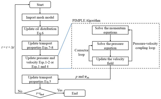
Figure 1.
Simulation flowchart.
2.2. Physical Model
The geometry of the journal bearing investigated in the present work is composed of a moving smooth wall with a constant angular velocity and a stationary textured wall, which is schematically illustrated in Figure 2. The lubricant flows into the bearing from the top side and flows out from the both sides. As stated in the introduction, the fixed eccentricity ratio is used to clarify the influence of microflow inside textures on the flow in the bearing clearance. The parameters of bearing geometry and boundary conditions used in the present study are listed in Table 1.
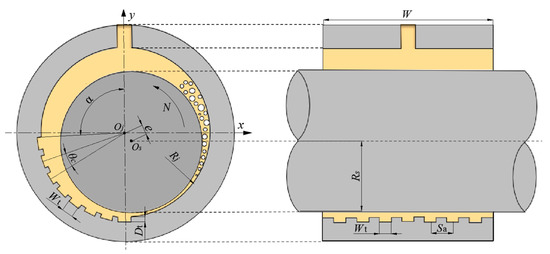
Figure 2.
Hydrodynamic journal bearing geometry. Oj means center of journal bearing, Os means center of shaft, e means eccentricity distance, N means rotational speed, Rj means bearing radius, Rs means shaft radius, Dt means textured depth, Wt means textured width, θc means textured space in circumferential direction, Sa means textured space in axial direction, α means starting angle of textured zone, W means bearing width.

Table 1.
Geometric parameters of the bearing model.
In the present work, four geometry cases are named accordingly to width and depth of textures. Five different positions are considered and defined by the starting angle of textured zone α. Each geometry is simulated under the five textured positions from 50° to 250°. All the simulation cases are listed in Table 2.
Table 2.
Parameters of simulation cases.
The mesh quality and mesh density of the model are keys to ensuring the accuracy of the calculation results. With the aim of determining the proper mesh quantity, a mesh independence study is carried out and shown in Figure 3. As a result, the division across the film thickness is 5 and the division across the textured depth is 6. The interval size used in the other directions is 2 × 10⁻⁴ m. The mesh model of the textured journal bearing is exemplarity shown in Figure 4, and the mesh parameters of the simulation model are listed in Table 3.
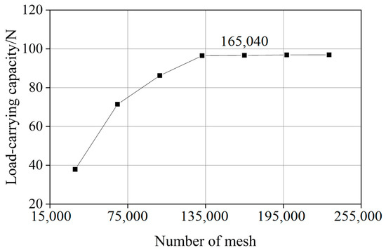
Figure 3.
Mesh independence for the simulation model.
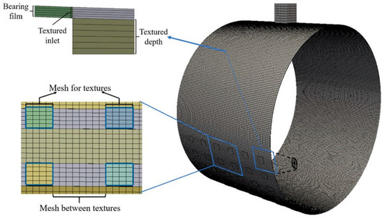
Figure 4.
CFD mesh model of the textured journal bearing.
Table 3.
Mesh parameters.
2.3. Validation
To verify the reliability of this solver, the simulation results from our model are firstly compared with that from the Reynolds equation. The forced boundary condition is used for cavitation in the calculation of Reynolds equation. The pressure is set to psat when p < psat [51]. It can be seen from Figure 5a,b that the pressure profiles calculated with the current method are in a good agreement to that from the Reynolds equation. Specifically, the differences of the maximum pressure are both within 5%, which is assumed to be related to the different cavitation models used in the two approaches and the simplifications of the Reynolds equation.
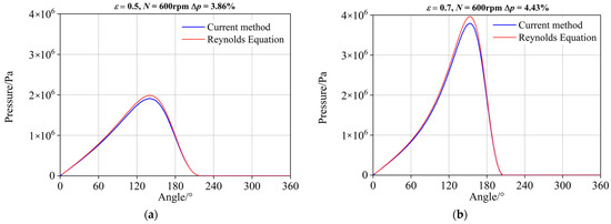
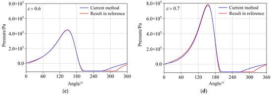
Figure 5.
Validation of the current method. (a) ε = 0.5, Reynolds equation; (b) ε = 0.7, Reynolds equation; (c) ε = 0.6, Ref. [52]; (d) ε = 0.7, Ref. [52]; Top: Validation of current method with Reynolds equation, Bottom: Validation of current method with data from Ref. [52].
In addition, the validation is carried out to compare the results with the work from Gao et al. [52], whose method was validated with the corresponding experimental data. According to Ref. [52], the pressure relative to the respective atmospheric pressure (101,325 Pa) is used for the validation. As can be seen from Figure 5c,d, the pressure profiles predicted from the current method are in a good agreement with the results from Ref. [52] at different eccentricity ratios, which also suggests the validation of the current method. The differences in the cavitation region are mainly caused by the different cavitation models. The Zwart–Gerber–Belamri model was used in Ref. [52] while a homogenous equilibrium model for cavitation is used in the present work.
3. Results and Discussion
In order to investigate the lubrication mechanisms of textures in journal bearings, multiple simulations with various textured geometries and positions were performed to analyze the effect of textures on the load-carrying capacity and friction force. Subsequently, the microflow inside textures is captured to clarify the lubrication mechanisms of textures as well as the interactions between the microflow inside textures and the macro-hydrodynamic lubrication film.
3.1. Effect of Textures on the Load-Carrying Capacity
The load-carrying capacity under different textured geometries and positions are shown in Figure 6. ΔW is the percentage difference in load-carrying capacity between smooth and textured bearings, defined as . The subscripts s and t stand for the smooth and textured bearings. It can be found that compared with the smooth bearing, the load-carrying capacity of textured bearings is reduced, especially when textures are distributed near the high-pressure region (from 160° to 210° in the present work). For the small textured width (W1D15 and W1D50), the differences between textured and smooth bearings are all within 6%. While the textured width increases to 2 mm (W2D15 and W2D50), the effect of textures is much more significant.
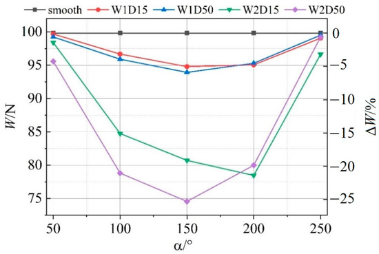
Figure 6.
Load-carrying capacity under different textured geometries and positions.
To analyze the effect of textures on the load-carrying capacity of journal bearings, the influence of textures on the pressure distribution is firstly discussed. Figure 7 shows the pressure contour of W1D50 under different textured positions. Figure 7d,e show that when the textures are distributed in the high-pressure region, the continuity of the high-pressure region is disrupted and the maximum pressure decreases. The results are in agreement with previously published work by Lin et al. [53]. When the textures are distributed outside the high-pressure region, the maximum pressure of the bearing will not be significantly affected. Especially when the textures are distributed downstream of the high-pressure region, the maximum pressure of the textured bearing even rises slightly, as shown in Figure 7f.
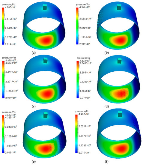
Figure 7.
Pressure contours under different textured positions. (a) smooth bearing; (b) α = 50°; (c) α = 100°; (d) α = 150°; (e) α = 200°; (f) α = 250°.
The pressure profiles at the centerline of textured journal bearings are captured and compared with that of the smooth bearing in Figure 8. It can be observed that when the lubricant flows through the textures, the pressure will drop first and then rise. This local hydrodynamic effect can also be found in the work by Xie et al. [54]. The pressure fluctuations caused by the textures are more obvious in the high-pressure region. When the textures are distributed away from the high-pressure region, their impact on the pressure distribution is slight, as shown in Figure 8a,b. However, when the textures are distributed in the high-pressure region, the pressure accumulation will be disrupted as shown in Figure 8c,d. This can be explained by the interference of the sudden increase of the film thickness at the textures to the original convergence effect of journal bearings.
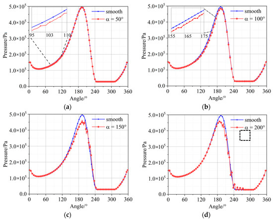
Figure 8.
Pressure profiles of the journal bearing centerlines. (a) α = 50°; (b) α = 100°; (c) α = 150°; (d) α = 200°; (e) α = 250°; (f) pressure profile of single texture.
Figure 8f represents the pressure distribution of single texture in the non-cavitation region, which is marked in black frame in Figure 8d. In Figure 8f, the greyscale cross-hatched area below 4.45 × 10⁵ Pa represents the pressure drop due to the divergence at the entrance of texture and the cross-hatched area above 4.45 × 10⁵ Pa represents the pressure rise caused by convergence at the outlet of texture. When the lubricant flows through one texture, a slight micro-hydrodynamic pressure will generate as indicated by cross-hatched area above 4.45 × 10⁵ Pa. That means the positive load-carrying capacity caused by the pressure rise is greater than the negative load-carrying capacity caused by the pressure drop. From the enlarged view in Figure 8e, only positive load-carrying capacity will generate when textures are distributed in the cavitation region. However, these positive effect on load-carrying capacity is less than the negative effect caused by the increase of oil film, which is the main reason why the textures have a negative impact on the load-carrying capacity in the present work.
As described above, when textures are distributed in cavitation region, only the positive effects on load-carrying capacity generate. This is because the pressure will be limited to saturation pressure, if p < psat, which can be observed in Figure 9. The pressure of the smooth bearing will only be maintained at saturation pressure without the additional positive pressure. Therefore, only positive effects on load-carrying capacity will generate compared with the smooth bearings.
Figure 9.
Pressure profiles in cavitation region.
The mass fraction of vapor contours for smooth and textured journal bearings are shown in Figure 10. It can be seen that when the textures are distributed close to the cavitation region, the position where cavitation starts is advanced (from about 240° to about 220°). This will further enhance the positive load-carrying capacity generated by the cavitation effect, although the lifting effect is not significant relative to the overall load-carrying capacity of the bearing.
Figure 10.
Mass fraction of vapor contours. (a) smooth bearing; (b) α = 200°.
The inertia effect of single textures has been stated to generate additional load-carrying capacity. To investigate the inertia effect of textures in the whole journal bearing, the pressure profiles at the textures with and without considering the inertial effect are compared in Figure 11. Since the rotational speed used in the present work is only 600 rpm, there is no significant difference between them. However, it can still be observed that, the pressure profile considering the inertia effect slightly moves upward compared with that neglecting the inertia effect. It can be assumed that with the increase of rotational speed, a more significant inertia effect can be expected.
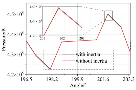
Figure 11.
Pressure comparison with and without considering the inertia effect.
3.2. Effect of Textures on the Friction Force
Friction forces under different textured geometries and positions are listed in Figure 12. ΔF means the percentage difference in friction force between smooth and textured bearings, defined as . It can be observed that the textured bearings have a lower friction force under all the cases compared with the smooth bearing. Especially when the textures are distributed near the minimum oil film (225° in the present study), the friction reduction effect is more significant. Combined with the results of load-carrying capacity in Figure 6, the friction force is reduced when the textures are distributed downstream of the high-pressure region (250°). Meanwhile, the load-carrying capacity is not affected significantly but with a slight decrease. Especially for W2D50, the reduction in friction force is 6.61% while the decrease in load-carrying capacity is only 0.59%. This marks a significant advantage of textured journal bearings.
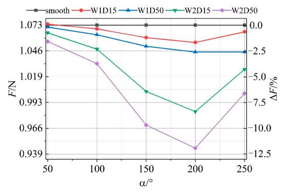
Figure 12.
Friction force under different textured geometries and positions.
The wall shear stress contours of W1D50 under different textured positions are given below. It can be observed that for the smooth bearing, the maximum wall shear stress is at the minimum oil film. No matter where the textures are distributed, the wall shear stress at the textures is very low. However, when the textures are distributed at the minimum oil film, the maximum wall shear stress increases, as shown in Figure 13d,e.
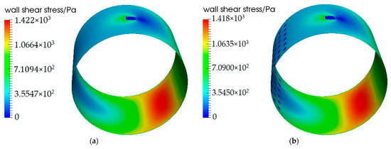
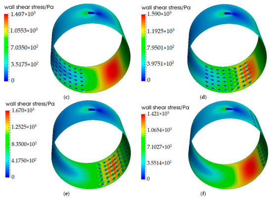
Figure 13.
Wall shear stress contours under different textured positions. (a) smooth bearing; (b) α = 50°; (c) α = 100°; (d) α = 150°; (e) α = 200°; (f) α = 250°.
The profiles of wall shear stress on the bearing centerline are compared between smooth and textured bearings with different textured positions, which are shown in Figure 14. It can be found that the wall shear stress can be decreased to nearly 0 at the textures because of the increase of oil film. As the textured zone gradually approaches the minimum oil film, the decreasing of wall shear stress at the textures is more significant, but also accompanied by the increase of wall shear stress between textures, which can be found in Figure 14c,d.
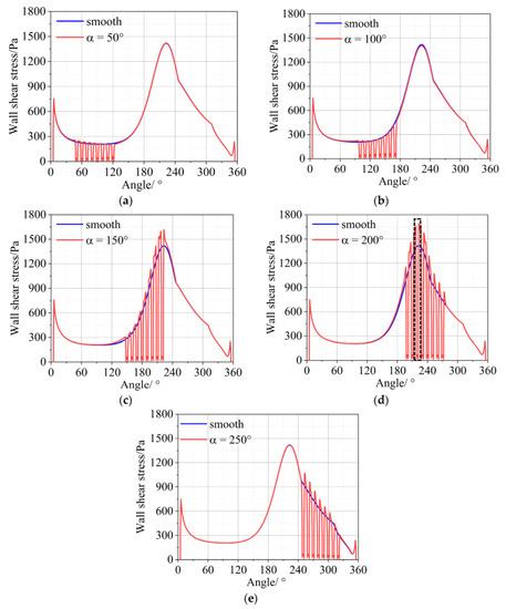
Figure 14.
Shear stress profiles of the journal bearing centerlines. (a) α = 50°; (b) α = 100°; (c) α = 150°; (d) α = 200°; (e) α = 250°.
To analyze the reason of higher wall shear stress between textures, the internal flow streamlines for the textures at the minimum oil film (marked by black frame in Figure 14d) are captured. From the streamlines in the whole textures in Figure 15, it can be found that the vortex will be generated inside the textures and the flow within the vortex will circulate in the textures without flowing out.
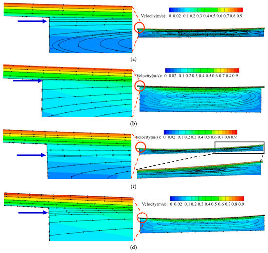
Figure 15.
Streamlines under different textured geometries. (a) Streamlines for W1D15; (b) Streamlines for W1D50; (c) Streamlines for W2D15; (d) Streamlines for W2D50.
From the streamlines at the entrance of the textures in the left side of Figure 15, the inlet suction effect caused by the lager pressure gradient at the entrance of textures can be found, which increases the lubricant flowing into the textures. Consequently, more lubricant also flows out from the outlet of textures under the steady state, which will cause a lager flow rate at the minimum oil film compared with the smooth bearing. It can be observed that under the same textured depth, the wider textures have a lager inflow area. Additionally, there is an interesting point that under the same textured width, the shallow textures have a larger inflow area. Because the increased depth of the textures leads to an increasing of vortex height at the inlet of texture, which interferes with the inflow area. Therefore, more lubricant can be sucked into the shallow textures and further cause a lager flow rate at the minimum oil film.
To elucidate the influence of the flow rate at the minimum oil film on the maximum shear stress between textures, the flow rates at the minimum oil film are integrated and shown in Figure 16. Compared with the smooth bearing, all the textured bearings have a lager flow rate at the minimum oil film. The maximum wall shear is proportional to the lubricant flow rate at the minimum oil film, which means a lager flow rate at the minimum oil film causes a lager maximum wall shear stress. It can also be observed that the wider texture has a greater flow rate at the outlet of textures. The flow rate of deep texture is lower than that of shallow texture. Therefore, the higher wall shear stress between textures could be explained by the inlet suction effect at the entrance of textures. That means more fluid flows out from the outlet of textures under the steady state. Consequently, the flow rate at the minimum oil film increases compared with the smooth bearing, which causes a lager wall shear stress here. Meanwhile, the vortex inside the textures will influence the inflow area of textures and further affect the maximum shear stress at the minimum oil film.
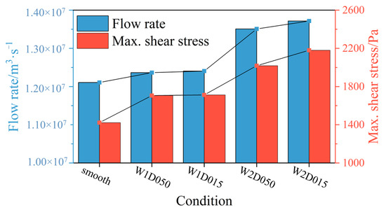
Figure 16.
Relationship between the flow rate and the maximum shear stress.
3.3. Effect of Lubrication Film on the Microflow in Textures
From the above discussion, it can be concluded that the microflow inside textures can significantly influence the macro-hydrodynamic lubrication film. In this section, the effect of lubrication film with different film thickness and pressure distributions on the microflow inside textures is studied. Based on the textured position marked in Figure 14d, the internal streamlines of W2D50 in other four distribution positions are also captured and compared. The selected textures at five distribution positions are shown in Figure 17.
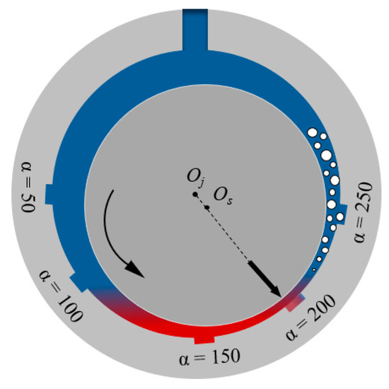
Figure 17.
Positions of five selected textures. Oj means center of journal bearing, Os means center of shaft, α means starting angle of textured zone.
The internal flow of textures at the five different positions according to Figure 17 is shown in Figure 18. It can be observed that when the textures are located upstream of the minimum oil film, the vortex centers inside the textures move forward to the upstream side, as shown in Figure 18a,b. When the texture is located at the low-pressure region of the bearing which is also the cavitation region, the vortex centers move towards the downstream of the bearing as shown in Figure 18e. It can be concluded that the vortex center inside the textures moves away from the high-pressure region. As can also be observed from the enlarged streamlines at the textured entrance, the textures at the high-pressure region and the minimum oil film region have a larger inflow area, as shown in Figure 18c,d, respectively. That also means more lubricant flows into the textures in these regions.
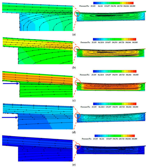
Figure 18.
Streamlines under different textured positions. (a) α = 50°; (b) α = 100°; (c) α = 150°; (d) α = 200°; (e) α = 250°.
4. Conclusions
In the present work, the hydrodynamic lubrication models of textured journal bearings are built to investigate the effect of textured geometries and positions on the lubrication performance of journal bearings. Then, the local lubrication mechanisms of textures in journal bearings are analyzed from microflow perspective inside textures. Furthermore, the interactions between textures and the film formation in the whole bearing are considered. Based on the results obtained, the conclusions are summarized in the following:
- (1)
- The micro-hydrodynamic pressure of textures can be generated on one hand by the limiting pressure drop (cavitation) in the divergent gap and on the other hand by the inertia effect. Meanwhile, the increase of film thickness in textured zone disrupts the continuity of original high-pressure region of journal bearings. In the current work, the positive micro-hydrodynamic pressure effect on the load-carrying capacity is less than the negative effect caused by the discontinuity of high-pressure region, thereby the load-carrying capacity decreases by 0.3% to 25.3%.
- (2)
- Textures can significantly reduce the wall shear stress. This effect can be explained by the increased film thickness, which is most dominant when the textures are located in the region of minimum film thickness. However, it has a negative effect on the load-carrying capacity. In contrast, placing textures downstream of the high-pressure region leads to a reduced friction force, with a less severe loss of load-carrying capacity.
- (3)
- The vortex inside the textures will influence the inflow area of textures and further affect the maximum shear stress at the minimum oil film. The vortex center inside the texture moves away from the high-pressure region and the textures in the high-pressure region and the minimum oil film region have a larger lubricant inflow area.
The present work analyzes the local lubrication mechanisms of the textures in journal bearings from microflow perspective, while considering the interactions between textures and the film formation in the whole bearing. This work provides the fundamental reference and knowledge in the design and optimization procedure of textured journal bearings. However, due to the complexity in terms of a huge amount of design parameters, textures can be detrimental if the inappropriate value is selected. When optimizing the textures, the external load needs to be specified in the future work.
Author Contributions
Conceptualization, Y.W., F.K. and G.J.; methodology, Y.W. and S.Z.; software Y.W. and S.Z.; validation, Y.W.; formal analysis, Y.W., F.K., G.J., S.Z. and S.v.G.; investigation, Y.W.; data curation, Y.W.; writing—original draft preparation, Y.W.; writing—review and editing, Y.W., G.J., F.K., S.Z. and S.v.G.; visualization, Y.W.; supervision, G.J. and F.K.; funding acquisition, Y.W., G.J. and F.K. All authors have read and agreed to the published version of the manuscript.
Funding
This research was funded by China Scholarship Council (No. CSC202106450023).
Data Availability Statement
Not applicable.
Conflicts of Interest
The authors declare no conflict of interest.
References
- Balakrishnan, S.; Baker, C.E.; Rahnejat, H. Fundamentals of hydrodynamic journal bearings: An analytical approach. In Tribology and Dynamics of Engine and Powertrain; Woodhead Publishing: Cambridge, UK, 2010; pp. 591–614. [Google Scholar]
- Bouyer, J.; Alexandre, Y.; Fillon, M. Experimental investigation on the influence of a multi-scratched shaft on hydrodynamic journal bearing performance. Tribol. Int. 2021, 153, 106543. [Google Scholar] [CrossRef]
- Xiang, G.; Yang, T.; Guo, J.; Wang, J.; Liu, B.; Chen, S. Optimization transient wear and contact performances of water-lubricated bearings under fluid-solid-thermal coupling condition using profile modification. Wear 2022, 502–503, 204379. [Google Scholar] [CrossRef]
- König, F.; Sous, C.; Jacobs, G. Numerical prediction of the frictional losses in sliding bearings during start-stop operation. Friction 2021, 9, 583–597. [Google Scholar] [CrossRef]
- Xie, Z.; Jiao, J.; Yang, K. Theoretical and experimental study on the fluid-structure-acoustic coupling dynamics of a new water lubricated bearing. Tribol. Int. 2023, 177, 107982. [Google Scholar] [CrossRef]
- Rasep, Z.; Muhammad Yazid, M.; Samion, S. Lubrication of textured journal bearing by using vegetable oil: A review of approaches, challenges, and opportunities. Renew. Sustain. Energy Rev. 2021, 146, 111191. [Google Scholar] [CrossRef]
- Rom, M.; König, F.; Müller, S.; Jacobs, G. Why homogenization should be the averaging method of choice in hydrodynamic lubrication. Appl. Eng. Sci. 2021, 7, 100055. [Google Scholar] [CrossRef]
- Grabon, W.; Koszela, W.; Pawlus, P.; Ochwat, S. Improving tribological behaviour of piston ring–cylinder liner frictional pair by liner surface texturing. Tribol. Int. 2013, 61, 102–108. [Google Scholar] [CrossRef]
- Li, Q.; Wang, Y.; Zhang, S.; Xu, W.; Bai, L.; Wang, Z. Investigation and optimization of textured thrust bearings with spirally distributed dimples using multi-objective optimization method. ILT 2020, 72, 749–759. [Google Scholar] [CrossRef]
- Rosenkranz, A.; Heib, T.; Gachot, C.; Mücklich, F. Oil film lifetime and wear particle analysis of laser-patterned stainless steel surfaces. Wear 2015, 334–335, 1–12. [Google Scholar] [CrossRef]
- Yamakiri, H.; Sasaki, S.; Kurita, T.; Kasashima, N. Effects of laser surface texturing on friction behavior of silicon nitride under lubrication with water. Tribol. Int. 2011, 44, 579–584. [Google Scholar] [CrossRef]
- Brunetière, N.; Tournerie, B. Numerical analysis of a surface-textured mechanical seal operating in mixed lubrication regime. Tribol. Int. 2012, 49, 80–89. [Google Scholar] [CrossRef]
- Zhang, H.; Hua, M.; Dong, G.; Zhang, D.; Chin, K.-S. A mixed lubrication model for studying tribological behaviors of surface texturing. Tribol. Int. 2016, 93, 583–592. [Google Scholar] [CrossRef]
- Imai, N.; Kato, T. Effects of texture patterns on hydrodynamic and mixed lubrication characteristics. Proc. Inst. Mech. Eng. Part J J. Eng. Tribol. 2013, 227, 898–904. [Google Scholar] [CrossRef]
- König, F.; Rosenkranz, A.; Grützmacher, P.G.; Mücklich, F.; Jacobs, G. Effect of single- and multi-scale surface patterns on the frictional performance of journal bearings—A numerical study. Tribol. Int. 2020, 143, 106041. [Google Scholar] [CrossRef]
- Grützmacher, P.G.; Rosenkranz, A.; Szurdak, A.; König, F.; Jacobs, G.; Hirt, G.; Mücklich, F. From lab to application—Improved frictional performance of journal bearings induced by single- and multi-scale surface patterns. Tribol. Int. 2018, 127, 500–508. [Google Scholar] [CrossRef]
- Wang, Y.; Li, Q.; Zhang, S.; Tang, X.; Xu, W.; Wang, Z. Analysis of turbulence and blocking effects on loading capacity for elementary texture cells of infinite width under water lubrication. ILT 2021, 73, 103–112. [Google Scholar] [CrossRef]
- Gropper, D.; Wang, L.; Harvey, T.J. Hydrodynamic lubrication of textured surfaces: A review of modeling techniques and key findings. Tribol. Int. 2016, 94, 509–529. [Google Scholar] [CrossRef]
- Ma, C.; Duan, Y.; Yu, B.; Sun, J.; Tu, Q. The comprehensive effect of surface texture and roughness under hydrodynamic and mixed lubrication conditions. Proc. Inst. Mech. Eng. Part J J. Eng. Tribol. 2017, 231, 1307–1319. [Google Scholar] [CrossRef]
- Dobrica, M.B.; Fillon, M.; Pascovici, M.D.; Cicone, T. Optimizing surface texture for hydrodynamic lubricated contacts using a mass-conserving numerical approach. Proc. Inst. Mech. Eng. Part J J. Eng. Tribol. 2010, 224, 737–750. [Google Scholar] [CrossRef]
- Fowell, M.T.; Medina, S.; Olver, A.V.; Spikes, H.A.; Pegg, I.G. Parametric study of texturing in convergent bearings. Tribol. Int. 2012, 52, 7–16. [Google Scholar] [CrossRef]
- Rosenkranz, A.; Grützmacher, P.G.; Gachot, C.; Costa, H.L. Surface Texturing in Machine Elements—A Critical Discussion for Rolling and Sliding Contacts. Adv. Eng. Mater. 2019, 21, 1900194. [Google Scholar] [CrossRef]
- Etsion, I. State of the Art in Laser Surface Texturing. J. Tribol. 2005, 127, 248–253. [Google Scholar] [CrossRef]
- Marian, M.; Almqvist, A.; Rosenkranz, A.; Fillon, M. Numerical micro-texture optimization for lubricated contacts—A critical discussion. Friction 2022, 10, 1772–1809. [Google Scholar] [CrossRef]
- Hamilton, D.B.; Walowit, J.A.; Allen, C.M. A Theory of Lubrication by Microirregularities. J. Basic Eng. 1966, 88, 177–185. [Google Scholar] [CrossRef]
- Etsion, I.; Kligerman, Y.; Halperin, G. Analytical and Experimental Investigation of Laser-Textured Mechanical Seal Faces. Tribol. Trans. 1999, 42, 511–516. [Google Scholar] [CrossRef]
- Arghir, M.; Roucou, N.; Helene, M.; Frene, J. Theoretical Analysis of the Incompressible Laminar Flow in a Macro-Roughness Cell. J. Tribol. 2003, 125, 309–318. [Google Scholar] [CrossRef]
- Sahlin, F.; Glavatskih, S.B.; Almqvist, T.; Larsson, R. Two-Dimensional CFD-Analysis of Micro-Patterned Surfaces in Hydrodynamic Lubrication. J. Tribol. 2005, 127, 96–102. [Google Scholar] [CrossRef]
- Keller, D.; Jacobs, G.; Neumann, S. Development of a Low-Friction Radial Shaft Seal: Using CFD Simulations to Optimise the Microstructured Sealing Lip. Lubricants 2020, 8, 41. [Google Scholar] [CrossRef]
- Fowell, M.; Olver, A.V.; Gosman, A.D.; Spikes, H.A.; Pegg, I. Entrainment and Inlet Suction: Two Mechanisms of Hydrodynamic Lubrication in Textured Bearings. J. Tribol. 2007, 129, 336–347. [Google Scholar] [CrossRef]
- Tønder, K. Hydrodynamic effects of tailored inlet roughnesses: Extended theory. Tribol. Int. 2004, 37, 137–142. [Google Scholar] [CrossRef]
- Tala-Ighil, N.; Maspeyrot, P.; Fillon, M.; Bounif, A. Effects of surface texture on journal-bearing characteristics under steady-state operating conditions. Proc. Inst. Mech. Eng. Part J J. Eng. Tribol. 2007, 221, 623–633. [Google Scholar] [CrossRef]
- Tala-Ighil, N.; Fillon, M.; Maspeyrot, P. Effect of textured area on the performances of a hydrodynamic journal bearing. Tribol. Int. 2011, 44, 211–219. [Google Scholar] [CrossRef]
- Brizmer, V.; Kligerman, Y. A Laser Surface Textured Journal Bearing. J. Tribol. 2012, 134, 031702. [Google Scholar] [CrossRef]
- Kango, S.; Sharma, R.K.; Pandey, R.K. Thermal analysis of microtextured journal bearing using non-Newtonian rheology of lubricant and JFO boundary conditions. Tribol. Int. 2014, 69, 19–29. [Google Scholar] [CrossRef]
- Usman, A.; Park, C.W. Numerical optimization of surface texture for improved tribological performance of journal bearing at varying operating conditions. ILT 2018, 70, 1608–1618. [Google Scholar] [CrossRef]
- Vlădescu, S.-C.; Fowell, M.; Mattsson, L.; Reddyhoff, T. The effects of laser surface texture applied to internal combustion engine journal bearing shells—An experimental study. Tribol. Int. 2019, 134, 317–327. [Google Scholar] [CrossRef]
- Singh, N.; Awasthi, R.K. Influence of texture geometries on the performance parameters of hydrodynamic journal bearing. Proc. Inst. Mech. Eng. Part J J. Eng. Tribol. 2021, 235, 2056–2072. [Google Scholar] [CrossRef]
- Meng, F.M.; Zhang, L.; Liu, Y.; Li, T.T. Effect of compound dimple on tribological performances of journal bearing. Tribol. Int. 2015, 91, 99–110. [Google Scholar] [CrossRef]
- Liang, X.; Liu, Z.; Wang, H.; Zhou, X.; Zhou, X. Hydrodynamic lubrication of partial textured sliding journal bearing based on three-dimensional CFD. ILT 2016, 68, 106–115. [Google Scholar] [CrossRef]
- Shinde, A.B.; Pawar, P.M. Multi-objective optimization of surface textured journal bearing by Taguchi based Grey relational analysis. Tribol. Int. 2017, 114, 349–357. [Google Scholar] [CrossRef]
- Arif, M.; Shukla, D.K.; Kango, S.; Sharma, N. Implication of Surface Texture and Slip on Hydrodynamic Fluid Film Bearings: A Comprehensive Survey. Tribol. Online 2020, 15, 265–282. [Google Scholar] [CrossRef]
- Yamada, H.; Taura, H.; Kaneko, S. Numerical and Experimental Analyses of the Dynamic Characteristics of Journal Bearings With Square Dimples. J. Tribol. 2018, 140, 011703. [Google Scholar] [CrossRef]
- Yong, H.; Balendra, R. CFD analysis on the lubrication behaviours of journal bearing with dimples. In Proceedings of the 2009 International Conference on Mechatronics and Automation, Changchun, China, 18 September 2009. [Google Scholar]
- Wang, W.; He, Y.; Li, Y.; Wei, B.; Hu, Y.; Luo, J. Investigation on inner flow field characteristics of groove textures in fully lubricated thrust bearings. ILT 2018, 70, 754–763. [Google Scholar] [CrossRef]
- Wang, W.; He, Y.; Zhao, J.; Li, Y.; Luo, J. Numerical optimization of the groove texture bottom profile for thrust bearings. Tribol. Int. 2017, 109, 69–77. [Google Scholar] [CrossRef]
- Feldermann, A.; Neumann, S.; Jacobs, G. CFD simulation of elastohydrodynamic lubrication problems with reduced order models for fluid–structure interaction. Tribol.-Mater. Surf. Interfaces 2017, 11, 30–38. [Google Scholar] [CrossRef]
- Sagar, H.J.; el Moctar, O. Dynamics of a cavitation bubble near a solid surface and the induced damage. J. Fluids Struct. 2020, 92, 102799. [Google Scholar] [CrossRef]
- Greenshields, C.J.; Weller, H.G. Notes on Computational Fluid Dynamics: General Principles; CFD Direct Limited: Reading, UK, 2022. [Google Scholar]
- Wallis, G.B. One-Dimensional Two-Phase Flow; Dover Publications Inc.: Garden City, NY, USA, 2020. [Google Scholar]
- Wen, S.; Huang, P. Principles of Tribology (Second Edition): Mo Ca Xue Yuan Li (Di 2 Ban)/Wen Shizhu, Huang Ping Zhu, Di 1 Ban; Tsinghua University Press: Beijing, China, 2017. [Google Scholar]
- Gao, G.; Yin, Z.; Jiang, D.; Zhang, X. Numerical analysis of plain journal bearing under hydrodynamic lubrication by water. Tribol. Int. 2014, 75, 31–38. [Google Scholar] [CrossRef]
- Lin, Q.; Bao, Q.; Li, K.; Khonsari, M.M.; Zhao, H. An investigation into the transient behavior of journal bearing with surface texture based on fluid-structure interaction approach. Tribol. Int. 2018, 118, 246–255. [Google Scholar] [CrossRef]
- Xie, Z.; Jiao, J.; Yang, K.; He, T.; Chen, R.; Zhu, W. Experimental and numerical exploration on the nonlinear dynamic behaviors of a novel bearing lubricated by low viscosity lubricant. Mech. Syst. Signal Process. 2023, 182, 109349. [Google Scholar] [CrossRef]


Disclaimer/Publisher’s Note: The statements, opinions and data contained in all publications are solely those of the individual author(s) and contributor(s) and not of MDPI and/or the editor(s). MDPI and/or the editor(s) disclaim responsibility for any injury to people or property resulting from any ideas, methods, instructions or products referred to in the content. |
© 2023 by the authors. Licensee MDPI, Basel, Switzerland. This article is an open access article distributed under the terms and conditions of the Creative Commons Attribution (CC BY) license (https://creativecommons.org/licenses/by/4.0/).