Article

A Contribution to Experimental Identification of Frequency-Dependent Dynamic Coefficients of Tilting-Pad Journal Bearings with Centered and Off-Centered Pivot

Institute of Tribology, Clausthal University of Technology, 38678 Clausthal-Zellerfeld, Germany
*
Author to whom correspondence should be addressed.
Lubricants 2023, 11(10), 428; https://doi.org/10.3390/lubricants11100428
Submission received: 22 August 2023 / Revised: 13 September 2023 / Accepted: 29 September 2023 / Published: 3 October 2023
(This article belongs to the Special Issue Condition Monitoring and Simulation Analysis of Bearings)

Abstract

:
Linearized dynamic bearing parameters and models are of essential interest for rotordynamic analyses in machine design. This paper experimentally studies the impact of pad preload and pivot offset on the frequency-dependent characteristics of dynamic stiffness (K) and damping coefficients (C) of a KC-model for tilting-pad journal bearings. For this purpose, two four-pad test bearing configurations (preload m = 0.17 , pivot offset 0.5 and preload m = 0.47 , pivot offset 0.6) that differ highly with respect to the pad design parameters are investigated. Contributing effects on the results due to geometric differences are excluded as far as possible, as only one aligning ring and one pivot support design is used. The tests are conducted on a high-performance test rig for surface speeds up to 140 m/s and excitation frequencies of 500 Hz. Significant deviations between the two bearings are identified that generally match theoretically predicted differences and, therefore, contribute to the validation of dynamic bearing modeling.

1. Introduction

Generally, journal bearings respond with a nonlinear modification of the fluid film forces from a change in journal eccentricity. However, linearized bearing properties represent a good approximation of dynamic bearing behavior in many practical cases and are an essential input parameter for time-efficient rotordynamic analyses. Several models with different levels of detail exist for the description of the dynamic behavior of tilting-pad journal bearings. The KC-model is the simplest one covering the cross-coupled effects in journal bearings. It consists of 2 × 2 stiffness and damping matrices. Due to its simplicity and clarity, it is the most widely used dynamic bearing model, allowing comparably simple engineering judgments. However, from a theoretical point of view, the description of dynamic tilting-pad behavior by the eight load- and speed-dependent KC-coefficients is generally insufficient for two major reasons. First, the additional acceleration coefficients required to characterize dynamic bearing properties if fluid inertia effects cannot be neglected, as described by Reinhardt and Lund [1]. Second, the analysis of tilting-pad kinematics provides a vibration frequency dependence of the dynamic coefficients in the KC-model representation [2]. While the first effect is only relevant for a limited number of applications, the second one is present throughout the entire operating range and is part of the subsequent investigations in this paper. A frequency-independent description of the dynamic bearing properties over a wide frequency range is only provided by the full tilting-pad bearing model [3,4,5,6].
For the experimental determination of the dynamic coefficients, the test rig design with a test bearing located between two support bearings on one shaft established by Glienicke [7] has prevailed. For a sinusoidal excitation, the equations of motion of this arrangement lead to determination equations for each of the four stiffness and damping coefficients of the KC-model in the time domain. Rouvas and Childs [8] extend the identification procedure to the frequency domain and use a so-called “pseudo-random” excitation. Starting with ref. [9], different studies led by Childs, e.g., [10,11,12], indicate a good approximation of the identified frequency-dependent real part of the measured transfer functions using a combination of frequency-independent stiffness coefficients and virtual mass coefficients. The gradient of the particular imaginary part of the measured frequency response is approximated using a constant parameter representing the damping coefficient. Therefore, the authors propose a KCM-model structure with an additional virtual mass matrix (M) that cancels the previously present frequency dependence and results in frequency independence and, thus, constant dynamic coefficients.
The KC- and KCM-models are reduced to the degrees of freedom of the rotor and stator in the x- and y-directions. Several researchers theoretically describe dynamic tilting-pad bearing behavior considering the additional degrees of freedom of the pads in an unreduced manner [2,3,6,13,14]. However, experimental validation of these models is complex, because the motion of the pad must be accurately measured and separated into different degrees of freedom, as shown by Wilkes and Childs [15]. Therefore, most experimental setups for measuring the dynamic coefficients are based on the equations of motion of rotor and stator in the x- and y-direction, resulting in a frequency-dependent response of the real part and, consequently, in frequency-dependent dynamic stiffness coefficients in the KC-model representation. For the damping, the measurements generally show a linear response of the imaginary part over frequency, which indicates no significant frequency dependence for the damping coefficients. In [16], a weak deviation from a constant damping value is shown.
Theoretical and experimental investigations additionally confirm the influence of the structural elasticities of the bearing on its dynamic coefficients, in particular, by the series connection of pivot support stiffness and lubricating film, known as “hardening effect” [11,17,18,19]. Since the frequency-dependent effects of limited pivot support stiffness and lubricant film have opposing tendencies [20], the influence of the single aspects on measured results cannot always be clearly assigned. Additionally, the measurement of dynamic journal bearing properties requires a high level of experimental setup and measurement technology that ensures the application of the intended loads, the precision of the transducers, and reliable data acquisition with the exclusion of interfering effects as far as possible. It represents one of the most challenging task in bearing identification. This partly results in contradictory findings due to the complexity of implementing reliable identification procedures and deviating boundary conditions. For example, opposite tendencies for the impact of excitation frequency on dynamic coefficients are shown by measurements in [10,21,22,23], while only slight frequency dependence of the dynamic bearing coefficients is found in [24]. Consequently, there is a need for distinct experimental data regarding the frequency dependence of dynamic coefficients for tilting-pad journal bearings that ideally enables a separation of the impact of the single abovementioned influencing effects.
The tendencies of single effects such as pivot stiffness, pad preload, or pivot position on the frequency dependence of the KC-model dynamic coefficients has been theoretically studied by many authors and provides similar characteristics over the excitation frequency [2,17,20,22,24,25,26,27,28,29,30]. While the frequency dependence of KC-coefficients is proven experimentally, too [10,11,12,16,21,22,23,24,31,32,33,34,35,36], there is a much higher uncertainty regarding its concrete expression. This paper contributes to the experimental identification of frequency-dependent dynamic coefficients in the KC-model representation up to highest surface speeds and excitation frequencies, in order to provide more detailed validation data and more accurate insights into local characteristics. Hereby, a special focus is put on the impact of excitation frequency on damping coefficients. Furthermore, particular emphasis is given to the frequency-dependent effect of the dynamic coefficients created by the pressure generation in the lubricating film. For this purpose, the investigated test bearings vary with regards to the pad preload and pivot offset, whereas other properties and boundary conditions remain unchanged as far as possible.

2. Method and Test Equipment

2.1. Test Rig

The test rig allows multiple setups and follows the general layout described by Glienicke [7] and Childs and Hale [9]. Figure 1 shows the principle design and the main components of the test facility [37,38]. Two fluid film journal bearings (2, 3) support the test rotor (1). The test bearing (4) is located centrally between the two support bearings and is mounted in a bearing stator (5). Six transverse elastic stringers (7) align the bearing stator axially within the test rig. The bearing stator is connected to two electrohydraulic shakers (8) arranged orthogonally to each other, which apply both the static and dynamic forces. The applied load to the test bearing housing is measured in two lateral elastic rods (9) using strain gauges. The inertia force of the bearing and the stator during testing is determined by the excited mass and two accelerometers, which are attached to both sides of the bearing stator. The mass of the complete bearing assembly including all excited parts was separately measured with a weighing scale before test rig assembly and could be verified through a baseline test, i.e., Re ( H x x ) and Re ( H y y ) show a horizontal characteristic versus frequency. Two pairs of eddy current sensors are attached to the bearing stator to measure the relative motion at the front and rear side of the bearing between rotor and stator (10) (front side = a, back side = b). A flexible coupling (6) connects the test rotor to the drive unit. A 630 kW electric motor with a maximum speed of 6000 rpm results in combination with a planetary gearbox into the maximum operating speed of the test rotor of 30,000 rpm. The test and support bearings are lubricated separately. Lubricant supply pressure, inlet temperature, and flow rate are set and monitored for each bearing. Table 1 shows the operating principle and nominal nonrepeatability of the sensors used in this study.

2.2. Experimental Procedure

Rouvas and Childs [8] developed a method for the experimental determination of dynamic coefficients based on a system identification procedure. They identify a real and imaginary part of the bearing transfer function. Results can either be fit to a KCM dynamic bearing model or to the KC-model used here [24]. Figure 2 outlines a schematic representation of the main components of the test setup including the pads 1 to 4. While the load is applied among the main axes of the 1,2 coordinate system, all forthcoming evaluations are related to the x,y coordinate system. The positive y axis is aligned with the static load direction. These are the test bearings, including pads and the bearing stator. Its mass is symbolized by m s . Moreover, Figure 2 illustrates the interaction of the single components and the external forces and the locations of the sensors.
To determine the system characteristics, Y = H · U , the force, displacement, and acceleration signals measured in the time domain are transformed into the frequency domain using the discrete Fourier transformation, F k = F ( f k ) , A k = F ( a k ) , and D k = F ( d k ) . The resulting system of equations, including the stator mass m s , is written as follows:
F x m s A x F y m s A y Y = H x x H x y H y x H y y H · D x D y U
The unknown transfer functions H i j are obtained by two pair measurements in each direction. Thus, Equation (1) results in
F x x m s A x x F x y m s A x y F y x m s A y x F y y m s A y y = H x x H x y H y x H y y D x x D x y D y x D y y
The first index in Equation (2) represents the orientation of the coordinate axis; see Figure 2. The second index represents the direction of excitation.
The evaluation procedure uses the power spectral density method described in ref. [9]. An unbiased estimate for the transfer function H i j is given according to Bendat and Piersol [39] by
H i j = G i j G i i
with the cross-density G i j and the autodensity function G i i . The spectral densities are determined by
G i j = 2 T I * ( ω ) · J ( ω )
Here, a finite signal length T, the one-sided Fourier transform of the low-noise (ideally noise-free) signal I ( ω ) , and the one-sided Fourier transform of the noisy signal J ( ω ) are used. If this approach is applied for the multidimensional system in Figure 2 and solved for the unknowns H i j according to [8], the following system of equations can be used to calculate the transfer function:
H x x H x y H y x H y y = 1 m s G f x x a x x G f x x f x x G f y y f x y G f y y f y y m s G f y y a x y G f y y f y y G f y y f y x G f x x f x x m s G f x x a y x G f x x f x x 1 m s G f y y a y y G f y y f y y · G f x x d x x G f x x f x x G f y y d x y G f y y f y y G f x x d y x G f x x f x x G f y y d y y G f y y f y y 1
The measured force signals are relatively clean compared with the noisy acceleration and displacement signals. Therefore, the Fourier-transformed force signal F i i represents the first index in Equation (4). For each frequency, Equation (5) is evaluated successively. Only at the excited frequencies can reliable results be expected.
The dynamic coefficients are determined using a multisine signal with N = 62 frequencies between 8 Hz and 496 Hz with a nominal spectral amplitude of 200 N, resulting in an alternating excitation force in the time domain with a peak-to-peak value of about ±1.5 kN. To reduce the peak factor of the target signal, a phase shift suggested by Schroeder [40] of θ n = π n 2 N is applied. Since the system between the controller and the force sensors has a predetermined transmission behavior, an iteratively learning control algorithm modifies the force signal for the shakers to match the bearing excitation force to the target signal. The optimized signal and the selected force level allow the application of high excitation frequencies while preventing significant nonlinearity of the fluid film properties. The system is excited alternately in the d 1 and d 2 direction, and the measurands force, relative displacement, and stator acceleration are recorded simultaneously. The measurement data are monitored with a sampling rate of approximately 32.6 kHz and without additional filters. At all operating conditions, a set consisting of 32 measurement repetitions with a sampling time of 8 s is performed. Dividing these sets into sections of 1 s yields n = 256 signal pairs at each operating point.
Considering inertia, stiffness, and damping characteristics of the test rig, a baseline measurement is conducted with deactivated oil supply, zero journal rotation, and unrestricted bearing movability in its radial clearance. From the measurement, the transfer function of the nonrotating parts H i j , 0 is obtained. According to [9], the actual dynamic bearing characteristic is given by subtracting the base transfer function H i j , 0 from the transfer function H i j , T determined during bearing operation.
H i j = H i j , T H i j , 0 .

2.2.1. Error Estimation

According to GUM part 4.2.3 [41], the standard uncertainty for repeated measurements can be evaluated as follows:
u = ± t · s n ,
where s is the empirical standard deviation, n is the number of measurements, and t is obtained from the Student-t distribution. The combined uncertainty u for both measurements in Equation (6) can be determined according GUM part 5.1 [41] by
u ( ω ) = H ( ω ) H T ( ω ) · u T ( ω ) 2 + H ( ω ) H 0 ( ω ) · u 0 ( ω ) 2
In Equation (8), the partial derivative of the measurement during bearing operation (index T) results in H H T = 1 . The baseline measurement simplifies to H H 0 = 1 , respectively.

2.2.2. Evaluating the Frequency Response Using the KC-Model

Using the KC-model with its four stiffness k i j and damping coefficients c i j , the equations of motion for the investigated system in Figure 2 in the x- and y-direction are given by
f x m s a x = k x x x + c x x x ˙ + k x y y + c x y y ˙ f y m s a y = k y y y + c y y y ˙ + k y x x + c y x x ˙
Based on Equation (5), the measured frequency response is approximated by the following model function:
H i j ω = k i j + i ω c i j
The forthcoming results of this study, presented in the diagrams in Section 3, show the mean value x ¯ , oriented to the main load (y-direction) and the combined statistical uncertainty u with a 95 % confidence interval at each excited frequency.

2.3. Test bearing

The tests are conducted using a four-pad tilting-pad journal bearing with a rocker pivot design. A rocker pivot design is used to achieve a high pivot support stiffness. The setup for experimental validation consists of one bearing housing and two different pad layouts with different preloads and pivot offsets. Manufacturing deviations are thus reduced to a minimum. Figure 3 depicts the load configuration, the displacement sensor positions ( S 1 S 4 = front side, S 5 S 8 = back side), the temperature sensor position T 1 T 14 , the nominal load case, and the design of the investigated bearing. The bearing load direction is defined by the angle α and applied in the standard orientation between the pivot positions of pads #2 and #3 (LBP). A 1.5 mm thick Babbitt layer is applied to the steel pads. The distance between the pads’ sliding surface and the positions of the temperature sensors is 4.5 mm. Lube oil is supplied by three nozzles with a 2.9 mm diameter in each of the four spaces between pad regions. Aluminum end-plates limit the lubricant side flow in the lateral journal direction by fixed end seals with a clearance of approximately 3 times the nominal radial clearance of the bearing. Furthermore, the two identical lateral deflector plates contain fourteen non-equidistantly distributed radial holes, allowing oil drainage of the side flow. In addition to Figure 3, Table 2 provides geometry and boundary conditions about the test bearing setup and the lubricant properties.

3. Results

This investigation focuses on the impact of pad preload and pivot offset on frequency-dependent characteristics of measured KC-coefficients. To provide a short overview on expected results from a theoretical point of view, a brief introduction on predicted frequency-dependent characteristics is given first.

3.1. Predicted Frequency-Dependent Characteristics of KC-Coefficients

Two major effects dominate the frequency-dependent characteristics of theoretically predicted KC-coefficients. First, the combination of the fluid film stiffness and damping properties with the limited pivot stiffness leads to an increasing stiffness with rising excitation frequency [22]. Simultaneously, the damping slightly reduces [20]. Second, rigid pivot supports provoke decreasing stiffness with increasing excitation frequency, while the damping becomes higher at the same time [2]. The latter effect depends on pivot position as well as pad preload. Based on these relations, both effects have an opposing impact on frequency-dependent dynamic coefficients. Figure 4 shows the impact of the two effects reported in the literature schematically for the isotropic main stiffness and damping coefficients of a four-pad tilting-pad journal bearing with rigid and elastic pivot support. As described in [27,28,42], stiffness as well as damping are significantly reduced by limited pivot stiffness. Additionally, the frequency dependency of the damping coefficients in Figure 4 significantly decreases and, therefore, it is challenging to measure in the already difficult experimental procedure. The frequency-dependent characteristic of the main stiffness coefficients is dominated by the impact of the limited pivot stiffness, in particular in the supersynchronous range of excitations with Ω > 1. Generally, the impact of the pivot position and pad preload is less significant than the one of the pivot support stiffness and, therefore, challenging to identify in magnitude. Predictions in [26,43,44] show KC-coefficients that exhibit higher frequency-dependent characteristics for centrally supported bearings with small preloads than for eccentrically supported bearings with larger preloads. The effect is significantly reduced by the elasticity of the support, as shown in [20]. The geometrical preload and pivot offset of the two test bearings were chosen to gain a measurable difference in the bearing coefficients in the experiment. At the same time, the parameters are within the range of the industry standard.

3.2. Experimental Results

The subsequent experiments intend to identify the influence of the pad preload and pivot offset on the actual characteristics of the dashed lines in Figure 4. Before the experimental results of this task are studied, the impact of pivot support stiffness on measured results are investigated. The pivot support design of the two test bearings is identical and their deviations are limited to manufacturing uncertainties of the pads. In the experiments, great effort is given to ensure equal boundary conditions (i.e., the equivalent static load condition and alignment situation of the bearings) during both bearing tests. Additionally, tests at different oil flow rates according to a procedure described in [37] were performed in advance to ensure safe operation and to exclude the impact of starvation on the subsequent results to the author’s best knowledge. Figure 5 shows the measured maximum temperatures for different bearing loads of the two test bearings.

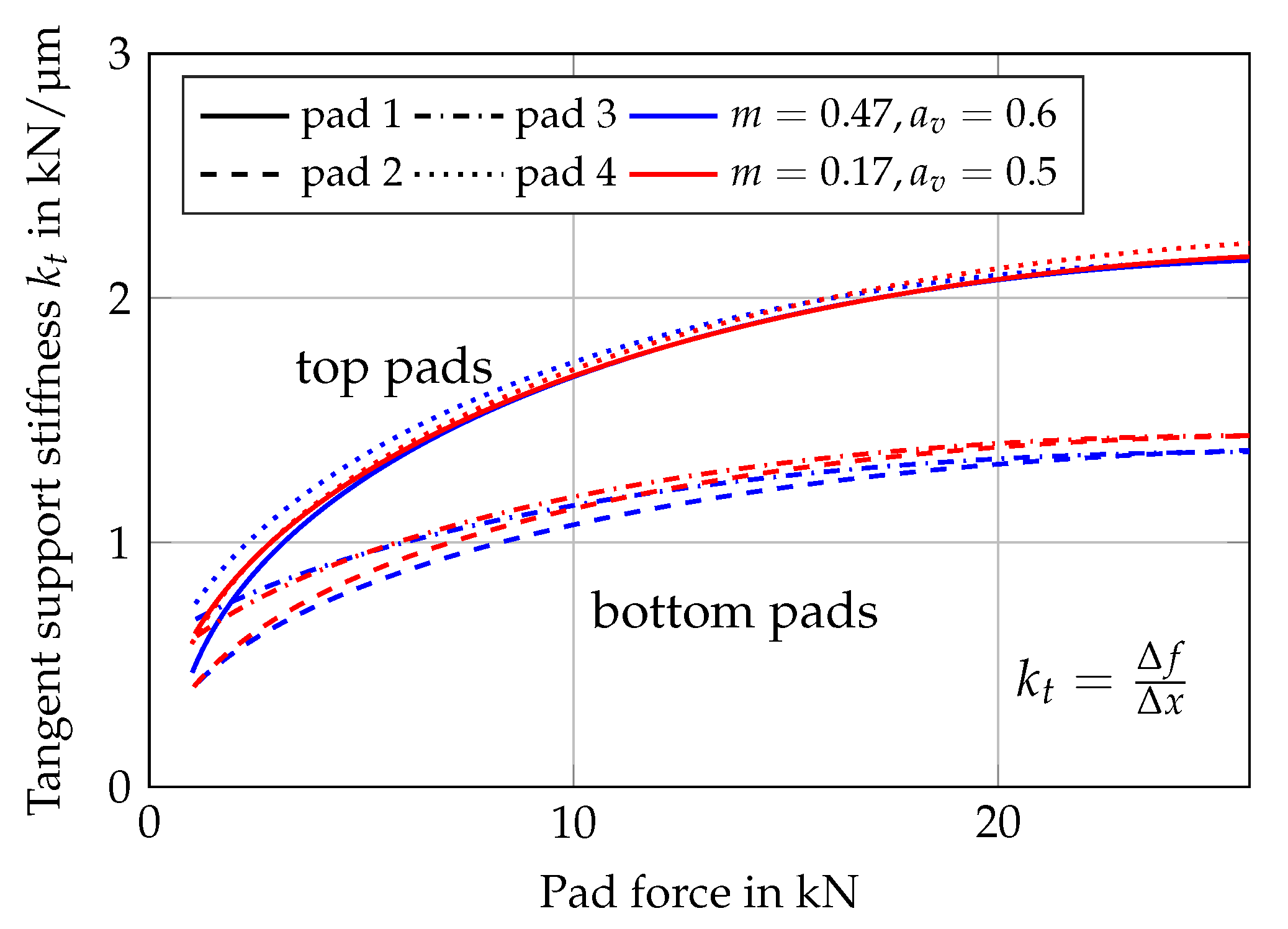
3.2.1. Support Stiffness

In the first step, verification tests to ensure the same support stiffness were performed at standstill, with the test bearing aligned and mounted in the bearing stator of the test rig. To determine the support stiffness of the bearing, the rotor was pushed towards the pivot positions while measuring the forces and deflection between the rotor and the bearing stator. The relevant support stiffness for the dynamic bearing coefficients is determined according to [27] as a tangent spring rate k t = Δ f Δ x . Figure 6 shows the relevant support stiffness k t for the two test bearings with differently loaded pads or directions.
Figure 6 illustrates differences between the measured support stiffness of the top and bottom pads of the bearing. Detailed investigations using FEM show a significant influence of the surrounding structure of the bearing stator. In particular, the connection of the bearing housing to the load cells leads to a higher stiffness of the bearing stator and, thus, to a direction-dependent deformation of the overall system. A comparison of the measured dynamic support stiffnesses of the two test bearings shows excellent agreement. Consequently, potentially measured differences in dynamic coefficients between the two experimental setups are almost completely caused by the different pressure distribution in the lubricant films of the two test bearings and not by the influence of the support stiffness. The tangent spring rate k t represents the overall support stiffness of the bearing and surrounding structure in combination with the contact between journal and pad. Its value is used in the predictions of several researchers to characterize the elasticities that are in series with the lubricant film, e.g., [19,20,22].

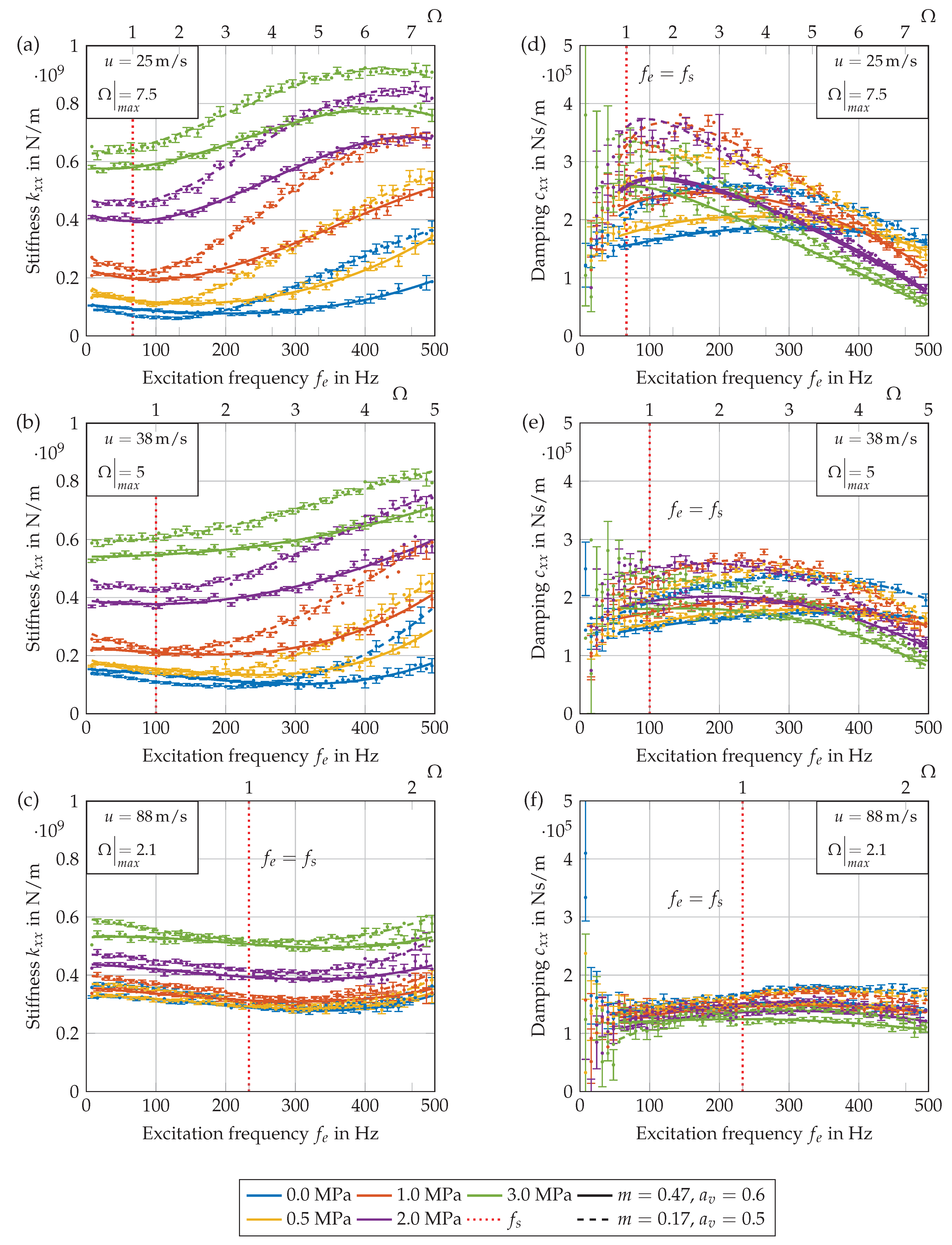
3.2.2. Influence of the Support Stiffness on the Dynamic Coefficients

The measured results show different pivot support stiffness for top (pad 1 and 4) and bottom pads (pad 2 and 3). However, the measured values represent not only the pivot support stiffness but a combination of pivot support and structure stiffness. This characteristic is used to analyze the influence of bearing elasticity on the dynamic bearing coefficients, as stiffness and damping coefficients of the bearing are dominated by the properties of the loaded pads.
To investigate the impact of structure elasticity, load is applied between pad 2 and 3 with α = 90 according to the nomenclature in Figure 3 as the first step. In the second step, load rotates by 180 and is directed between pad 1 and 4 with α = 270 . Figure 7 and Figure 8 show the effect of different support stiffnesses on the dynamic bearing coefficients in the x- and y-direction for different operating speeds at a unit load of 1.0 MPa. Due to the investigated load directions with the mechanical load applied between pivots, the bearing tends to show isotropic behavior. However, a slightly anisotropic bearing behavior is observed for the test bearing in certain areas. Besides measurement uncertainties, this behavior could be due to a more complex influence of the housing and bearing stator elasticity as well as its connection to the exciters. The evaluation of the impact of the structure elasticity by the variation in load angle provides the same influence on the characteristics of stiffness and damping coefficients in both space directions. Measured results show a reduction in stiffness in Figure 7, as well as damping coefficients in Figure 8 with decreasing structure stiffness and a higher impact on damping than on stiffness. These tendencies are in complete agreement with ref. [27,42]. Moreover, the theoretically expected impact of limited support stiffness on the frequency dependency of dynamic coefficients is proven, and the overall frequency dependency of dynamic coefficients increases with reduced support stiffness. Note, with decreasing surface speed, the investigated range of ratios between excitation and rotation frequency rises. Consequently, the increase in stiffness and the decrease in damping with increasing excitation frequency in the supersynchronous range is most pronounced for the lowest surface speed of 25 m/s, as the maximum frequency ratio at 500 Hz becomes Ω = 7.5 . On the contrary, it is not clearly observable for the maximum surface speed of 137 m/s, as it corresponds to a frequency ratio of only Ω = 1.38 . Here, the coefficients change only slightly in the investigated excitation frequency range. Furthermore, a slight reduction in stiffness exists for low frequency ratios, and the local minimum of k x x shifts to higher frequencies with increasing surface speeds as the frequency ratio decreases simultaneously. The overall tendencies are in complete agreement with the expected behavior according to Section 3.1 and ref. [20]. However, a reduction in stiffness at low surface speeds and high excitation frequencies can be observed that might be related to the impact of fluid inertia. This effect is particularly apparent at the low circumferential speeds of 25 m/s. At a circumferential speed of 25 m/s, a completely laminar flow can be assumed. As the excitation frequency up to 500 Hz is high, high Re* values are obtained [1]. This effect needs to be investigated in more detail in future studies.

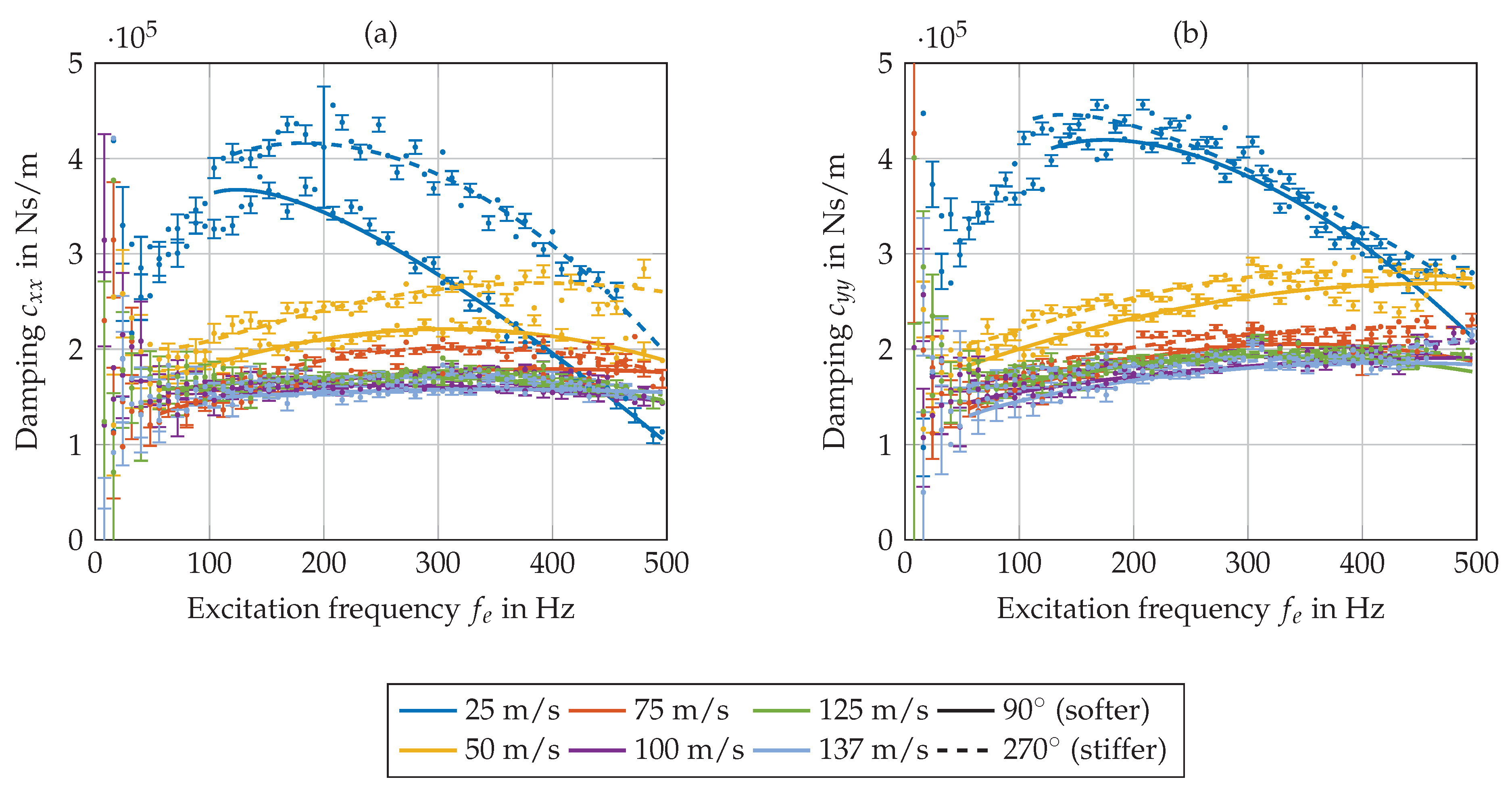
3.2.3. Impact of Pad Preload and Pivot Offset on Dynamic Bearing Coefficients

To investigate the impact of preload and pivot position on dynamic bearing coefficients, both test bearings described in Table 2 and Figure 3 are run under identical test boundary conditions. Hereby, load is directed between the pivot positions of pad 2 and 3. Figure 9 includes the main stiffness and damping coefficients in the x-direction. Generally, the main coefficients in the y-direction in Figure 10 show the same frequency-dependent tendencies and, thus, are not separately discussed. Moreover, the cross-coupling coefficients are small in the case of stiffness as well as damping and do not contribute to the discussion of the results in this paper. Therefore, a presentation of their characteristics is omitted. Figure 9 compares the results of the dynamic coefficients of both test bearings evaluated in the KC-model according to Section 2 for different frequency ratios. In general, the stiffness curves in Figure 9a–c show higher values and a higher frequency dependency of the dynamic stiffness coefficients for the bearing with center-pivoted pads and low preload. The differences are more pronounced for small loads. Concordantly, the stiffness curves display a lower increase with rising excitation frequency for the bearing with eccentric-pivoted pads and higher preload. The inflection point of stiffness to positive gradients with increasing excitation frequency is shifted to higher frequency values with decreasing bearing load. This phenomenon can be attributed to the reduction in the ratio between oil film and support stiffness with decreasing bearing load. Consequently, lightly loaded bearings with sufficient pad support stiffness tend to show the impact of the support stiffness at higher excitation frequencies than highly loaded ones. Furthermore, the impact of the excitation frequency on dynamic stiffness coefficients decreases from Figure 9a–c, similar to the results presented in Figure 7, as the evaluated frequency ratio Ω decreases due to the increasing rotating frequency.
Figure 9d–f includes the comparison of the experimentally determined dynamic damping coefficients c x x of the two test bearing configurations. In contrast to the stiffness curves, the differences in the main damping coefficients are already observable at lower excitation frequencies. The damping curves exhibit a strong frequency-dependent characteristic, especially for the lowest rotational speed in Figure 9d. In accordance with the stiffness coefficients, the measured damping shows a larger frequency dependence effect for the bearing with center-supported pads and low preload than for the bearing with off-center supported pads and larger preload. A comparison between the theoretically and experimentally determined general characteristics of the damping coefficients shows disagreement for low excitation frequencies. The theoretical investigation in Figure 4 shows almost constant damping values for low frequencies, while the measurements tend towards lower damping values with decreasing excitation. This becomes apparent particularly at high bearing loads. Together with the deviations from the theory, the measurement uncertainty also increases. Since the measurement of the imaginary part has almost constant scatter of the data points over the frequency range, the statistical uncertainty of the damping increases with decreasing frequency ratio due to the division by ω . However, similar tendencies are reported in ref. [45].

4. Conclusions

This paper investigates the impact of excitation frequency on the dynamic tilting-pad journal bearing coefficients for different rotor speeds and bearing loads. Generally, the measured results show the influence of excitation frequency on the identified coefficients, in particular with an increasing ratio between excitation and rotational frequency. This frequency dependency does not only exist for the stiffness coefficients but is also clearly observable for the damping coefficients, which is controversial in the literature so far. However, only slight frequency dependency exists in the practically highly relevant subsynchronous frequency range. Here, an approximation of the dynamic bearing behavior by frequency-independent coefficients is appropriate in wide ranges. Moreover, the reduction in bearing stiffness and damping by structural stiffness is clearly observable, and in accordance with the results of other experimental studies, a rise in bearing stiffness coefficients due to limited pivot support and pad flexibility can be observed for supersynchronous excitations.
A special emphasis in this study is given to the impact of pad preload and pivot position. The comparison of the results for the two test bearings varying with respect to these properties indicates that the dynamic coefficients of the test bearing with lower preload and centered pivot show higher dependence on excitation frequency than those of the test bearing with higher preload and eccentric pivot. However, this effect becomes predominantly noticeable for high frequency ratios, and the dynamic coefficients of both bearings generally show a similar characteristic at this frequency range. Especially at subsynchronous excitation frequencies, the differences between the dynamic coefficients of the two bearings are nearly constant, accompanied with no significant differences in their dependence on excitation frequency. The general results of the experimental identification of dynamic bearing coefficients in this study prove the tendencies of theoretical predictions reported by the authors and other researchers.

Author Contributions

T.H. and H.S. were responsible for fundraising and project management and reviewed and edited the article. P.Z. conducted the experiments, analyzed the data together with D.V., and wrote the manuscript. All authors have read and agreed to the published version of the manuscript.

Funding

This research was funded by the German Federal Ministry of Economic Affairs and Climate Action. The financial support was assigned by the Industrial Research Association (AiF e. V.) in project number IGF 20609 N. The authors also thank the expert committees of the German research associations FVV e. V. and FVA e. V. for the technical and scientific steering of this research project.

Data Availability Statement

Available on request.

Conflicts of Interest

The authors declare no conflict of interest.

Abbreviations

The following abbreviations are used in this manuscript:
Roman lettersQVolume flow ( l / min )
aAcceleration (m/s 2 ) R e * Modified Reynolds number R e * = c R R e
a v Pivot offset positionsEmpirical standard deviation
cDamping (N s/m)tStudent t distribution
dDisplacement (m)TTot. measurement time (s)
fForce (N) T i n Lube oil supply temperature (°C)
f e Excitation frequency (Hz) T i n Lube oil supply temperature (°C)
f s Synchronous frequency (Hz)uUncertainty
G i i Spectral density, auto correlated signal U Output signal, 2D
G i j Spectral density, cross correlated signal Y Input signal, 2D
HTransfer function, 1DGreek letters
H Frequency response function Ω Frequency ratio Ω = f e f s
IClean signal, 1D ω Rotation frequency (rad)
JNoisy signal, 1D α Load direction ( )
kStiffness (N/m) φ Direction of coordinate system ( )
k t Tangent support stiffness (N/m)Superscripts and subscripts
mPreload m = 1 c b c p *Conjugate complex numbers
m s Excited mass (kg)TTest
nNo. of measurements0Baseline
NTot. no. of frequenciesx,yx,y-direction
p ¯ Unit Load p ¯ = f b D (MPa)

References

  1. Reinhardt, E.; Lund, J.W. The Influence of Fluid Inertia on the Dynamic Properties of Journal Bearings. J. Lubr. Technol. 1975, 97, 159–165. [Google Scholar] [CrossRef]
  2. Parsell, J.K.; Allaire, P.E.; Barrett, L.E. Frequency Effects in Tilting-Pad Journal Bearing Dynamic Coefficients. ASLE Trans. 1983, 26, 222–227. [Google Scholar] [CrossRef]
  3. Dimond, T.W.; Younan, A.A.; Allaire, P.E.; Nicholas, J.C. Modal Frequency Response of a Four-Pad Tilting Pad Bearing With Spherical Pivots, Finite Pivot Stiffness, and Different Pad Preloads. J. Vib. Acoust. 2013, 135, 041101. [Google Scholar] [CrossRef]
  4. Cloud, C.H.; Maslen, E.H.; Barrett, L.E. Influence of tilting pad journal bearing model on rotor stability estimation. In Proceedings of the 8th IFToMM International Conference on Rotordynamic, Seoul, Republic of Korea, 12–15 September 2010; Korean Society of Mechanical Engineers: Red Hook, NY, USA, 2010. [Google Scholar]
  5. Schmied, J.; Fedorov, A.; Grigoriev, B.S. Non-synchronous tilting pad bearing characteristics. In Proceedings of the 8th IFToMM International Conference on Rotor Dynamics, Seoul, Republic of Korea, 12–15 September 2010; Curran: Red Hook, NY, USA, 2010; pp. 143–148. [Google Scholar]
  6. Yang, J.; Palazzolo, A. Three-Dimensional Thermo-Elasto-Hydrodynamic Computational Fluid Dynamics Model of a Tilting Pad Journal Bearing—Part II: Dynamic Response. J. Tribol. 2019, 141, 061703. [Google Scholar] [CrossRef]
  7. Glienicke, J. Paper 13: Experimental Investigation of the Stiffness and Damping Coefficients of Turbine Bearings and Their Application to Instability Prediction. Proc. Inst. Mech. Eng. Conf. Proc. 1966, 181, 116–129. [Google Scholar] [CrossRef]
  8. Rouvas, C.; Childs, D.W. A Parameter Identification Method for the Rotordynamic Coefficients of a High Reynolds Number Hydrostatic Bearing. J. Vib. Acoust. 1993, 115, 264–270. [Google Scholar] [CrossRef]
  9. Childs, D.W.; Hale, K. A Test Apparatus and Facility to Identify the Rotordynamic Coefficients of High-Speed Hydrostatic Bearings. ASME J. Eng. Gas Turbines Power 1994, 116, 337–343. [Google Scholar] [CrossRef]
  10. Al-Ghasem, A.; Childs, D.W. Rotordynamic Coefficients Measurements Versus Predictions for a High-Speed Flexure-Pivot Tilting-Pad Bearing (Load-Between-Pad Configuration). J. Eng. Gas Turbines Power 2006, 128, 896–906. [Google Scholar] [CrossRef]
  11. Kulhanek, C.; Childs, D.W.; Wade, J. Measured Static and Rotordynamic Coefficient Results for a Rocker-Pivot, Tilting-Pad Bearing With 50 and 60% Offsets. J. Eng. Gas Turbines Power 2012, 134, 052505. [Google Scholar] [CrossRef]
  12. Coghlan, D.; Childs, D.W. Characteristics of a Spherical Seat TPJB With Four Methods of Directed Lubrication—Part II: Rotordynamic Performance. J. Eng. Gas Turbines Power 2017, 139, 122503. [Google Scholar] [CrossRef]
  13. Suh, J.; Palazzolo, A.B. Three-Dimensional Dynamic Model of TEHD Tilting-Pad Journal Bearing—Part I: Theoretical Modeling. J. Tribol. 2015, 137, 041703. [Google Scholar] [CrossRef]
  14. Wilkes, J.C.; Childs, D.W. Improving Tilting Pad Journal Bearing Predictions—Part I: Model Development and Impact of Rotor Excited Versus Bearing Excited Impedance Coefficients. J. Eng. Gas Turbines Power 2013, 135, 012502. [Google Scholar] [CrossRef]
  15. Wilkes, J.C.; Childs, D.W. Improving Tilting-Pad Journal Bearing Predictions—Part II: Comparison of Measured and Predicted Rotor-Pad Transfer Functions for a Rocker-Pivot Tilting-Pad Journal Bearing. J. Eng. Gas Turbines Power 2013, 135, 012503. [Google Scholar] [CrossRef]
  16. Childs, D.W.; Harris, J. Static Performance Characteristics and Rotordynamic Coefficients for a Four-Pad Ball-in-Socket Tilting Pad Journal Bearing. J. Eng. Gas Turbines Power 2009, 131, 062502. [Google Scholar] [CrossRef]
  17. Wagner, L.F.; Allaire, P.E. Tilting-pad journal bearings—frequency-dependent dynamic coefficients and pivot flexibility effects. Lubricants 2022, 10, 20. [Google Scholar] [CrossRef]
  18. Wagner, L.F. Tilting-Pad Bearings—The Contact Flexibility of the Pivot. Lubricants 2023, 11, 189. [Google Scholar] [CrossRef]
  19. Dang, P.V.; Chatterton, S.; Pennacchi, P. The effect of the pivot stiffness on the performances of five-pad tilting pad bearings. Lubricants 2019, 7, 61. [Google Scholar] [CrossRef]
  20. Hagemann, T.; Schwarze, H. A Theoretical Study on Frequency Effects on Tilting-Pad Journal Bearing Dynamic Coefficients. In Proceedings of the 9th IFToMM International Conference on Rotor Dynamics, Milan, Italy, 22–25 September 2014; Pennacchi, P., Ed.; Springer: Cham, Switzerland, 2015; Volume 21, pp. 1069–1080. [Google Scholar] [CrossRef]
  21. Rodriguez, L.E.; Childs, D.W. Frequency Dependency of Measured and Predicted Rotordynamic Coefficients for a Load-On-Pad Flexible-Pivot Tilting-Pad Bearing. J. Tribol. 2006, 128, 388–395. [Google Scholar] [CrossRef]
  22. Tschoepe, D.P.; Childs, D.W. Measurements Versus Predictions for the Static and Dynamic Characteristics of a Four-Pad, Rocker-Pivot, Tilting-Pad Journal Bearing. J. Eng. Gas Turbines Power 2014, 136, 052501. [Google Scholar] [CrossRef]
  23. Hensley, J.; Childs, D.W.; Wade, J. Measurements Versus Predictions for Rotordynamic Characteristics of a Flexure Pivot-Pad Tilting Pad Bearing in an LBP Condition at Higher Unit Loads; American Society of Mechanical Engineers Digital Collection: New York, NY, USA, 2008; Volume 5, pp. 873–881. [Google Scholar] [CrossRef]
  24. Dmochowski, W. Dynamic Properties of Tilting-Pad Journal Bearings: Experimental and Theoretical Investigation of Frequency Effects due to Pivot Flexibility. J. Eng. Gas Turbines Power 2007, 129, 865–869. [Google Scholar] [CrossRef]
  25. Warner, R.E.; Soler, A.I. Stability of Rotor-Bearing Systems with Generalized Support Flexibility and Damping and Aerodynamic Cross-Coupling. J. Lubr. Technol. 1975, 97, 461–469. [Google Scholar] [CrossRef]
  26. Barrett, L.E.; Allaire, P.E.; Wilson, B. The Eigenvalue Dependence of Reduced Tilting Pad Bearing Stiffness and Damping Coefficients. Tribol. Trans. 1988, 31, 411–419. [Google Scholar] [CrossRef]
  27. Kirk, R.G.; Reedy, S.W. Evaluation of Pivot Stiffness for Typical Tilting-Pad Journal Bearing Designs. J. Vib. Acoust. 1988, 110, 165–171. [Google Scholar] [CrossRef]
  28. Lund, J.W.; Pedersen, L. The Influence of Pad Flexibility on the Dynamic Coefficients of a Tilting Pad Journal Bearing. J. Tribol. 1987, 109, 65–70. [Google Scholar] [CrossRef]
  29. Brockwell, K.; Kleinbub, D.; Dmochowski, W. Measurement and Calculation of the Dynamic Operating Characteristics of the Five Shoe, Tilting Pad Journal Bearing. Tribol. Trans. 1990, 33, 481–492. [Google Scholar] [CrossRef]
  30. Rouch, K.E. Dynamics of Pivoted-Pad Journal Bearings, Including Pad Translation and Rotation Effects. ASLE Trans. 1983, 26, 102–109. [Google Scholar] [CrossRef]
  31. Ha, H.; Yang, S. Excitation Frequency Effects on the Stiffness and Damping Coefficients of a Five-Pad Tilting Pad Journal Bearing. J. Tribol. 1999, 121, 517–522. [Google Scholar] [CrossRef]
  32. Dmochowski, W.; Brockwell, K. Dynamic Testing of the Tilting Pad Journal Bearing. Tribol. Trans. 1995, 38, 261–268. [Google Scholar] [CrossRef]
  33. Wygant, K.D.; Flack, R.D.; Barrett, L.E. Measured Dynamic Performance of a Tilting Pad Journal Bearing Over a Range of Forcing Frequencies—Part II: Dynamic Operating Conditions. Tribol. Trans. 2006, 47, 585–593. [Google Scholar] [CrossRef]
  34. Carter, C.; Childs, D.W. Measurements Versus Predictions for the Rotordynamic Characteristics of a Five-Pad Rocker-Pivot Tilting-Pad Bearing in Load-Between-Pad Configuration. J. Eng. Gas Turbines Power 2009, 131, 012507. [Google Scholar] [CrossRef]
  35. Delgado, A.; Vannini, G.; Ertas, B.; Drexel, M.; Naldi, L. Identification and Prediction of Force Coefficients in a Five-Pad and Four-Pad Tilting Pad Bearing for Load-on-Pad and Load-Between-Pad Configurations. J. Eng. Gas Turbines Power 2011, 133, 092503. [Google Scholar] [CrossRef]
  36. Childs, D.W.; Delgado, A.; Vannini, G. Tilting-Pad Bearings: Measured Frequency Characteristics of Their Rotordynamic Coefficients; Texas A&M University, Turbomachinery Laboratories: College Station, TX, USA, 2011. [Google Scholar] [CrossRef]
  37. Zemella, P.; Hagemann, T.; Pfau, B.; Schwarze, H. Identification of Dynamic Coefficients of a Five-Pad Tilting Pad Journal Bearing Up to Highest Surface Speeds. J. Eng. Gas Turbines Power 2021, 143, 081013. [Google Scholar] [CrossRef]
  38. Hagemann, T.; Blumenthal, H.; Kraft, C.; Schwarze, H. A study on energetic and hydraulic interaction of combined journal and thrust bearings. In Proceedings of the Turbo Expo: Power for Land, Sea, and Air. American Society of Mechanical Engineers, Montreal, QC, Canada, 15–19 June 2015; Volume 56765, p. V07AT31A019. [Google Scholar]
  39. Bendat, J.E.; Piersol, A. Random Data; John Wiley & Sons, Inc.: Hoboken, NJ, USA, 2010. [Google Scholar] [CrossRef]
  40. Schroeder, M. Synthesis of low-peak-factor signals and binary sequences with low autocorrelation (Corresp.). IEEE Trans. Inf. Theory 1970, 16, 85–89. [Google Scholar] [CrossRef]
  41. JCGM 100:2008; Evaluation of Measurement Data—Guide to the Expression of Uncertainty in Measurement. Joint Committee for Guides in Metrology: Geneva, Switzerland, 1993.
  42. Gerdes, R.; Fuchs, A. Nachgiebigkeit in der Segmentabstützung von Radial-Kippsegmentlagern und deren Einfluss auf die Lagerkennwerte und das Schwingungsverhalten schnelllaufender Rotor-Lager-Systeme. FVA-Forschungsheft Nr. 511, FVV/ FVA Frankfurt am Main. 1997. [Google Scholar]
  43. Allaire, P.E.; Parsell, J.K.; Barrett, L.E. A pad perturbation method for the dynamic coefficients of tilting-pad journal bearings. Wear 1981, 72, 29–44. [Google Scholar] [CrossRef]
  44. White, M.F.; Chan, S.H. The Subsynchronous Dynamic Behavior of Tilting-Pad Journal Bearings. J. Tribol. 1992, 114, 167–173. [Google Scholar] [CrossRef]
  45. Wilkes, J.C. Measured and Predicted Rotor-Pad Transfer Functions for a Rocker-Pivot Tilting-Pad Journal Bearing. Ph.D. Thesis, Texas A&M University, College Station, TX, USA, 2011. [Google Scholar]
Figure 1. Test rig main section.
Lubricants 11 00428 g001
Figure 2. Principle drawing of the investigated rotor/stator model.
Lubricants 11 00428 g002
Figure 3. Load and sensor positions of the bearing.
Lubricants 11 00428 g003
Figure 4. Theoretical impact of frequency ratio Ω on predicted KC-coefficients [20].
Lubricants 11 00428 g004
Figure 5. Measured max. bearing temperature, Q = 90 l/min, T i n = 50 °C, LBP, (a): m = 0.47 , a v = 0.6 , (b): m = 0.17 , a v = 0.5 .
Lubricants 11 00428 g005
Figure 6. Tangent support stiffness of both bearings.
Lubricants 11 00428 g006
Figure 7. Influence of support elasticity on measured dynamic stiffness coefficients k x x ( a ) and k y y ( b ). Test bearing m = 0.17 , a v = 0.5 , Q = 90 l/min, T i n = 50 C , p ¯ = 1.0 MPa, LBP.
Lubricants 11 00428 g007
Figure 8. Influence of support elasticity on measured dynamic damping coefficients c x x ( a ) and c y y ( b ). Test bearing m = 0.17 , a v = 0.5 , Q = 90 l / min , T i n = 50 C, p ¯ = 1.0 MPa , LBP.
Lubricants 11 00428 g008
Figure 9. Comparison of the measured stiffness k x x ( a c ) and damping coefficients c x x ( d f ) of the two test bearings for different max. frequency ratios Ω = f e f s . Q = 90 l / min , T i n = 50 C, LBP, α = 90 .
Lubricants 11 00428 g009
Figure 10. Comparison of the measured stiffness k y y (ac) and damping coefficients c y y (df) of the two test bearings for different max. frequency ratios Ω = f e f s . Q = 90 l / min , T i n = 50 C, LBP, α = 90 .
Lubricants 11 00428 g010
Table 1. Sensor properties.
SensorFunction PrincipleNon-Repeatability
Force Strain gauge ±10 N
Proximity probeEddy current±2 µm
Oil flow rateOvalmeter±0.3 l/min
Pad and lubricant temperatureThermocouple±1.5 K
AccelerationPiezoelectric±5.0 m/s 2
Table 2. Characteristic bearing and operating data.
ParameterValue
Geometrical PropertiesSet 1Set 2
Number of tilting pads4
Nominal diameter, mm120
Tilting-pad thickness, mm15
Bearing width, mm72
Pad arc length, 70
Pivot offset0.50.6
Radial clearance, mm(manufactured 0.102) assembled 0.107
Geometrical preload0.170.47
Static analysis parameters
Bearing load, kN0.0–27.0
Rotational speed, rpm4000–22,000
Lubricant supply temperature, C50
Lubricant flow rate, l/min90
Dynamic analysis parameters
Excitation frequency, Hz8–496
Spectral force amplitude, kN0.2
Lubricant properties
Lubricant/kinematic viscosity mm 2 /sISO VG 32/32 @ 40 C, 5.7 @ 100 C
Lubricant density, kg/m 3 865 @ 40 C
Lubricant specific heat capacity, kJ/(kg K)2.0 @ 20 C
Lubricant thermal conductivity, W/(m K)0.13
Material properties; sliding material (Babbitt)/pad and journal material (steel)
Modulus of elasticity, GPa57/210
Poisson’s ratio0.3
Heat expansion coefficient, 10 6 1/K21/11
Thermal conductivity, W/(m K)45
Disclaimer/Publisher’s Note: The statements, opinions and data contained in all publications are solely those of the individual author(s) and contributor(s) and not of MDPI and/or the editor(s). MDPI and/or the editor(s) disclaim responsibility for any injury to people or property resulting from any ideas, methods, instructions or products referred to in the content.

