Abstract
When dealing with joints and bearings, high pressures localised at the contact interface lead to residual plastic strain. The present paper combines numerical simulations and experimental tests to investigate the role of the material constitutive law in the indentation process. Numerical indentation tests between similar materials showed a good agreement with the experiments when classical material laws recovered from tensile-compressive tests on bulk samples were accounted for. On the other hand, when simulating indentation between different materials in contact, the comparison between the numerical and experimental results highlighted the limits of using classical material laws. Bilinear material laws were then derived for different steel materials (ASP 2060 PM, 100Cr6, 440C, Marval X12, and Z15 CN17-03) in contact with a ceramic indenter, leading to the correct simulation of the residual indentation profiles (error less than 5%). The proposed approach to determine suitable material laws for indentation between dissimilar materials can be further applied when dealing with applications involving contacts undergoing local plastic deformation.
1. Introduction
Several components of mechanical systems are subject to high stress–strain concentration at contact interfaces, such as wheel–rail contacts [1,2,3,4,5,6,7], contact engagement between gear teeth [8,9,10], or rolling elements [11,12]. One of the ever-present examples concerns rolling bearings, in which the mechanical elements withstand different kinds of loads and kinematics. In particular, the reduction of the bearing dimensions for lightening purposes and the increase in the transmitted power and loads introduce concerns in a reduced contact area [12,13,14,15]. Developments in numerical modelling [16,17,18] and increased computing capabilities allow for simulating the contact conditions in order to recover the contact stress and strain distributions, which are the origin of several bearing failures [12,19,20,21].
The Hertz contact theory [22] (limited to the elastic field) and recent adaptations of this theory [23] are no longer valid because of the failure of their main hypotheses, as highlighted by Wu et al. [24]. In this context, where the contact is characterised by high plastic deformations, it is necessary to use finite element models (FEMs) [25,26] or semianalytical models [27,28,29,30] in order to predict the behaviour of high-loaded elasto-plastic contacts.
Recently, many authors have dealt with the behaviour of bearings undergoing high loads and, consequently, high plastic deformations. In their work, Lacroix et al. [31] demonstrated the importance of the bearing deformation assumption, highlighting that when the deformation is neglected, an overestimation of permitted loads occurs. The work by Kogut et al. [32] showed the evolution of a frictionless contact between a rigid flat surface pressed on a sphere with elastic–plastic behaviour, in which the contact surface can withstand three different regimes (elastic, elasto-plastic, and fully plastic) as a function of a dimensionless parameter (plasticity index). Chaise et al. [18] investigated the influence of a moving load and the hardening rule (isotropic and kinematic) on the residual profile due to a sphere pressed on an elastic–plastic flat substrate. The results report that a moving load applied on a material with the kinematic law allows for leaving a deeper profile. In the case of the isotropic hardening law, a larger plasticisation is obtained when one body has only elastic behaviour and the other is characterised by the elasto-plastic material law. Studies by Brizmer et al. [33] explored the influence of Poisson’s ratio and two different friction conditions (perfect slip and full stick) when a sphere is in contact with a rigid flat sample: a larger Poisson’s ratio implies a higher contact pressure due to a less compressible material and influences the evolution of the plastic region in the stick condition, while the effects on the plastic region are negligible in the slip condition.
Nevertheless, when using finite element models for investigating contact issues [34,35,36], material laws obtained by classical stress–strain experiments on bulk samples (volumetric samples) are often introduced as material properties [37]. In fact, available mechanical properties are generally obtained from tensile or compression tests; hence, they represent the strain and stress response within the bulk of the sample. On the contrary, when dealing with high-load contacts in reduced contact areas, the plastic deformation occurs in a zone restricted and constrained to the neighbourhoods of the surfaces in contact [17], where discontinuity in material properties can occur, especially when the solids in contact have different material properties.
Consequently, the stress and strain distributions [17,38] around the contact area can be different from those obtained by tests on a continuous media. In the literature, several techniques and methods have been proposed to investigate and estimate the material properties at the contact interface: parallel rheology [39], micropipette aspiration [40], or nanotechnology tools, such as atomic force microscopy [41], which is based on conducting continuous force–distance curves [42]. In any case, parallel rheology and micropipette aspiration have been applied to cellular systems, rather than to solid materials. On the other hand, nanotechnology tools, such as raw AFM (Atomic Force Microscopy) analysis, are time-consuming techniques and relatively more expensive with respect to classical tensile or indentation tests for metallic materials. In this context, the need to define material laws representative of the material response under indentation solicitation arises, providing insights for simulations of several industrial applications. Hence, this work focuses on the analysis of the elastic–plastic behaviour of metallic materials under indentation loads imposed by indenters of either the same or a different (ceramic) material.
2. Indentation Analysis: Materials and Method
2.1. General Approach
First, numerical models representing the indentation process in both 3D and 2D are presented, validating the results from the 2D model by comparison with results from the 3D model. Second, the residual profiles obtained by the simulations with stress–strain laws coming from bulk tests are compared with experimental indentation tests when a ceramic indenter is loaded on a metallic surface. The results highlighted the need to consider different material laws to match the experimental residual plastic profiles when the indenter material is different from the indented one. Consequently, starting from a simple bilinear elasto-plastic material law defined by a reduced number of parameters (elastic modulus, yield stress, and tangent modulus), a parametrical analysis is performed. For each different metallic material, the corresponding elasto-plastic law parameters are identified to simulate the effective residual plastic profile obtained by the ceramic indenter. Finally, the comparison of experimental and numerical results obtained by the ceramic indenter with the ones obtained by an indenter of the same metallic material is performed to highlight the effect of the material discontinuity at the contact on the strain and stress distribution.
2.2. Geometry and Boundary Conditions
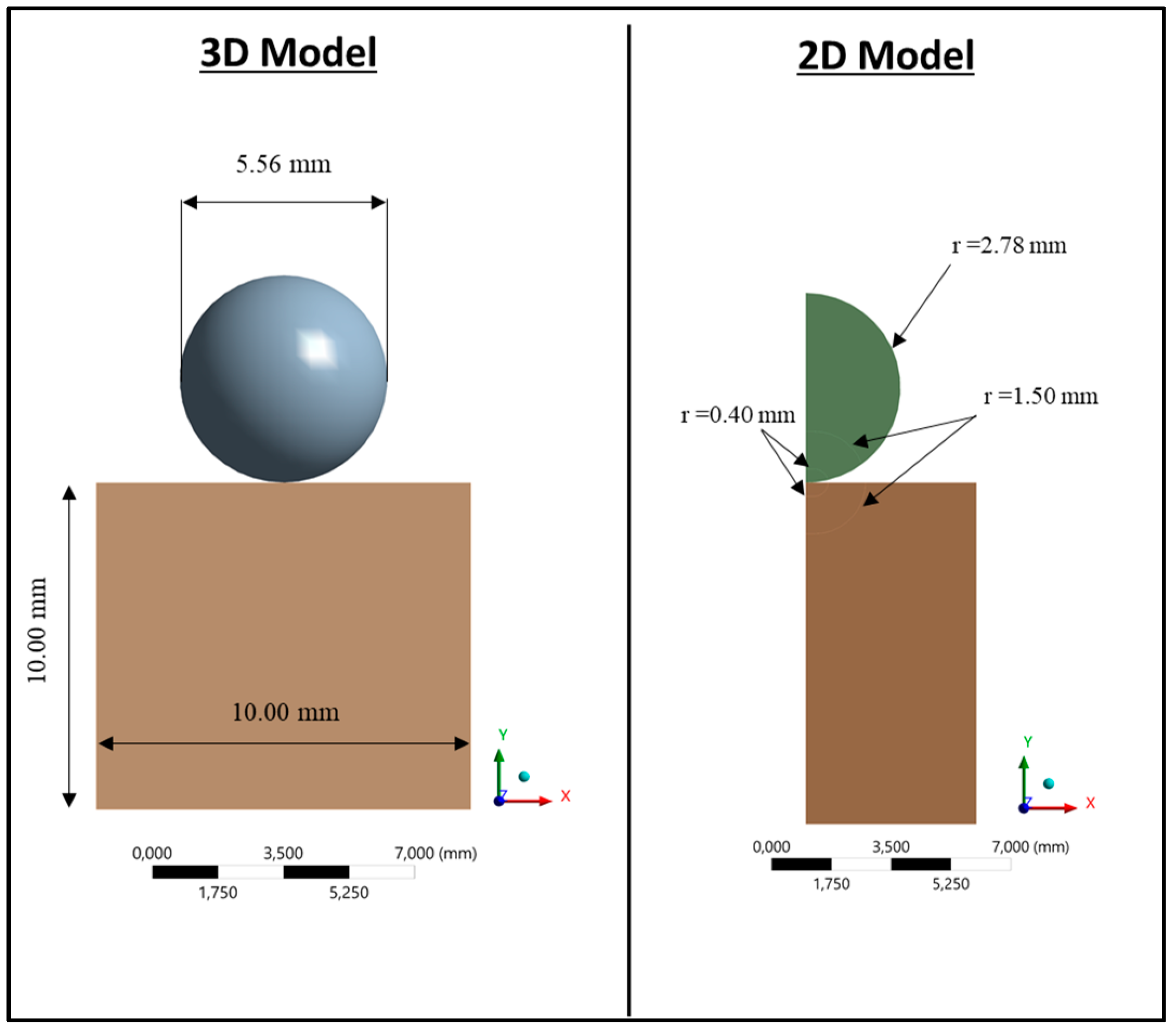
Both 3D and 2D axisymmetric models were developed using Ansys software to simulate experimental indentation tests. The geometry of the model (Figure 1) comprised a sphere (representing the indenter) and a cylindrical sample (representing the indented material sample). The sphere diameter was equal to 5.56 mm, while the diameter of the base and the height of the cylindrical sample were equal to 10.00 mm. The indenter was clamped in a support during the indentation experimental tests. Consequently, the spherical sector of the sphere surface, which was clamped into the support, was constrained along the X- and Z-axes in the model, while a displacement was imposed along the Y-axis to simulate the experimental indentation procedure for 3 different loads: 150, 500, and 2200 N. The lower base of the cylindrical sample was constrained with a plane constraint to represent the experimental boundary condition where the sample lies over the indentation table. The 2D axisymmetric model and the 3D model had equivalent boundary conditions. To retrieve the residual indentation profile, the indenter was first moved against the sample both experimentally and numerically to apply the indentation load and was subsequently removed.

Figure 1.
3D (left) and 2D axisymmetric (right) models of the indentation test.
The indentation tests were carried out using an hydraulic traction-compression machine with a capacity of 10 kN. Once the indentation test was carried out, a measurement of the residual indentation profile was made for the different tested materials at each tested load. The profile measurements were performed using a SURFASCAN 2D profilometer (SOMICRONIC, Saint André de Corcy, 01390, France) equipped with an ST 178 sensor with a radius of 0.002 mm and a pyramidal angle of 90°. For each material and load configuration, at least 4 measurements were performed. Before performing each indentation test, a grinding process was applied to the indentation profile, ensuring a roughness parameter Ra in the range 0.8–1.2 µm. Five different materials belonging to different material families were tested: ASP 2060 PM, 100Cr6, 440C, Marval X12, and Z15 CN17-03.
- ASP 2060 PM is a tungsten-molybdenum-vanadium-cobalt speed steel made according to powder metallurgy;
- 100Cr6 is a common low-alloyed chromium steel;
- 440C is a martensitic stainless steel;
- Marval X12 is a precipitation-hardening martensitic stainless steel;
- Z15 CN17-03 is a ferritic-martensitic stainless steel, subjected to a carburising heat treatment.
Their hardness values, based on the Rockwell scale, were measured and equal to 67, 63, 58, 45 and 58, respectively. Their mechanical properties (elastic modulus, yield stress, ultimate stress, elongation at break, and others) were found from the data sheet recovered from the tensile or compression test [43]. The hardness was used as a leading criterion to select the mechanical properties from the different data sheets found for the same material. Table 1 shows the material properties used for the indentation simulations. It should be noted that not all the found material hardness values matched exactly with the measured ones; hence, the reliability of these data should be considered with caution. In any case, the scattering between material properties coming from bulk tests was not relevant to the obtained results.

Table 1.
Mechanical bulk properties from the tensile or compression tests.
2.3. Validation of the 2D Model
A preliminary mesh convergence analysis was performed on the 3D model by varying the element sizes in the refined area at the contact interface; different element sizes were used for the sample surface: 0.100, 0.050, 0.010, and 0.001 mm. The indenter elements were set to 0.200, 0.060, 0.020, and 0.002 mm, respectively. The percentage error between the finest and the coarsest mesh, evaluated in terms of the directional deformation along Y, the equivalent von Mises stress, and the maximum shear stress, was lower than 2%. The element size of 0.010 mm for the sample was then chosen for the numerical simulations to both save computational time and have a smooth stress and strain distribution at the contact interface. The 2D axisymmetric model was then validated by comparing the results with those obtained from the 3D model; the aim was to ensure the reliability of the 2D axisymmetric model to preserve computational effort for the parametrical analyses. The verification of the reliability of the 2D axisymmetric model was needed because of the tangential components of the contact forces; it is not ensured that forces are only radial, since circumferential components can occur as well and affect the axial symmetry of the loads and results. The mesh convergence analysis allowed defining the following contact element dimensions for the two solids in contact: 0.020 mm on the indenter and 0.010 mm on the sample. The Lagrange multiplier method was imposed at the contact interface.
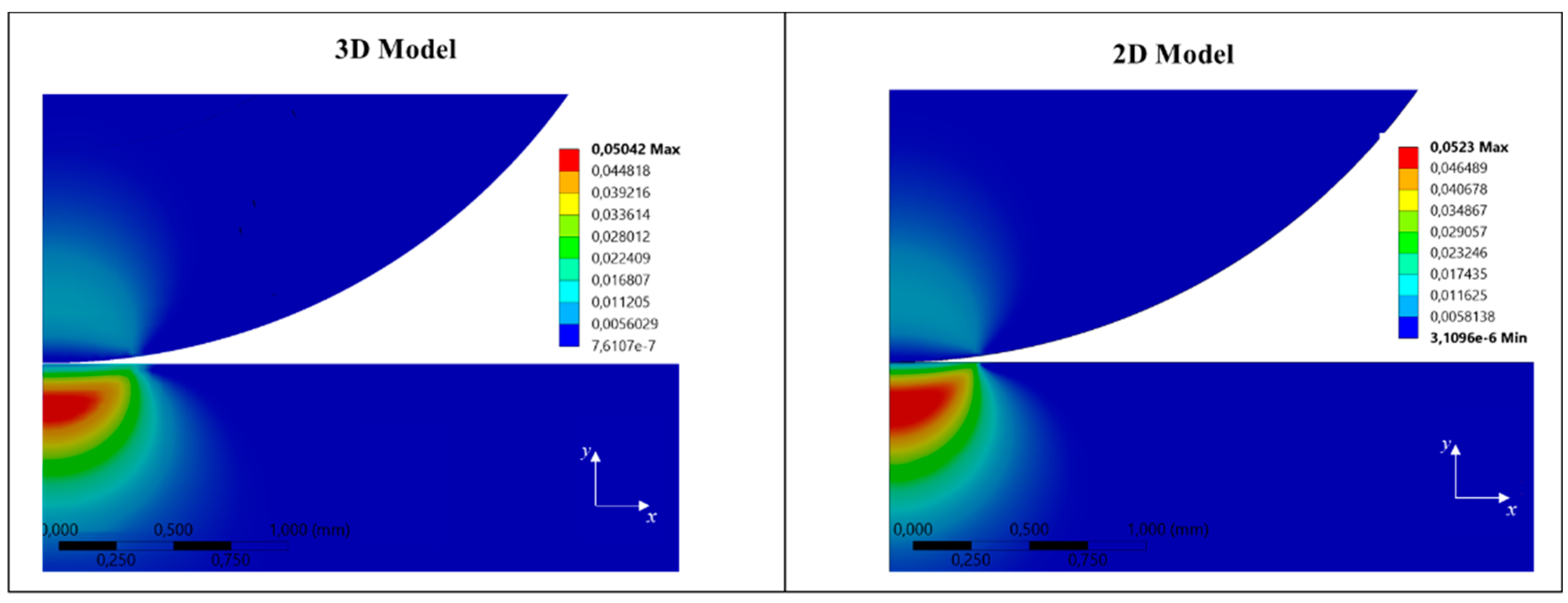
The equivalent (von Mises) stress, the maximum shear stress, the deformation along the Y-axis, the equivalent plastic strain, the contact pressure distribution, and the residual indentation profiles were used to compare the results. The numerical validation of the 2D axisymmetric model was carried out by comparing results obtained with 150 and 2200 N loads. As an example, Figure 2 shows the equivalent total strain distribution obtained with the 3D and 2D models, respectively, for a load of 2200 N. A good agreement, in terms of maximum value and strain distribution for both the sphere and the sample, was achieved.
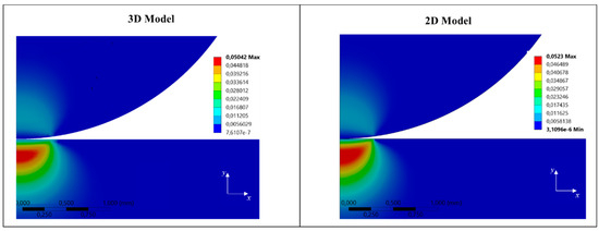
Figure 2.
Comparison of the equivalent total strain distribution obtained with the 3D (left) and 2D axisymmetric (right) models for an indentation load of 2200 N.
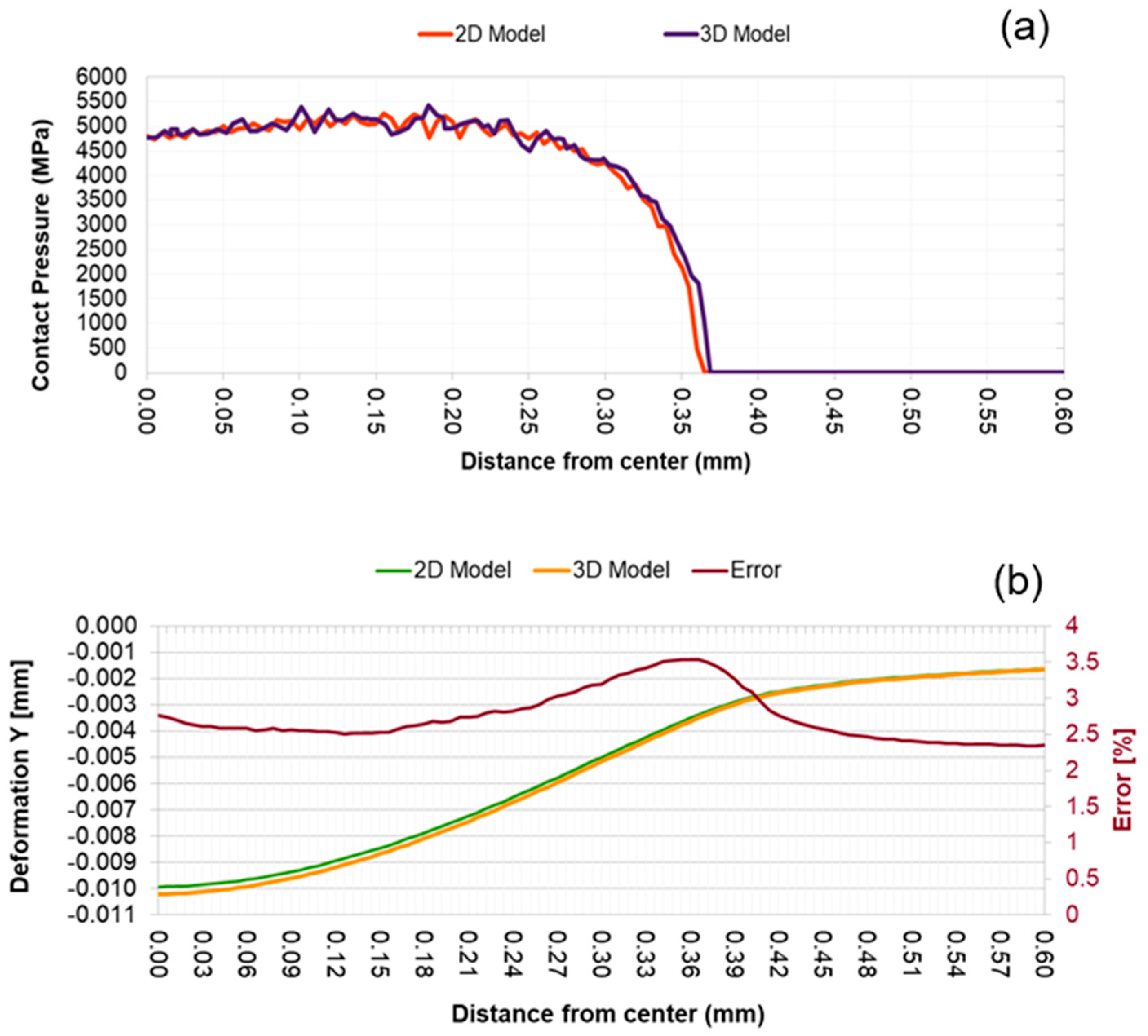
Figure 3a and Figure 3b show, respectively, the comparison of the contact pressure distributions when a load of 2200 N was applied and the comparison of the residual indentation profiles calculated at the end of the unloading phase, together with the percentage error. The results indicated that under the worst loading case, the contact pressure distribution and the residual indentation profiles coincided; the percentage error stayed below 3.5%, allowing for validating the 2D axisymmetric model. For the presented analysis, a friction coefficient of 0.3 was applied at the contact. Nevertheless, the influence of the friction coefficient on both the 3D and 2D axisymmetric models was analysed in the 0.05–0.8 range, and the results showed a negligible effect of the variation of the friction coefficient.

Figure 3.
(a) Comparison of the contact pressure distribution obtained by the 3D (left) and 2D axisymmetric (right) model when an indentation load of 2200 N is applied; (b) comparison of the residual indentation profile and the percentage error.
2.4. Elasto-Plastic Bulk Law vs. Experimental Indentation with Ceramic Indenter
For the numerical indentation tests, the mechanical properties are described in Table 1 and were obtained by tensile–compression mechanical tests on the bulk of the material. In the following, the elastic–plastic material law obtained by the tensile and compression tests will be referred as the “bulk material law”.
The introduction of the stress–strain curves obtained by such material properties for the simulation of the indentation tests provided the residual indentation depths shown in Table 2, which reports both the numerical and experimental residual indentation depths together with the percentage error.
Table 2.
Residual indentation depths from experimental data and numerical analyses with stress–strain curves recovered by tensile or compression tests. Standard deviation (SD) is reported for the experimental results.
It can be observed that, for the tested materials, the relative error between the results from experimental tests and those from the numerical simulations ranged between 2.5% and 89%. The reason for the large difference between the numerical and experimental results is mainly attributed to the nonappropriateness of the used stress–strain curves, which were derived from classical mechanical tests where the deformation process was applied to a continuum media (sample bulk). In contrast, the indentation tests involved the overall deformation of two solids in contact with the discontinuity of the material properties at the contact interface. Superficial properties or property gradients, concentration of local high stresses and gradients, and discontinuity on the stress distribution at the contact interface were not accounted for by the material bulk properties.
For this reason, a different stress–strain curve, able to correctly reproduce the experimental indentation process, needs to be developed to correctly simulate the superficial contact stress distribution and, consequently, the residual indentation profiles.
3. Bilinear Material Law for Ceramic on Steel Indentation
3.1. Parametrical Analysis
As a first step toward the definition of a reliable stress–strain material law for ceramic on steel indentation, a parametrical analysis was developed to investigate how the indentation profiles varied with respect to the variations of the main law variables and to identify the most influential parameters on the indentation process. A reference material, the 100Cr6 steel, with the stress–strain bulk material law in Figure 4, was accounted for.
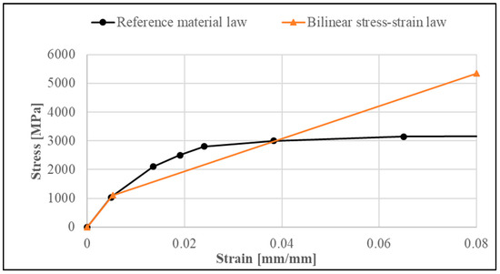
Figure 4.
Stress–strain material law (black curve) of the reference material with Young’s modulus of 210 GPa and yield stress of 1034 MPa. Bilinear material law (orange curve) with Young’s modulus of 210 GPa, yield stress of 1100 MPa, and tangent modulus of 85 GPa.
The input parameters considered were the elastic modulus (E), the yield stress (σy), and the tangent modulus (Et), while the residual profile depth and width were the considered output parameters. A load of 2200 N was applied and then removed to analyse the indentation profile due to the residual plastic strain. The parametrical analysis was carried out by varying the elastic modulus, yield stress, and tangent modulus by ±20%. The analysis was performed by modifying the reference bilinear stress–strain response (orange curve) in Figure 4. The bilinear isotropic hardening model is defined by the following equations:
where σy, E, and Et represent the yield stress, Young’s modulus, and the tangent modulus, respectively.
Bilinear stress–strain curves were adopted in this work to reduce the number of parameters and to provide easily implementable material laws.
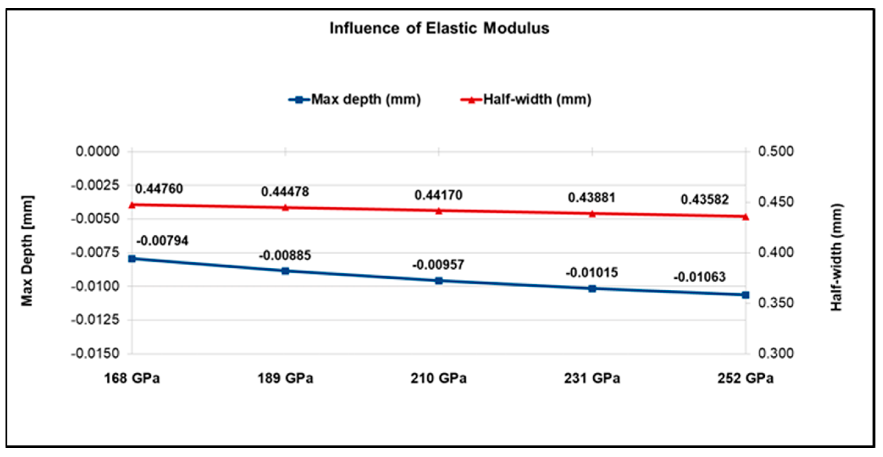
3.1.1. Influence of the Elastic Modulus
The elastic modulus had a slight influence on the variation in the residual depth and width (Figure 5). A larger elastic modulus value leaves a deeper profile because it tends to concentrate the stress field and increase the local plastic deformation, while the width tends to decrease with the increase in the material stiffness.
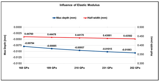
Figure 5.
Influence of the elastic modulus on the indentation profile for a load of 2200 N.
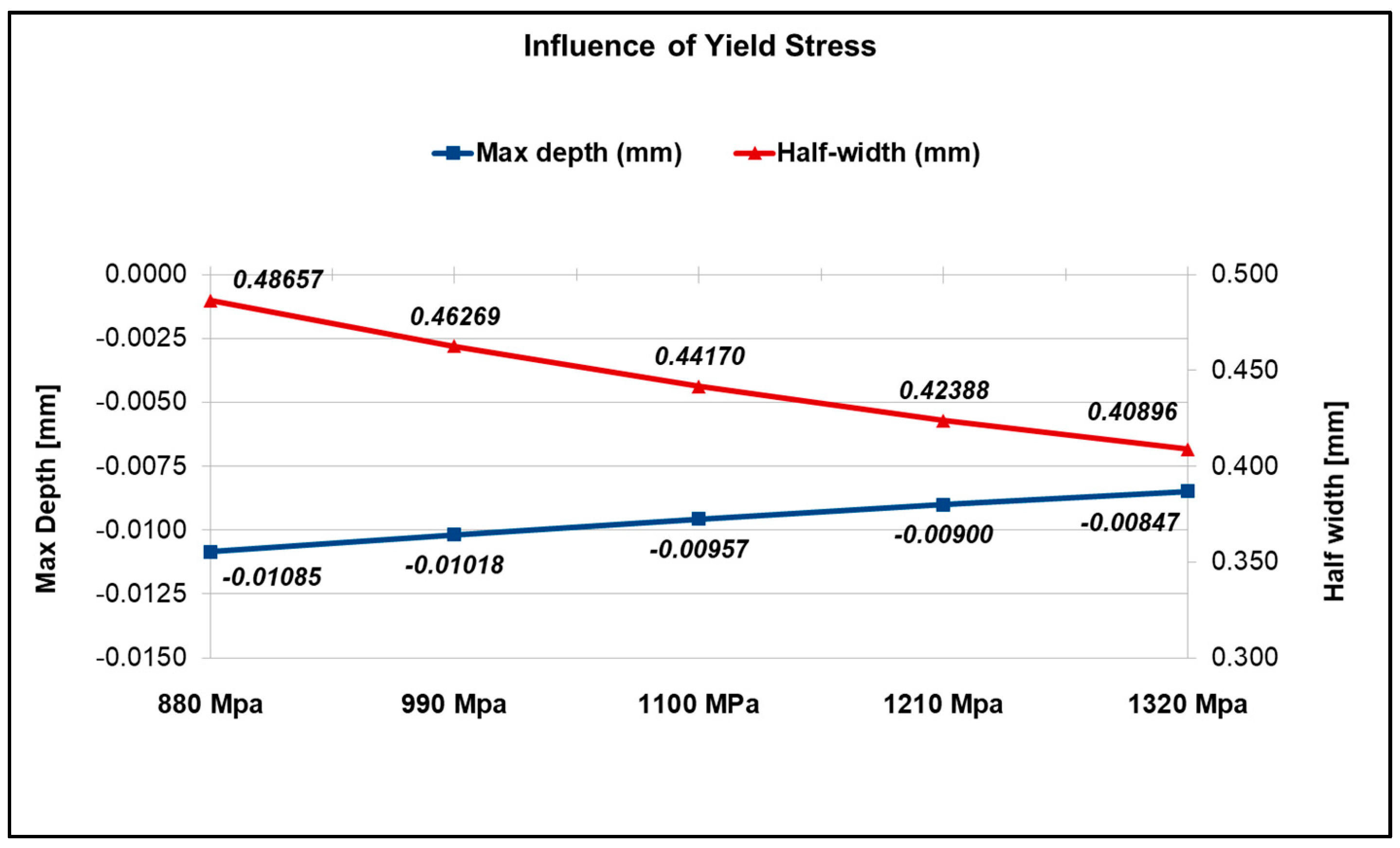
3.1.2. Influence of the Yield Stress
The yield stress had a large influence on the variation in the indentation residual profiles (Figure 6). A quasi-linear decreasing trend of the depth, with the increase in the yield stress, can be observed. This larger influence was due to the close relationship between yield stress and the plasticisation of the material.

Figure 6.
Influence of yield stress on the indentation profile for a load of 2200 N.
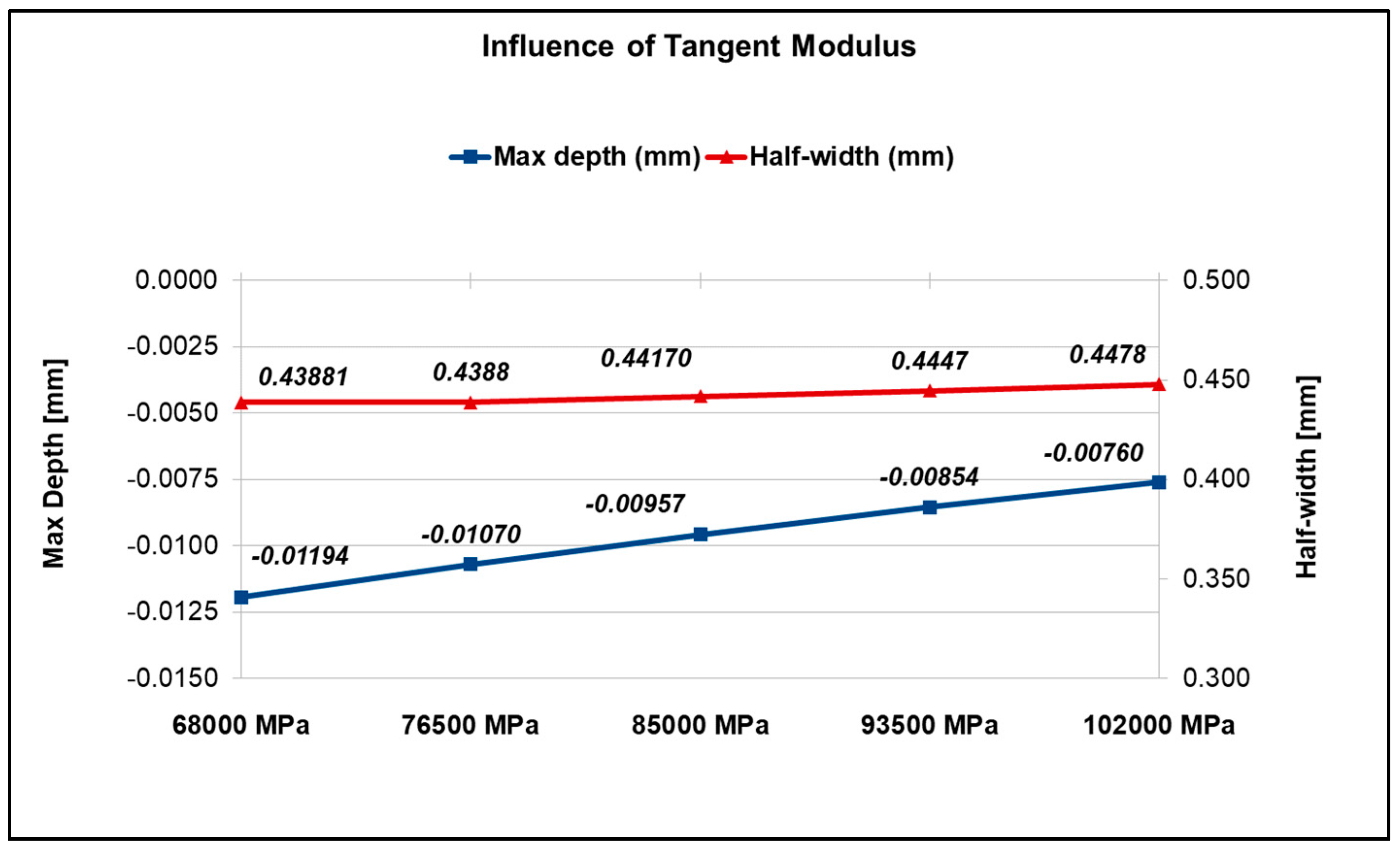
3.1.3. Influence of the Tangent Modulus
The tangent modulus had a large influence on the variation in the indentation residual profiles (Figure 7). In fact, this parameter acted directly on the plastic behaviour and the material hardening. It is possible that a decrease in the tangent modulus allows for obtaining deeper and slightly larger profiles.
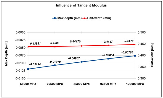
Figure 7.
Influence of the tangent modulus on the indentation profile for a load of 2200 N.
3.2. Bilinear Material Laws Identification
Once the sensitivity analysis was completed, the stress–strain curves that allowed obtaining residual indentations in agreement with the experimental data were retrieved. The experimental residual depths were considered to be the reference for the research into more suitable bilinear material curves to input in the FEM software.
The optimal material law for each material was searched with an iterative approach, accounting for the sensitivity analysis presented above. Because of the negligible effect on the residual indentation profile, the elastic modulus was fixed, as provided by the tensile and compression tests on the bulk. The bilinear stress–strain curve was then completely defined by the optimisation of the two other parameters, the yield stress σy and the tangent modulus Et, which are the degree of freedom for optimisation. Table 3 shows the mechanical properties found for the bilinear stress–strain curves of the tested materials under indentation with the ceramic indenter.
Table 3.
Mechanical properties of the bilinear stress–strain curves for the tested materials indented by ceramic indenter.
The residual depths, obtained numerically by the identified material laws, are reported in Table 4 and compared with the experimental results. The percentage error between the numerical and experimental residual depths was always less than 5%, except for the lowest load (150 N), due to the measurement uncertainty caused by small indentation depths, which were comparable with the surface roughness. Additionally, the residual indentation depth for the 100Cr6 could not be recovered experimentally because it was comparable with the surface roughness. Except for the measurement incertitude at low loads, the defined bimaterial laws allowed a low scattering (less than 5%) between the numerical and experimental residual indentation depths.
Table 4.
Experimental and numerical residual depths obtained using the bilinear stress–strain curve reported in Table 3. Standard deviation (SD) is reported for the experimental results.
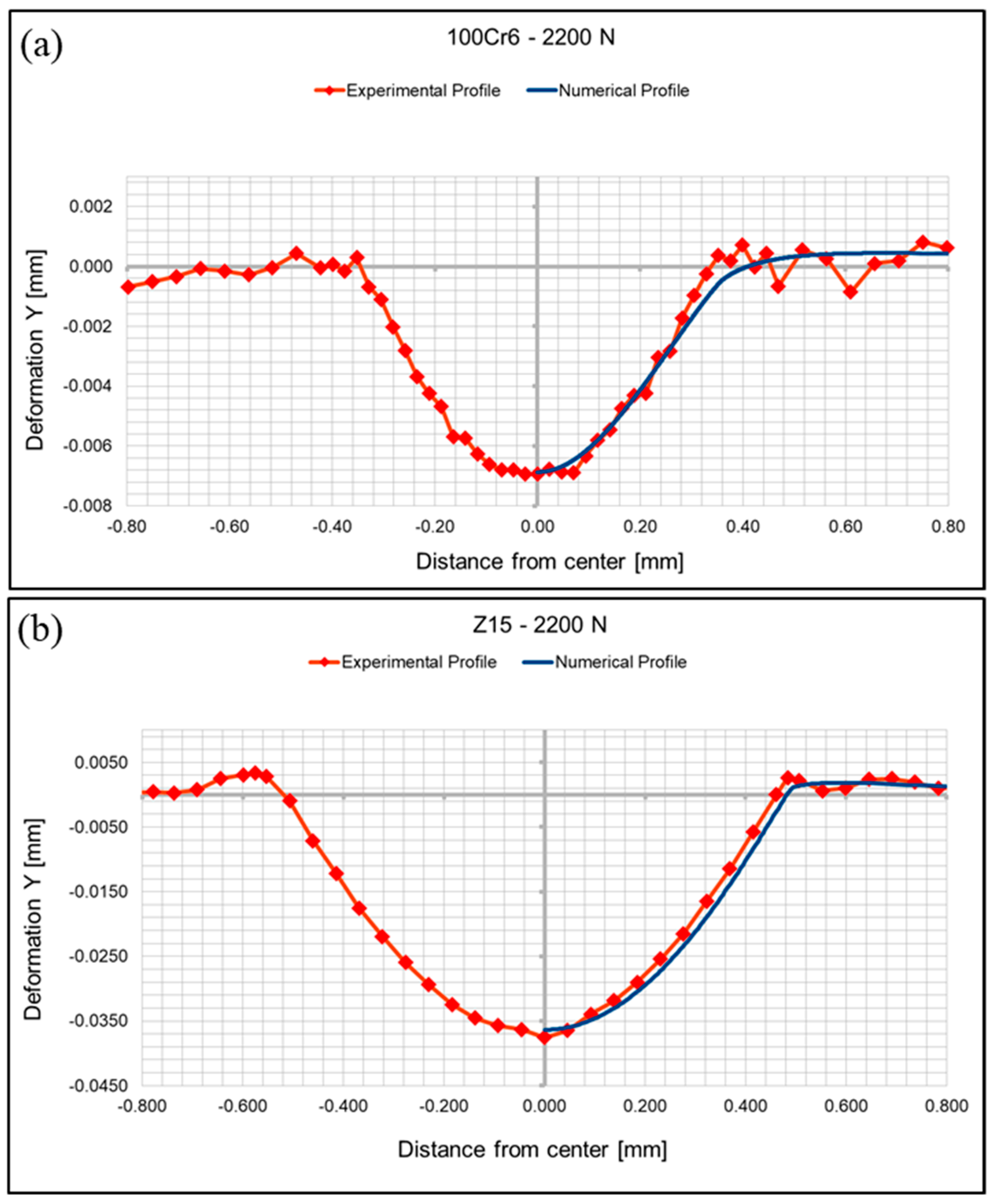
The numerical indentation profiles were then compared with the residual indentation profiles measured experimentally. The numerical and experimental indentation profiles matched in both depth and form for the different tested materials and loads. As an example, Figure 8 shows the comparison of the experimental and numerical residual indentation profiles for the 100Cr6 and the Z15 materials for a 2200 N indentation load (ASP 2060, 440C and Marval materials results are reported in the Supplementary Materials).
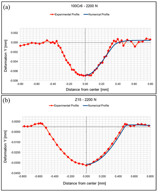
Figure 8.
Numerical and experimental residual indentation profiles for the 100Cr6 material (a) and the Z15 material (b) under an indentation load of 2200 N.
4. Effect of the Indenter Material
This section describes the experimental and numerical analyses that were carried out to investigate the elasto-plastic material law most suitable for the indentation process when the indenter is made of a harder material than the indented solid (ceramic, Si3N4) or the same material (steel, 100Cr6) as the indented solid.
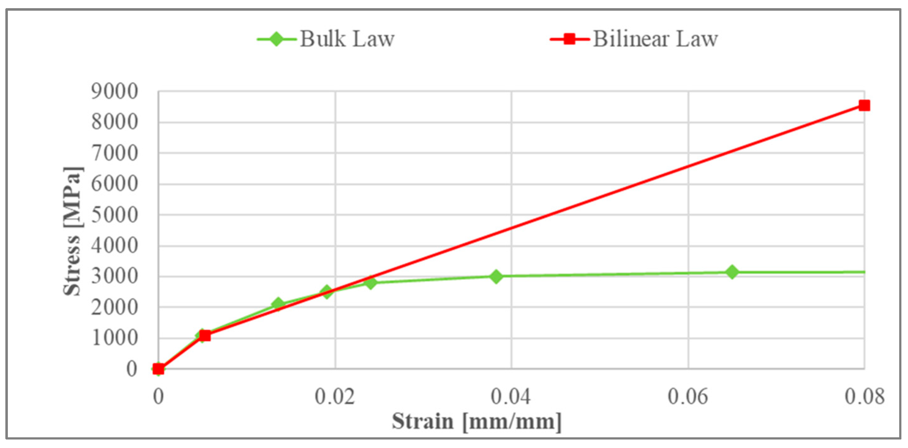
To investigate the material response within a larger range of plastic strain, the numerical and experimental tests were performed as a function of three different loads: 1500, 2500, and 3600 N. The numerical model used for simulating the elasto-plastic indentation is the same as that described in Section 2. The stress–strain material laws used in the numerical simulations are reported in Figure 9. For the bilinear material law, Young’s modulus, the yield strength, and tangent modulus are those reported in Table 3 for the 100Cr6 material by the parametrical analysis (Section 3.2).
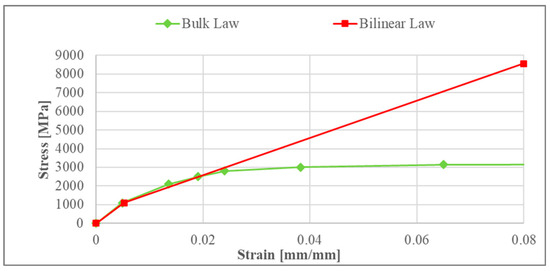
Figure 9.
Bilinear material law (red curve) vs. bulk stress–strain curve (green curve) for the 100Cr6 material.
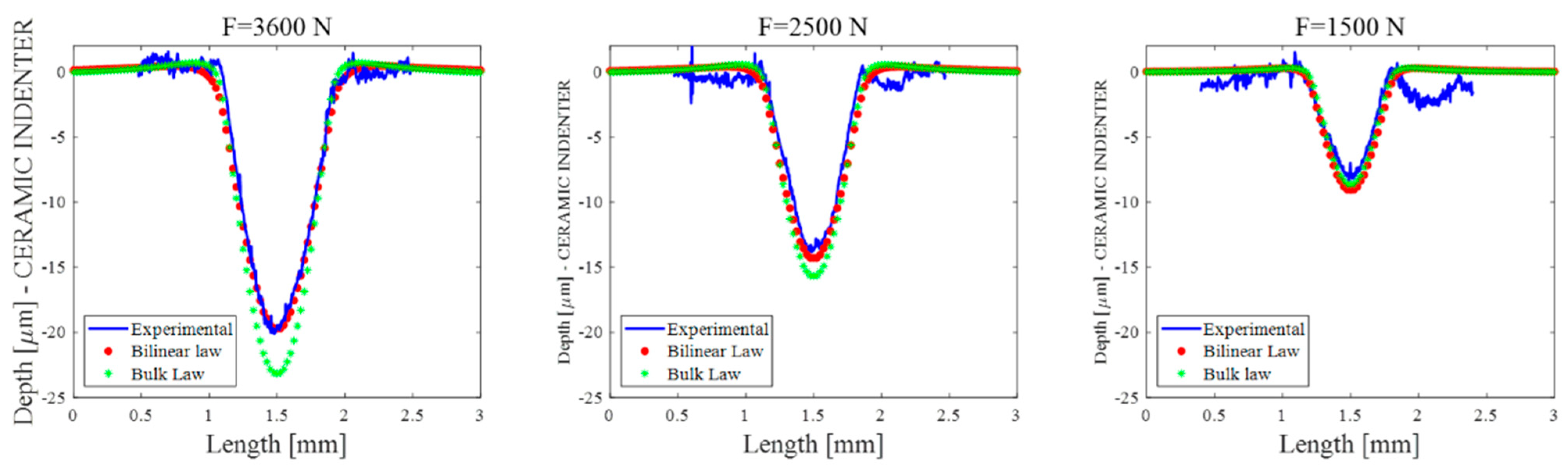
4.1. Ceramic on Steel Indentation Tests
Figure 10 shows the indentation results in terms of the residual indentation profiles obtained considering the ceramic indenter (Si3N4) pressed against the steel sample (100Cr6). The blue curve represents the experimental indention profile, while the red and green curves represent the numerical indentation profiles recovered using the bilinear material law and the bulk material law, respectively. The results in the figure highlight the consistency between the experiments and numerical results obtained using the bilinear law, confirming the representativeness of the bilinear law for larger plastic fields. On the other hand, the residual indentation depths recovered using the bulk law confirmed the overestimated values for the higher loads obtained in the previous section.
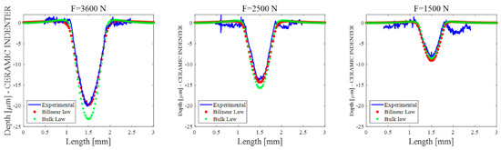
Figure 10.
Experimental and numerical residual depths for the ceramic indenter on the 100Cr6 sample (bimaterial interface).
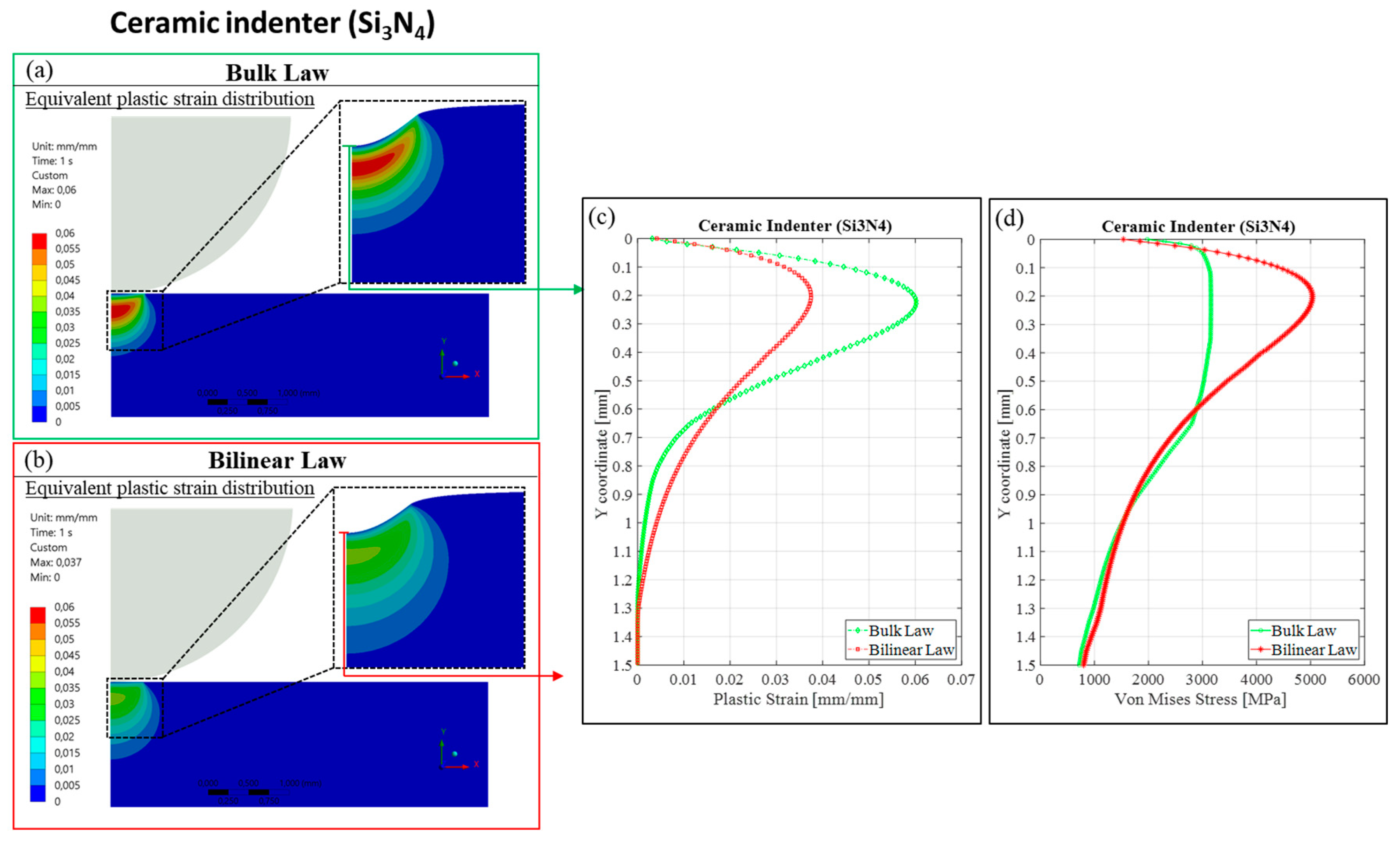
The residual depth overestimation derived from the bulk material law was investigated by looking at the strain and stress distributions recovered numerically while the maximum indentation load (3600 N) was applied. Figure 11 shows the numerical results obtained with the two material laws: the bulk law (a) and the bilinear law (b). The equivalent plastic strain distribution highlights a different plastic behaviour within the material substrate for the two analysed laws. The steel sample showed an overall similar distribution in term of the plastic strain, but with higher values in the case of the bulk material law with respect to the bilinear law, as highlighted by the profiles in Figure 11c (plastic strain as a function of the depth coordinate computed at the middle of the contact surface). Moreover, looking at the stress distributions in Figure 11d, the bulk law results confirmed the excessive yielding of the material when the stress exceeded the value of the yield strength for the bulk law, highlighting an almost perfectly plastic behaviour. On the other hand, the bilinear law allowed the sample to be more resilient in terms of deformation, thanks to the hardening behaviour in the larger plastic ranges. Therefore, when the indentation process occurs between dissimilar materials (ceramic indenter and 100Cr6 sample), a discontinuity in the stress–strain fields occurs at the interface, leading to a nonuniform and localised stress distribution.
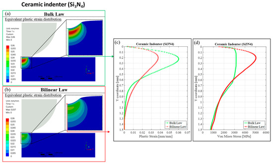
Figure 11.
Equivalent plastic strain distribution for bulk (a) and bilinear (b) material laws. (c) Plastic strain profiles as a function of depth recovered at the centre of the contact. (d) Equivalent von Mises stress profiles as a function of depth recovered at the centre of the contact. All the data in the figure are recovered for an indentation load of 3600 N with the ceramic indenter.
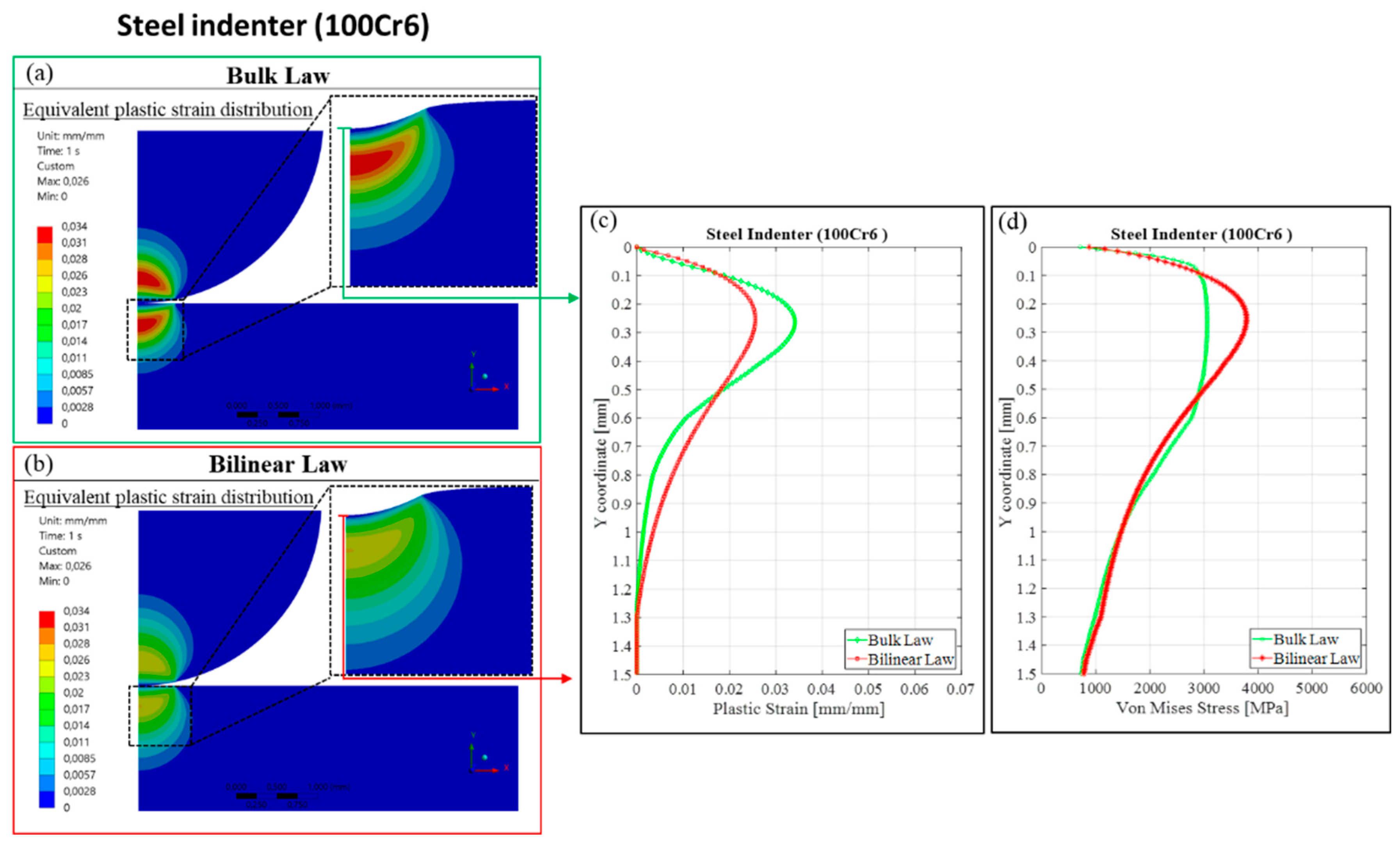
4.2. Steel-on-Steel Indentation Tests
To investigate the bi-material effect in the indentation process, the numerical and experimental indentation tests were then performed using the same material (100Cr6) for both the indenter and the indented solid. The experimental and numerical results, in terms of residual depths, are reported in Figure 12. In this case, the bilinear material law overestimated the residual indentation depth for all the tested loads, while the bulk material law exhibited consistency with the experiments, contrary to what happened in the case of the ceramic on steel indentation.
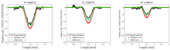
Figure 12.
Experimental and numerical residual depths for the 100Cr6 indenter on the 100Cr6 sample (same material interface).
Moreover, when considering the plastic strain distribution on the steel indenter (not present on the ceramic indenter in Figure 11 because of the ceramic higher yield stress), the numerical indentation results obtained with the same materials showed a symmetric distribution (between the indenter and indented solid) of the plastic strain with respect to the contact interface (Figure 13). In this case, even if the plastic strain reached the maximum value in the case of the bulk law, the residual indentation depth for the bulk law would be lower than the bilinear law and in agreement with the experimental indentation results, as shown in Figure 12.

Figure 13.
Equivalent plastic strain distribution for bulk (a) and bilinear (b) material laws. (c) Plastic strain profiles as a function of depth recovered at the centre of the contact. (d) Equivalent von Mises stress profiles as a function of depth recovered at the centre of the contact. All the data in the figure are recovered for the indentation load of 3600 N considering the steel (100Cr6) indenter.
In the case of indentation with the same material (100Cr6 on 100Cr6), the plastic region occurred both in the sphere and in the indented sample. The continuity of the mechanical properties on the two sides of the contact interface can explain the consistency between the experiments when using a classical bulk law obtained experimentally by tensile and compression tests on a continuum bulk sample of the tested material. In fact, the stress and strain distributions obtained when performing compression tests on a bulk sample are representative of the ones obtained in the case of contact indentation when the indenter and indented solid had the same material properties. On the contrary, a harder indenter modifies the strain and stress distributions in the surface and subsurface, and the elasto-plastic material law obtained by tensile and compression tests is no more reliable.
5. Conclusions
In this work, numerical and experimental analyses of an indentation process were performed to identify elasto-plastic material laws able to predict the real indentation responses of different steel materials (ASP 2060 PM, 100Cr6, 440C, Marval X12, and Z15 CN17-03). While bulk material laws (from tensile–compression tests) were shown to be reliable in simulating residual indentation between solids of the same material (errors lower than 5% for 100Cr6), they were inadequate for simulating indentation between dissimilar materials (up to 37% error in the simulated residual indentation profile). Consequently, a combined numerical and experimental approach was defined to identify bilinear elasto-plastic material laws able to correctly simulate the indentation process between dissimilar materials. A parametrical analysis allowed us to define the parameter of the material law for each tested material, obtaining simulation results with a percentage error lower than 5% in the residual indentation profile. On the one hand, the results from this work highlighted the unsuitability of using the material laws obtained by tensile–compression tests on bulk samples when simulating plastic contacts between dissimilar materials. On the other hand, a practical approach to obtain simplified constitutive laws for simulating indentation between dissimilar materials is proposed here. The findings of this work can be useful for industrial applications characterised by contact interfaces with localised high-contact pressure and contact plastic strain (gears, bearings, coatings, composite materials, etc.). As a future step, the proposed approach will be applied to other families of materials and more complex constitutive laws to extend the obtained results to a larger variety of applications.
Supplementary Materials
The following supporting information can be downloaded at: https://www.mdpi.com/article/10.3390/lubricants11100438/s1, Figure S1: Numerical and experimental residual indentation profiles for the 440C material under an indentation load of 2200 N; Figure S2: Numerical and experimental residual indentation profiles for the ASP 2060 PM material under an indentation load of 2200 N; Figure S3: Numerical and experimental residual indentation profiles for the Marval X12 material under an indentation load of 2200 N.
Author Contributions
Conceptualisation, D.T. and F.M.; methodology, D.T. and F.M.; software, D.T. and F.P.; validation, D.T., F.M., G.L.J., A.M. and Y.M.; formal analysis, F.P., D.T., F.M., A.M., F.P. and Y.M.; investigation, F.P., D.T., G.L.J., A.M., F.M. and Y.M.; resources, F.P., D.T., G.L.J., A.M., F.M. and Y.M.; data curation, D.T. and F.M.; writing—original draft preparation, F.P., D.T. and F.M.; writing—review and editing, F.P., D.T., G.L.J., A.M., F.M. and Y.M.; visualisation, F.P., D.T., G.L.J., A.M., F.M. and Y.M.; supervision, D.T., F.M., G.L.J. and A.M.; project administration, F.M., G.L.J., A.M. and Y.M.; funding acquisition, F.M., A.M. and Y.M. All authors have read and agreed to the published version of the manuscript.
Funding
This research received no external funding.
Data Availability Statement
The data presented in this study are available on request from the corresponding author.
Conflicts of Interest
The authors Alexandre Mondelin, Gwenolè Le Jeune, and Yves Mahéo were on the staff of SKF Aerospace. In the past, Francesco Massi received funding for research on different topics by SKF Aerospace. Nevertheless, the research results reported in the paper are about fundamental research and have no direct commercial or marketing outcomes. For this reason, no direct conflicts of interest are declared by these authors. The remaining authors declare that the research was conducted in the absence of any commercial or financial relationships that could be construed as potential conflicts of interest.
References
- Nejad, R.M.; Shariati, M.; Farhangdoost, K. Effect of wear on rolling contact fatigue crack growth in rails. Tribol. Int. 2016, 94, 118–125. [Google Scholar] [CrossRef]
- Daves, W.; Kubin, W.; Scheriau, S.; Pletz, M. A finite element model to simulate the physical mechanisms of wear and crack initiation in wheel/rail contact. Wear 2016, 366, 78–83. [Google Scholar] [CrossRef]
- Piotrowski, J.; Kik, W. A simplified model of wheel/rail contact mechanics for non-Hertzian problems and its application in rail vehicle dynamic simulations. Veh. Syst. Dyn. 2008, 46, 27–48. [Google Scholar] [CrossRef]
- Duan, F.; Pozzolini, C.; Saulot, A.; Berthier, Y. An improved 2D fem model for straight track corrugation using the mass redistribution method. Mech. Ind. 2017, 18, 310. [Google Scholar] [CrossRef]
- Wang, Q.; Wang, Z.; Mo, J.; Zhang, L. Nonlinear behaviors of the disc brake system under the effect of wheel−rail adhesion. Tribol. Int. 2021, 165, 107263. [Google Scholar] [CrossRef]
- Mann, R.; Magnier, V.; Brunel, J.; Dufrénoy, P.; Henrion, M.; Guillet-Revol, E. Thermomechanical characterization of high-speed train braking materials to improve models: Numerical validation via a comparison with an experimental braking test. Tribol. Int. 2020, 156, 106818. [Google Scholar] [CrossRef]
- Muflikhun, M.A.; Adyudya, M.; Rahman, N.F.; Sentanuhady, J.; Raghu, S.N.V. Comprehensive analysis and economic study of railway brake failure from metal-based and composites-based materials. Forces Mech. 2023, 12, 100223. [Google Scholar] [CrossRef]
- Hou, X.; Fang, Z.; Zhang, X. Static contact analysis of spiral bevel gear based on modified VFIFE (vector form intrinsic finite element) method. Appl. Math. Model. 2018, 60, 192–207. [Google Scholar] [CrossRef]
- Zhang, B.; Liu, H.; Bai, H.; Zhu, C.; Wu, W. Ratchetting–multiaxial fatigue damage analysis in gear rolling contact considering tooth surface roughness. Wear 2019, 428, 137–146. [Google Scholar] [CrossRef]
- Bai, Z.; Ning, Z. Dynamic Responses of the Planetary Gear Mechanism Considering Dynamic Wear Effects. Lubricants 2023, 11, 255. [Google Scholar] [CrossRef]
- Hu, R.; Zhang, M.; Xiang, Z.; Mo, J. Guided deep subdomain adaptation network for fault diagnosis of different types of rolling bearings. J. Intell. Manuf. 2023, 34, 2225–2240. [Google Scholar] [CrossRef]
- Cavacece, F.; Frache, L.; Tonazzi, D.; Bouscharain, N.; Philippon, D.; Le Jeune, G.; Maheo, Y.; Massi, F. Roller bearing under high loaded oscillations: Life evolution and accommodation mechanisms. Tribol. Int. 2020, 147, 106278. [Google Scholar] [CrossRef]
- Ghezzi, I.; Komba, E.W.H.; Tonazzi, D.; Bouscharain, N.; Le Jeune, G.; Coudert, J.-B.; Massi, F. Damage evolution and contact surfaces analysis of high-loaded oscillating hybrid bearings. Wear 2018, 406, 1–12. [Google Scholar] [CrossRef]
- Strubel, V.; Fillot, N.; Ville, F.; Cavoret, J.; Vergne, P.; Mondelin, A.; Maheo, Y. Particle Entrapment in Rolling Element Bearings: The Effect of Ellipticity, Nature of Materials, and Sliding. Tribol. Trans. 2017, 60, 373–382. [Google Scholar] [CrossRef]
- Kerrigan, A.; Mondelin, A.; Coudert, J.B.; Sherif, M.Y.; Mahéo, Y. Temperature-resistant, corrosion-tolerant carburizing bearing steel for aero-engine applications. In Proceedings of the 12th Symposium on Bearing Steel Technologies: Progress in Bearing Steel Metallurgical Testing and Quality Assurance, Denver, CO, USA, 15–17 May 2019; ASTM Special Technical Publication: West Conshohocken, PA, USA, 2020; Volume STP 1623, pp. 403–420. [Google Scholar] [CrossRef]
- Warhadpande, A.; Sadeghi, F.; Kotzalas, M.N.; Doll, G. Effects of plasticity on subsurface initiated spalling in rolling contact fatigue. Int. J. Fatigue 2012, 36, 80–95. [Google Scholar] [CrossRef]
- Tonazzi, D.; Komba, E.H.; Massi, F.; Le Jeune, G.; Coudert, J.; Maheo, Y.; Berthier, Y. Numerical analysis of contact stress and strain distributions for greased and ungreased high loaded oscillating bearings. Wear 2017, 376, 1164–1175. [Google Scholar] [CrossRef]
- Chaise, T.; Nélias, D. Contact Pressure and Residual Strain in 3D Elasto-Plastic Rolling Contact for a Circular or Elliptical Point Contact. J. Tribol. 2011, 133, 041402. [Google Scholar] [CrossRef]
- Komba, E.H.; Massi, F.; Bouscharain, N.; Le Jeune, G.; Berthier, Y.; Maheo, Y. Experimental damage analysis in high loaded oscillating bearings. Tribol. Int. 2016, 102, 507–515. [Google Scholar] [CrossRef]
- Jacobs, W.; Van Hooreweder, B.; Boonen, R.; Sas, P.; Moens, D. The influence of external dynamic loads on the lifetime of rolling element bearings: Experimental analysis of the lubricant film and surface wear. Mech. Syst. Signal Process. 2016, 74, 144–164. [Google Scholar] [CrossRef]
- Raje, N.; Sadeghi, F.; Rateick, R.G. A Statistical Damage Mechanics Model for Subsurface Initiated Spalling in Rolling Contacts. J. Tribol. 2008, 130, 042201. [Google Scholar] [CrossRef]
- Wang, D.; de Boer, G.; Neville, A.; Ghanbarzadeh, A. A Review on Modelling of Viscoelastic Contact Problems. Lubricants 2022, 10, 358. [Google Scholar] [CrossRef]
- Zhao, J.; Fu, P.; Zhang, X.; Zhou, L.; Wang, P.; Kan, Q. An effective method for calculating elasto-plastic contact pressure and contact patch size under elliptical, circular and line contact conditions. Appl. Math. Model. 2021, 95, 541–574. [Google Scholar] [CrossRef]
- Wu, C.-Y.; Li, L.-Y.; Thornton, C. Rebound behaviour of spheres for plastic impacts. Int. J. Impact Eng. 2003, 28, 929–946. [Google Scholar] [CrossRef]
- Albahrani, S.M.B.; Alves, J.T.; Duval, A.; Chaise, T.; De Vaujany, J.-P.; Guingand, M. Modelling of elastoplastic, multi-scale and multi-contact problems: Application to worm gears. Mech. Ind. 2022, 23, 6. [Google Scholar] [CrossRef]
- Pei, L.; Hyun, S.; Molinari, J.; Robbins, M.O. Finite element modeling of elasto-plastic contact between rough surfaces. J. Mech. Phys. Solids 2005, 53, 2385–2409. [Google Scholar] [CrossRef]
- Eumelen, G.; Suiker, A.; Bosco, E.; Fleck, N. Analytical model for elasto-plastic indentation of a hemispherical surface inclusion. Int. J. Mech. Sci. 2022, 224, 107267. [Google Scholar] [CrossRef]
- Jacq, C.; Ne´lias, D.; Lormand, G.; Girodin, D. Development of a Three-Dimensional Semi-Analytical Elastic-Plastic Contact Code. J. Tribol. 2002, 124, 653–667. [Google Scholar] [CrossRef]
- Papangelo, A.M. Ciavarella, Viscoelastic dissipation in repeated normal indentation of an Hertzian profile. Int. J. Solids Struct. 2022, 236, 111362. [Google Scholar] [CrossRef]
- Lyashenko, I.A.; Popov, V.L.; Borysiuk, V. Experimental Verification of the Boundary Element Method for Adhesive Contacts of a Coated Elastic Half-Space. Lubricants 2023, 11, 84. [Google Scholar] [CrossRef]
- Lacroix, S.; Nélias, D.; Leblanc, A. Experimental Study of Four-Point Contact Ball Bearing with Deformable Rings. Tribol. Trans. 2015, 58, 963–970. [Google Scholar] [CrossRef]
- Kogut, L.; Etsion, I. Elastic-Plastic Contact Analysis of a Sphere and a Rigid Flat. J. Appl. Mech. 2002, 69, 657–662. [Google Scholar] [CrossRef]
- Brizmer, V.; Kligerman, Y.; Etsion, I. Elastic–plastic spherical contact under combined normal and tangential loading in full stick. Tribol. Lett. 2007, 25, 61–70. [Google Scholar] [CrossRef]
- Tonazzi, D.; Passafiume, M.; Papangelo, A.; Hoffmann, N.; Massi, F. Numerical and experimental analysis of the bi-stable state for frictional continuous system. Nonlinear Dyn. 2020, 102, 1361–1374. [Google Scholar] [CrossRef]
- Meyer, K.A.; Skrypnyk, R.; Pletz, M. Efficient 3d finite element modeling of cyclic elasto-plastic rolling contact. Tribol. Int. 2021, 161, 107053. [Google Scholar] [CrossRef]
- Lai, V.V.; Anciant, M.; Chiello, O.; Brunel, J.F.; Dufrenoy, P. Dufrénoy, A nonlinear FE model for wheel/rail curve squeal in the time-domain including acoustic predictions. Appl. Acoust. 2021, 179, 108031. [Google Scholar] [CrossRef]
- Li, Y.P.; Onodera, E.; Matsumoto, H.; Chiba, A. Correcting the Stress-Strain Curve in Hot Compression Process to High Strain Level. Met. Mater. Trans. A 2009, 40, 982–990. [Google Scholar] [CrossRef]
- Juliá, J.M.; Rodríguez-Tembleque, L. Wear and Subsurface Stress Evolution in a Half-Space under Cyclic Flat-Punch Indentation. Lubricants 2023, 11, 265. [Google Scholar] [CrossRef]
- Bonfanti, A.; Fouchard, J.; Khalilgharibi, N.; Charras, G.; Kabla, A. A unified rheological model for cells and cellularised materials. R. Soc. Open Sci. 2020, 7, 190920. [Google Scholar] [CrossRef]
- Liu, Y.; Cui, M.; Huang, J.; Sun, M.; Zhao, X.; Zhao, Q. Robotic Micropipette Aspiration for Multiple Cells. Micromachines 2019, 10, 348. [Google Scholar] [CrossRef]
- Magazzù, A.; Marcuello, C. Investigation of Soft Matter Nanomechanics by Atomic Force Microscopy and Optical Tweezers: A Comprehensive Review. Nanomaterials 2023, 13, 963. [Google Scholar] [CrossRef]
- Lostao, A.; Lim, K.; Pallarés, M.C.; Ptak, A.; Marcuello, C. Recent advances in sensing the inter-biomolecular interactions at the nanoscale—A comprehensive review of AFM-based force spectroscopy. Int. J. Biol. Macromol. 2023, 238, 124089. [Google Scholar] [CrossRef] [PubMed]
- Abdullah, M.U.; A Khan, Z.; Kruhoeffer, W.; Blass, T. A 3D Finite Element Model of Rolling Contact Fatigue for Evolved Material Response and Residual Stress Estimation. Tribol. Lett. 2020, 68, 122. [Google Scholar] [CrossRef]


Disclaimer/Publisher’s Note: The statements, opinions and data contained in all publications are solely those of the individual author(s) and contributor(s) and not of MDPI and/or the editor(s). MDPI and/or the editor(s) disclaim responsibility for any injury to people or property resulting from any ideas, methods, instructions or products referred to in the content. |
© 2023 by the authors. Licensee MDPI, Basel, Switzerland. This article is an open access article distributed under the terms and conditions of the Creative Commons Attribution (CC BY) license (https://creativecommons.org/licenses/by/4.0/).