The Study of Tool Wear Mechanism Considering the Tool–Chip Interface Temperature during Milling of Aluminum Alloy


1
College of Engineering, Fujian Jiangxia University, Fuzhou 350108, China
2
School of Mechanical Engineering and Automation, Fuzhou University, Fuzhou 350108, China
*
Author to whom correspondence should be addressed.
Lubricants 2023, 11(11), 471; https://doi.org/10.3390/lubricants11110471
Submission received: 25 August 2023
/
Revised: 12 September 2023
/
Accepted: 21 October 2023
/
Published: 2 November 2023
(This article belongs to the Special Issue Friction and Wear of Cutting Tools and Cutting Tool Materials)
Abstract
:ADC12 aluminum alloy has been widely used in the aerospace, ship, and automotive fields because of its high specific strength, excellent die-casting performance, and wear resistance. Adhesion wear is the main wear mechanism of high-speed milling ADC12 aluminum alloy. The most important factor affecting adhesion wear is the tool–chip interface friction, which is directly manifested in the tool–chip interface temperature. Therefore, the temperature variation during the milling of aluminum alloy is analyzed using a temperature field model and infrared temperature measurement technology. Then, the tool wear morphology and the tool wear land width are observed using a scanning electron microscope. Finally, the tool wear mechanism considering the tool–chip interface temperature is discussed. The tool–chip interface temperature is related to the friction angle, tool–chip contact length, and friction force at the rake face, which increases first and then decreases as the cutting speed and feed rate increase. During the formation of the adhesive layer, the tool–chip interface temperature increases, the change rate of the cutting force and the tool wear rate increase, and adhesion, oxidation, and abrasive and delamination wear are generated on the tool surface. With the increase in temperature, the tool wear rate increases, the molten adhesive layer on the tool surface is accompanied by crack propagation, and adhesion wear, oxidation wear, and abrasive wear occur on the tool surface.
1. Introduction
Recently, ADC12 aluminum alloy (YZAlSi11Cu3) has been widely used in engine cylinder bodies and heads because of its low density, good casting performance, wear resistance, and small thermal-expansion coefficient [1]. Tool adhesion wear in the cutting process of aluminum alloy has always been a bottleneck restricting the improvement of machining efficiency and surface quality. The milling process has the characteristics of changeable tool paths and interrupted tool–workpiece engagement, which causes the tool to experience periodically varying cutting forces and local high temperatures at the cutting zone, aggravating tool wear [2]. In order to analyze the tool wear mechanism and monitor the wear process, scholars have tried to establish the tool wear model considering the milling force, spindle box vibration, and cutting torque during milling [3]. In addition, cutting processes with different cutting depths and widths result in different polar plots, so the polar plot of the bending moment during cutting can be used to investigate cutting behavior [4].
During the milling of aluminum–silicon alloys, the adhesion wear of the tool rake face is the main wear mechanism of uncoated carbide cutting tools [5]. Adhesion wear is related to the tool–chip interface temperature, which is determined by the tool materials, coating, tool geometry, and cutting conditions. For aluminum–silicon alloys with different silicon contents, it has been found that high-silicon (30 wt%) aluminum alloy is prone to silicon particle spalling and abrasive wear, while low-silicon (21 wt%) aluminum alloy presents higher hardness and better wear resistance [6]. Rapid tool wear results from a high cutting force and hard abrasion, and damaged machine surfaces are the main problems in machining 70 wt% Si/Al composite. The cutting edge radius has significant effects on the cutting force, surface roughness, and damage formation [7]. Milling–induced surface damage mainly consists of cracks, pits, scratches, matrix coating, and burrs. The wear mechanism has been analyzed during high-speed cutting of aluminum alloy using titanium–substrate ceramic cutting tools with different carbon contents [8]. It has been found that the tool with a lower carbon content has no obvious wear, but the chip easily adheres to the tool–chip interface, and the tool particles peel off. With the increase in carbon content, the tool breakage is more serious. Therefore, abrasive wear and adhesion wear are the main wear mechanisms of high-speed cutting of aluminum alloy with cermet tools.
The coating of a tool can significantly reduce wear, but when the critical temperature is reached, the tool wear rate increases with the increase in cutting temperature [9]. The tool wear mechanism of diamond-coated tools for cutting Al–Si alloy has been studied [10]. The main wear forms of single-layer diamond-coated tools are chipping and cracking. The diamond layer peels off from the base layer, affected by subsurface deformation and crack propagation [11]. Diamond film, composed of multilayer and single-layer structure grains, reduces chip collapse and cracks and has excellent wear characteristics. In addition, diamond-like coated tools and CVD (Chemical Vapour Deposition)–coated tools can also reduce the adhesive aluminum and chip buildup during the high-speed cutting of aluminum–silicon alloys [12]. For titanium-based multilayer MoS2-coated tools, the MoS2 transfer layer is formed between the coating and the aluminum alloy as the experimental temperature increases, which reduces the friction coefficient and tool wear rate [13].
Tool damage and chipping are the main wear forms of uncoated tools, while crater wear is the main wear form of TiN–coated tools [14]. In order to ensure surface quality, tools with a smaller rake angle and larger helical angle should be selected to reduce cutting force and tool wear [15]. During the milling of 7075 aluminum matrix composites, it was found that supercritical CO2–oil–water-based lubricants had outstanding performance in inhibiting adhesion wear and reducing abrasive wear [16]. In order to control the cutting zone temperature, Venugopal et al. [17] studied the tool wear and tool life during machining alloys at different lubricated conditions. It was found that the chip material was attached to the tool at all lubricated conditions. Especially at higher cutting speeds, tool wear is accelerated and tool life is reduced. The local high temperature near the cutting edge and the chemical interaction of tool–workpiece materials are the main causes of tool wear.
When milling aluminum alloy with uncoated carbide tools, the feed per tooth has the greatest influence on tool wear, followed by the cutting speed, cutting width, and cutting depth. Adhesion wear is the main tool-wear mechanism. To ensure machining accuracy, high-speed and small feed rates should be adopted to effectively reduce tool wear and improve tool life [18].
The cutting temperature during milling can be measured by embedding a thermocouple under the workpiece surface or near the tool face [19,20]. The data acquisition system and wireless transmission unit are integrated into the special tool rest, or the data collector is installed on the tool handle to achieve synchronous rotation with the blade [20,21]. Because the method must ensure that the thermocouple wire is accurately embedded in a certain position on the blade, the machining vibration must be considered when the tool rotates. Infrared thermal imaging technology has become the most common method of temperature measurement [22]. With increasing cutting speed, the workpiece temperature gradually increases until the cutting speed reaches the critical speed, then the temperature begins to decrease.
The chip-forming mechanism and tool wear are influenced by the tool–chip interface friction effects. With increasing cutting speed, the tribological behavior of the tool–chip interface changes from sliding to adhesion [23]. Once the adhesion is formed, thermoplastic shear occurs in the second shear zone, which leads to local high temperature at the tool–chip interface. Owing to the diffusion wear mechanism, the tool dissolves with the chip, which accelerates the crater wear. Based on the theory of Shaw [23], the tool–chip interface temperature, considering the effect of crater wear, has been calculated [24]. The maximum depth of the crater wear is far from the tool cutting edge. At high cutting speed, fracture chips are produced because of thermoplastic shear at the primary shear zone, which increases the temperature near the cutting edge and accelerates tool wear.
Cui et al. [25] studied the influence of cutting temperature on the chip morphology and the cutting force during milling. It was found that the higher the chip temperature, the stronger the chip plasticity, then long spiral chips are formed. Considering the flank wear, complex tool geometry, dynamic heat flow, and heat distribution, a new tool temperature prediction model was proposed based on the heat source method [26], and the theoretical model was verified by measuring the temperature of the new tool and the worn tool. It was found that tool temperature and cutting force firstly depend on the feed rate of each tooth, and secondly on the cutting speed. With the increasing feed per tooth, the heat distribution of the tool–chip interface increases. With the increasing cutting speed, the heat distribution of the tool–chip interface decreases.
Most researchers have only analyzed the tool wear mechanism from the macroscopic tool wear morphology. However, few scholars have analyzed the adhesion wear mechanism from the wear morphology changes of microscopic adhesives. In this paper, the change law of tool–chip interface temperature with the cutting parameters is analyzed. The tool wear morphology and the tool wear land width was observed using a scanning electron microscope with the increasing milling length. The tool wear mechanism affected by the tool–chip interface temperature is discussed.
2. The Mathematical Model of Temperature Field
2.1. The Temperature Field Model of Milling
Figure 1 shows the simplification of the milling process. Along the cross-section U perpendicular to the direction z, the milling process can be viewed as an oblique cutting, as shown in Figure 1c. The most important planes for oblique cutting are shear plane, tool rake plane, cutting plane x–y, normal plane x–z, and velocity plane Pv. The cutting mechanism of the normal plane in oblique cutting is equivalent to the orthogonal cutting [27]. The heat source distribution of two-dimensional orthogonal cutting is shown in Figure 2. There are three heat sources, which are shear effect at the first shear zone, friction effect of the tool–chip interface at the second deformation zone, and heat production of the tool–work interface at the third deformation zone.
The instantaneous chip thickness changes periodically with the cutting time during milling, as shown in Figure 3. Based on Altintas theory [28], tangential force Ft (φ), radial force Fr (φ), and axial force Fa (φ) can be regarded as functions of instantaneous uncut chip area (ah) and edge contact length (a), as per Formula (1).
where Ktc, Krc, and Kac are the cutting force coefficients contributed by the shearing action in tangential, radial, and axial directions, respectively. Kte, Kre, and Kae are the edge constants. According to Figure 3, the horizontal direction Fx, normal force Fy, and axial cutting force Fz can be calculated, as per Formula (2).
where c is the feed per tooth and φ is the instantaneous immersion angle.
Based on the heat source method, the milling heat source can be regarded as a continuous motion spiral linear heat source. The temperature field of continuous motion and heating by finite length helix heat source, namely, the milling temperature field, can be obtained; see Formula (3) [29].
2.2. The Tool–Chip Interface Temperature
According to the milling heat transfer model, the temperature rise at any point at any time can be obtained by the workpiece heat source intensity qw, and the workpiece temperature field can be obtained by adding the initial temperature. Only the shear heat source in the primary shear zone and the tool–chip interface friction heat source in the second deformation zone are considered. Assuming the plastic deformation of the primary shear zone is concentrated on the shear plane, the heat qt generated by the shear plane per unit time can be obtained. In addition, the heat qts1 generated per unit area per unit time of the shear face is shown in Formula (4), where ac is the cutting thickness and aw is the cutting width. According to metal-cutting theory, the heat generated by the shear plane is mainly transmitted to chip and workpiece, and the ratio of chip is set as R1. Assuming the heat source of the second deformation zone is not considered and the chip temperature leaving the shear plane is uniformly distributed, the chip temperature rise by the first shear zone heat can be obtained. Adding the initial workpiece temperature θ0, the mean shear plane temperature can be obtained, as per Formula (5). In terms of the workpiece, the workpiece is simplified as a semi-infinite object, and the mean temperature of the shear plane can be calculated according to the formula of the semi-infinite object moving with heat source, as shown in Formula (6). Simultaneously, R1 can be obtained. By substituting it into Formula (5), the formula of average shear plane temperature can be obtained, as per Formula (8).
The second deformation zone can also be regarded as a plane heat source, and the heat generated per unit time qf can be obtained; thus, the heat production qts2 per unit time per unit area and the tool–chip contact length lt can be calculated. The heat generated by friction heat source of the second deformation area is mainly transferred into the chip and tool, and the proportion of friction heat source into the chip is set as R2. The contact area heat source of the tool rake face is connected with the tool and is fixed, but the chip moving speed is vc. The cutting width is much larger than the cutting thickness during milling. The temperature along the cutting edge changes little. Therefore, the milling temperature field can be regarded as a two-dimensional issue, and the heat source on the tool rake face can be regarded as a moving heat source of a semi-infinite object surface. Then, the average chip temperature rise caused by the heat source on the rake face is shown in Formula (10). In summary, the average tool–chip interface temperature can be obtained, as shown in Formula (11).
According to the heat source method [30], the heat source of the tool rake face can be regarded as a surface heat source which is stationary and continuously acting. Therefore, from the aspect of the cutting tool, the average tool–chip interface temperature is calculated according to the face heat source temperature rise formula, as shown in Formula (12). By combining with Formula (11), the heat transfer ratio R2 in the second deformation zone can be calculated, and the average tool–chip interface temperature can be obtained.
2.3. Experimental Setup
2.3.1. The Workpiece and Tool Materials
The VMC–850E vertical machining center (SHENYANG SHENYI LATHE MANUFACTURING CO., LTD., Shenyang, China ) was used as the machine tool for the milling experiment, and the spindle speed ranged from 50~8000 r/min. The experimental settings are shown in Figure 4. The size of the workpiece material used in the experiment was 200 mm × 100 mm × 10 mm. The workpiece surface had six through holes connected with the dynamometer, and its chemical composition is shown in Table 1. The tool shank was BT40 series (Xiamen Golden Egret Special Alloy Co., Ltd., Xiamen, China), the tool head was 400R–63–22–4T (Xiamen Golden Egret Special Alloy Co., Ltd., Xiamen, China), the diameter of the tool shank was 63 mm, and it can carry 4 inserts. The inserts used in the milling experiment were APKT1604PDFR–MA H01(Xiamen Golden Egret Special Alloy Co., Ltd., Xiamen, China) series CNC milling tools for aluminum. The insert material was uncoated carbide with a rake angle of 15° and a clearance angle of 11°. Table 2 lists the mechanical properties of the ADC12 aluminum alloy and carbide cutting tools [31]. All experiments were carried out by dry cutting.
2.3.2. The Experimental Scheme Design
Since the high-speed cutting of aluminum alloy is defined as a cutting speed greater than 1000 m/min [32], considering the maximum spindle rotation speed limit (8000 r/min), the maximum cutting speed was set at 1200 m/min, and the spindle rotate speed was 6066 r/min. Studying the effect of cutting speed on tool wear behavior, the milling experiments were carried out at the low speed of 300 m/min, medium speed of 600 m/min and 900 m/min, and the high speed of 1200 m/min.
According to recommended cutting parameters of the carbide blade, the feed rate was 0.05 mm/rev. The previous experiment found that the larger vibration and poor workpiece machining quality were generated when the cutting depth was 2 mm. To reduce the machine vibration and improve the surface quality of the workpiece, the cutting depth here was set to 0.5 mm. Since the uncoated carbide blade width was 9.525 mm, the recommended cutting width did not exceed 4 mm, so the cutting width was set to 3 mm. According to the recommended cutting parameters of cemented carbide blades, when analyzing the effect of the feed rate on tool wear behavior, the milling experiments were carried out under the conditions of 0.03 mm/rev, 0.07 mm/rev, 0.09 mm/rev, and 0.11 mm/rev, respectively. The cutting speed was fixed at 900 m/min, the cutting depth was 0.5 mm, and the cutting width was 3 mm. The experimental parameters are shown in Table 3.
The cutting force measurement system adopted in this milling experiment was the Kistler 9257B piezoelectric three–way dynamometer (Kistler, Switzerland), which was connected to a multi-channel charge amplifier 5070A (Kistler, Switzerland). The cutting force data of the milling process were obtained through DynoWare software (Kistler, Switzerland), and the sampling frequency was set to 1000 Hz. The tool temperature during milling was measured with the FLIR T440 infrared thermal imager, and the emissivity of the uncoated carbide tool was set to 0.35 [33]. Repeated experiments were carried out under each cutting parameter to ensure the measured data accuracy and reduce the experimental error.
3. Results and Discussion
3.1. Tool–Chip Interface Temperature
As the tool cuts in and cuts out the workpiece, the cutting force changes periodically with the instantaneous chip thickness during milling, and the tool is subjected to periodic stress and temperature cycles.
Based on Formula (1), the cutting force can be expressed as a function of the feed per tooth. Then, cutting force coefficients and edge coefficients can be fitted using the milling experiment. Combined with Formula (2), the horizontal, normal, and axial theoretical cutting forces acting on the tool can be calculated. To ensure that the instantaneous uncut chip thickness is equal to the feed per tooth, the immersion angle φ is assumed to be 90°. The theoretical calculated cutting forces (Fcal) and the experimental cutting forces (Fexp) under different cutting parameters are shown in Figure 5.
By comparing the value of three directional cutting forces, it was found that the Fx cutting force was dominant. With increasing cutting speed, the cutting forces Fx, Fy, and Fz showed a decreasing trend. With increasing feed rate, the cutting forces Fy and Fz increased first and then decreased, and reached the maximum value at 0.05 mm/rev. By comparison, it was found that there was a deviation between the experimental value and the theoretical value at the cutting speed of 600 m/min, the feed rate of 0.03 mm/rev, and 0.11 mm/rev, because the cutting force was also affected by cutting temperature, tool spindle vibration, tool wear, and other factors during milling. This section mainly analyzes the changing law of Fx cutting force under different cutting parameters.
According to the experimental cutting force, the heat distribution ratio R1 and R2 can be calculated, as shown in Figure 6. According to the formula in Section 2.2, the chip temperature rise and tool temperature rise caused by the heat source in the primary shear zone and the secondary shear zone can be calculated. The average tool–chip interface temperature can be obtained by reverse method according to the measured tool temperature. With increasing feed rate, R1 gradually increased. R2 increased first and then decreased, reaching the maximum value at 0.09 mm/rev. With increasing cutting speed, both R1 and R2 gradually increased, that is, the proportion of heat generated by the primary shear zone and tool–chip contact zone transferred to the chip gradually increased.
Figure 7a shows that the tool–chip interface temperature first decreases and then rises with increasing cutting speed, and reaches the lowest at 900 m/min. With increasing feed rate, the tool–chip interface temperature also decreases first and then rises, and reaches the lowest at 0.09 mm/rev. The previous study found that the adhesion of tool rake face was not obvious at 900 m/min under different cutting speeds. Under different feed rate, 0.09 mm/rev had the least adhesion on the tool rake face. This indicates that the more serious the adhesion of tool rake face, the higher the temperature at the tool–chip interface.
Figure 8a,b shows the variation of the tool temperature measured by the thermal infrared imager with increasing milling length at different cutting speeds and different feed rates, respectively. Figure 9 shows the variation of the tool–chip interface temperature by milling length. Under different cutting speeds, with increasing milling length, the tool–chip interface temperature increases gradually, and reaches the highest value when the milling length reaches 30 m. As the milling length continues increasing, the tool–chip interface temperature decreases obviously. Under different feed rates, the tool–chip interface temperature increases first and then decreases with increasing milling length, and reaches the highest temperature when the milling length reaches 20 m. As milling length continues increasing, the tool–chip interface temperature decreases gradually.
To analyze the effect of tool–chip interface temperature on the cutting force, the change curve of Fx cutting force with milling length is discussed at different cutting speeds, as shown in Figure 10a–d. In this case, the feed rate is 0.05 mm/rev.
It can be seen that the Fx cutting force increases first and then decreases with increasing milling length under different cutting speeds. Under different cutting speeds, the processing time is longer under low-speed conditions with the same milling length, so the Fx cutting force reaches the maximum value when milling length reaches 2.5 m under low speed (v = 300 m/min). With increasing cutting speed, the milling length at which the Fx cutting force reaches its maximum value gradually increases to 5 m and 10 m. However, under high speed (v = 1200 m/min), the Fx cutting force reaches its maximum value when the milling length reaches 5 m, which is inconsistent with the above conclusions, so it is necessary to analyze the cutting force and the tool–chip interface temperature considering the tool wear state.
3.2. The Effect of the Tool–Chip Interface Temperature
3.2.1. The Tool Wear Morphology
Figure 11, Figure 12 and Figure 13 show the tool wear morphology of the rake face with increasing milling length at 600 m/min, 900 m/min, and 1200 m/min, respectively.
At 600 m/min, an adhesive layer and hard particles are generated on the tool rake face when the milling length reaches 20 m. The adhesive layer gradually accumulates and the chips are adhesive on the cutting edge when the milling length reaches 30 m. At 900 m/min, the delamination is also generated on the tool rake face in addition to hard particles and adhesive layer when the milling length reaches 20 m. The pit is formed after the tool material falls off when the milling length reaches 30 m. Meanwhile, the adhesive particles transform into adhesive layers. At 1200 m/min, the adhesion layer and the pit wear are generated on the rake face when the milling length reaches 20 m. Adhesion particles appear on the pit. The pit wear of the rake face expands and the adhesion particles at the pits are transformed into the adhesion layer when the milling length reaches 30 m.
To sum up, it is proven that the adhesive morphology change of the tool rake face is a process where the hard particles first transform into the adhesive layer and the adhesion particles coexist, and finally the adhesive layer is stably formed. The adhesion particles and adhesion layer coexist on the tool rake face at different cutting speeds when the milling length reaches 20 m. The adhesion particles basically change into the adhesion layer when the milling length reaches 30 m. Figure 9a shows that the tool–chip interface temperature increases gradually with increasing milling length when the milling length is less than 30 m. This indicates that the tool–chip interface temperature increases gradually during the formation of the adhesive layer. The adhesive layer is formed after the milling length reaches 30 m. After the adhesive layer is stabilized, the tool–chip interface temperature decreases slightly.
Figure 14, Figure 15 and Figure 16 show the tool wear morphology of the rake face with increasing milling length at 0.07 mm/rev, 0.09 mm/rev, and 0.11 mm/rev, respectively.
At 0.07 mm/rev, the adhesive layer on the tool rake face steadily forms when the milling length reaches 20 m. Considering the change of cutting temperature, the tool–chip interface temperature gradually increases with increasing milling length when the adhesives changes from adhesive particle to adhesive layer. The tool–chip interface temperature gradually decreases with increasing milling length after the adhesive layer is stably formed.
At 0.11 mm/rev, the tool wear morphology of the rake face is similar to that of 0.07 mm/rev. An obvious adhesive layer forms on the tool rake face when the milling length reaches 20 m. Then, with increasing milling length, the wear morphology of adhesion layer does not change significantly. Therefore, the tool–chip interface temperature also rises first, and reaches the highest temperature at 20 m, and then decreases gradually. At 0.09 mm/rev, a small pit wear appears on the tool rake face at the beginning of milling. With increasing milling length, the pits gradually expand, the adhesion of the tool rake face is mainly hard particles, and no obvious adhesion layer is formed. It is found that the adhesion is the least obvious at 0.09 mm/rev, and the tool–chip interface temperature is the lowest.
3.2.2. The Effect of the Tool–Chip Interface Temperature on the VB
Figure 17a–c shows the relationship between the tool–chip interface temperature and wear land width at different cutting speeds. With increasing milling length, the tool–chip interface temperature firstly increases and then decreases, reaching the maximum value at the milling length of 30 m. With increasing milling length, the tool wear land width increases, but it decreases when the milling length reaches 30 m. The above shows that when the tool–chip interface temperature is high, the tool wear rate is higher. When the tool–chip interface temperature decreases, the tool wear rate decreases and the tool wear tends to be stable.
Combined with the tool wear morphology of the rake face, it can be seen that under different cutting speeds, when the milling length is less than 30 m, with increasing milling length, the tool wear morphology of the rake face is transformed from hard particles to molten particles, the adhesive layer coexists, and is finally completely converted into a stable adhesive layer. During the formation of the adhesive layer, the tool–chip interface temperature gradually increases, and the tool wear rate also gradually increases. When the milling length is larger than 30 m, the adhesion layer is stably generated on the rake face. With increasing milling length, the tool–chip interface temperature decreases slightly, the tool wear rate also decreases slightly, and the tool wear tends to be stable.
Figure 18a–c shows the relationship between the tool–chip interface temperature and tool wear land width at different feed rates. With increasing milling length, the tool–chip interface temperature firstly increases and then decreases, reaching the maximum value at the milling length of 20 m. When the milling length is less than 20 m, the tool wear rate is higher.
When the milling length reaches 20 m, the tool wear rate decreases and the tool wear increases slowly. This indicates that the tool wear rate is high when the tool–chip interface temperature increases gradually, which decreases when the tool–chip interface temperature tends to be stable or decreases slightly, and the tool wear increases more steadily.
Combined with the tool wear morphology of the rake face, it can be seen that under different feed rates, when the milling length is less than 20 m, with increasing milling length, the tool–chip interface temperature increases. The tool wear morphology of the rake face changes from hard particles to molten adhesive layer and hard particles coexisting, and finally stable formation of the adhesive layer. The tool wear rate is high in this process. When the milling length reaches 20 m, a stable adhesive layer forms on the rake face. With increasing milling length, the tool–chip interface temperature decreases slightly, the tool wear rate decreases, and the tool wear increases slowly.
In summary, during high-speed milling of ADC12 aluminum alloy, due to the friction effect of the tool–chip interface, the hard particles of chips rub against the tool rake face, resulting in the tool–chip interface temperature gradually increasing and the tool wear rate increasing. With increasing milling length, the hard particles melt and gradually form the stable adhesion layer. After that, the tool–chip interface temperature decreases slightly, the tool wear rate decreases, and the tool wear increases steadily.
3.2.3. The Wear Mechanism
The tool wear morphology of the rake face was observed at different milling lengths using a tungsten filament scanning electron microscope. The tool wear mechanism of the rake face can be explained by EDS (Energy Disperse Spectroscopy) analysis. It was found that the tool wear morphology of adhesives at the rake face changed with increasing milling length. Based on this, it is considered that the change in adhesive shape is related to the tool–chip interface temperature during the formation of adhesion wear. At the beginning of milling, the hard particles of the chip adhere to the tool rake face, and the tool–chip interface temperature rises gradually with increasing milling length. The adhesive layer gradually forms after the particles melt. Adhesion wear is formed by the accumulation or shedding of adhesive layers. The details are shown in Figure 19.
Based on the above analysis, the cutting speed of 1200 m/min and feed rate of 0.11 mm/rev are taken as examples to analyze the formation mechanism of adhesion wear.
At 1200 m/min, the tool wear morphology of the rake face at milling lengths of 20 m and 40 m are shown in Figure 20a,b. It can be seen that the rake face wear morphology consists of a pit wear of the cutting-edge area, A, and a stable adhesion layer on the tool surface, B, at 20 m. The molten hard particles are also attached to pit A, and the nonadhesion area of the pit exposes the tool matrix with pore structure. The formation of the adhesion layer is covered layer by layer. At 40 m, the pit is further enlarged and cracks are generated on the rake face. The thickness of the adhesion layer on the tool surface increases.
The EDS energy spectrum results for each point of the rake face are shown in Figure 21a–d. When milling length reaches 20 m, the pit A point is mainly distributed with aluminum and tungsten. The point B of the adhesion layer mainly distributes aluminum, a large amount of oxygen and magnesium, and iron and silicon appear. This indicates that there are mainly peeling wear and adhesion wear at the pit. During the formation of the adhesion layer, there are adhesion, oxidation, and abrasive wear on the rake face. When the milling length reaches 40 m, the line energy spectrum at pit C indicates that there is mainly aluminum. The pit D of the adhesive particles has a large amount of aluminum, oxygen, and magnesium. Therefore, during the expansion of the pit, the hard particles are gradually transformed into the adhesion layer, which then peels off with the milling process. At this time, the rake face wear mechanism is adhesion-peeling, abrasive, and oxidation wear.
In summary, under different cutting speeds, when milling length is less than 20 m, the tool–chip interface temperature gradually increases with increasing milling length, the rake surface adhesion particles and the adhesion layer coexist, and the rake face wear mechanism is adhesion, oxidation, and abrasive wear. When milling length is more than 20 m, the tool–chip interface temperature decreases slightly with increasing milling length, and the wear morphology of the rake face is basically stable, mainly as the pit at the cutting edge and stable adhesion layer at the surface, and the rake face wear mechanism is adhesion and peeling wear.
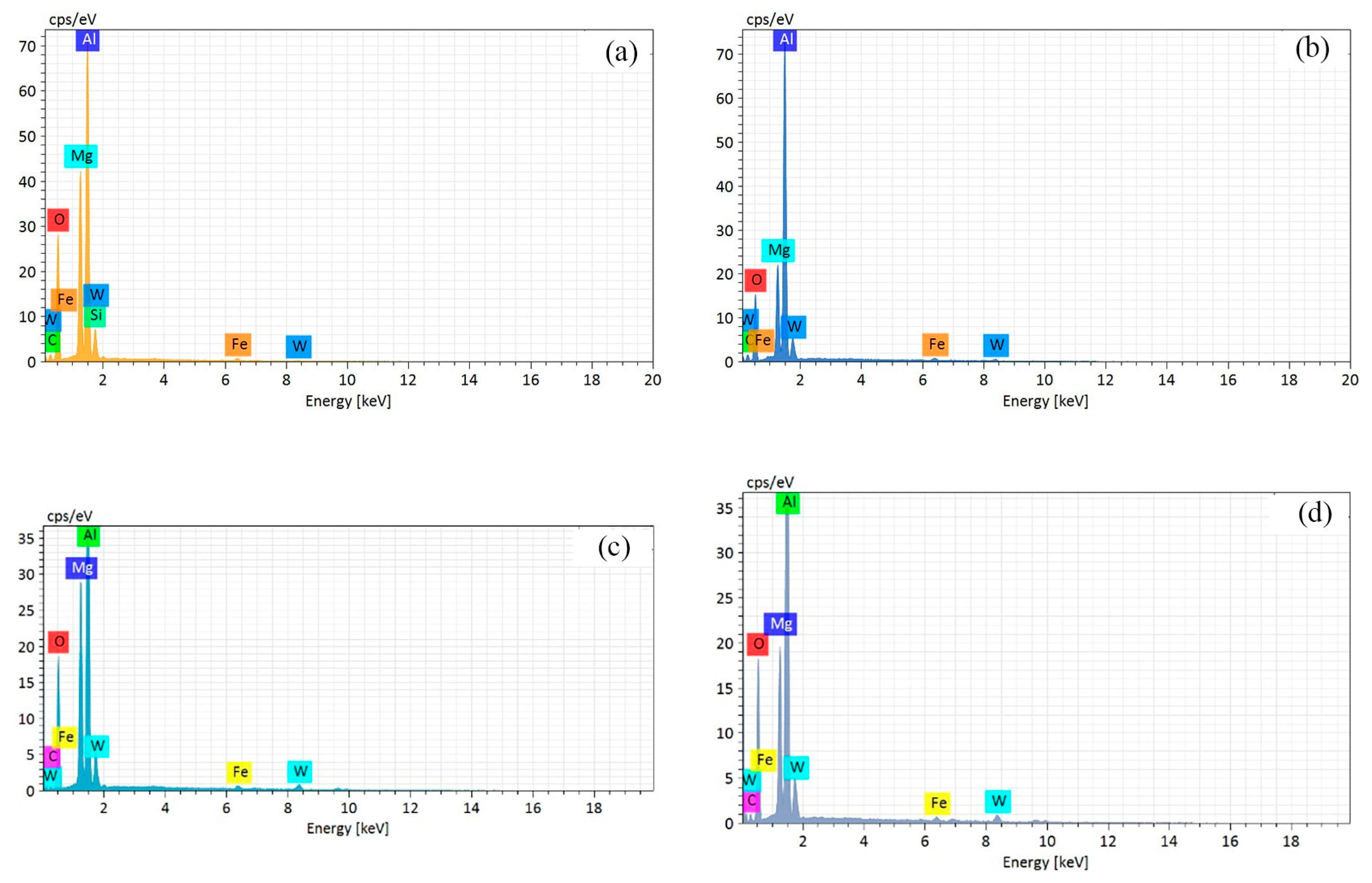
At 0.11 mm/rev, Figure 22a,b shows the wear morphology of the rake face with milling lengths of 20 m and 40 m, respectively. It can be seen that a stable adhesive layer and surface cracks form at the rake face when the milling length reaches 20 m. The thickness of the adhesion layer becomes thicker and the adhesion particles peel off at 40 m. Figure 23a–d explains the EDS spectroscopy results for each point. This shows that aluminum, magnesium, and oxygen are mainly distributed at points A and B, indicating that the rake face wear mechanism is adhesion, oxidation, and abrasive wear at 20 m. There are large amounts of aluminum, magnesium, and oxygen distributed at points C and D, but there are no adhesion particles on the rake face, which indicates that the rake face wear mechanism is adhesion and oxidation wear at 40 m, and no abrasive wear.
In summary, under different feed rates, when the milling length reaches 20 m, the tool–chip interface temperature reaches the maximum value, and the rake face forms a stable adhesion layer and attaches hard particles, resulting in scratches on the rake face, and the wear mechanism of the rake face is adhesion, oxidation, and abrasive wear. When the milling length reaches 40 m, the tool–chip interface temperature decreases, the hard particles of the rake face peel off, and the rake face wear mechanism is adhesion and oxidation wear.
4. Conclusions
Considering the tool–chip interface temperature, the tool wear mechanism of the rake face was analyzed during high-speed milling of ADC12 aluminum alloy in this paper. The cutting temperature was measured under different cutting parameters, and the variation of the tool wear morphology of the rake face and the EDS results were analyzed with increasing milling length. Some conclusions are drawn as follows.
(1) It was found that the tool–chip interface temperature first decreases and then rises with increasing cutting speed, and reaches the lowest at 900 m/min. With increasing feed rate, the tool–chip interface temperature also decreases first and then rises, and reaches the lowest at 0.09 mm/rev. Meanwhile, the tool wear morphology explains that the more serious the adhesion of the tool rake face, the higher the tool–chip interface temperature.
(2) With increasing milling length, the forms of adhesives at the rake face change from hard particles to the coexistence of hard particles and the adhesion layer. The tool–chip interface temperature increases gradually during the formation of the adhesion layer. After that, with increasing milling length, the adhesives gradually stably transform into the adhesion layer. The tool–chip interface temperature decreases gradually with increasing milling length after the adhesion layer forms steadily.
(3) Therefore, the formation mechanism of adhesion wear was discussed. First of all, the hard particles of the chip material adhere to the tool rake face at the beginning of milling. Due to the tool–chip interface frictional effect, the cutting temperature increases gradually. The hard particles melt and transform into the adhesion layer. Owing to the tool–chip interface frictional effect, the delamination appears on the tool rake face, and pits are formed.
Author Contributions
Conceptualization, X.M. and Y.L.; methodology, Y.L.; software, X.M.; validation, X.M.; formal analysis, X.M.; investigation, X.M.; resources, X.M.; data curation, X.M., S.M., and P.Z.; writing—original draft preparation, X.M.; writing—review and editing, X.M.; visualization, X.M.; supervision, Y.L.; project administration, Y.L.; funding acquisition, Y.L. and X.M. All authors have read and agreed to the published version of the manuscript.
Funding
This research was funded by the National Natural Science Foundation of China, grant number 51975123; the funder is Youxi Lin. This research was also funded by the School Research Project of Fujian Jiangxia University, grant number JXZ2022003; the funder is Xinxin Meng.
Data Availability Statement
The data presented in this study are available in the article.
Conflicts of Interest
The authors declare no conflict of interest.
Glossary
| Symbol | Meaning | Unit |
| v | Cutting speed | m/min |
| f | Feed rate | mm/rev |
| L | Milling length | m |
| ap | Cutting depth | mm |
| ae | Cutting width | mm |
| VB | Wear land width | μm |
| Tint | Tool–chip interface temperature | °C |
| F | Cutting force | N |
| φc | Shear angle | ° |
| Lt | Tool–chip contact length | mm |
| vs | Velocity at shear plane | m/min |
| vc | Velocity at rake face | m/min |
| αr | Rake angle | ° |
| h | Instantaneous chip thickness | mm |
| qt | Heat production at shear face | J |
| qf | Heat production at rake face | J |
| θ | Tool rotation angle | ° |
References
- Luo, A.A.; Sachdev, A.K.; Apelian, D. Alloy development and process innovations for light metals casting. J. Mater. Process. Technol. 2022, 306, 117606. [Google Scholar] [CrossRef]
- Xu, J.; Li, L.; Lin, T.; Gupta, M.K.; Chen, M. Machinability analysis in high-speed milling of AlSi7Mg alloys under EMQL conditions: An approach toward sustainable manufacturing. J. Manuf. Process. 2022, 81, 1005–1017. [Google Scholar] [CrossRef]
- Zhang, X.; Gao, Y.; Guo, Z.; Zhang, W.; Yin, J.; Zhao, W. Physical model-based tool wear and breakage monitoring in milling process. Mech. Syst. Signal Process. 2023, 184, 109641. [Google Scholar] [CrossRef]
- Tseng, H.C.; Tsai, M.S.; Yeh, B.C.; Li, K.M. Analysis of Tool Wear by Using a Cutting Bending Moment Model for Milling Processes. Int. J. Precis. Eng. Manuf. 2022, 23, 943–955. [Google Scholar] [CrossRef]
- Meng, X.; Lin, Y.; Mi, S. The Research of Tool Wear Mechanism for High-Speed Milling ADC12 Aluminum Alloy Considering the Cutting Force Effect. Materials 2021, 14, 1054. [Google Scholar] [CrossRef] [PubMed]
- Alshmri, F.; Atkinson, H.V.; Hainsworth, S.V.; Haidon, C.; Lawes, S.D.A. Dry sliding wear of aluminium-high silicon hypereutectic alloys. Wear 2014, 313, 106–116. [Google Scholar] [CrossRef]
- Zhao, G.; Xin, L.; Li, L.; Zhang, Y.; Ning, H.E.; Hansen, H.N. Cutting force model and damage formation mechanism in milling of 70wt% Si/Al composite. Chin. J. Aeronaut. 2023, 36, 114–128. [Google Scholar] [CrossRef]
- Zheng, Z.P.; Lin, N.; Zhao, L.B.; Li, X.; He, Y.H. Fabrication and wear mechanism of Ti(C,N)-based cermets tools with designed microstructures used for machining aluminum alloy. Vacuum 2018, 156, 30–38. [Google Scholar] [CrossRef]
- Oliver, H.; Pete, C.; Martin, J. On the mechanism of tool crater wear during titanium alloy machining. Wear 2017, 374–375, 15–20. [Google Scholar]
- Yoshikawa, H.; Nishiyama, A. CVD diamond coated insert for machining high silicon aluminum alloys. Diam. Relat. Mater. 1999, 8, 1527–1530. [Google Scholar] [CrossRef]
- Rahaman, M.L.; Liangchi, Z. An investigation into the friction and wear mechanisms of aluminium high silicon alloy under contact sliding. Wear 2017, 376–377, 940–946. [Google Scholar] [CrossRef]
- Bhowmick, S.; Banerji, A.; Alpas, A.T. Tribological behavior of Al-6.5%, -12%, -18.5% Si alloys during machining using CVD diamond and DLC coated tools. Surf. Coat. Technol. 2015, 284, 353–364. [Google Scholar] [CrossRef]
- Banerji, A.; Bhowmick, S.; Alpas, A.T. Role of temperature on tribological behaviour of Ti containing MoS2 coating against aluminum alloys. Surf. Coat. Technol. 2017, 314, 2–12. [Google Scholar] [CrossRef]
- Aslantas, K.; Ucun, I.; Çicek, A. Tool life and wear mechanism of coated and uncoated Al2O3/TiCN mixed ceramic tools in turning hardened alloy steel. Wear 2012, 274–275, 442–451. [Google Scholar] [CrossRef]
- Wang, C.Y.; Xie, Y.X.; Qin, Z.; Lin, H.S.; Yuan, Y.H.; Wang, Q.M. Wear and breakage of TiAlN- and TiSiN-coated carbide tools during high-speed milling of hardened steel. Wear 2015, 336–337, 29–42. [Google Scholar] [CrossRef]
- Chen, J.; Yu, W.; Zuo, Z.; Li, Y.; Chen, D.; An, Q.; Chen, M. Tribological properties and tool wear in milling of in-situ TiB2/7075 Al composite under various cryogenic MQL conditions. Tribol. Int. 2021, 160, 107021. [Google Scholar] [CrossRef]
- Venugopal, K.A.; Paul, S.; Chattopadhyay, A.B. Growth of tool wear in turning of Ti-6Al-4V alloy under cryogenic cooling. Wear 2007, 262, 1071–1078. [Google Scholar] [CrossRef]
- Li, X.; Zhou, Y.; Liu, J.; Gao, J. Research on wear mechanism of carbide tool for high-speed cutting aluminum alloy. Powder Metall. Technol. 2018, 36, 256–260. [Google Scholar]
- Rimpault, X.; Il, A.; Chatelain, J.F.; Lalonde, J.F.; Balazinski, M. Workpiece subsurface temperature study during aluminum skin milling in slotting and ramping. Procedia CIRP 2018, 77, 417–420. [Google Scholar] [CrossRef]
- Coz, G.L.; Marinescu, M.; Devillez, A.; Dudzinski, D.; Velnom, L. Measuring temperature of rotating cutting tools: Application to MQL drilling and dry milling of aerospace alloys. Appl. Therm. Eng. 2012, 36, 434–441. [Google Scholar] [CrossRef]
- Karaguzel, U.; Bakkal, M.; Budak, E. Modeling and Measurement of Cutting Temperatures in Milling—ScienceDirect. Procedia CIRP 2016, 46, 173–176. [Google Scholar] [CrossRef]
- Davoodi, B.; Hosseinzadeh, H. A new method for heat measurement during high speed machining. Measurement 2012, 45, 2135–2140. [Google Scholar] [CrossRef]
- Gekonde, H.O.; Subramanian, S.V. Tribology of tool-chip interface and tool wear mechanisms. Surf. Coat. Technol. 2002, 149, 151–160. [Google Scholar] [CrossRef]
- Shaw, M.C.; Cookson, J.O. Metal Cutting Principles. Tribol. Int. 1985, 18, 55. [Google Scholar] [CrossRef]
- Cui, X.; Guo, J.; Zhao, J.; Yan, Y. Chip temperature and its effects on chip morphology, cutting forces, and surface roughness in high-speed face milling of hardened steel. Int. J. Adv. Manuf. Technol. 2015, 77, 2209–2219. [Google Scholar] [CrossRef]
- Cui, D.; Zhang, D.; Wu, B.; Luo, M. An investigation of tool temperature in end milling considering the flank wear effect. Int. J. Mech. Sci. 2017, 131–132, 613–624. [Google Scholar] [CrossRef]
- Altintas, Y. Manufacturing Automation: Metal Cutting Mechanics, Machine Tool Vibrations, and CNC Design, 2nd ed.; Cambridge University Press: Cambridge, MA, USA, 2012. [Google Scholar]
- Tsai, M.Y.; Chang, S.Y.; Hung, J.P.; Wang, C. Investigation of milling cutting forces and cutting coefficient for aluminum 6060-T6. Comput. Electr. Eng. 2016, 51, 320–330. [Google Scholar] [CrossRef]
- Wan, M.; Ye, X.Y.; Yang, Y.; Zhang, W.H. Theoretical prediction of machining-induced residual stresses in three-dimensional oblique milling processes. Int. J. Mech. Sci. 2017, 133, 426–437. [Google Scholar] [CrossRef]
- Zhou, Z. Theory of Metal Cutting; China Machine Press: Beijing, China, 1992. [Google Scholar]
- Bi, J.; Cong, M.; Liu, D.; Xu, X.; Zhao, X. Simulation and experimental analysis of cutting of ADC12 Al-Si alloy. Modul. Mach. Tool Autom. Manuf. Tech. 2017, 1, 127–130. [Google Scholar]
- Schulz, H.; Abele, E.; He, N. The High Speed Machining-Fundamentals and Applications; Science Press: Beijing, China, 2010. [Google Scholar]
- Quan, Y.; Zhao, J.; Li, Y. Surface emissivity calibration for metal cutting tool and workpiece materials with infrared imager. J. Mech. Eng. 2009, 12, 188–192. [Google Scholar] [CrossRef]
Figure 1.
The simplified diagram of the milling process. (a) The milling process; (b) the geometrical relationship of the selected cross-section; (c) the oblique cutting model; (d) the geometrical relationship of oblique cutting.
Figure 1.
The simplified diagram of the milling process. (a) The milling process; (b) the geometrical relationship of the selected cross-section; (c) the oblique cutting model; (d) the geometrical relationship of oblique cutting.
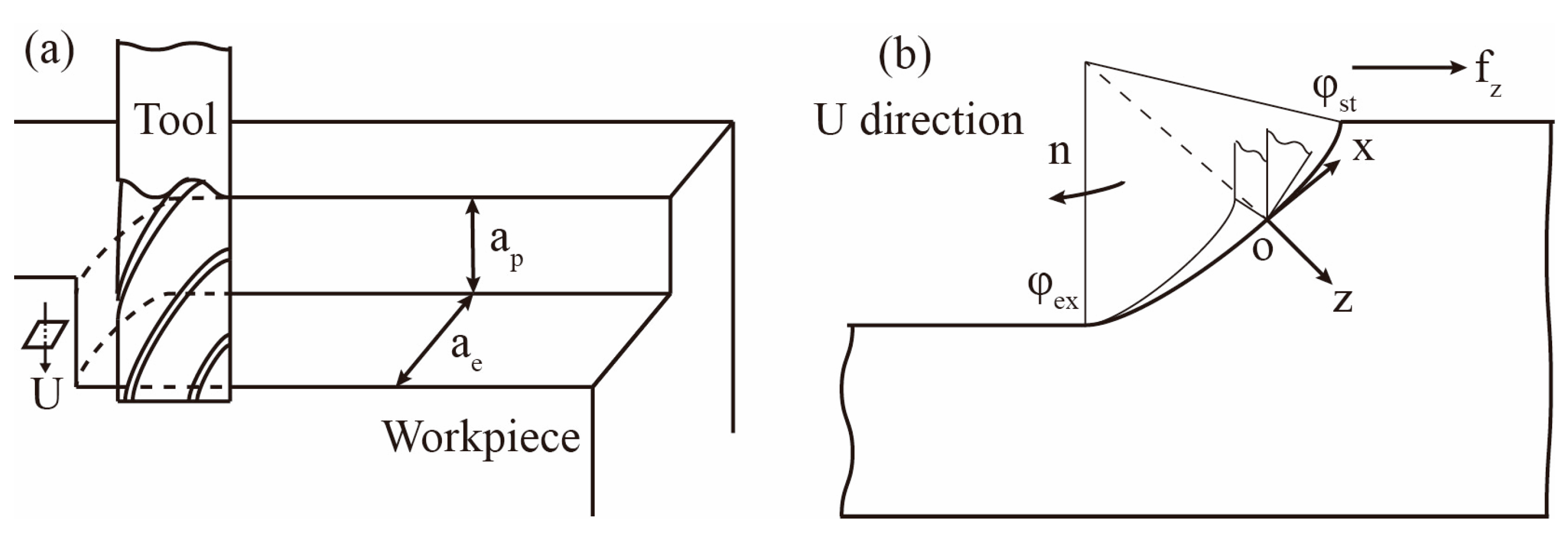

Figure 2.
The heat distribution of two-dimensional orthogonal cutting.
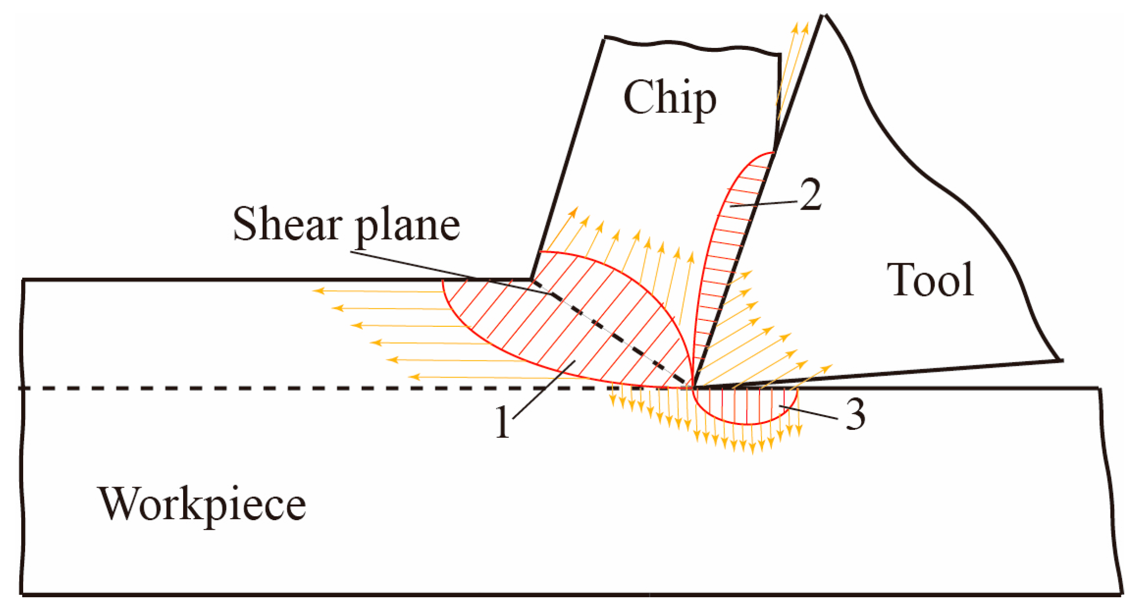
Figure 3.
The milling force of the milling process.
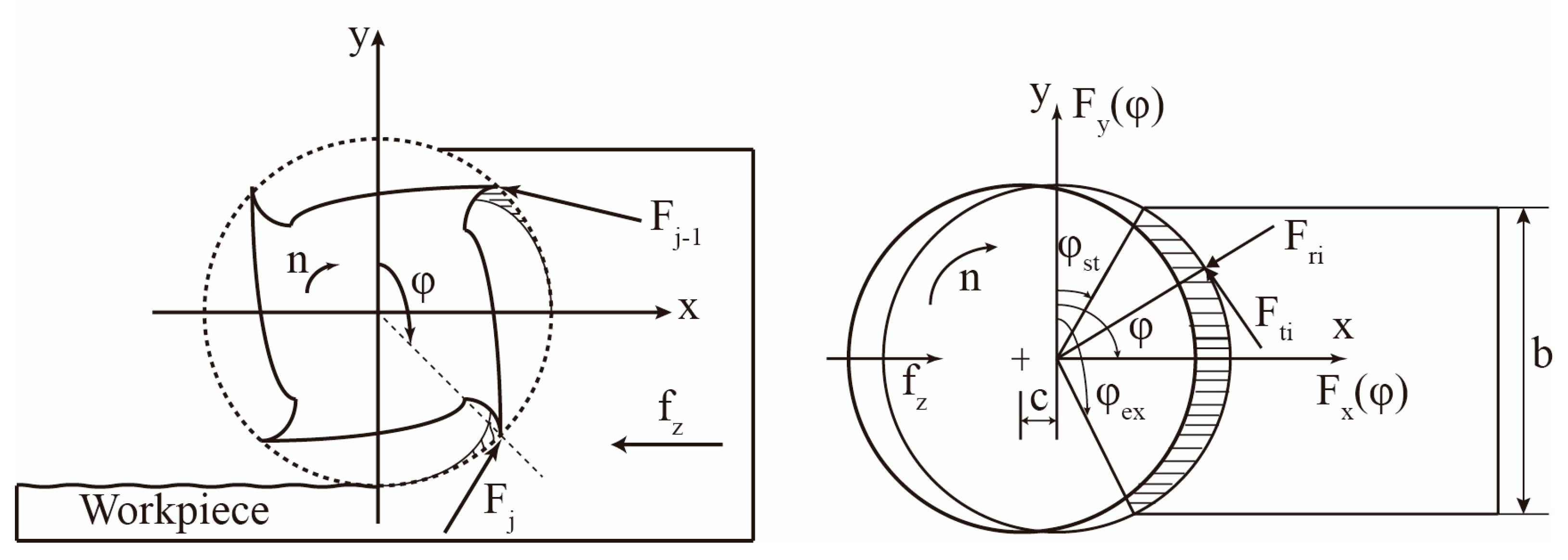
Figure 4.
Milling experimental equipment.
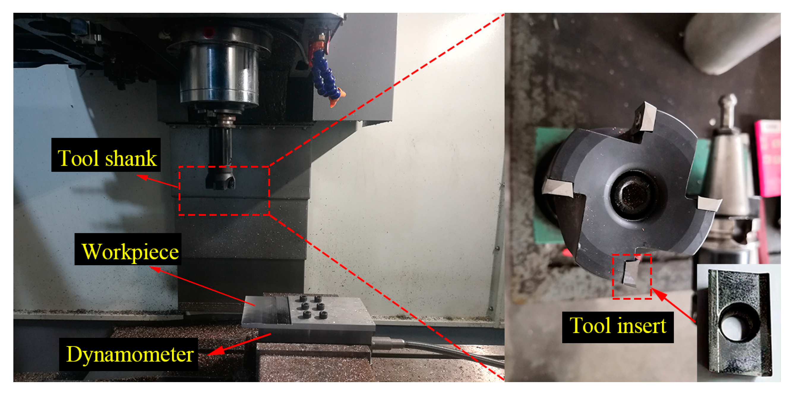
Figure 5.
(a) The cutting force at different cutting speeds; (b) the cutting force at different feed rate.
Figure 5.
(a) The cutting force at different cutting speeds; (b) the cutting force at different feed rate.
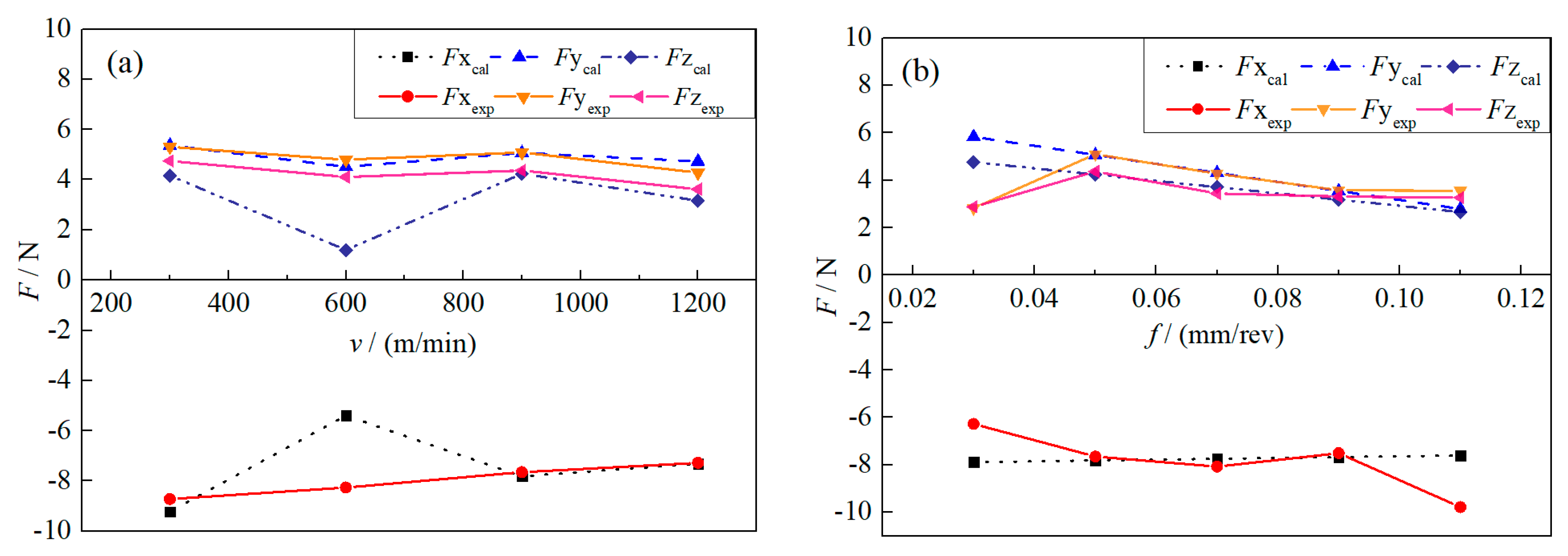
Figure 6.
The variation of heat partition coefficient at different cutting parameters: (a) cutting speed; (b) feed rate.
Figure 6.
The variation of heat partition coefficient at different cutting parameters: (a) cutting speed; (b) feed rate.
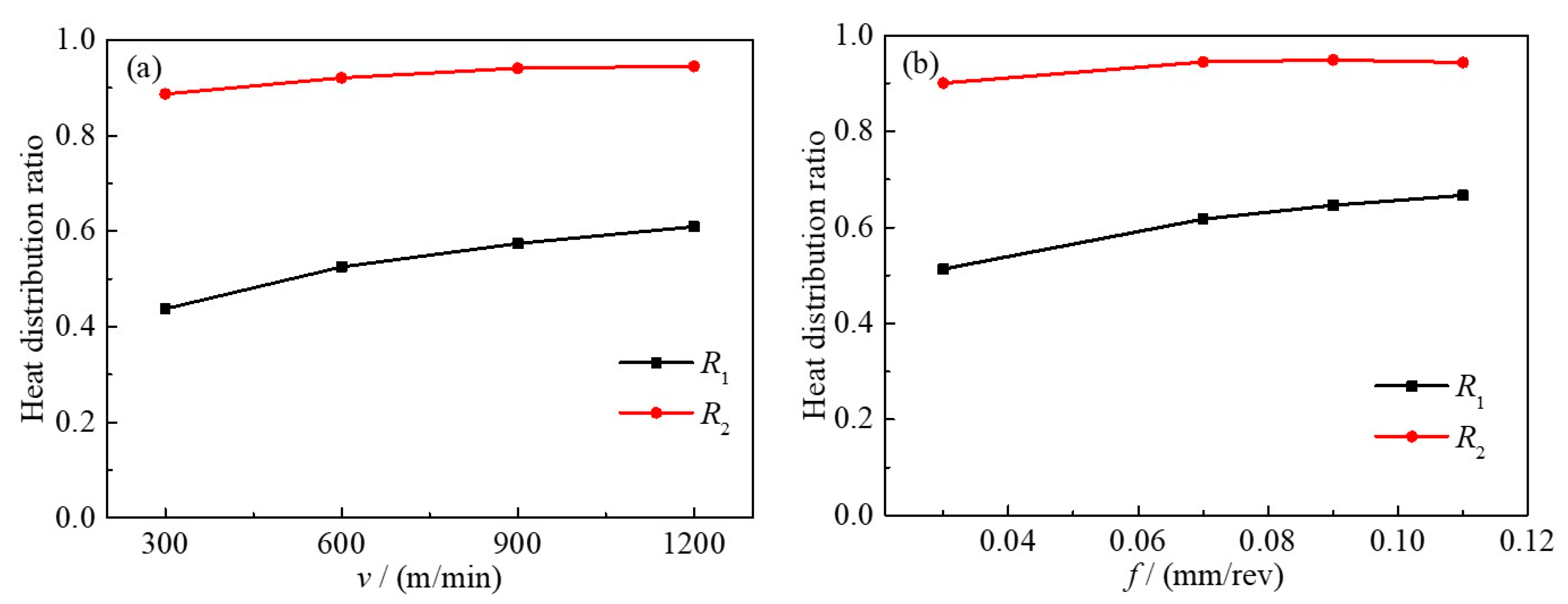
Figure 7.
The variation of tool–chip interface temperature by (a) cutting speed; (b) feed rate.
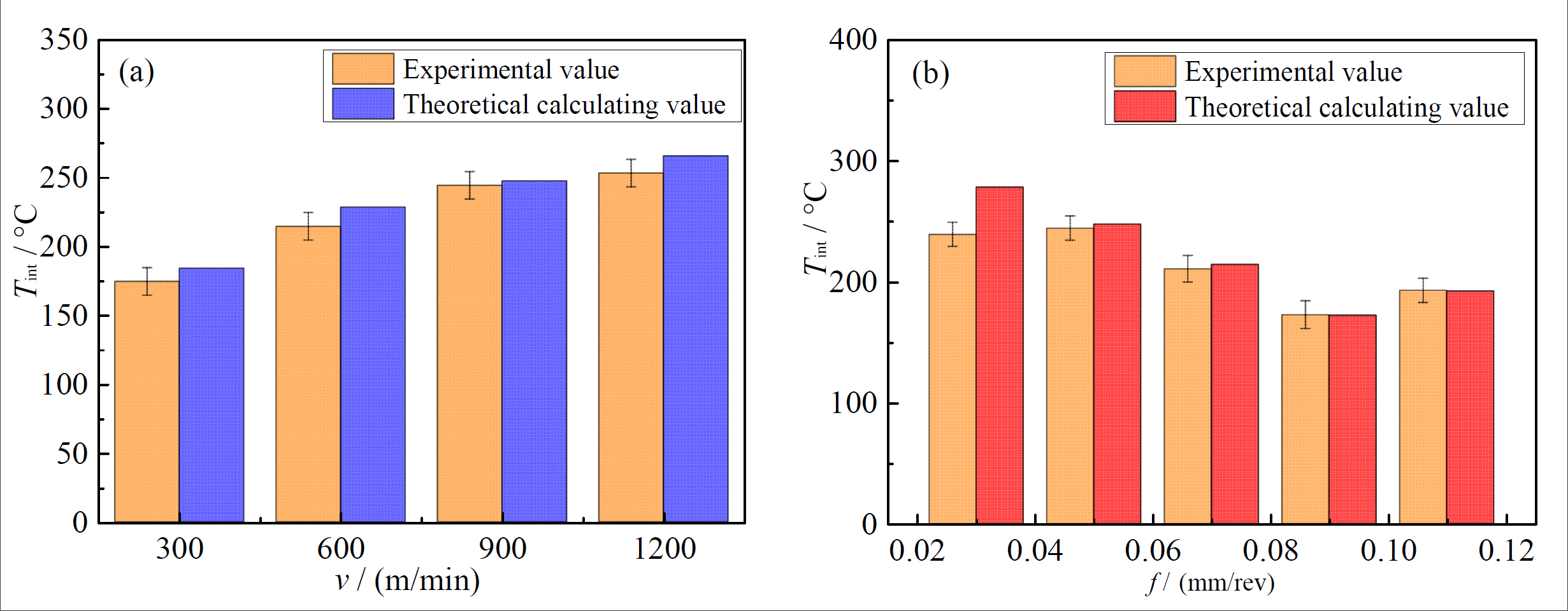
Figure 8.
The variation of tool temperature by (a) cutting speed; (b) feed rate.
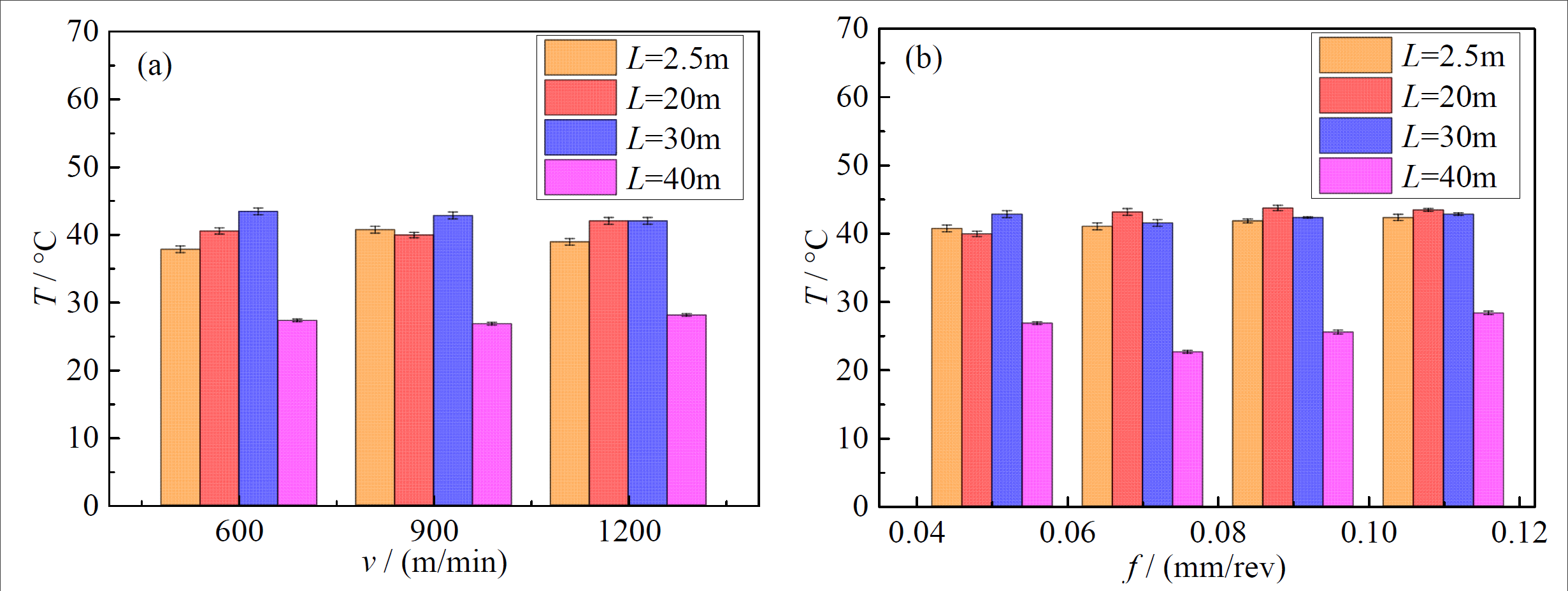
Figure 9.
The variation of tool–chip interface temperature at different cutting length by (a) cutting speed; (b) feed rate.
Figure 9.
The variation of tool–chip interface temperature at different cutting length by (a) cutting speed; (b) feed rate.
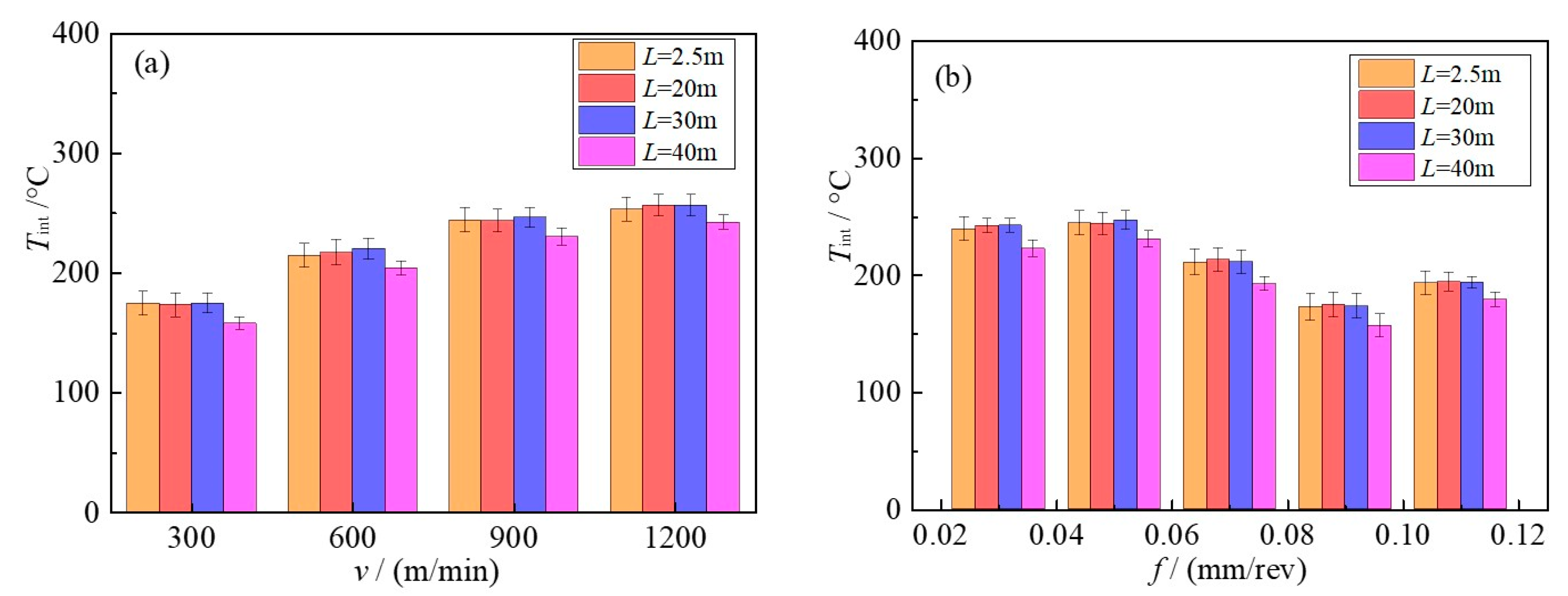
Figure 10.
The cutting force Fx at different milling lengths: (a) 300 m/min; (b) 600 m/min; (c) 900 m/min; (d) 1200 m/min.
Figure 10.
The cutting force Fx at different milling lengths: (a) 300 m/min; (b) 600 m/min; (c) 900 m/min; (d) 1200 m/min.
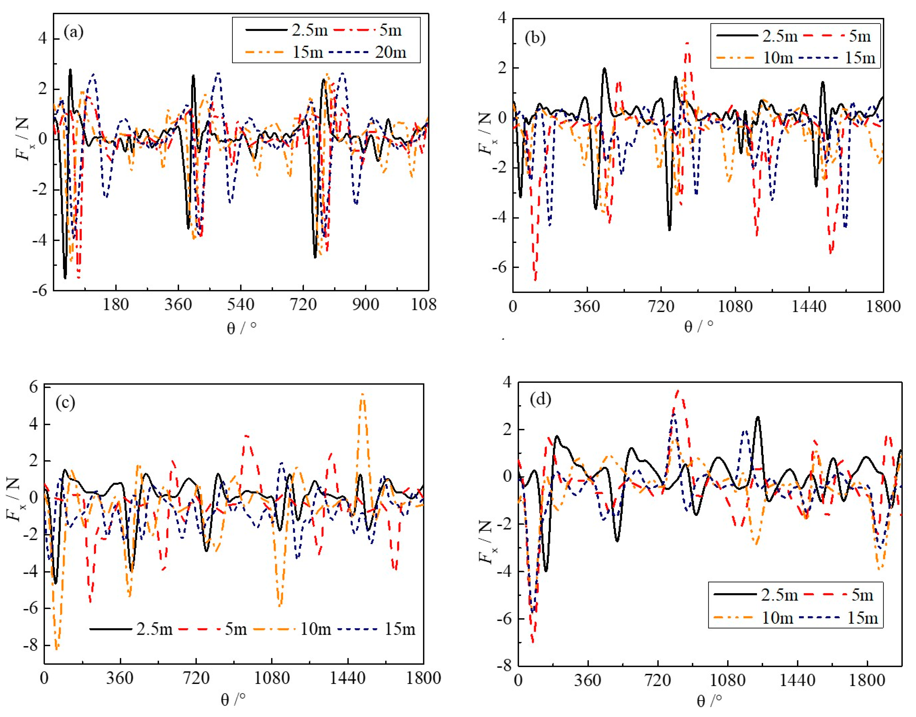
Figure 11.
The tool wear morphology of rake face at 600 m/min at (a) 2.5 m; (b) 20 m; (c) 30 m; (d) 40 m.
Figure 11.
The tool wear morphology of rake face at 600 m/min at (a) 2.5 m; (b) 20 m; (c) 30 m; (d) 40 m.
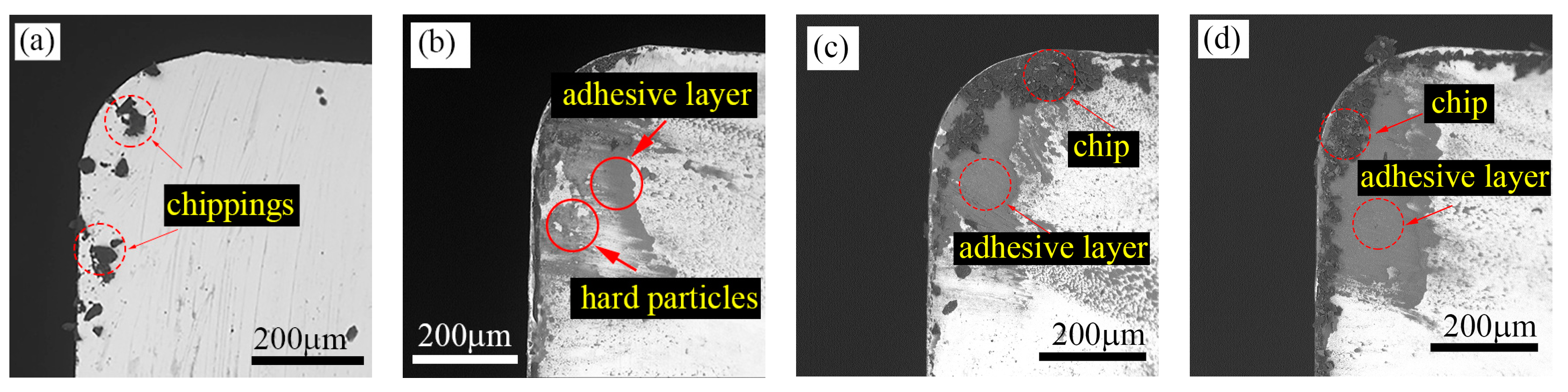
Figure 12.
The tool wear morphology of rake face at 900 m/min at (a) 2.5 m; (b) 20 m; (c) 30 m; (d) 40 m.
Figure 12.
The tool wear morphology of rake face at 900 m/min at (a) 2.5 m; (b) 20 m; (c) 30 m; (d) 40 m.
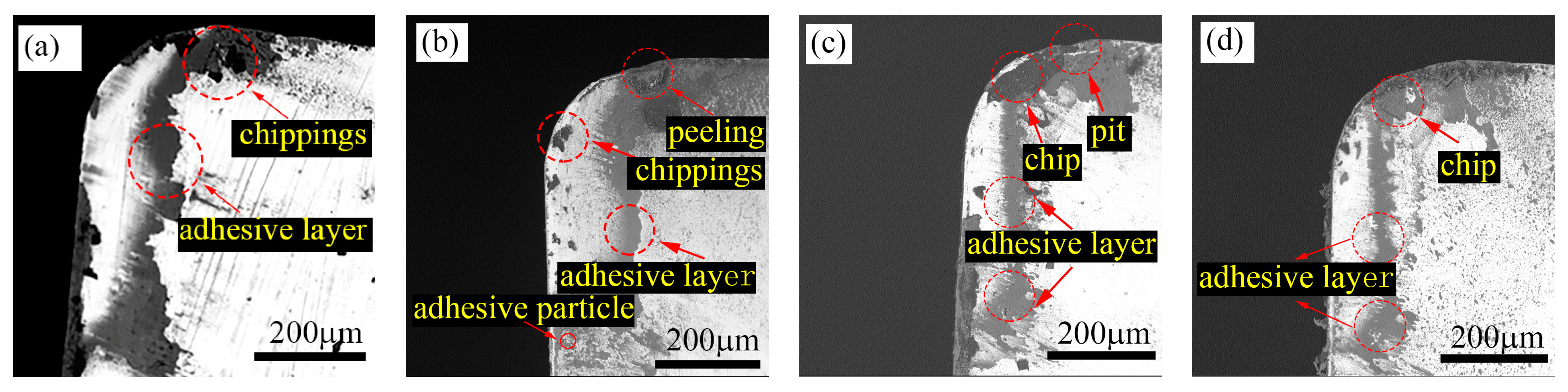
Figure 13.
The tool wear morphology of rake face at 1200 m/min at (a) 2.5 m; (b) 20 m; (c) 30 m; (d) 40 m.
Figure 13.
The tool wear morphology of rake face at 1200 m/min at (a) 2.5 m; (b) 20 m; (c) 30 m; (d) 40 m.

Figure 14.
The wear morphology of rake face at 0.07 mm/rev at (a) 2.5 m; (b) 20 m; (c) 30 m; (d) 40 m.
Figure 14.
The wear morphology of rake face at 0.07 mm/rev at (a) 2.5 m; (b) 20 m; (c) 30 m; (d) 40 m.
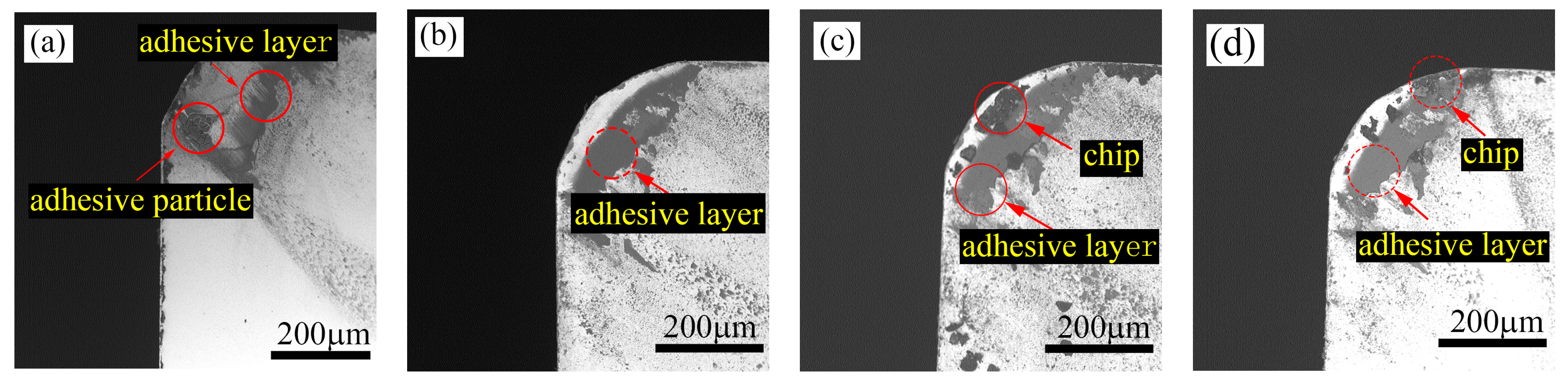
Figure 15.
The wear morphology of rake face at 0.09 mm/rev at (a) 2.5 m; (b) 20 m; (c) 30 m; (d) 40 m.
Figure 15.
The wear morphology of rake face at 0.09 mm/rev at (a) 2.5 m; (b) 20 m; (c) 30 m; (d) 40 m.

Figure 16.
The wear morphology of rake face at 0.11 mm/rev at (a) 2.5 m; (b) 20 m; (c) 30 m; (d) 40 m.
Figure 16.
The wear morphology of rake face at 0.11 mm/rev at (a) 2.5 m; (b) 20 m; (c) 30 m; (d) 40 m.
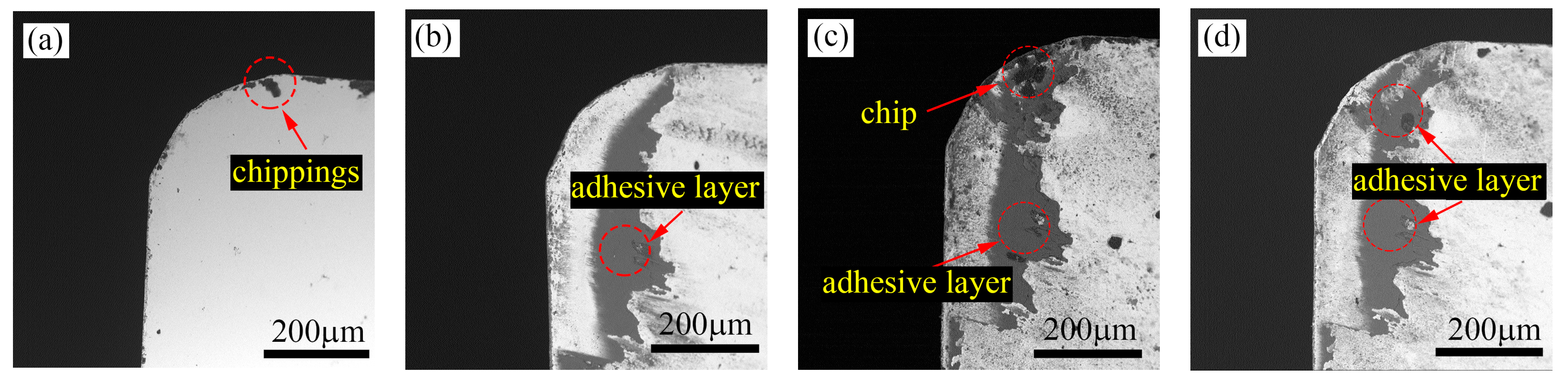
Figure 17.
The tool–chip interface temperature and VB: (a) v = 600 m/min; (b) v = 900 m/min; (c) v = 1200 m/min.
Figure 17.
The tool–chip interface temperature and VB: (a) v = 600 m/min; (b) v = 900 m/min; (c) v = 1200 m/min.
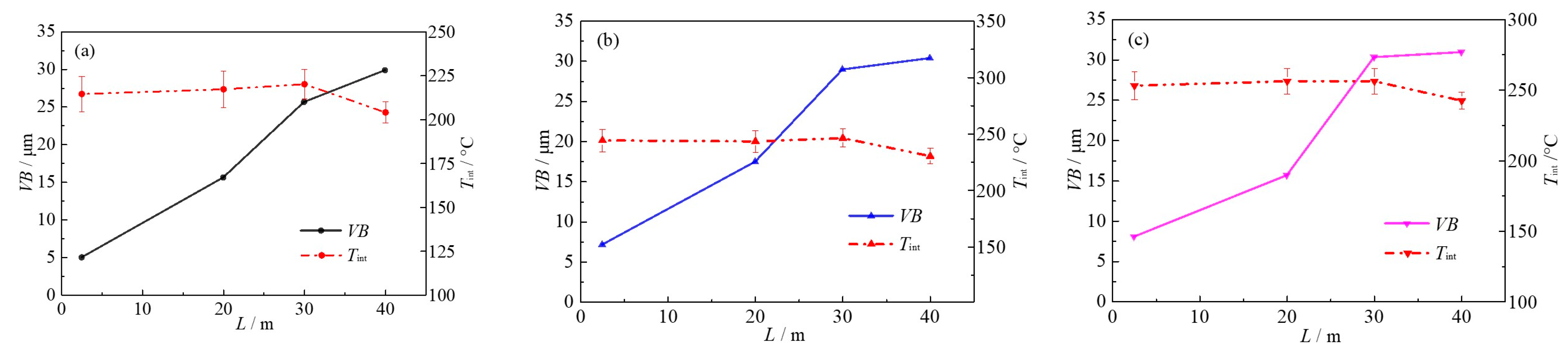
Figure 18.
The tool–chip interface temperature and VB: (a) f = 0.07 mm/rev; (b) f = 0.09 mm/rev; (c) f = 0.11 mm/rev.
Figure 18.
The tool–chip interface temperature and VB: (a) f = 0.07 mm/rev; (b) f = 0.09 mm/rev; (c) f = 0.11 mm/rev.

Figure 19.
The formation of adhesion wear.
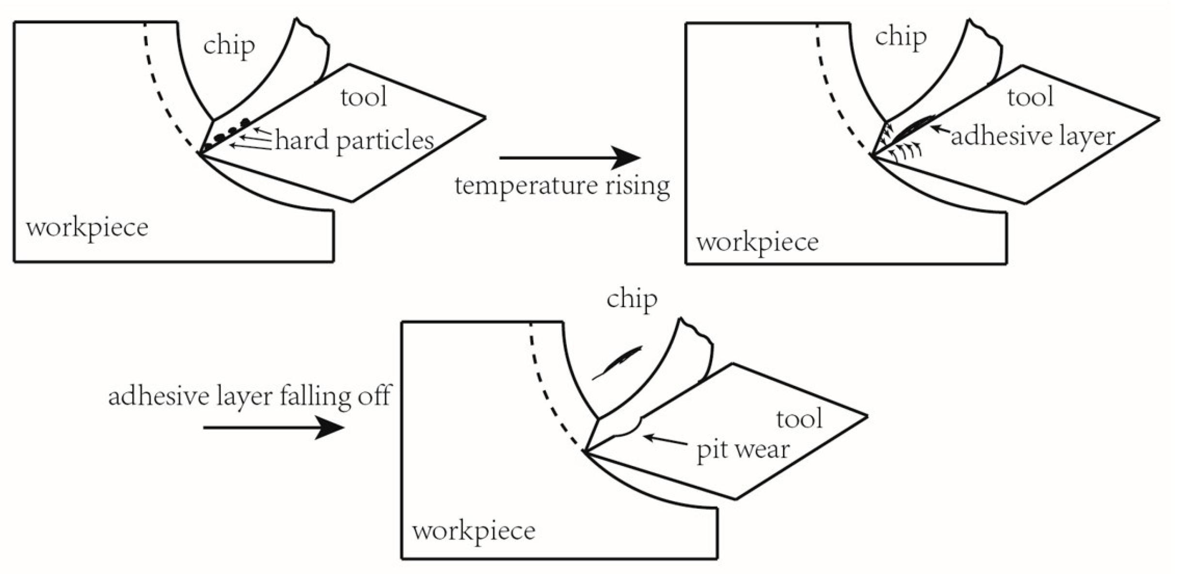
Figure 20.
The tool wear morphology of rake face at 1200 m/min: (a) L = 20 m; (b) L = 40 m.
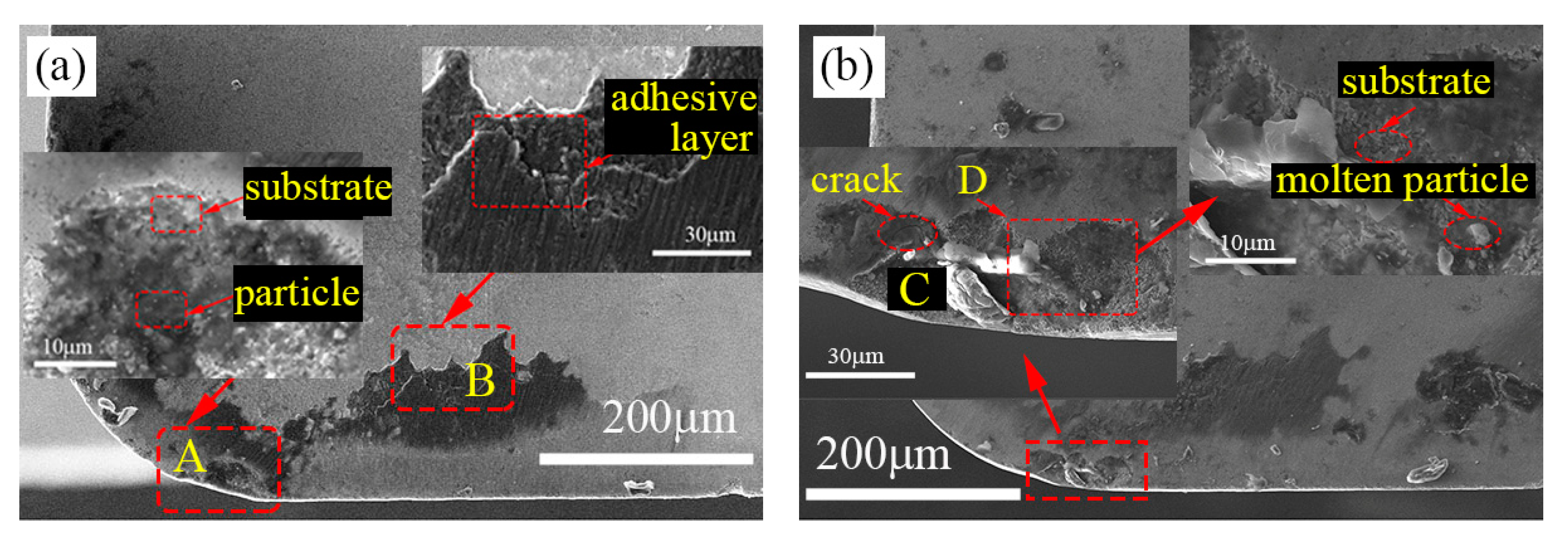
Figure 21.
The EDS results of (a) point A; (b) point B; (c) point C; (d) point D at 1200 m/min
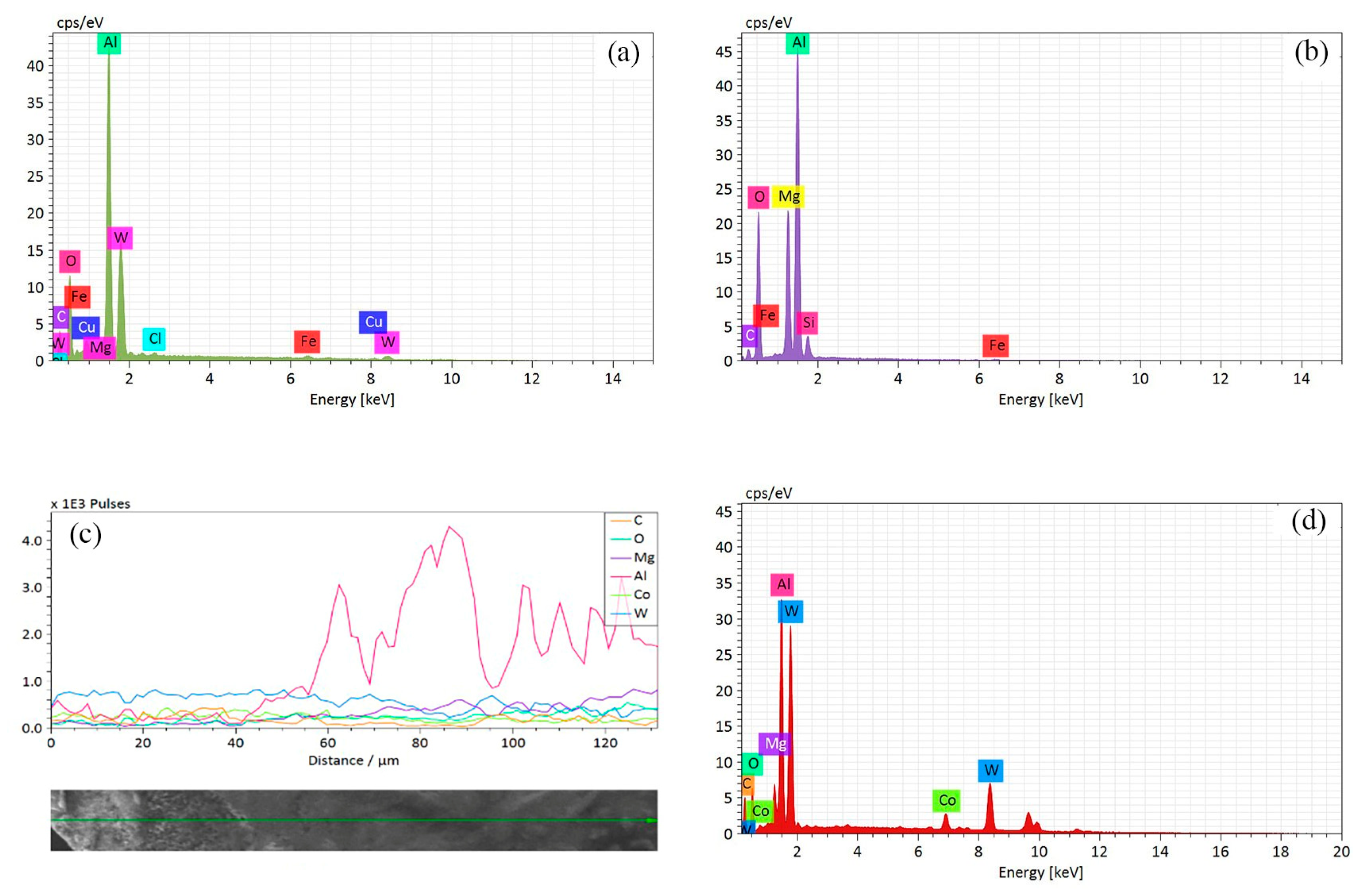
Figure 22.
The wear morphology of rake face at 0.11 mm/rev: (a) L = 20 m; (b) L = 40 m.

Figure 23.
The EDS results of (a) point A; (b) point B; (c) point C; (d) point D at 0.11 mm/rev.

Table 1.
The chemical composition of ADC12 aluminum alloy (wt%).
| Si | Fe | Cu | Mg | Mn | Zn | Ni | Sn | Al |
|---|---|---|---|---|---|---|---|---|
| 9.6–12 | <1.3 | 1.5–3.5 | <0.3 | <0.5 | <1.0 | <0.5 | ≤0.3 | others |
Table 2.
The mechanical properties of the ADC12 aluminum alloy and cutting tool.
| Material Parameter | Workpiece | Tool |
|---|---|---|
| Density/kg·m−3 | 2.67 × 10³ | 15 × 103 |
| Young’s modulus/GPa | 76 | 800 |
| Poisson’s ratio | 0.33 | 0.2 |
| Specific heat/J·kg−1·K−1 | 962 | 200 |
| Thermal conductivity/W·m−1·K−1 | 92.6 | 46 |
| Expansion coefficient/K−1 | 2.06 × 10⁻⁵ | 4.7 × 10⁻⁶ |
Table 3.
Milling experiment parameters of ADC12 aluminum alloy.
| Cutting Parameters | Value |
|---|---|
| Cutting speed/(m/min) | 300~1200 |
| Feed/(mm/rev) | 0.03~0.11 |
| Cutting width/mm | 3 |
| Cutting depth/mm | 0.5 |
| Milling length/m | 0~40 |
Disclaimer/Publisher’s Note: The statements, opinions and data contained in all publications are solely those of the individual author(s) and contributor(s) and not of MDPI and/or the editor(s). MDPI and/or the editor(s) disclaim responsibility for any injury to people or property resulting from any ideas, methods, instructions or products referred to in the content. |
© 2023 by the authors. Licensee MDPI, Basel, Switzerland. This article is an open access article distributed under the terms and conditions of the Creative Commons Attribution (CC BY) license (https://creativecommons.org/licenses/by/4.0/).
Share and Cite
MDPI and ACS Style
Meng, X.; Lin, Y.; Mi, S.; Zhang, P. The Study of Tool Wear Mechanism Considering the Tool–Chip Interface Temperature during Milling of Aluminum Alloy. Lubricants 2023, 11, 471. https://doi.org/10.3390/lubricants11110471
AMA Style
Meng X, Lin Y, Mi S, Zhang P. The Study of Tool Wear Mechanism Considering the Tool–Chip Interface Temperature during Milling of Aluminum Alloy. Lubricants. 2023; 11(11):471. https://doi.org/10.3390/lubricants11110471
Chicago/Turabian StyleMeng, Xinxin, Youxi Lin, Shaowei Mi, and Pengyu Zhang. 2023. "The Study of Tool Wear Mechanism Considering the Tool–Chip Interface Temperature during Milling of Aluminum Alloy" Lubricants 11, no. 11: 471. https://doi.org/10.3390/lubricants11110471
Note that from the first issue of 2016, this journal uses article numbers instead of page numbers. See further details here.