Article

Bionic Design and Optimization of the Wear-Resistant Structure of Piston Rings in Internal Combustion Engines

1
Key Laboratory of Bionic Engineering, Ministry of Education, Jilin University, Changchun 130022, China
2
State Key Laboratory of Automotive Simulation and Control, Jilin University, Changchun 130022, China
3
Machinery Industry Ninth Design Institute Co., Ltd., Changchun 130011, China
*
Author to whom correspondence should be addressed.
Lubricants 2023, 11(11), 484; https://doi.org/10.3390/lubricants11110484
Submission received: 13 June 2023 / Revised: 24 October 2023 / Accepted: 7 November 2023 / Published: 9 November 2023

Abstract

:
Internal combustion engines, during their operation, subject the piston to high-temperature and high-pressure conditions, requiring it to endure intense, continuous reciprocating motion. This strenuous process leads to significant wear and tear. Among the engine’s crucial components, the piston ring plays a pivotal role but is particularly susceptible to wear. Therefore, extensive research has been devoted to investigating the wear of piston rings, a critical sealing component within internal combustion engines. To address the high cost of existing coating methods, which hinders widespread application, we propose a bionic design approach inspired by groove structures observed on earthworm bodies, aimed at enhancing the wear resistance of piston rings. Bionic piston rings featuring optimally designed groove structures inspired by the earthworm’s anatomy were designed. These rings exhibited varying groove depths (1 mm, 2 mm, and 3 mm), groove widths (0.1 mm, 0.3 mm, and 0.5 mm), and groove spacings (0.1 mm, 0.2 mm, and 0.3 mm). We conducted thermal–structural coupling analyses on both standard piston rings and these bionic counterparts. The results revealed that the maximum stress was concentrated at the first piston ring, precisely at the opposing region of the end gap. Thus, the initial piston ring endured the primary frictional losses. Moreover, a comparison of stress levels between bionic rings and the standard ring revealed that the bionic groove structure substantially reduced stress and minimized stress concentration, thus enhancing wear resistance. Groove width had the most notable influence on wear performance, followed by groove depth and groove spacing. Optimal wear resistance was achieved when the groove depth was 3 mm, groove width was 0.1 mm, and groove spacing was 0.1 mm. Subsequently, we constructed a piston ring friction test bench to validate the wear resistance of the most effective piston ring. The results indicated that the wear resistance of the bionic piston ring exceeded that of the standard piston ring by up to 19.627%. Therefore, incorporating a bionic groove structure within the piston ring can effectively reduce surface friction and enhance wear resistance. This, in turn, can enhance the operational lifespan of internal combustion engines under favorable working conditions.

1. Introduction

The internal combustion engine, a hallmark of the second industrial revolution, continues to play a pivotal role in various sectors, notably in transportation. The demand for automobiles powered by internal combustion engines remains substantial. Serving as the central component of vehicles, these engines significantly impact household expenses by maximizing the service life and minimizing the failure rate of automobiles. One critical aspect of the internal combustion engine system is the sealing of the combustion chamber, which is achieved through the piston. This sealing is facilitated by the piston ring situated within the piston groove. The piston ring, a vital component of an internal combustion engine, seals the space between the piston and the cylinder wall to ensure efficient combustion and optimal engine performance. However, piston rings generate friction as they reciprocate along the cylinder liner to maintain the seal. Given their compact structure and demanding working conditions, the piston ring–cylinder (PRCL) friction pair is a key determinant of the internal combustion engine’s service life. Worn piston rings may result in incomplete combustion, leading to increased fuel consumption and emissions. Therefore, the design of piston rings holds significant importance [1]. The issue of wear in mechanical components during motion significantly impacts the durability of machines across various applications [2]. Consequently, the study of wear resistance in piston rings has long been a focal point in enhancing the durability of internal combustion engines [3].
The internal combustion engine operates as a heat engine, where heat is released during the combustion of the internal fuel–air mixture, ultimately transformed into power. Within this system, the piston ring–cylinder liner (PRCL) system assumes a pivotal role, and wear within this system is of paramount significance because energy consumption is a primary cause of engine malfunctions [4]. Friction losses in the engine account for 4–15% of fuel consumption [5], with the PRCL system responsible for roughly 75% of these losses, where the piston rings contribute to more than half of these losses. Consequently, enhancing the friction performance between the piston ring and the cylinder liner holds great potential for increasing the efficiency and service life of internal combustion engines [6].
Effective strategies for reducing friction and wear include increasing the lubricating oil film thickness in the PRCL system [7]. Selecting appropriate materials for piston rings can also mitigate wear in the PRCL system [8]. Improvement measures applied to base materials, such as nitrogen ion implantation for steel piston rings and optimizing the chemical composition for ductile iron piston rings, significantly enhance their strength, toughness, and wear resistance [9].
The mechanical properties of piston ring materials can be augmented through surface modification technology, which significantly reduces friction at the PRCL interface [10]. Techniques such as coating piston rings with zirconia ceramics using plasma spray can reduce wear [11]. Laser treatment, when combined with the appropriate ceramic grains for surface treatment, effectively enhances the friction and wear resistance of piston rings [12]. Furthermore, applying a diamond-like carbon coating through physical vapor deposition results in a lower coefficient of friction [13,14,15,16,17]. Piston rings with CrTiN composite films demonstrate superior hardness and wear resistance at high temperatures [18]. Additionally, coatings with high molybdenum content additives [19] or CrMoN/MoS2 [20] contribute to enhancing the wear resistance and hardness of piston rings. Surface spraying with molybdenum strengthens high-temperature resistance, wear resistance, and oil storage capacity in piston rings. Surface textures or veins are widely adopted to enhance friction performance and improve the friction resistance and wear resistance of piston rings [21,22,23,24,25,26]. While electroplating coatings introduce pollution during the preparation process, thermal spray coatings tend to deform the piston ring during processing. Environmentally friendly physical vapor deposition (PVD) coatings exhibit superior performance, albeit with higher preparation costs [27]. Redesigning the end face structure to some extent also helps reduce piston ring temperatures, extending their lifespan and enhancing overall performance. This provides a cost-effective solution to piston ring problems [28]. However, it is essential to acknowledge that there are limitations to human innovation and improvement within the bounds of our cognitive abilities. Observing nature for design inspiration can serve as an effective approach to address complex real-world challenges and generate innovative designs in various fields [29]. The bionic design approach offers novel solutions for human inventions. Products like radar, airplanes, and robots have drawn inspiration from the observation of nature, providing practical solutions for societal progress and development. The non-smooth surface morphology of organisms has evolved over time, conferring high adaptability to their environment. This adaptation effectively reduces resistance and enhances energy efficiency during movement in specific surroundings [30,31,32]. These advantageous characteristics of non-smooth structures have potential applications in improving the surface properties of mechanical parts. This can lead to reduced drag and enhanced wear resistance [33,34,35,36,37]. Given the successful application of bionic non-smooth structures in engineering, it prompts the question of whether non-smooth structures can be harnessed to enhance the wear resistance of piston rings.
In this study, we examined piston rings subjected to wear and found that a bionic prototype designed to reduce wear exhibited superior wear resistance and drag-reduction characteristics. This prototype was inspired by the earthworm, which can move through soil while experiencing friction with its surroundings [38,39,40].
Volkswagen consistently leads global sales, with the EA211 engine frequently used in Volkswagen models due to its outstanding performance in terms of both technical power and fuel economy. Thus, in our study of the EA211 1.4 L 66 kW MPI small power engine, we designed and optimized a biomimetic groove-shaped non-smooth structure on the piston ring. This design transforms the piston ring’s cross-section into a groove structure similar to that on the earthworm’s surface [41,42].

2. Materials and Methods

2.1. Design of Bionic Piston Ring

The wavy, non-smooth structures that are characteristic features of earthworms endow them with remarkable resistance reduction and wear resistance capabilities (Figure 1) [38]. The way earthworms move in their natural habitat bears a striking resemblance to the working mechanism of an internal combustion engine piston. Hence, in this study, we designed the piston ring to feature a groove-like, non-smooth structure inspired by the strip-like grooves found on the surface of earthworms. To create the bionic piston ring, we acquired point cloud data from a standard piston ring using a three-dimensional laser scanning system (Uniscan, Creaform Inc., Lévis, QC, Canada). These data were then reverse-engineered and modeled in Solidworks 2022 (Figure 2). The groove-shaped, non-smooth structure was superimposed onto the standard piston ring. Specifically, a symmetrical double-groove structure was designed on the contact surface between the piston ring and the cylinder liner (Figure 3). The dimensions of the grooves, including groove depth (D), groove width (W), and groove spacing (L), were varied across three levels. These parameter levels are detailed in Table 1. A comprehensive testing method was employed to configure the bionic surface, resulting in the design of 27 groove-shaped piston rings using different combinations of groove depth, width, and spacing (as presented in Table 5).
To explore the relationship between different groove parameters (D, W, and L) and the wear resistance of the piston ring, we conducted orthogonal analyses based on the values listed in Table 1. When selecting the three parameters’ numerical values, the fundamental strength and stability of the piston ring were ensured. Therefore, we set D at 1, 2, and 3 mm. Given that the radial width of the gas ring within the piston was 4.1 mm, selecting a maximum D of 3 mm still left a margin of 1.1 mm to provide sufficient piston ring strength. As shown in Figure 3, the gas ring’s height was 1.5 mm, and L was symmetrically placed along both sides of the ring’s axis, while W was symmetrically distributed around the axis. Equal values for W and L enhanced the structure’s symmetry and stability. By setting W to a maximum of 0.5 and L to 0.3, we ensured that the air ring retained a 0.1 mm thickness both above and below, preserving the sealing structure.

2.2. Finite Element Method (FEM) Analysis of Piston Rings

We comprehensively analyzed the multifaceted factors influencing the wear resistance of internal combustion engine piston rings, including the mechanical motion and thermal stress under real-world operating conditions. We selected the piston ring–cylinder liner system of the Volkswagen EA211 1.4 L 66 kW MPI low-power version of the internal combustion engine as the primary focus. Using Solidworks 2022 software, we developed models for the engine components and the mechanical transmission system. We then performed thermal–structural coupling pre-processing on both the standard piston ring and the designed bionic piston ring, employing the finite element analysis software ANSYS 2022 Workbench and theoretical computational boundary conditions. Through the simulations, experimental factors such as the surface stress and deformation of the piston ring were determined.

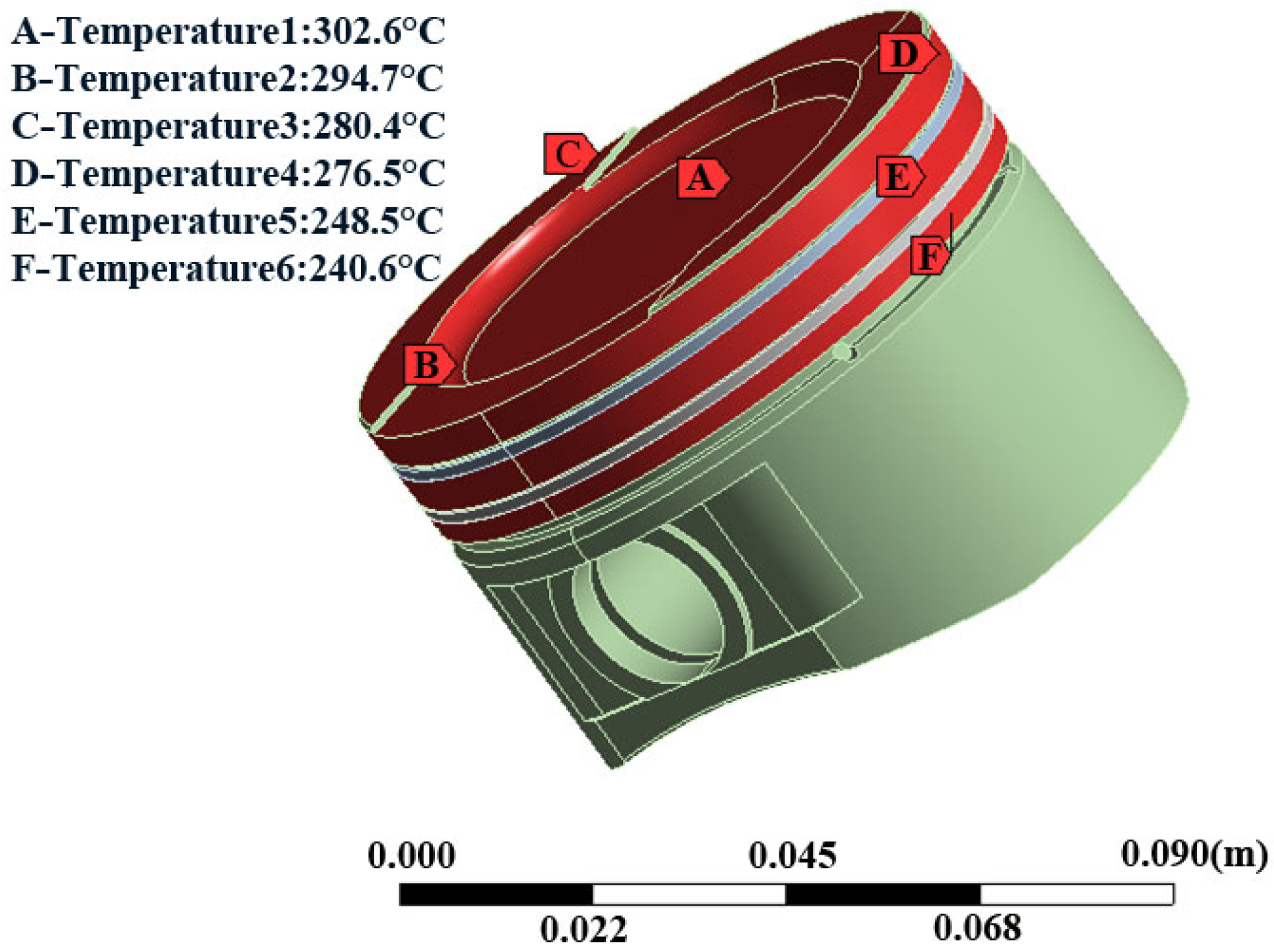
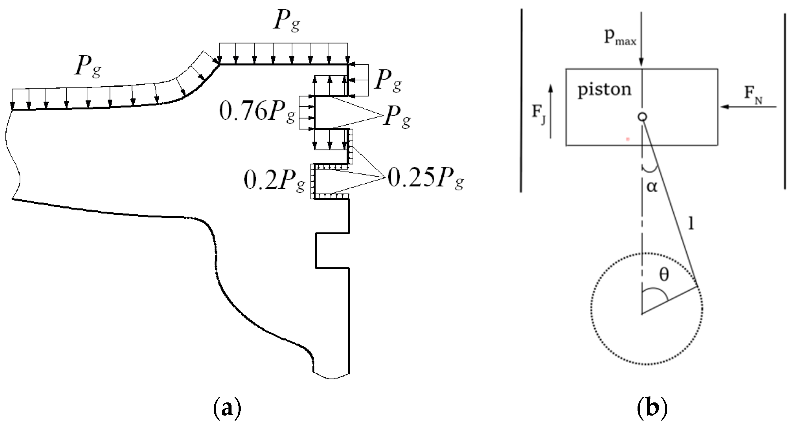
2.2.1. Analysis Model and Boundary Conditions

Point cloud data of the piston were also obtained using a three-dimensional laser scanning system (Uniscan, Creaform Inc., Lévis, QC, Canada) and were modeled using a three-dimensional laser scanning system. In Solidworks 2022, we assembled the piston and piston ring, creating a piston assembly model. Figure 4 illustrates this model, featuring both standard and bionic piston rings. Subsequently, we developed models for the piston assembly and the mechanical transmission system in Solidworks 2022.
Within the ANSYS 2022 software, we first established the steady-state thermal and static structural modules as the foundation for our analysis. We synchronized the material parameters of the piston ring model and set up the model’s import and meshing. The results from the steady-state thermal and static structural finite element analyses were then incorporated into the static structural module. Specifically, steady-state temperature field finite element analysis results were introduced into the structural static module. Adhering to the actual piston ring and piston materials of the Volkswagen EA211 1.4 L 66 kW MPI low-power version gasoline engine, we configured the piston ring and piston material parameters in the Engineering Data of the steady-state temperature field module, referring to the material properties table for commonly used metal materials (as detailed in Table 2 and Table 3).
In the following steps, the piston rings and piston assembly models were imported and meshed as a unified whole within the finite element analysis software ANSYS Workbench V17.0. To prevent the occurrence of separation between the piston ring and the piston, the contact mode between the piston ring’s back and the lateral surface of the piston ring was set as “Bonded”. This ensured the stability of the piston assembly model during the meshing process. Given the relatively smaller size of the piston ring compared to the piston, subgridding techniques were employed to manage the piston ring surfaces and the bionic groove-shaped non-smooth surfaces. Hex-dominant meshes were generated in these areas, and local refinement settings were applied, with a local refinement level set to 1. Figure 5 depicts the mesh division of the piston rings and piston assembly models.
Subsequently, the piston rings were assigned temperature fields, loads, and other boundary conditions. Following this setup, thermal–structural coupling analysis was conducted for both the standard piston rings and the bionic piston rings.
To obtain definite solutions for each node in the differential equation of the steady temperature field, we established initial and boundary conditions. We adopted the third thermal boundary condition for calculating the steady temperature field of the piston rings. During the power stroke of the PRCL system, high-temperature and high-pressure gas within the cylinder initially impacts the piston’s top surface. Then, it undergoes a series of energy transfer and dissipation steps.
In selecting the third thermal boundary condition, we must have access to the heat transfer coefficients.
The heat transfer coefficient α g on the piston top was determined using Eichelberg’s equation:
α g = K 0 C m 3 P g T g
where K 0 is the correction factor, C m is the mean speed of the piston (m/s) and is calculated based on the Equation (2), P g is the instantaneous pressure of the gas at the piston top (MPa), and T g is the instantaneous temperature of the gas at the piston top (K).
C m = 2 S t = S n 30
where S is the piston stroke (m), t is the cycle time of the piston (s), and n is the crankshaft speed (r/min).
In the context of a working cycle in an internal combustion engine, the average heat transfer coefficient α m and average temperature T m of the fuel gas at the piston top’s surface are:
α m = 1 4 π 0 4 π α g d φ
T m = 0 4 π α g T g d φ 0 4 π α g d φ
where φ is the crank angle (rad).
The heat transfer coefficients for the piston top land, piston ring, and piston skirt are computed as follows:
1 α n = δ i λ i + 1 α w
where δ i denotes the thickness of oil film, piston ring, or cylinder liner (m); λ i denotes the corresponding heat transfer coefficient; and α w is the heat transfer coefficient between the cylinder liner and cooling water calculated as follows:
α w = 300 + 1800 G v A
where G v denotes the flux of cooling water (m3/s), and A denotes the average section area of the water-cooling channel in the cylinder liner (m2).
The heat transfer coefficients were calculated, and subsequently, the steady temperature field was determined using the third thermal boundary condition. Specific values for each variable are detailed in Table 4.
In this phase, the temperature distribution and heat transfer coefficients, as detailed in Table 4, were employed to apply a temperature load to the model. Figure 6 presents the steady-state temperature distribution of the piston ring group, which was calculated.
When the compressed gas ignites, the piston rings experience primary forces, primarily the axial gas pressure, reciprocating inertia force, and radial pressure. During the working stroke of the internal combustion engine, the high-temperature, high-pressure gas produced from the combustion of fuel gas exerts its influence on the piston top before reaching the piston ring surfaces. Figure 7 illustrates the pressures at various piston locations [43,44,45], with Pg representing the instantaneous gas pressure at the piston’s top during any given crankshaft rotation position. As per actual working conditions, the maximum pressure was set at Pmax = 10 Mpa.
While the piston set and connecting rod undergo reciprocating linear motion with variable velocity along the cylinder axis, they are subject to an inertia force Fj:
F j = m j a j = m j r ω 2 cos θ + l cos 2 θ
where m j denotes the weight of the piston rings (kg); a j denotes the reciprocated acceleration of the piston rings (m/s2); ω denotes the rotation angular velocity of the crankshaft, ω = 2 π n 60 (rad/s); n denotes the rotating speed of the crankshaft; θ denotes the rolling angle of the crankshaft (rad); and l denotes the length of the connecting rod (m).
During the piston rings’ reciprocating motion, the lateral pressures generated by the crank’s connecting rod mechanism induce secondary movement in the piston rings. The lateral pressure F N can be determined as follows:
F N = F tan α
where F denotes the resultant force of the gas pressure and inertia force imposed on the piston rings (N); α denotes the swing angle of the connecting rod (rad).
The results from the temperature distribution phase were imported into the piston ring’s static structural analysis module. Based on the outcomes of the steady-state temperature distribution analysis and the forces affecting the piston rings and cylinder liner system during the working process, we conducted FEM analysis on the piston rings through the thermal–structural coupling method.

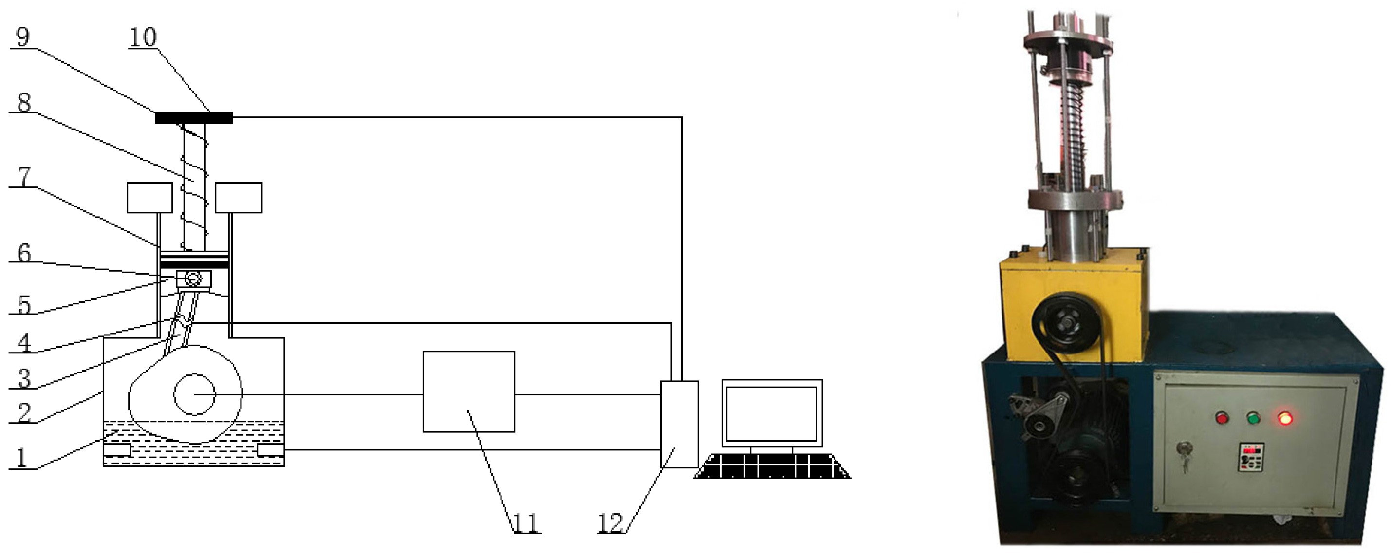
2.2.2. Wear Resistance Validation Test

To confirm the wear resistance of piston rings under real-world operational conditions, we designed a reciprocating friction test bench for internal combustion engines with a single-cylinder piston (Figure 8). The test adhered to the Road Vehicles Engine Test Code (GB/T 18297-2001) and Road Vehicles Engine Cylinder Liner Technique Conditions (QC/T 570-1999 (2009)). This test bench allowed dynamic measurement of friction between piston rings and the cylinder liner. The generator (11) rotated the crankshaft, which, in turn, drove the piston ring and cylinder liner system through the cam connecting rod (3) in reciprocating motion. The spring (9) applied pressure to the piston, simulating the gas pressure on the piston’s top surface under actual working conditions. The pull pressure sensor (4) measured the pull/press force of the cam connecting rod (3), while the pull pressure sensor (10) gauged the pull/press force of the compression spring (9). Data were collected using the data acquisition system (Arizon Technology, Yangzhou, China, FD 0843) and saved in Excel format, with a sampling rate of 400 Hz. The difference between these two forces represented the friction force between the piston ring (5) and the cylinder liner (6). The measured friction data were used to assess whether the bionic design could reduce friction resistance, impacting wear and visually reflecting the wear resistance of the piston rings. A smaller friction force indicated higher wear resistance.
The bionic piston ring structure was processed using wire cutting, and the piston ring’s surface was thoroughly cleaned with alcohol before experimentation. The grooves’ interior, especially, received meticulous cleaning with an ultrasonic cleaner. A small amount of lubricating oil (SAE 5W40) was applied to both the standard piston ring and the processed bionic grooved piston ring. This step was repeated before each experiment to ensure proper lubrication. The test stand was installed within the cylinder liner according to the test’s design. Before each test, the piston ring underwent a 30 min, 800 r/min idle speed break-in test. During this time, the test stand’s operation and the friction numerical curve in the computerized acquisition system were continuously monitored to guarantee stable operation. If any anomalies occurred, power was immediately cut to stop the machine, and the test bench was inspected. The test bench operation was thoroughly debugged to ensure it reached an optimal state, and the friction acquisition system consistently collected a stable friction force change curve. The motor speed was set to 1500 r/min for the wear resistance test, which lasted 30 min. During the experimental tests, the piston and cylinder liner temperatures were maintained around 250–350°. The computerized friction acquisition system was used to obtain the friction value on the piston ring’s friction surface. For force measurement, we employed the S-type tensile force transducer VS52 (Shenzhen Wisdom, Shenzhen, China), ensuring that the friction force matched that of the ring. Data collected within the system were imported into Excel 2023 software, ready for verification and analysis of the piston ring’s wear-resistant performance. After one round of experiments, the piston ring and the test bench were cleaned, and the installation and testing process was repeated. Three rounds of experiments were carried out for each type of piston ring to collect friction data and verify their statistical significance.

3. Results and Discussion
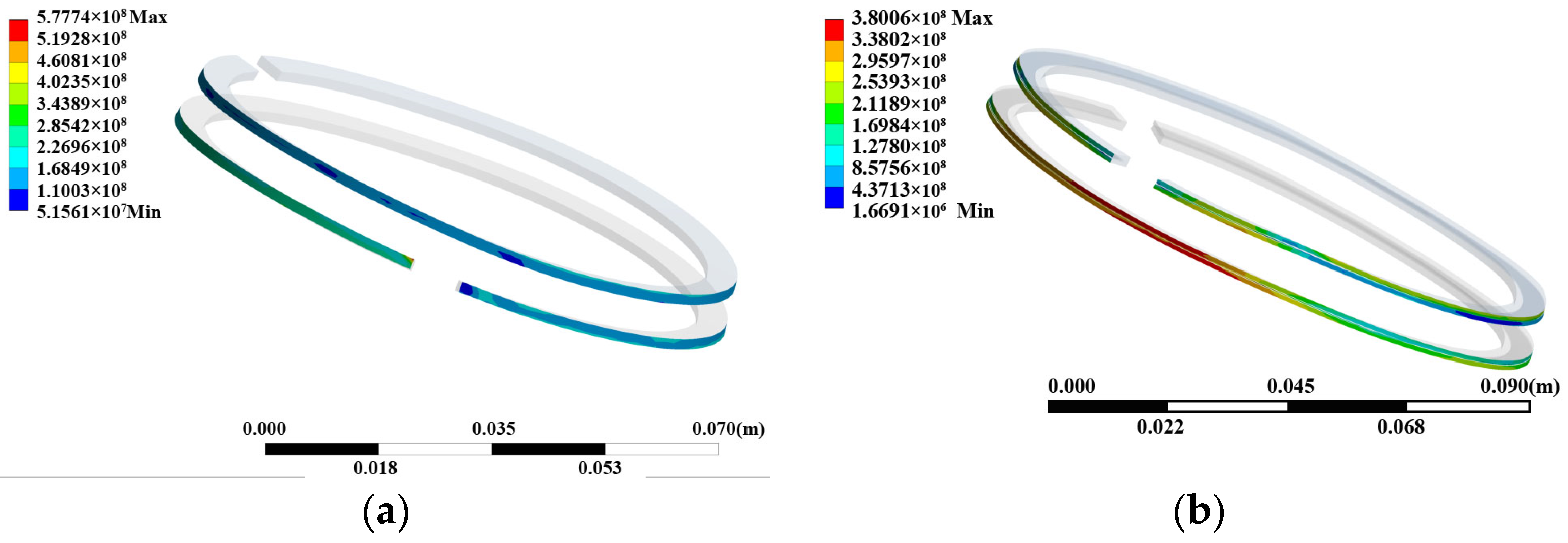
3.1. Results of FEM

Figure 9 displays the stress distribution contour maps of the standard piston rings and the bionic piston rings.
The equivalent stress distribution contour of the standard piston ring set (Figure 9a) reveals that the primary stress on the piston ring set is borne by the first air ring. Its maximum equivalent stress measures 577.7 MPa, a value within the material’s yield strength range. The highest stress occurs on the opposite side of the first air ring’s opening. This is due to the piston ring being compressed by the cylinder liner during assembly, causing the two ends of the piston ring opening to close continuously, resulting in the highest stress at the opposite side of its opening. By examining the stress contour on the outer surface of the bionic piston ring set through thermal–structural coupling finite element analysis (Figure 9b), it becomes evident that the highest stress value on the outer surface of the bionic piston ring set occurs on the surface of the piston ring opposite to the first gas ring’s opening. This suggests that the first gas ring bears the primary frictional power consumption during the piston ring set’s operation. The stress distribution on the outer surface of the piston ring gradually decreases from the position opposite to the opening toward the ring’s opening. A certain amount of stress was also observed within the bionic groove-shaped structure. Table 5 summarizes the maximum stress on the external surfaces of the bionic piston rings, along with range analysis results.
Evidently, the maximum external surface stress for all bionic groove-shaped piston rings, except No. 8, is lower than that of the standard piston ring. In particular, the No. 19 bionic piston ring, featuring a groove depth of 3 mm, groove width of 0.1 mm, and groove spacing of 0.1 mm, exhibits a maximum stress of 339.1 MPa, which is 41.3% lower than the standard piston ring with the most significant drag reduction rate. These results indicate that this bionic groove structure can efficiently enhance the wear resistance of piston rings. To establish significance, a comprehensive comparison is required rather than evaluating each pair. Thus, we adopted a range-based method. The range R j was obtained by calculating the difference between the maximum and minimum average values for each factor. The larger the range R j , the greater the significance of the influence factors. Range analysis results indicate that the width (W) is the most influential bionic parameter for affecting wear resistance, followed by depth (D). Meanwhile, spacing (L) is less influential than depth (D). Therefore, the No. 19 bionic piston ring with a groove depth of 3 mm, groove width of 0.1 mm, and groove spacing of 0.1 mm displays the most impressive wear resistance.
Table 5. Experimental scheme and simulation results.
Serial NumberDepth
D/mm
Width
W/mm
Spacing
L/mm
Max Stress
yi/MPa
110.10.1450.7
210.10.2348.4
310.10.3379.1
410.30.1489
510.30.2380.1
610.30.3449.2
710.50.1416.4
810.50.2595.4
910.50.3455.6
1020.10.1354.6
1120.10.2358.6
1220.10.3349.9
1320.30.1449.5
1420.30.2362.6
1520.30.3361.7
1620.50.1391.1
1720.50.2359.4
1820.50.3443.9
1930.10.1339.1
2030.10.2349.2
2130.10.3340.6
2230.30.1340.8
2330.30.2472.2
2430.30.3354
2530.50.1385.2
2630.50.2498.6
2730.50.3392.6
y j 1 ¯ 440.43363.36401.82
y j 2 ¯ 381.26406.57413.83
y j 3 ¯ 385.81437.58391.84
R j 59.1874.2221.99
Order of importanceW > D > L

3.2. Results of Wear Resistance Validation

Based on our previous analysis, the bionic groove-shaped piston ring in the No. 19 group, with a groove depth of 3 mm, groove width of 0.1 mm, and groove spacing of 0.1 mm, displayed the best wear resistance. However, considering the results of the thermal–structural finite element analysis, the No. 2 and No. 12 bionic piston rings exhibited higher stresses on their outer surfaces, while the No. 20, No. 21, and No. 23 bionic piston rings experienced higher stresses at the openings. Therefore, this study selected six bionic groove-shaped structures from Table 5, No. 2, No. 12, No. 19, No. 20, No. 21, and No. 23, for surface modifications on the original piston ring of the Volkswagen EA211 1.4 L 66 kW MPI low-power internal combustion engine. Subsequently, validation experiments were conducted using the standard piston ring set in the designed piston ring wear-resistant and sealing performance test bench. We utilized Origin to create the friction curves, as shown in Figure 10.
We selected five working periods and identified the maximum friction force during each period. We calculated the average friction, f ¯ = f 1 + f 2 + + f n n , where f was defined as the friction, and determined the percentage of wear resistance improvement, η = f b i o n i c ¯ f s t a n d a r d ¯ f s t a n d a r d ¯ × 100 % . The results are listed in Table 6. A statistical analysis revealed that p < 0.05 for the rate of resistance reduction, indicating statistical significance.
The bionic piston rings exhibited smaller average friction and wear resistance improvements of up to 19.63%, underscoring the effective reduction in surface friction and enhanced wear resistance attributed to the bionic groove-shaped structure of the piston rings.
The comprehensive analysis of the six piston ring surface friction and drag reduction rate datasets, the wear resistance test bench experimental results, and the previous thermal–structural coupling finite element analysis results revealed that the groove depth of 3 mm, groove width of 0.1 mm, and groove spacing of 0.1 mm in the No. 19 bionic groove-shaped piston ring led to the smallest average friction and the most significant drag reduction rate at 19.63%, demonstrating superior wear resistance. Following closely were the No. 20 and No. 21 bionic groove-shaped piston rings, which exhibited drag reduction rates of 17.52% and 15.00%, respectively, along with improved wear resistance. This confirms that the bionic groove structure on the piston ring’s surface effectively minimizes surface friction and enhances the wear resistance of the piston ring set.

4. Discussion

The thermal–structural FEM analysis and wear resistance validation test reveal that the bionic groove-shaped structure significantly enhances the wear resistance of piston rings. Piston rings incorporating bionic grooves feature a reduced end-face area compared to standard rings. This reduction reduces the contact area with the cylinder wall, leading to decreased friction. Additionally, the grooves on the side of the ring enhance gas flow within the ring grooves to some extent, further reducing ring temperature.
In summary, groove width exerts the most significant influence on the wear resistance of the piston ring’s outer surface when groove depth and spacing remain unchanged. The stress on the outer surface of the bionic piston ring with a groove width of 0.1 mm is the lowest, making it superior in enhancing surface wear resistance. The relationship between groove depth and the maximum stress on the piston ring’s outer surface is linear, with an increased groove depth resulting in reduced maximum stress and heightened surface wear resistance. The groove spacing exhibits a parabolic relationship with the maximum stress on the piston ring’s outer surface, where the maximum stress tends to increase and then decreases with an increase in groove spacing. The piston ring demonstrates the best wear resistance when the groove spacing is 0.1 mm.
The standard piston ring’s maximum stress was 577.7 MPa, which decreased by 31.3% for the bionic piston ring. This decrease signifies that the bionic groove structure effectively mitigates tangential stress on the external surface of the piston ring, thereby lessening the imposed load during the working process. This reduction leads to decreased friction power consumption and an enhancement in wear resistance.
Moreover, the groove-shaped surface structure of piston rings diminishes the friction contact area between the piston ring and the cylinder liner, further reducing external surface friction. Deeper groove-shaped structures effectively store lubricating oil and solid particles that may detach during the friction process. This reduces solid–solid friction between the particles and the cylinder liner during reciprocating movement, thus stabilizing the contact force exerted on the piston ring. The bionic groove-shaped structure also helps distribute the stress concentration within the piston ring, leading to a more uniform external surface stress distribution. This contributes to the stability of force and movement between the piston ring and the cylinder liner, ultimately enhancing the piston ring’s external surface wear resistance.
However, this study has some limitations. The majority of the research on improving piston ring wear resistance has primarily concentrated on materials, surface coating technology, and segmental surface structure, with limited exploration of structural aspects. This paper mainly delves into the bionic structural design and wear resistance of piston rings, while the analysis of piston ring and cylinder system sealing performance remains unexplored. Future work aims to enhance the overall performance analysis of piston rings.

5. Conclusions

In this study, we introduced a grooved piston ring with a bionic structure, which demonstrated improved wear-resistant performance compared to standard rings through simulation and experimental verification and analysis. The simulation analysis of bionic piston rings, designed with different groove parameters (depth, width, and spacing) relative to standard piston rings, led to the following conclusions: (1) Bionic groove-shaped structures in piston rings effectively enhance wear resistance. The factors influencing the wear resistance of bionic piston rings ranked as follows: groove width > groove depth > groove spacing. (2) The bionic groove-shaped piston ring with a groove depth of 3 mm, groove width of 0.1 mm, and groove spacing of 0.1 mm exhibited the highest wear resistance, significantly improving surface wear resistance by up to 19.627%. (3) Bionic groove-shaped structures reduce the external surface stress of piston rings, effectively addressing problems related to friction concentration and excessive friction due to the significant concentration of external surface stress. This reduction leads to decreased power consumption resulting from friction between the piston ring and cylinder liner, ultimately enhancing wear resistance. The introduction of bionic groove structures can significantly improve piston ring performance, extending the service life of internal combustion engines. This has practical implications for mitigating climate change and environmental pollution by reducing energy consumption and exhaust emissions.

Author Contributions

Conceptualization, W.T. and Q.C.; methodology, J.Z. and X.Y.; software, X.Y.; validation, K.Z., Z.C. and Z.S.; formal analysis, X.Y.; investigation, W.T. and Q.C.; resources, Q.C.; data curation, J.Z.; writing—original draft preparation, W.T.; writing—review and editing, Q.C.; visualization, K.Z.; supervision, Q.C.; project administration, W.T.; funding acquisition, Q.C. All authors have read and agreed to the published version of the manuscript.

Funding

This research was funded by the Science and Technology Development Program of Jilin Province (Grant No. 20230101117JC) and the National Natural Science Foundation of China (Grant No. 51775234).

Data Availability Statement

The data presented in this study are available from the corresponding author upon request.

Conflicts of Interest

The authors declare no conflict of interest. Author Xiaobin YANG was employed by the company Machinery industry Ninth Design Institute Co., Ltd.

References

  1. Dziubak, T.; Dziubak, S.D. A Study on the Effect of Inlet Air Pollution on the Engine Component Wear and Operation. Energies 2022, 15, 1182. [Google Scholar] [CrossRef]
  2. Du, F.; Li, D.; Hao, M.; Yu, Y.; Wang, W. Simulation and Experimental Research on the Failure of Marine Sliding Bearings. J. Mar. Sci. Eng. 2023, 11, 61. [Google Scholar] [CrossRef]
  3. Delprete, C.; Razavykia, A. Piston ring–liner lubrication and tribological performance evaluation: A review. Proc. Inst. Mech. Eng. Part J J. Eng. Tribol. 2018, 232, 193–209. [Google Scholar] [CrossRef]
  4. Holmberg, K.; Andersson, P.; Erdemir, A. Global energy consumption due to friction in passenger cars. Tribol. Int. 2012, 47, 221–234. [Google Scholar] [CrossRef]
  5. Wong, W.; Tung, C. Overview of automotive engine friction and reduction trends–effects of surface, material, and lubricant-additive technologies. Friction 2016, 4, 1–28. [Google Scholar] [CrossRef]
  6. Taylor, C.M. Automobile engine tribology-design considerations for efficiency and durability. Wear 1998, 221, 1–8. [Google Scholar] [CrossRef]
  7. Sreenath, A.V.; Venkatesh, S. Analysis and computation of the oil film thickness between the piston ring and cylinder liner of an internal combustion engine. Int. J. Mech. Sci. 1973, 15, 605–611. [Google Scholar] [CrossRef]
  8. Wopelka, T.; Cihak-Bayr, U.; Lenauer, C.; Ditrói, F.; Takács, S.; Sequard-Base, J.; Jech, M. Wear of different material pairings for the cylinder liner–piston ring contact. Ind. Lubr. Tribol. 2018, 70, 687–699. [Google Scholar] [CrossRef]
  9. Budzyński, P.; Kamiński, M.; Pyszniak, K. The influence of nitrogen ion implantation on the tribological properties of piston rings made of Hardox and Raex steels. IOP Conf. Ser. Mater. Sci. Eng. 2016, 148, 012044. [Google Scholar] [CrossRef]
  10. Bolander, N.W.; Sadeghi, F. Surface Modification for Piston Ring and Liner; Springer: Dordrecht, The Netherlands, 2006. [Google Scholar]
  11. Jayanth, P.; Sangeethkumar, E. Investigation and Analysis of Wear Reduction in Piston Rings through Coating. Appl. Mech. Mater. 2015, 813–814, 874–879. [Google Scholar]
  12. Hui, W.; Xia, W.; Jin, Y. A study on abrasive resistance of Ni-based coatings with a WC hard phase. Wear 1996, 195, 47–52. [Google Scholar]
  13. Tung, S.C.; Gao, H. Tribological Investigation of Piston Ring Coatings Operating in an Alternative Fuel and Engine Oil Blend. Tribol. Trans. 2002, 45, 381–389. [Google Scholar] [CrossRef]
  14. Mobarak, H.; Masjuki, H.; Mohamad, E.N.; Rahman, S.A.; Al Mahmud, K.; Habibullah, M.; Salauddin, S. Effect of DLC Coating on Tribological Behavior of Cylinder Liner-piston Ring Material Combination When Lubricated with Jatropha Oil. Procedia Eng. 2014, 90, 733–739. [Google Scholar] [CrossRef]
  15. Madej, M.; Ozimina, D.; Gałuszka, R.; Gałuszka, G. Corrosion, friction and wear performance of diamond-like carbon (DLC) coatings. Metalurgija 2016, 55, 679–682. [Google Scholar]
  16. Mustafi, L.; Rahman, M.M.; Alam Al Nasim, M.N.E.; Chowdhury, M.A.; Monir, M.H. Deposition behavior and tribological properties of diamond-like carbon coatings on stainless steels via chemical vapor deposition. Int. J. Miner. Metall. Mater. 2018, 25, 1335–1343. [Google Scholar] [CrossRef]
  17. Vysotina, E.A.; Kazakov, V.A.; Polyansky, M.N.; Savushkina, S.V.; Sivtsov, K.I.; Sigalaev, S.K.; Lyakhovetsky, M.A.; Mironova, S.A.; Zilova, O.S. Investigation of the Structure and Functional Properties of Diamond-Like Coatings Obtained by Physical Vapor Deposition. J. Surf. Investig. X-Ray Synchrotron Neutron Tech. 2017, 11, 1177–1184. [Google Scholar] [CrossRef]
  18. Di, Y.; Cai, Z.; Zhang, P. Investigation of Microstructure and Tribological Properties of Novel Composite Films. IEEE Trans. Plasma Sci. 2011, 39, 3155–3158. [Google Scholar] [CrossRef]
  19. Tomanik, E.; Fujita, H.; Sato, S.; Paes, E.; Galvao, C.; Morais, P. Investigation of PVD Piston Ring Coatings with Different Lubricant Formulations. In Proceedings of the ASME 2017 Internal Combustion Engine Division Fall Technical Conference, Seattle, WA, USA, 15–18 October 2017. [Google Scholar]
  20. Di, Y.; Cai, Z.; Zhang, P. The Tribological Performance of CrMoN/MoS2 Solid Lubrication Coating on a Piston Ring. Lubricants 2017, 5, 13. [Google Scholar] [CrossRef]
  21. Amirabbas, A.; Khonsari, M. Effect of Untampered Plasma Coating and Surface Texturing on Friction and Running-in Behavior of Piston Rings. Coatings 2018, 8, 110. [Google Scholar]
  22. Liang, X.; Wang, X.; Liu, Y.; Wang, X.; Shu, G.; Zhang, Z. Simulation and Experimental Investigation on Friction Reduction by Partial Laser Surface Texturing on Piston Ring. Tribol. Trans. 2019, 63, 1–17. [Google Scholar] [CrossRef]
  23. Peng, E.; Huang, S. Wear performance of cylinder liner surface texturing on cylinder liner-piston ring assembly. Proc. Inst. Mech. Eng. Part J J. Eng. Tribol. 2017, 232, 135065011771343. [Google Scholar] [CrossRef]
  24. Shen, C.; Khonsari, M.M. Tribological and Sealing Performance of Laser Pocketed Piston Rings in a Diesel Engine. Tribol. Lett. 2016, 64, 26. [Google Scholar] [CrossRef]
  25. Zhang, Y.L.; Zhang, X.G.; Wu, T.H.; Xie, Y.B. Effects of surface texturing on the tribological behavior of piston rings under lubricated conditions. Ind. Lubr. Tribol. 2016, 68, 158–169. [Google Scholar] [CrossRef]
  26. Vb, P.; Syed, I.; Beera, S.B. Influence of positive texturing on friction and wear properties of piston ring-cylinder liner tribo pair under lubricated conditions. Ind. Lubr. Tribol. 2019, 71, 515–524. [Google Scholar]
  27. Liu, J.; Zhang, Y.; Liao, B. A review on preparation process and tribological performance of coatings for internal combustion engine piston ring. Adv. Mech. Eng. 2023, 15, 16878132231175752. [Google Scholar] [CrossRef]
  28. Liu, C.; Yan, Z.; Dai, W.; He, L.; Jia, X.; Zhang, L. Experimental research on piston rings with different end face structures. Proc. Inst. Mech. Eng. Part J. J. Eng. Tribol. 2023, 237, 636–644. [Google Scholar] [CrossRef]
  29. Tavsan, F.; Sonmez, E. Biomimicry in Furniture Design. Procedia–Soc. Behav. Sci. 2015, 197, 2285–2292. [Google Scholar] [CrossRef]
  30. Gu, Y.Q.; Dai, D.S.; Mou, J.G.; Zheng, S.H.; Wu, D.H.; Wang, E. Overview of the technology of bionic surface drag reduction. J. Biomim. Biomater. Biomed. Eng. 2015, 23, 59–66. [Google Scholar]
  31. Ma, Y.; Wang, H.; Xiao, Y.; Fan, X.; Tong, J.; Guo, L.; Tian, L. Friction and wear behaviour of steel with bionic non-smooth surfaces during sliding. Mater. Sci. Technol. 2016, 32, 257–265. [Google Scholar] [CrossRef]
  32. Gao, T.Y.; Wang, X.J.; Sun, Y.W.; Cheng, X.J.; Cong, Q. Friction and wear performance of bionic stripped piston of BW-160 slime pump. Proc. Inst. Mech. Eng. Part C J. Mech. Eng. Sci. 2019, 234, 872–881. [Google Scholar] [CrossRef]
  33. Qin, S.; Peng, Z.; Shi, X.; Xue, Y.; Zhang, K.; Huang, Q. Optimization of Textured Parameters to Improve the Tribological Behavior of TC4-Based Bionic Coating Using RSM. Tribol. Trans. 2022, 65, 441–456. [Google Scholar] [CrossRef]
  34. Yang, X.; Fu, Y.; Ji, J. Effect of laser bump texture combination characteristics on friction-wear properties of roll surface. Ind. Lubr. Tribol. 2022, 74, 522–530. [Google Scholar] [CrossRef]
  35. Xiong, Y.; Kong, D. Experimental study on the aerodynamic performance of the bionic rotor blades with non-smooth surface. In Proceedings of the 2021 IEEE International Conference on Artificial Intelligence and Industrial Design: IEEE International Conference on Artificial Intelligence and Industrial Design (AIID 2021), Guangzhou, China, 28–30 May 2021; pp. 421–427. [Google Scholar]
  36. Huang, M.; Li, K.; Dong, X. Study on Friction Characteristics of Laser Textured Metal Rubber Microfilaments under Solid Lubricating Grease. Prot. Met. Phys. Chem. Surf. 2021, 57, 361–366. [Google Scholar] [CrossRef]
  37. Zhang, R.; Han, D.; He, Y.; Wan, H.; Ma, S.; Li, J. Drag reduction and wear resistance mechanisms of a bionic shovel by discrete element method simulation. Simulation 2019, 95, 231–239. [Google Scholar] [CrossRef]
  38. Liu, G.; Wu, X.; Zou, M.; Yan, Y.; Li, J. Experimental Study on Drag Reduction Characteristics of Bionic Earthworm Self-Lubrication Surface. Appl. Bionics Biomech. 2019, 2019, 4984756. [Google Scholar] [CrossRef]
  39. Jia, H.; Wang, W.; Wang, W.; Zheng, J.; Wang, Q.; Zhuang, J. Application of anti-adhesion structure based on earthworm motion characteristics. Soil Tillage Res. 2018, 178, 159–166. [Google Scholar] [CrossRef]
  40. Liu, J.; Li, P.; Zuo, S. Actuation and design innovations in earthworm-inspired soft robots: A review. Front. Bioeng. Biotechnol. 2023, 11, 1088105. [Google Scholar] [CrossRef]
  41. Zhang, D.G.; Chen, Y.X.; Ma, Y.H.; Guo, L.; Sun, J.Y.; Tong, J. Earthworm epidermal mucus: Rheological behavior reveals drag-reducing characteristics in soil. Soil Tillage Res. 2016, 158, 57–66. [Google Scholar] [CrossRef]
  42. Zhao, H.; Sun, Q.; Deng, X.; Cui, J. Earthworm-Inspired Rough Polymer Coatings with Self-Replenishing Lubrication for Adaptive Friction-Reduction and Antifouling Surfaces. Adv. Mater. 2018, 30, 1802141.1–1802141.6. [Google Scholar] [CrossRef]
  43. Tong, J.W.; Li, L.A.; Li, H.Q.; Wen, S.Q.; Liu, G.L. 3-D Finite Element Analysis of Stress and Deformation of Piston under the Action of Thermal and Mechanical Load. Trans. Csice 1995, 13, 123–131. [Google Scholar]
  44. Bing, L.I.; Li, H.Y.; Yao, C.F. Finite Element Analysis of Stress and Deformation of Piston under the Action of Thermal and Mechanical Load. Mech. Sci. Technol. 2002, 21, 222–223. [Google Scholar]
  45. Zhang, J.N.; Zhang, X.X.; Li, Z.; Xie, Y.B. Transient analysis of piston second-order motion and piston skirt friction. J. Tribol. 2010, 30, 184–189. [Google Scholar]
Figure 1. Earthworm surface structure [38].
Lubricants 11 00484 g001
Figure 2. Standard piston ring.
Lubricants 11 00484 g002
Figure 3. Bionic piston rings with grooves (mm)—D is the groove depth of the bionic piston ring, W is the groove width, and L is the groove spacing.
Lubricants 11 00484 g003
Figure 4. Assembly model of piston and piston ring.
Lubricants 11 00484 g004
Figure 5. Mesh division of the piston rings and piston assembly models.
Lubricants 11 00484 g005
Figure 6. Steady-state temperature distributions of the piston rings and piston assembly models.
Lubricants 11 00484 g006
Figure 7. Surface pressures of the piston. (a) Boundary conditions for upper piston forces; (b) piston force diagram.
Lubricants 11 00484 g007
Figure 8. Friction bench of piston ring. 1—lubricating oil, 2—box, 3—cam connecting rod, 4—pull pressure sensor, 5—piston, 6—pin, 7—cylinder liner, 8—connecting rod, 9—spring, 10—pull pressure sensor, 11—generator, 12—computer.
Lubricants 11 00484 g008
Figure 9. Stress distribution of the piston rings: (a) standard piston ring; (b) bionic piston rings.
Lubricants 11 00484 g009
Figure 10. Surface friction of the piston rings. (a) Piston ring 2, (b) piston ring 12, (c) piston ring 19, (d) piston ring 20, (e) piston ring 21, and (f) piston ring 23.
Lubricants 11 00484 g010
Table 1. Factors and levels.
LevelDepth
D/mm
Width
W/mm
Spacing
L/mm
11 (1)0.1 (1)0.1 (1)
22 (2)0.3 (2)0.2 (2)
33 (3)0.5 (3)0.3 (3)
Table 2. Piston ring material parameters.
Piston Ring MaterialStainless Steel 1Cr13
Modulus of elasticity2.16 × 105 MPa
Poisson’s ratio0.28
Densities7.77 × 103 kg/m3
Shear modulus8.41 × 104 MPa
Yield strength5.45 × 102 MPa
Coefficient of thermal expansion1.13 × 10−5 1/K
Specific heat capacity0 J/(kg·K)
Heat conductivity0 W/(m·K)
Table 3. Piston material parameters.
Piston MaterialAluminum ZL108
Modulus of elasticity7.0 × 104 MPa
Poisson’s ratio0.3
Densities2.68 × 103 kg/m3
Coefficient of thermal expansion2.35 × 10−5 1/K
Specific heat capacity460 J/(kg·K)
Table 4. Explanation of variables in equations related to the heat transfer coefficients for piston fire banks and piston rings.
VariableSpecific Value
Air ring to cylinder liner clearance0.92 mm
Oil ring to cylinder liner clearance0.92 mm
Cylinder liner wall thickness7.1 mm
Air ring to ring bank clearance0.01 mm
Oil ring to ring bank clearance0.08 mm
Air ring heat transfer center spacing2.24 mm
Oil ring heat transfer center spacing2.18 mm
Air ring internal clearance0.15 mm
Oil ring internal clearance0.35 mm
Air ring height1.5 mm
Oil ring height1.62 mm
Oil film thickness0.005 mm
Lubricating oil heat transfer coefficient0.2 W/(m2·K)
Gas heat transfer coefficient0.12 W/(m2·K)
Cylinder liner heat transfer coefficient35.4 W/(m2·K)
Heat transfer coefficient of the gas ring51 W/(m2·K)
Oil ring heat transfer coefficient51 W/(m2·K)
Cylinder liner liquid heat transfer coefficient2700 W/(m2·K)
Radial width of the gas ring4.1 mm
Oil ring radial width3.8 mm
Table 6. Surface friction of piston rings 2, 12, 19, 20, 21, and 23.
Depth
D/mm
Width
W/mm
Spacing
L/mm
Friction
f/N
Wear Resistance
Improvement/%
Standard piston ring---12.967-
Bionic piston ring 210.10.211.63310.29%
Bionic piston ring 1220.10.311.7899.08%
Bionic piston ring 1930.10.111.42219.63%
Bionic piston ring 2030.10.210.96317.52%
Bionic piston ring 2130.10.311.02215.00%
Bionic piston ring 2330.30.111.23313.37%
Disclaimer/Publisher’s Note: The statements, opinions and data contained in all publications are solely those of the individual author(s) and contributor(s) and not of MDPI and/or the editor(s). MDPI and/or the editor(s) disclaim responsibility for any injury to people or property resulting from any ideas, methods, instructions or products referred to in the content.

