Article

Effect of Friction Reducers with Unreinforced PEEK and Steel Counterparts in Oil Lubrication

1
Politecnico di Milano, Department of Mechanical Engineering, 20156 Milano, Italy
2
Eni SpA, Downstream Product R&D, 20097 San Donato Milanese, Italy
3
Tribology Group, Department of Mechanical Engineering, Imperial College London, London SW7 2AZ, UK
*
Author to whom correspondence should be addressed.
Lubricants 2023, 11(11), 487; https://doi.org/10.3390/lubricants11110487
Submission received: 25 August 2023 / Revised: 30 October 2023 / Accepted: 7 November 2023 / Published: 10 November 2023
(This article belongs to the Special Issue Advances in Friction Modifiers and Liquid Confinement)

Abstract

:
The increasing adoption of PEEK (polyetheretherketone) in many industrial applications has promoted intense research to optimize its lubrication along with the development of friction reducers (FRs), additives that help in reducing fuel consumption and, consequently, CO2 emissions. In this study, the effect of FRs in improving the lubrication of PEEK–steel couplings was evaluated and their mechanism studied using the Mini Traction Machine (MTM) tribometer. Different types of FRs (such as Molybdenum dithiocarbamate, glycerol monooleate, amine and polymeric derivatives) and coupling combinations (steel/steel, steel/PEEK and PEEK/steel) were considered. The oil samples were evaluated as fresh and after a rubbing time considering different operative conditions (from high to low T, fixed load and type of contact motion), and a measurement of the tribofilm was acquired. The experimental campaign showed a ranking among FRs friction-reducing behavior and, in some cases, a synergistic effect was noted between the tribofilm containing the friction modifier and the PEEK surface. Comparing the top performing FRs with reference oil showed a reduction in friction of 22%, 21% and 37%, respectively, in steel–steel, PEEK–steel and steel–PEEK couplings, while in the standard steel–steel coupling, two out of four FRs did not reduce the friction. After conditioning in the presence of PEEK, all friction-modifier additives reduced the friction effectively. This demonstrates the promising performance of PEEK, its compatibility with friction-reducing additives, and its applicability to sliding machine parts in order to improve efficiency and thus reduce CO2 emissions.

1. Introduction

The continued market demand for more efficient machines, thus achieving energy savings and emission reductions, has motivated manufacturers to look for improvements even in areas that have never been explored and evaluated until now.
New materials for machine components and the use of specific fluids with energy-saving characteristics are the frontier of technological evolution in industry.
In various tribological applications, polymers and polymer-based composites are emerging as the preferred materials. Polymer materials offer numerous advantages when compared to metals; for example, in terms of weight reduction, noise reduction and self-lubricating properties, making them highly desirable for use in different tribological applications (e.g., aerospace, automotive, medical and industrial) [1,2,3,4,5]. Among the many types of polymers [6,7], polyetheretherketone (PEEK) exhibits superior mechanical properties and thermal stability compared to other conventional polymers, making it suitable for tribological applications operating under harsh condition [3,4,5,8,9].
PEEK is commonly utilized alongside steel counterparts in dry conditions owing to its inherent self-lubricating properties. Extensive research has been conducted to examine the friction and wear characteristics of PEEK–steel contacts under these challenging conditions. Despite numerous efforts aimed at improving the tribological performance of PEEK through material modifications, such as the incorporation of specific fillers in PEEK composites [10,11,12,13,14,15,16], there exists the potential for further reducing PEEK friction and wear through fluid lubrication [17,18,19,20,21,22,23]. However, there is a limited body of literature exploring the tribological performance of PEEK in lubricated conditions, and the influence and operational mechanisms of lubrication, particularly concerning lubricant additives, have not been thoroughly investigated.
In recent times, much research effort has been put into developing high-performance and energy-saving lubricants or additives for machinery applications. Lubricating oils are increasingly considered by manufacturers as a key element for the machine development just in the design phase. In the engine sector, for example, the emerging need to contribute to reduced fuel consumption and CO2 emissions implies the use of specific additives included in lubricants to reduce friction, particularly in thin-film lubrication conditions. The most important additives, whose function is to improve the fuel economy (FE) characteristics of engine lubricants, are friction reducers (FRs). They diminish boundary friction losses in lubricated engine components, thus allowing more fuel energy for vehicle traction and, consequently, reduce CO2 emissions.
A typical high-performance European passenger car engine oil [24] contains up to one sixth as an additive package and the amount of friction reducers (5–10% of the additive package) is roughly 1% in the oil formulation [25,26,27]. Since friction reducers act on the same engine surfaces as additives present in the lubricating oils (like detergents, dispersant and antiwear components), antagonisms and synergies may occur and have to be considered.
The effects of friction reducers on steel–steel contacts have been widely studied, considering also different types of friction reducers.
In an attempt to gain a deeper understanding of the impact of friction reducers in unconventional couplings such as PEEK–steel, it is essential to consider two crucial factors discussed in the literature: alterations in the hardness of PEEK surfaces and the creation of transfer films [28,29,30,31,32,33,34] formed by PEEK on steel counterparts. When a PEEK–steel contact is subjected to water lubrication, research by Yamamoto and Takashima [35] has demonstrated an increase in PEEK wear compared to dry conditions, primarily due to the reduction in the hardness of the PEEK sliding surface. Another significant factor to consider is the presence of transfer films made of PEEK on the steel counterparts, which serve as protective layers, preventing direct contact between the PEEK surfaces and the hard asperities of the steel counterparts [36]. Kurdi et al. [37] found that while water lubrication of a PEEK–steel contact reduced friction compared to dry conditions, it notably increased wear. This was attributed to the absence of a stable transfer film of PEEK on the steel counterpart under water lubrication conditions. Currently, there is limited research available on the effects of friction reducers in PEEK contacts during oil lubrication. At room temperature, Tatsumi et al. [38] demonstrated that lubrication with a poly-α-olefin (PAO)-based oil not only inhibited the formation of PEEK transfer films but also prevented their removal in the PEEK–steel contact. In another study [39], FRs blended with a PAO-based lubricant were investigated and a mechanism was proposed. Jean-Fulcrand [40] showed the heterogeneous formation of tribofilm under dry conditions.
In this work, we test lubricants containing a base oil and different commercial friction-reducer additives together with a dispersant for making the formulation stable.
Tests were performed using a Mini Traction Machine (MTM), from a low to a high temperature on oil both fresh and after an appropriate conditioning phase in the machine. The effect of friction reducers was evaluated for different material combinations: steel on steel, steel on PEEK and PEEK on steel couplings.
Using MTM SLIM optical interferometry, an attempt was also made to measure film formation in lubricated conditions, but this phenomenon is insignificant and not as evident as in dry conditions, so only friction profiles were analyzed. Analyses and comparisons were made in three ways: lubricating samples were classified for each material combination, at each temperature, and finally the behavior of the three material combinations were analyzed qualitatively following the conditioning step, which is the crucial point of the experiment.

2. Materials and Methods

2.1. Materials

Polymer samples for the tribological tests were prepared as plates and balls from commercially available PEEK (VITREX 450G). The PEEK balls were procured and drilled to fit the test rig. The surface roughness Ra of the PEEK samples was approximately 0.3 μm for the balls and discs. Steel balls and discs (AISI 52100) were purchased from PCS Instruments Ltd. (London, UK) and had a surface finish of Ra = 0.01–0.02 μm, as depicted in Figure 1. Finally, Mechanical properties of materials used is summarized in Table 1.
Different commercial friction reducers were selected and each blended in a GP III base oil together with a dispersant to ensure the stability and guarantee a clear appearance of each lubricant sample without altering its rheological characteristics. Based on the work reported in the literature, additives designed to reduce friction can be categorized into two distinct groups based on their chemical composition: organic friction reducers (OFRs) and metal–organic friction reducers (MOFRs). The first group typically comprises amphiphilic organic molecules characterized by a hydrocarbon backbone (usually exceeding C16) and a polar head, as exemplified by glycerol mono oleate (GMO). On the other hand, an instance of a metal–organic friction reducer is the well-known traditional molybdenum dithiocarbamate (MoDTC). Fully formulated lubricants commonly incorporate both metal–organic and purely organic friction reducers. Among these two categories, the focus of research and development predominantly centers on organic additives. This preference arises from their ash-free nature, which makes them more compatible with advanced exhaust gas post-treatment devices like “Diesel particulate Filters” (DPF) and “Gasoline particulate Filters” (GPF). Additionally, as these organic additives do not contain sulfur, they do not have adverse effects on catalytic systems employed for reducing NOx emissions.
The friction reducers selected for this study belong to different chemical families: polyetheramine, MoDTC, GMO and polymeric.
Amine derivatives and GMO have similar types of hydrocarbon structure, but different polar groups. Molybdenum dialkyldithiocarbamate (MoDTC) is a well-known friction reducer; it decomposes during operation, forming a surface film composed mainly of MoS2 that contributes to reducing friction in the lubricated contact. Polymer-based friction reducers are commonly polyesters with a complex structure, containing only carbon, hydrogen and oxygen.
The formulations of the test oils are listed in Table 2. Each FR was added at 0.5 wt% to a Group III base oil and a dispersant (5% wt in oil). A formulation without friction reducer was also prepared, containing only the base oil and the dispersant, named No FR. All five oils can be classified as ISO VG 46 grade viscosity as the kinematic viscosity meets the range of this classification. In particular, the differences in kinematic viscosity at 40 °C among the formulations are very small, around ±1%.

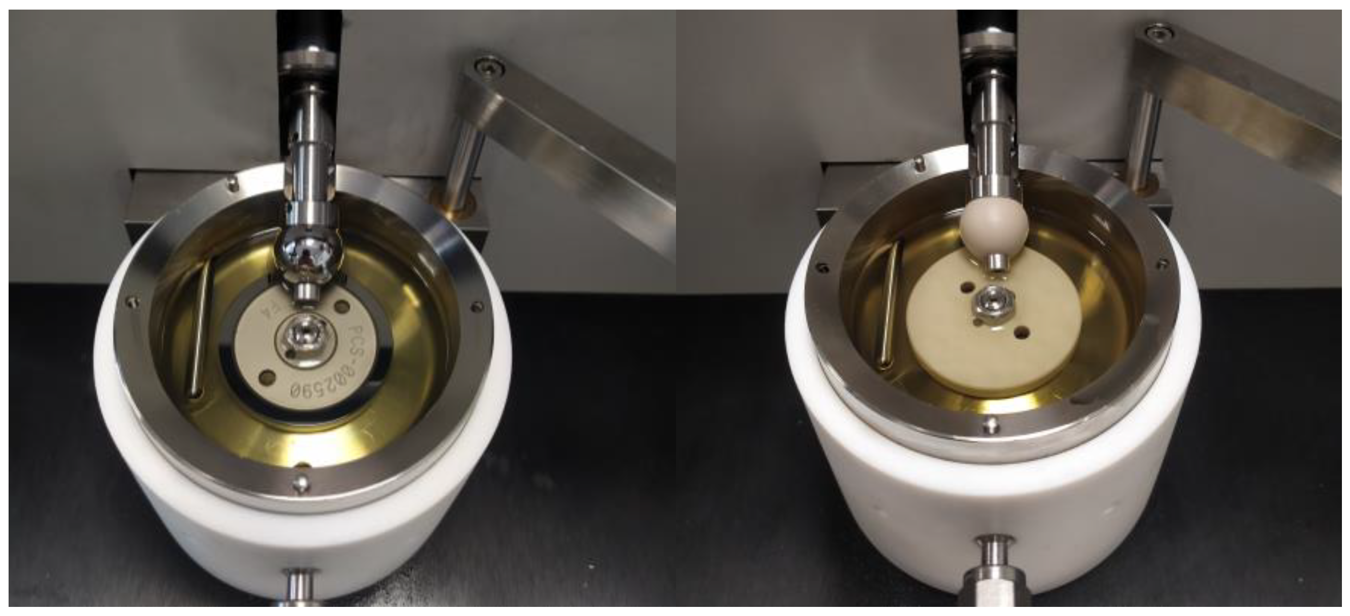
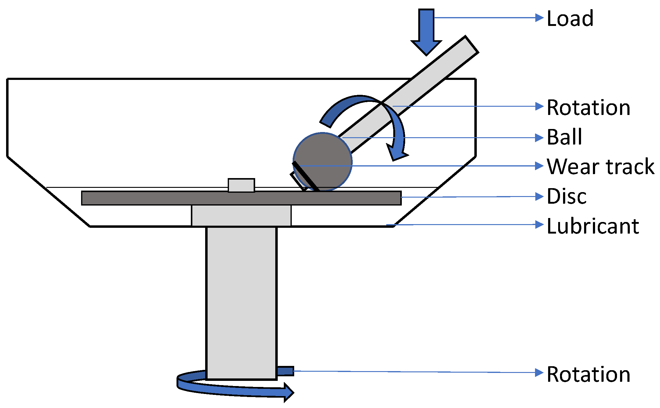
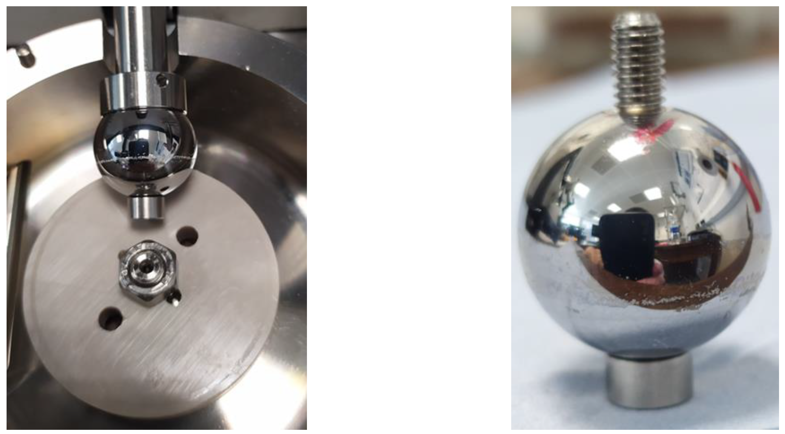
2.2. Tribological Method

According to the formation mechanism and characteristics of the lubricating film between contact surfaces, the lubrication regime can be divided into hydrodynamic lubrication, elastohydrodynamic lubrication (EHL) and mixed lubrication and boundary lubrication, as depicted in the so-called Stribeck curve (see Figure 2).
Keeping fixed the load and dynamic viscosity while varying the speeds is typical for a particular lubricated application. At high speeds, a contact operates in the hydrodynamic lubrication regime where an entrained liquid film completely separates the moving parts. Then, as the speed is reduced, mixed lubrication occurs when the liquid film thickness is of the same order of magnitude as the surface finish of the two bodies with the risk of contact. Finally, at very low speeds boundary lubrication occurs as the moving parts come into contact and the oil film is not sufficient to ensure separation of the moving parts.
The Stribeck curve illustrates how the coefficient of friction (CoF) is influenced by the viscosity of the lubricant, speed and load.
An assessment of the lubricant’s friction behavior under different regimes can be achieved using the Mini Traction Machine (MTM), crafted by PCS Instruments Ltd. Using this test equipment, the CoF is determined by rolling a steel ball on a rotating disc under conditions of EHD (Elastohydrodynamic) contact. Figure 3 displays this equipment, which is utilized to replicate different tribological test conditions by adjusting its operational parameters, such as load, entrainment speed, or the slide-to-roll ratio.
As this study mainly focused on the friction reducers effect on PEEK/steel counterparts, tribological tests were performed using three combinations of couplings: steel–steel, steel–PEEK and PEEK–steel, as shown in Figure 4.
Each test was carried out with new specimens after a cleaning phase. The cleaning phase consisted of a 1 h ultrasonic bath with toluene, followed by 5 min bath with isopropanol. The steel/PEEK balls were secured with an Allen-head screw and the discs fixed in place with a nut.
In the MTM equipment, the ball and the disc are operated independently to create a sliding and rolling contact (SRR). The SRR is defined as the ratio of the sliding velocity (udub) to the rolling velocity ((ud + ub)/2), where ud and ub are the velocities of the disc and ball relative to the contact. For the purpose of our experiment, this value was set at 50%. Load and temperature were kept constant for each run.
The entrainment speed was gradually reduced step by step, starting from the maximum value (2 m/s) down to a very low (0.02 m/s), thus building a Stribeck curve for each value of speed; the friction coefficient is calculated as the ratio between the measured traction force and applied load.
Stribeck curves were obtained at 40 °C, 80 °C and 120 °C—a temperature range selected as being representative of real operating conditions.
In addition to the Stribeck curve, the MTM can perform a conditioning phase, or “rubbing time”, where specimens are rubbed at a constant speed (0.02 m/s) for 120 min. Conditioning is important because on the one hand it simulates used oil and the ageing of the machinery in which the lubricant works. On the other hand, it allows the additives contained in the formulations to activate due to the high temperatures and low speeds of this part of the procedure.
Operating conditions for the Stribeck curve and conditioning profiles are reported in Table 3.
For each Stribeck curve measurement, the speed was kept constant and the friction values were averaged over 6 s. For the rubbing, the phase speed was kept constant and the friction values were averaged over 30 s. In both cases, the running-in period was 30 s.
Based on this, the performance of the lubricants with the different specimen material combinations was evaluated at low, medium and high temperature before conditioning, during conditioning and finally post-conditioning, as summarized in Table 4.
The wear profiles of the PEEK plates were measured with a stylus profilometer (Perthometer PGK from Mahr, Göttingen, Germany). The evaluation of the Stribeck curve involves not only analyzing the Coefficient of Friction (CoF) trends but also involves computing the area beneath the same curve using the trapezoid method, as described in references [41,42]. This integral result is known as the Stribeck Coefficient of Friction (SFC), which serves as a measure of energy dissipation. Low SFC values, characteristic of lubricants that minimize energy losses due to friction, correspond to excellent fuel economy performance. The reliability of the MTM test is demonstrated in Figure 5, where a commercially available grade 0W-20 SAE oil was subjected to testing twice under the conditions detailed in the paper. Each specimen material and lubricant sample underwent a repetition, with no data outliers being observed throughout the experimental campaign. Notably, these repetitions were conducted consecutively on the same day by the same operator. In the subsequent graphs, both test runs are presented, with the first run represented by a solid line and the second run by a dotted line, across all the selected temperatures.

3. Results

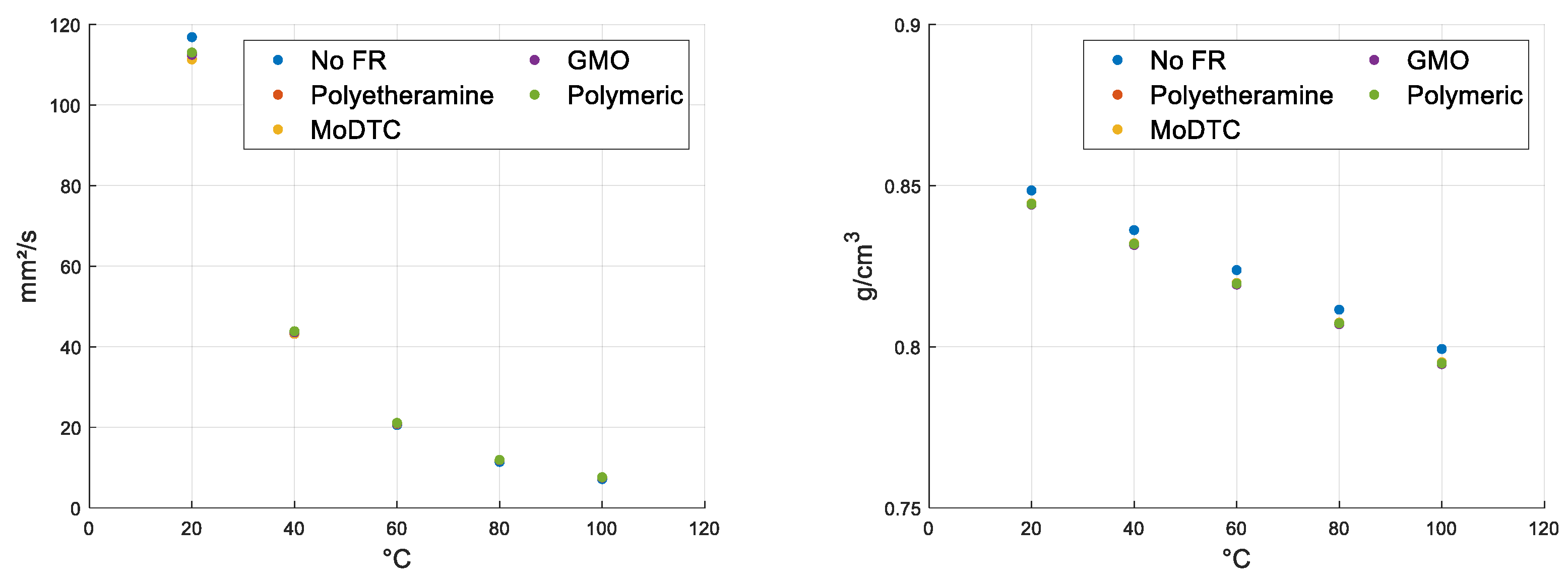
3.1. Rheological Characterization

Rheological measurements were carried out at 20, 40, 60, 80 and 100 °C (see Figure 6). The results show that the addition of the dispersants and friction reducers (amine, MoDTC, GMO and polymer) did not affect the properties of the base oil, in agreement with the theoretical prediction. Therefore, for the performance comparison we can consider all the formulations as isoviscous.
In regard to density, there are slight differences that can be assumed to be negligible.

3.2. Tribological Testing

3.2.1. Setup Phase: Dry Condition

Tests were conducted first under dry conditions. The dry test involved setting an entertainment speed of 400 mm/s (SRR 50%) and a load of 40 N at an ambient temperature for a duration of 60 min (following operating conditions in Table 5).
After each test, the specimens were analyzed using a Bruker confocal microscope and FTIR for wear and coating characterization.
Upon examining the images of the test specimens after the test (Figure 7), it was observed that polymeric material was deposited close to the wear track on the surface of the specimen ball (see Figure 8 and Figure 9). The test was concluded and the friction profile was observed to have initially increased during the running phase, followed by a rather thin curve (see Figure 10). From 15 min until the end of the test, the friction remained constant around an average value but became more dispersed, with sustained variation between the minimum and maximum, presumably due to wear and material transfer.
Fourier transform infrared spectroscopy (FTIR) is a technique used to identify chemical bonds in a molecule by producing an infrared absorption spectrum. In this study, FTIR (see Figure 11) was used to analyze the spectrum of the PEEK material transferred onto the steel ball (black line), the PEEK specimen inside the wear track (red line), and a new PEEK specimen (blue line).
The results showed that the material transferred onto the steel ball had all the characteristic peaks of polyether ketone in its spectrum. The dashed lines presented in the chart below are at 1249, 1314, 1428, 1510, 1613, 1662 cm−1 and are a typical chemical bond for the unfilled PEEK material. The figures 1662 and 1613 cm−1 are assigned to PEEK C=O stretching; 1510 cm−1 is the Ring vibration characteristic from benzene; 1314 cm−1 is the (C-C(=O)-C) bending; 1249 cm−1 is the C-O-C stretching. This is strong evidence for the formation of a tribofilm under the harsh conditions of the test.
In addition, Raman spectroscopy was employed for the characterization of the tribofilm. However, it was deemed unsuitable for this experiment and was discarded. Figure 12 illustrates that the spectrum of PEEK lacks identifiable peaks, whereas other materials, like PE, display multiple peaks in their footprint area, making them easily identifiable on different surfaces.
In order to simplify the study of tribofilm formation, an attempt was made to use the (3D-SLIM) imaging option (optical interferometry to measure sub-micron additive films) before defining the test procedure under lubricated conditions. Under dry conditions, as shown in Figure 13, the images before and after the test demonstrated a change in the test area, although with poor accuracy. However, in the lubricated tests, no noticeable change was observed. Consequently, this technique was discarded for the remainder of the experimental work.
The non-functioning of the slim technique can be explained in two ways. Firstly, PEEK may have an unsuitable refractive index. Secondly, under lubricated conditions the test is less extreme and tribofilm formation is less promoted, as shown in the pictures.

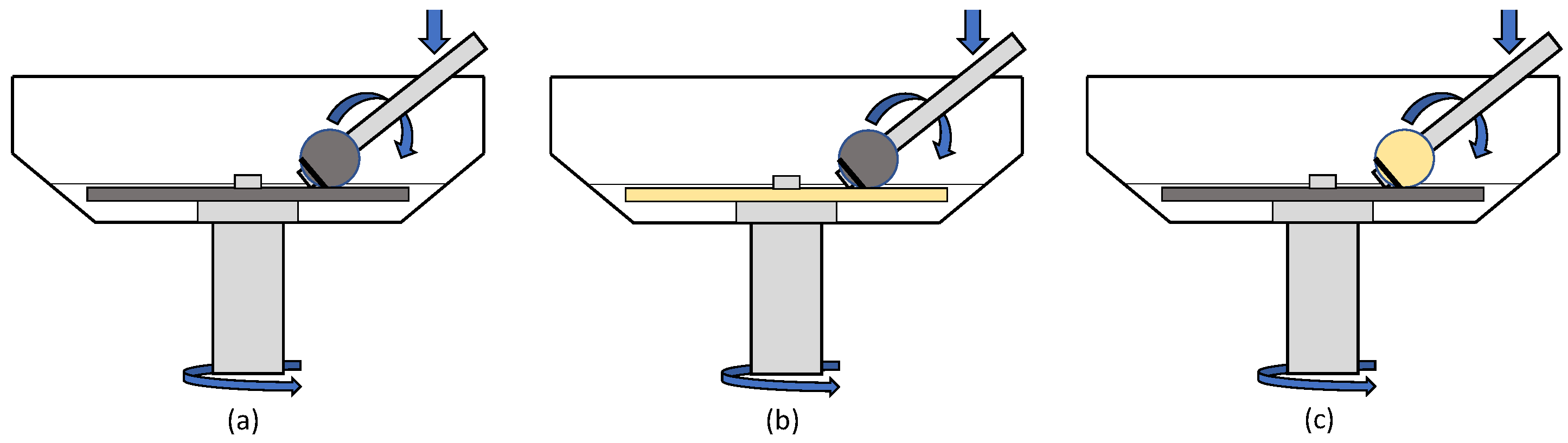
3.2.2. Steel–Steel Contact

The first case presented concerns the behavior of FRs in steel-on-steel contacts (ball and steel disc). At low T (40 °C), all curves show similar behavior, as the friction-reducing additives are not active. At 80 °C, the effect of MoDTC becomes evident in the mixed regime and through all speeds.
At high temperature (120 °C), the effect of the polymer is noticeable even at the highest speeds where the CoF profile becomes flat and reaches low CoF values (see Figure 14). These results are in line with those obtained in [42] using fully formulated products. Good behavior is evident also for the polyetheramine, while the GMO is the worst performing. Additionally, MoDTC exhibits good behavior.
The highest CoF curve belongs to the reference as it does not contain FR.
On the other hand, if one evaluates the lubricant samples during their conditioning, carried out at 120 °C and a constant speed (0.02 m/s) as shown in Figure 15, it can be assumed that the activation effect due to temperature is almost comparable (due to time and high temperature reasonably favoring kinetics); the only distinction is due to the mechanical/chemical interaction effect of the additives with the first surface layer. For No FR, MoDTC and polymeric, there is a decreasing trend that tends to stabilize after half an hour; for the other lubricants, the first point does not deviate much from the final value. For MoDTC and polymeric, there is a substantially beneficial effect throughout the conditioning part of the test, while for the other oils there is a negative effect compared to the reference.
Looking now at the friction profiles after high temperature conditioning (see Figure 16), we can see to a first approximation that the GMO, while before conditioning it had a similar performance to the base oil, now seems to have degraded and its behavior is worse. The ranking in terms of friction reduction remains the same as before conditioning, and the advantage over the non-additive oil is even more evident.

3.2.3. Steel–PEEK Contact

The second case is the combination of the steel ball and PEEK disc. Here, at medium temperatures, the friction reducers considered show no beneficial effect compared to the reference and all behavior is quite similar. The same tendency occurs at medium temperatures even at low speeds. With increasing temperature, the low-speed friction curve flattens out completely for the polymer additive sample, as seen in the case of steel-to-steel bearings. The other FR samples show lower CoF curves than the reference, but without significant differences (see Figure 17).
In conditioning, there is a strong dispersion (see Figure 18) because the PEEK disc has a tenfold rougher finish. All lubricant samples seem to behave better than the reference, from which one can deduce a preponderant material effect or a lower absorption capacity of the friction reducers.
Looking now at the friction profiles after high temperature conditioning shown in Figure 19, the advantages of friction reducers become more apparent. Here, it should be noted that, unlike the traditional steel–steel contact, there is a substantial decrease in friction even at high speeds.

3.2.4. PEEK–Steel Contact

The last case considered is the PEEK ball and steel disc coupling. Here, at low temperatures, as shown in Figure 20, the friction reducers studied show no beneficial effect compared to the reference oil. However, at medium temperatures, a reduction in friction is observed for FRs, especially at low speeds. In addition, the profiles appear to be flat and less affected by variable speed. With the increasing temperature, the positive effect of additives becomes evident at all speeds. The polymer curve not only flattens out, but at very low speeds it shows a downward trend.
In the rubbing phase, as illustrated in Figure 21, no dispersion occurs and all lubricant samples show curves of a flat nature with increased performance compared to the reference sample. This is in contrast to the results from the steel–steel coupling in which only two out of four friction-reducing additives were effective, and therefore suggests a synergistic effect between the FR and PEEK surface, possibly due to increased absorbance.
Looking now at the friction profiles after high-temperature conditioning, as shown in Figure 22, the advantages of the friction reducers are comparable to those before conditioning. A rapid chemical or mechanochemical reaction can be achieved and in these couplings, conditioning becomes less important and influential.
Finally, Friction comparisons before and after the conditioning phase are summarized in Figure 23.

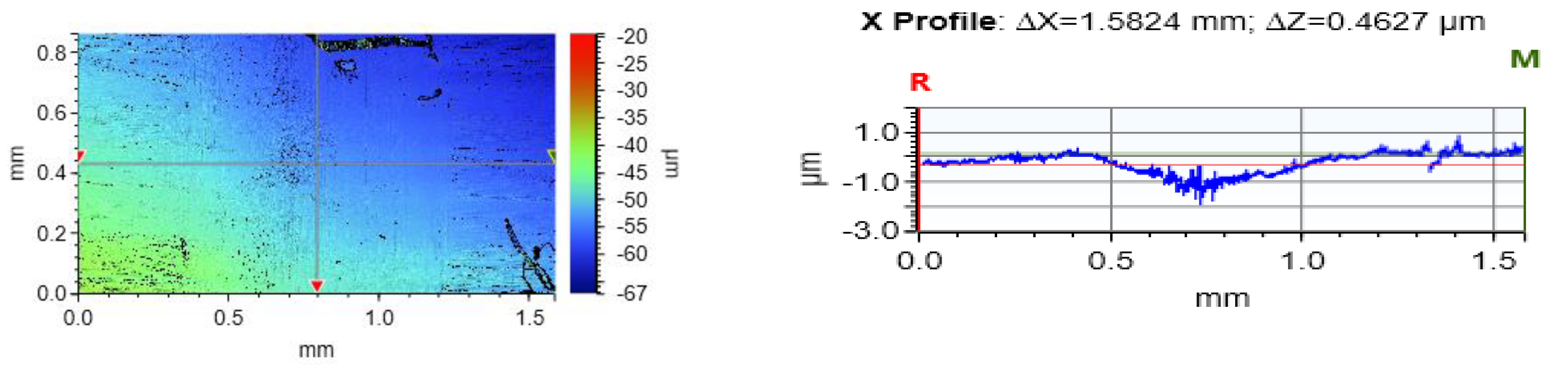
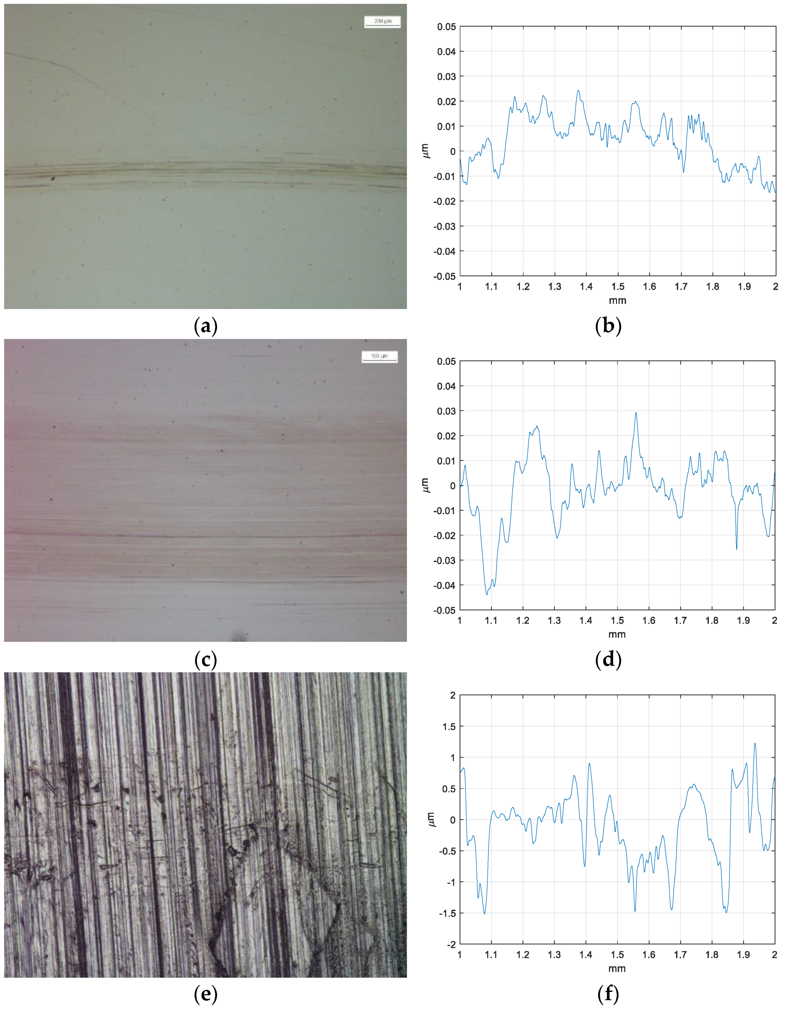
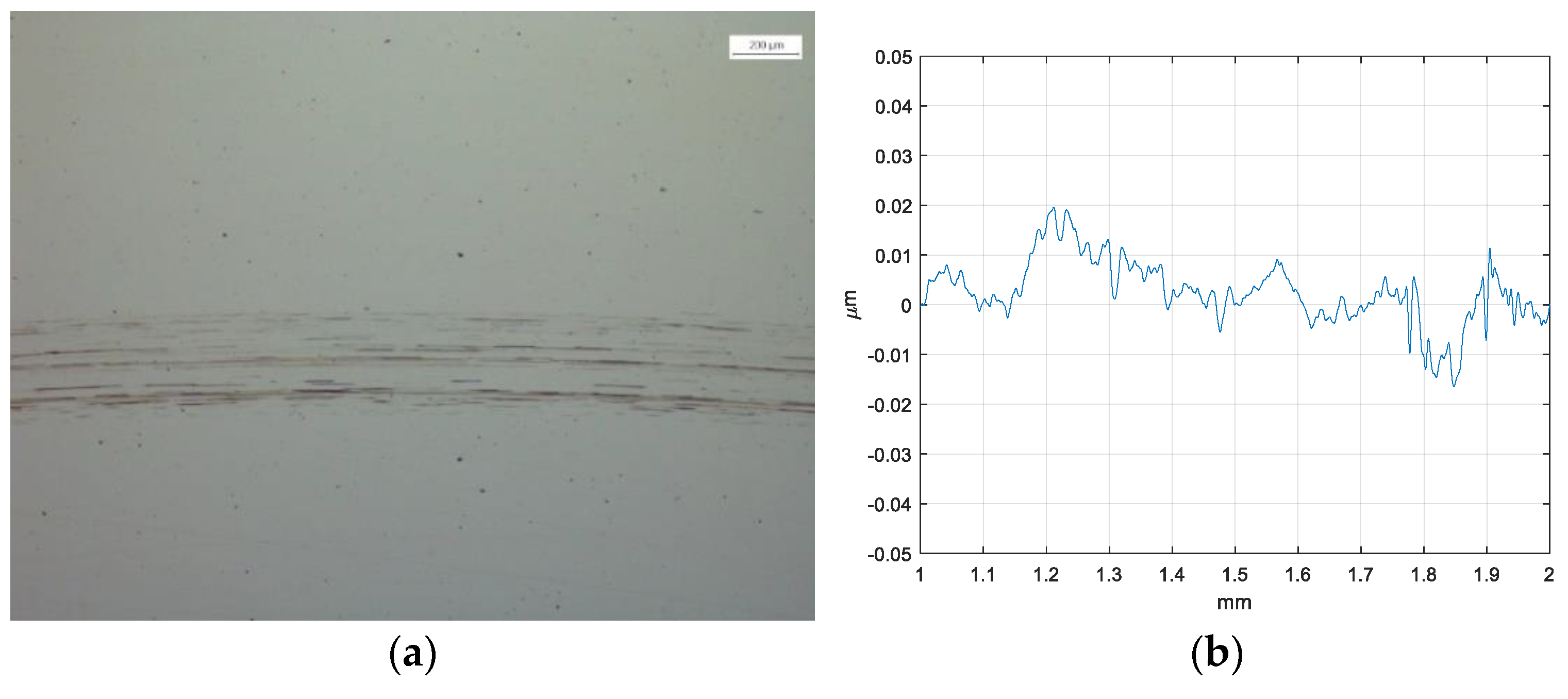
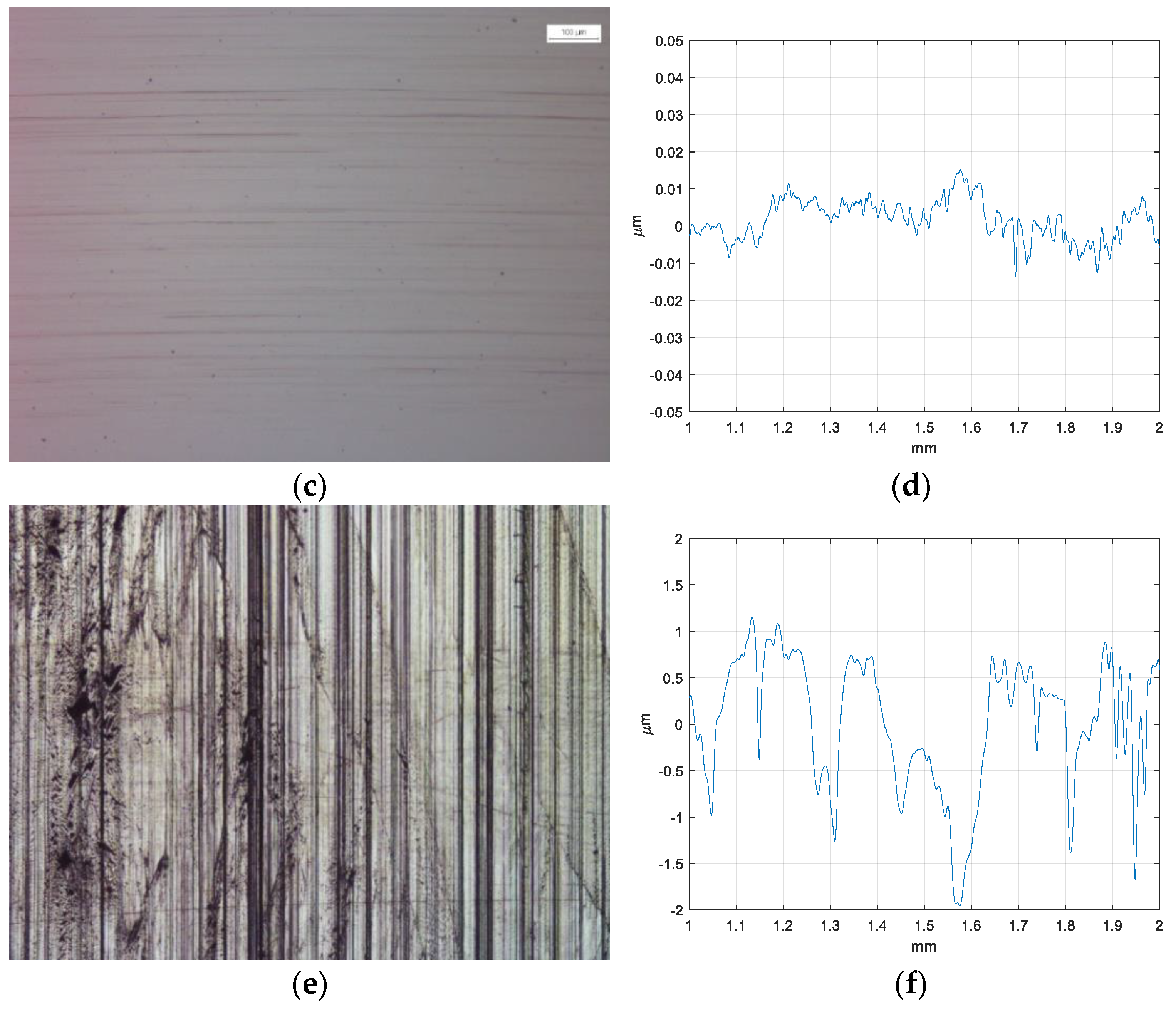
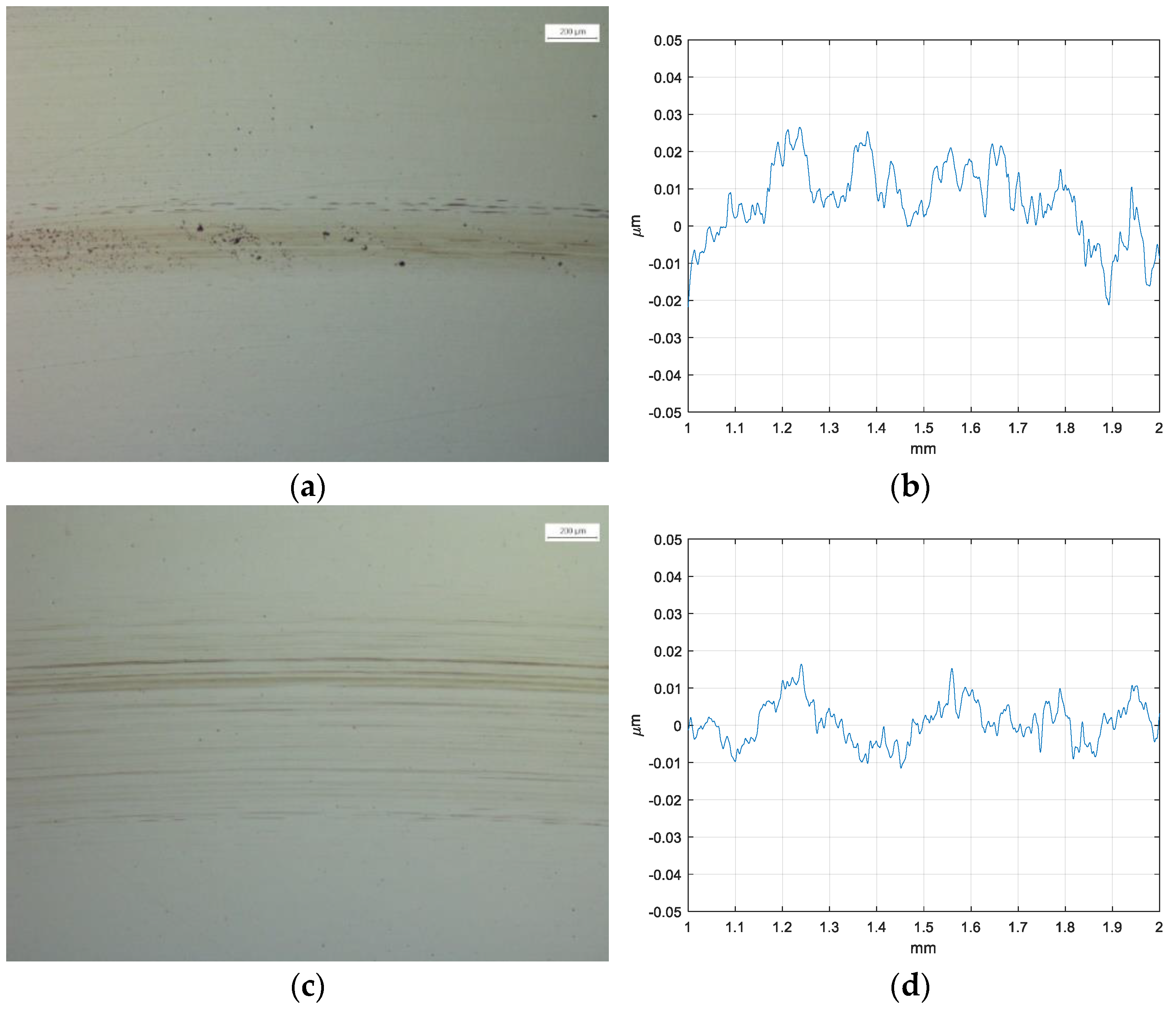
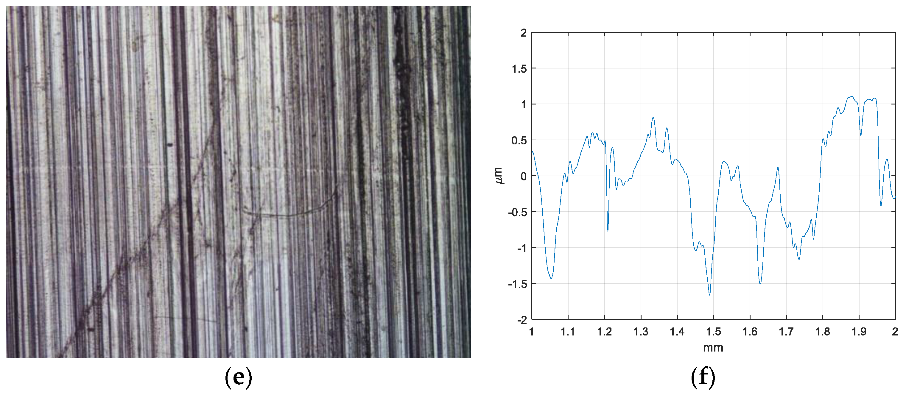
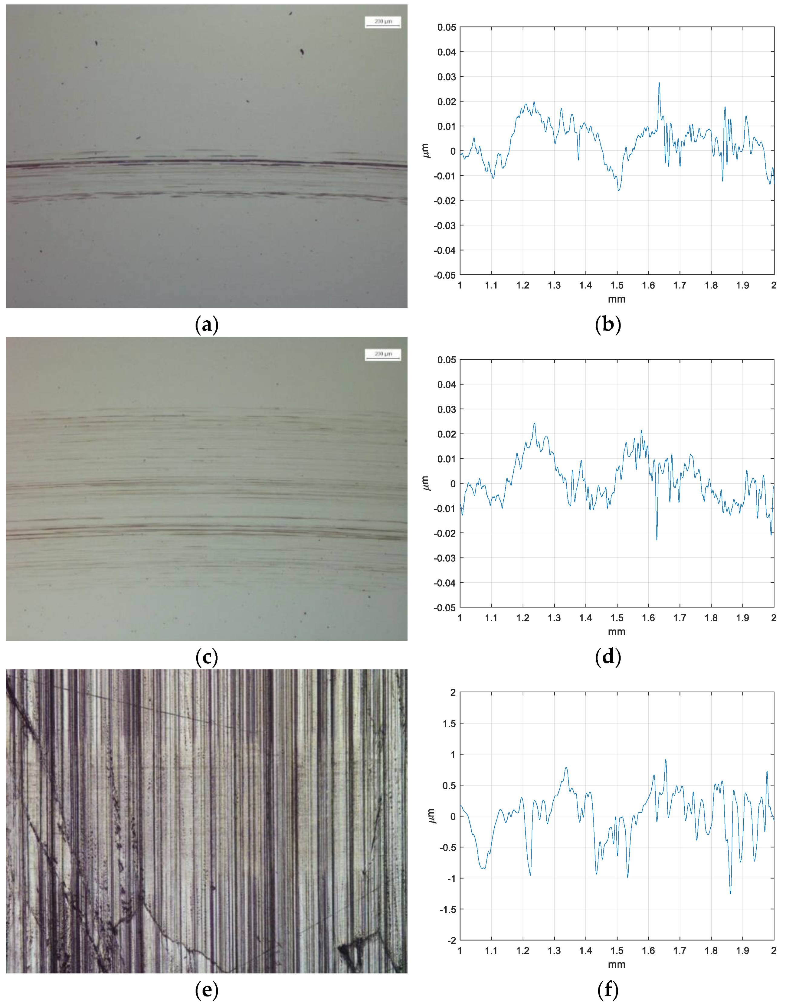
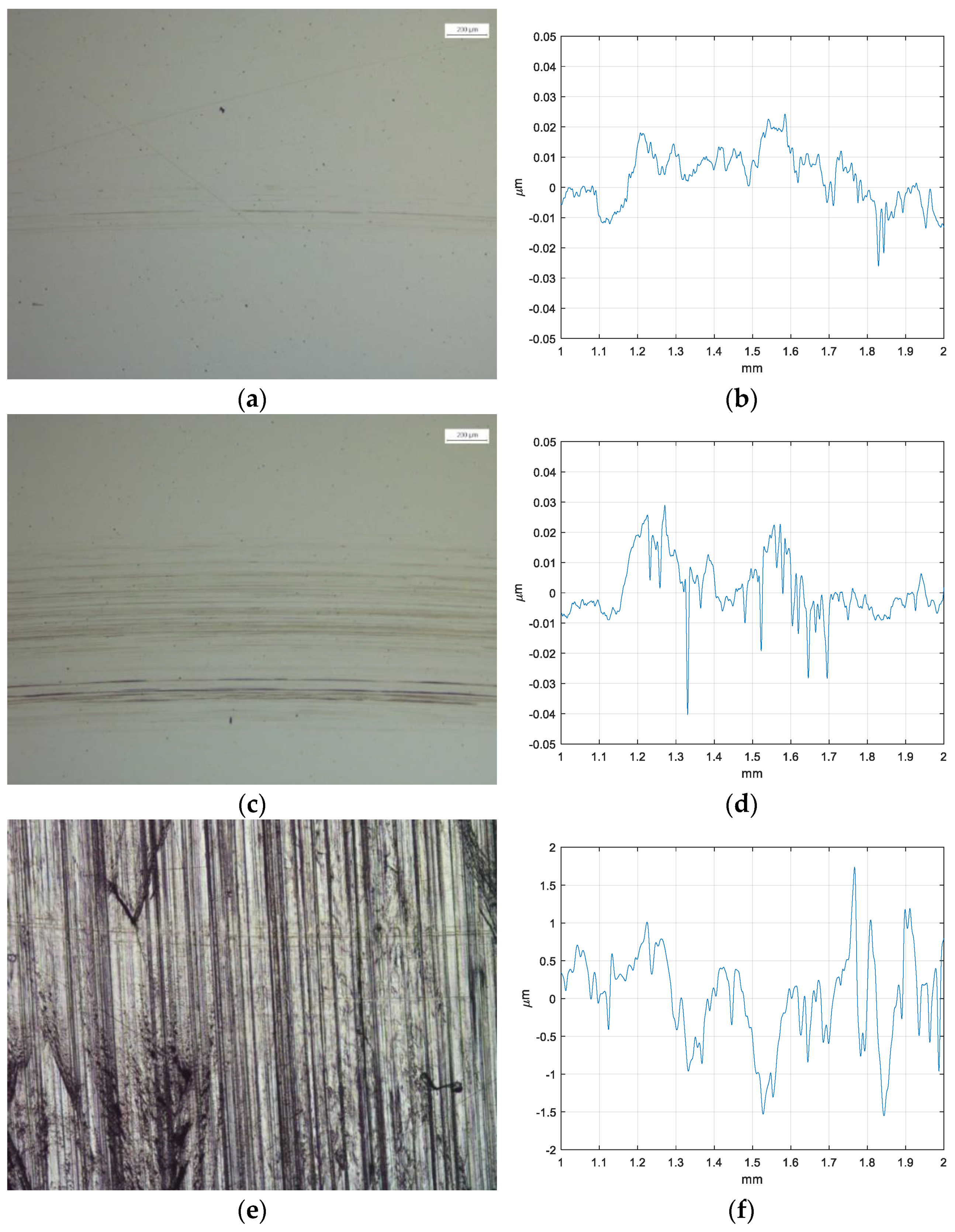
4. Wear Analysis: Microscope Images and Roughness Measurement

Microscope images and profilometer measurements of steel–steel, PEEK (ball)–steel, and steel–PEEK (disc) contacts are presented for different lubricants, including reference oil (see Figure 24), Polyetheramine (see Figure 25), MoDTC (see Figure 26), GMO (see Figure 27), and polymeric (see Figure 28).
From the results, it is difficult to differentiate wear in any of the contacts, but a distinct difference in surface finish can be observed between the steel specimens and the PEEK steel ones. There also appears to be a difference in the surface profile for the profile after the No FR test compared to the tests with the FRs present (the No FR profile is appreciably rougher). However, it is not possible to rank the lubricants as there is insufficient wear.

5. Discussion

This work has focused on FRs additives in non-conventional couplings. This showed that when the FMs additives are added in the base oil, a decrease in traction coefficient occurred. Furthermore, a synergistic effect demonstrated by observation that FRs show better performance in PEEK–steel contact than they do in steel–steel contact.
In contrast to [43] where MoDTC was added to an ester base oil, MoDTC has been shown here to work effectively when added to the Group III base oil in all coupling including steel–steel. According to [44], polymeric additive is the top performer in steel–steel coupling and the same ranking is maintained also in steel–PEEK and PEEK–steel couplings.
As Smeeth and Spikes observed in their work [44], when using an EHD machine at 80 °C there is a tribofilm growth for BO+FMs formulations compared to the reference one. The same trend was observed in our work and, as in [44], this is evident at low speed while the curves of all formulations collapse at the same value when the speed increases. At 120 °C, there is an evident gap between friction values for different samples even at higher speed.
While Tatsumi [38,39] attempted to elucidate the mechanism of tribofilm formation, our experimental work aimed to show the potential of friction reducers combined with conventionally marketed base oils (Mineral (Group III)) with special focus on non-conventional couplings under operating conditions very similar to those used in reality (higher temperature).

6. Conclusions

The study examined the impact of various friction reducers on the lubrication of steel–steel, steel–PEEK, and PEEK–steel contacts, with variations in temperature, in comparison to non-additive oil. The experimental procedure involved the utilization of the Stribeck curve and a conditioning phase followed by a high-temperature Stribeck curve.
The polymeric friction reducer outperforms all others in all three material combinations. This leads to the following insights:
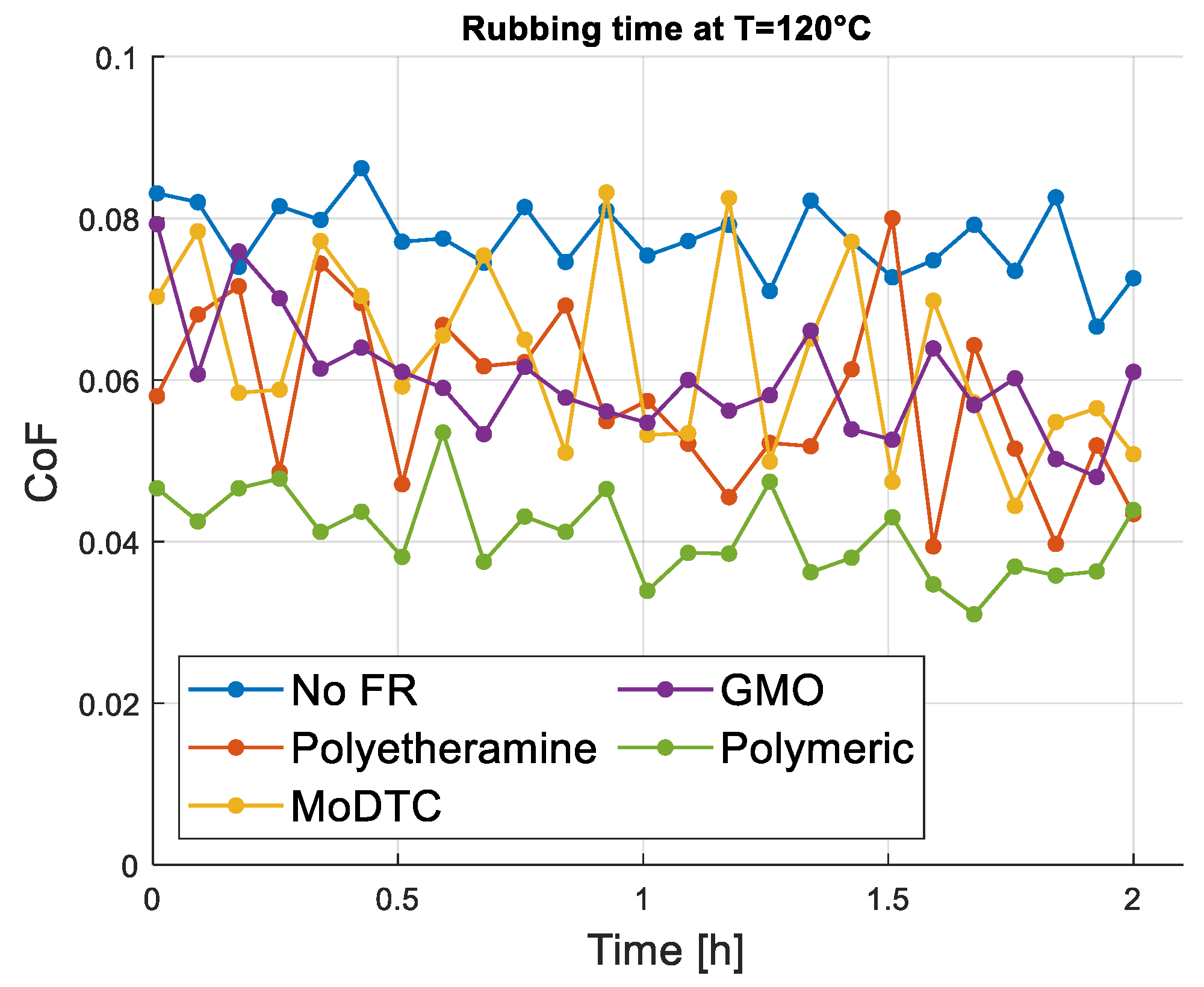
In steel-to-steel contact, GMOs exhibit a worse friction profile during and after preconditioning compared to the benchmark. However, when PEEK is involved, these effects are mitigated, likely due to a synergistic effect with PEEK or material dominance.
Differences are observed in PEEK-on-steel and steel-on-PEEK contact due to distinct tribofilm formation mechanisms and contact characteristics influenced by geometry and material type.
The PEEK ball deformation results in non-punctual contact with speed-independent, significantly higher friction, especially at high speeds. Conversely, a steel ball on a flat PEEK surface reduces friction due to non-punctual contact, PEEK disc deformation, and lower Hertzian pressure, particularly at high speeds.
In the PEEK ball coupling, material effects, especially at high temperatures, outweigh the contribution of each friction reducer in reducing CoF. MoDTC remains superior even in the presence of PEEK, with only minor differences from other anti-FR additives.
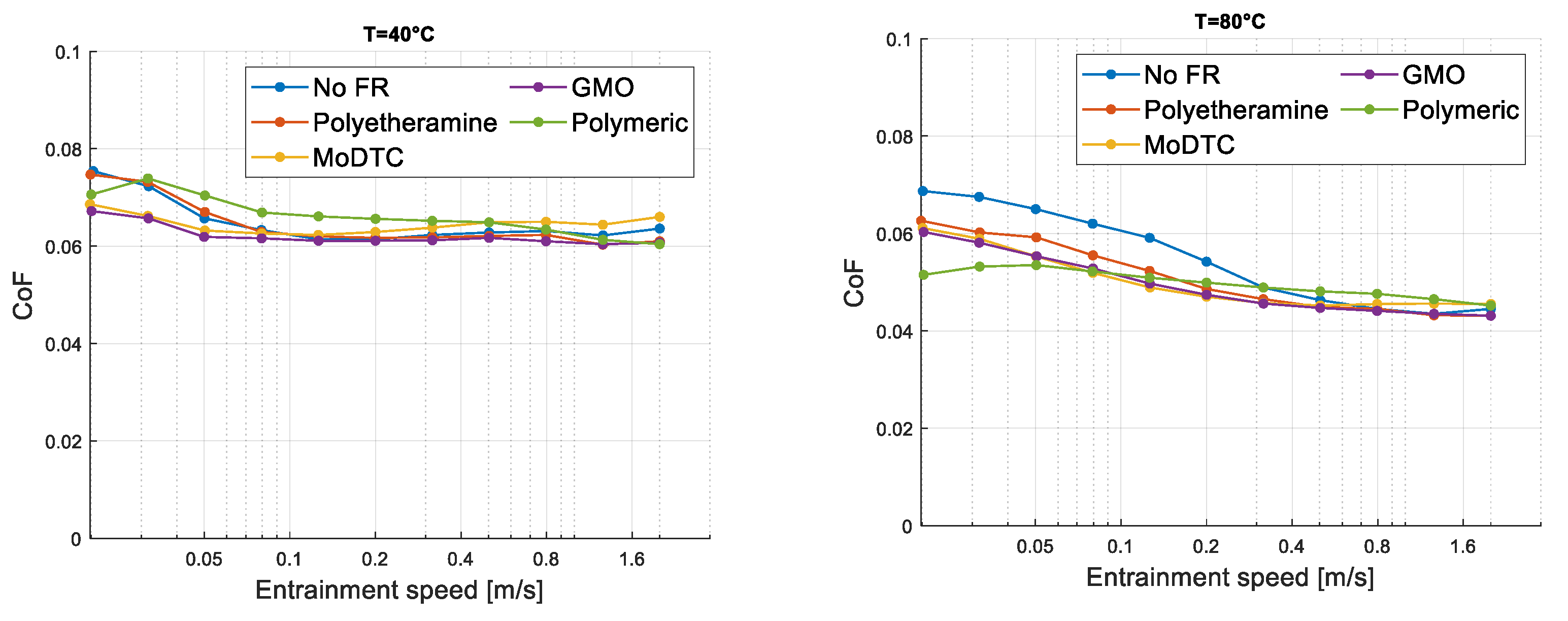
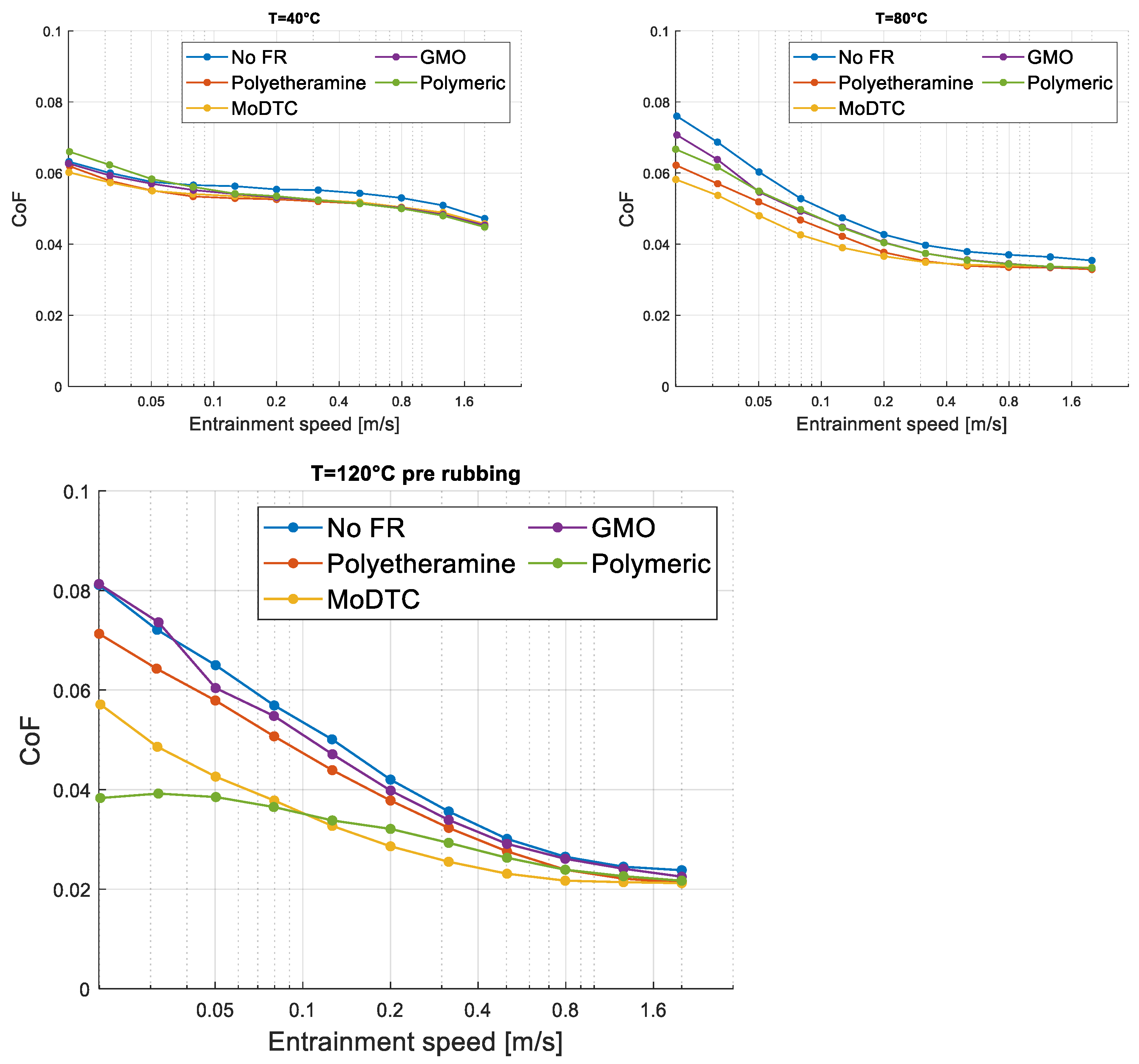
At low temperatures, all additives remain inactive, exhibiting friction profiles similar to non-additives.
At medium temperatures, reductions in friction are observed at speeds below 0.2 m/s for steel–steel contact, and this effect is more pronounced in PEEK-on-steel contact, especially with the polymeric reducer.
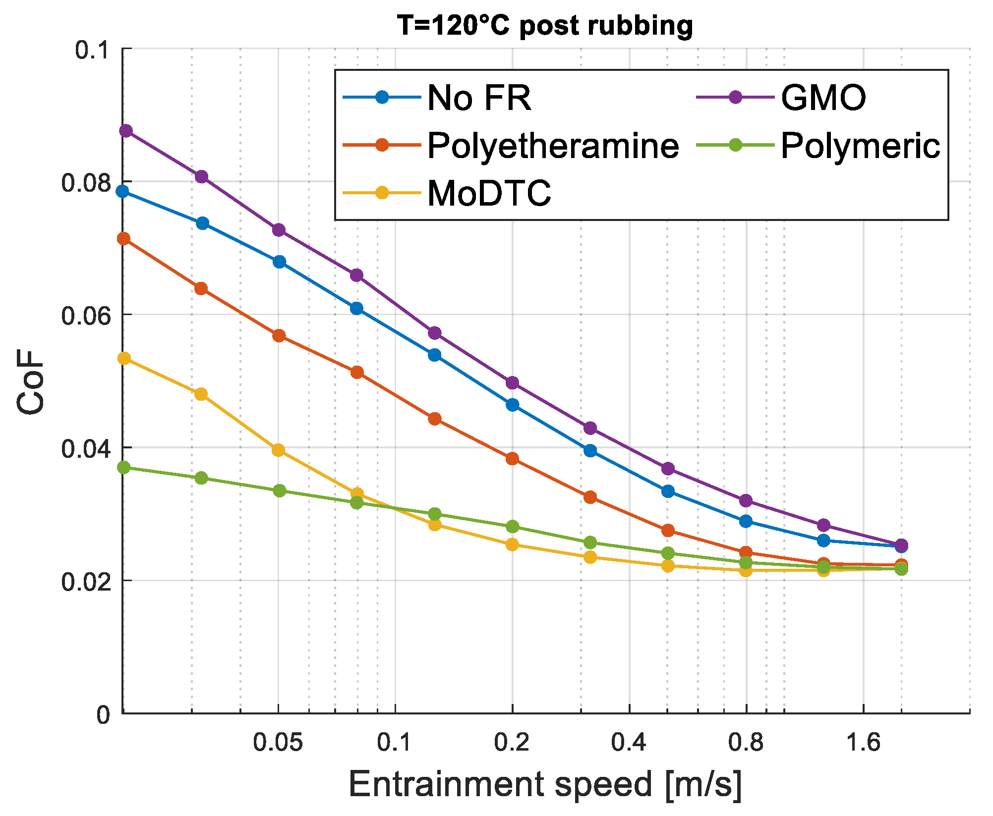
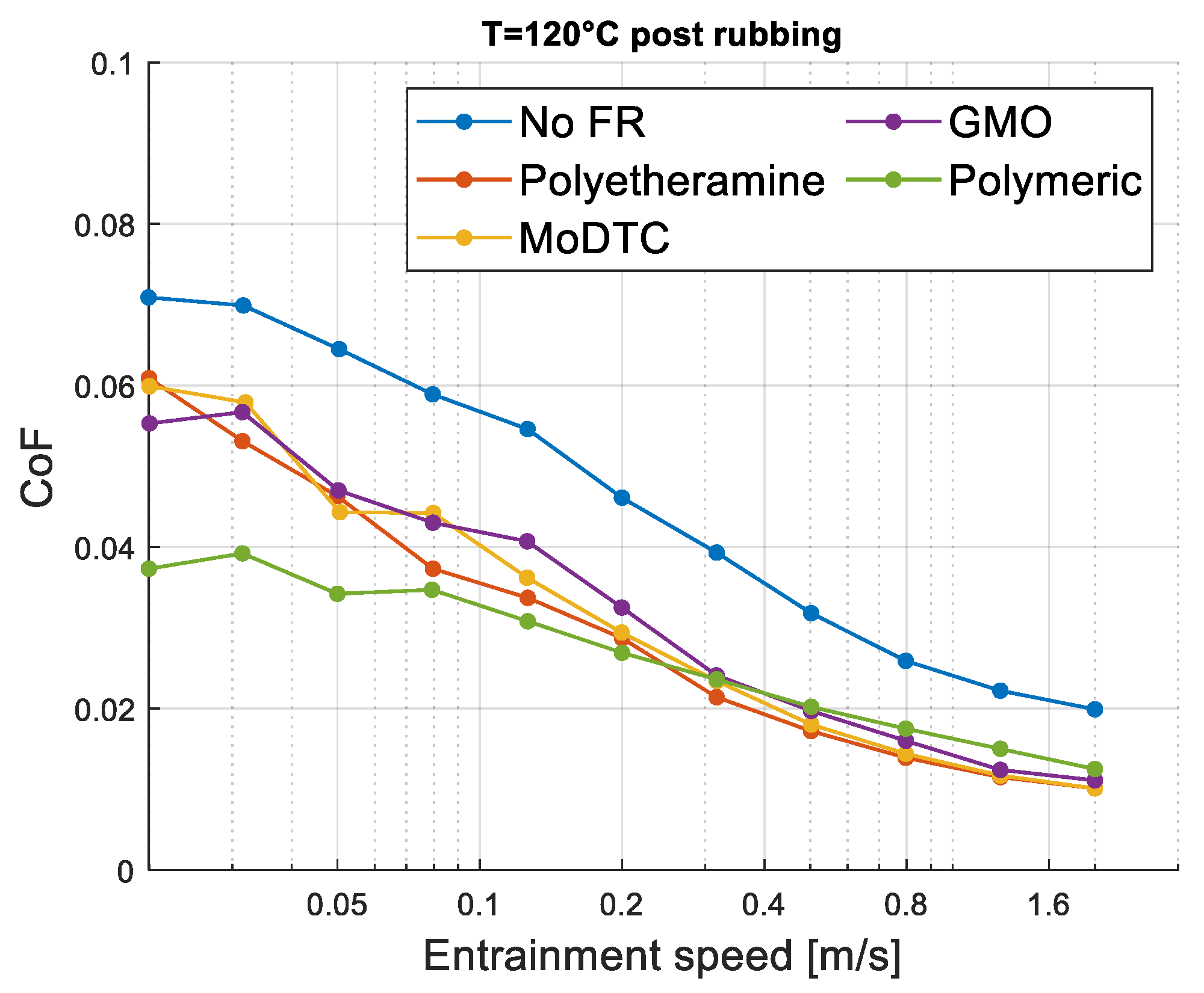
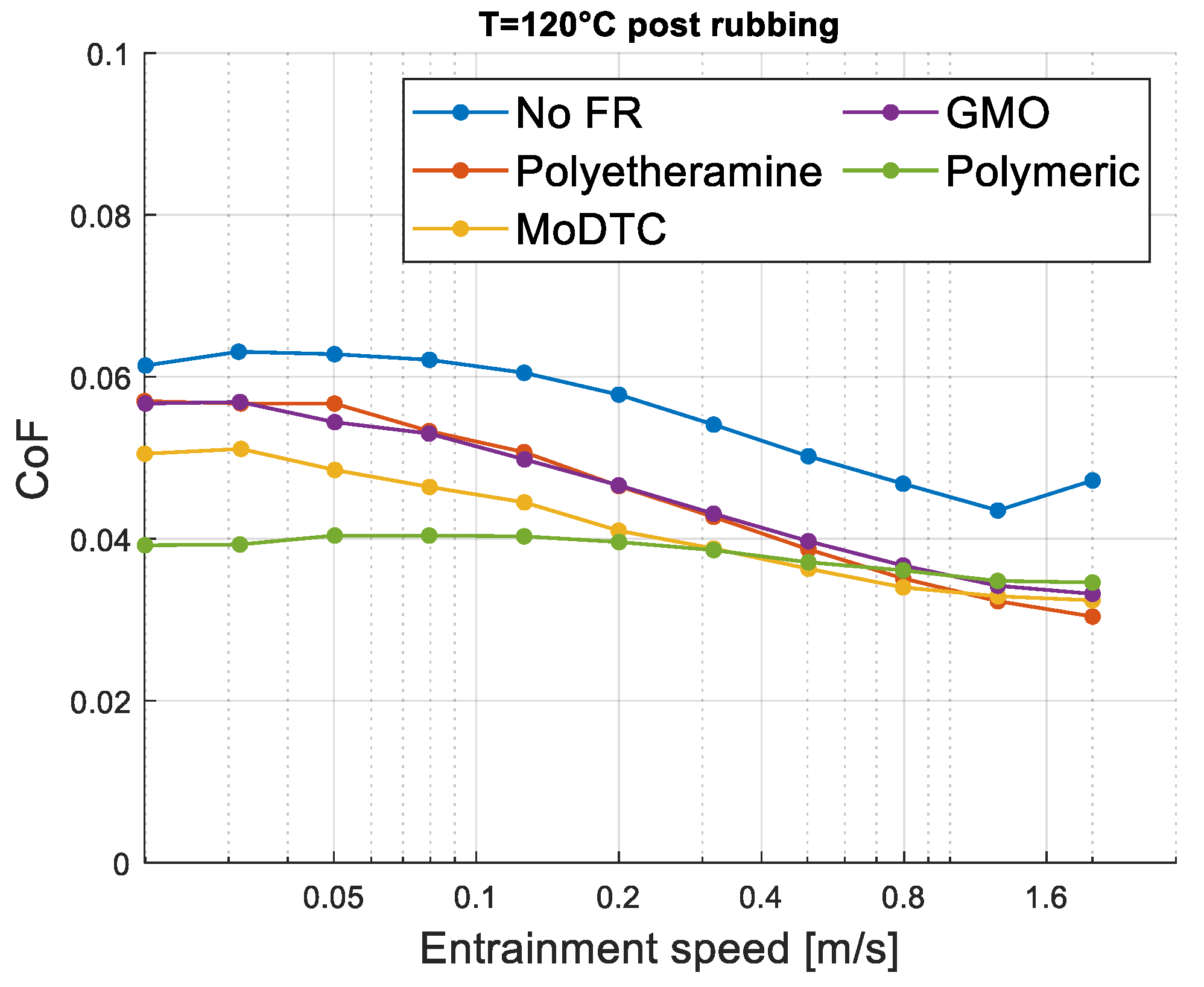
At higher temperatures with PEEK as a coupling, all friction reducers provide benefits compared to the reference “matrix.” In traditional steel–steel contact, GMO behaves similarly to the reference.
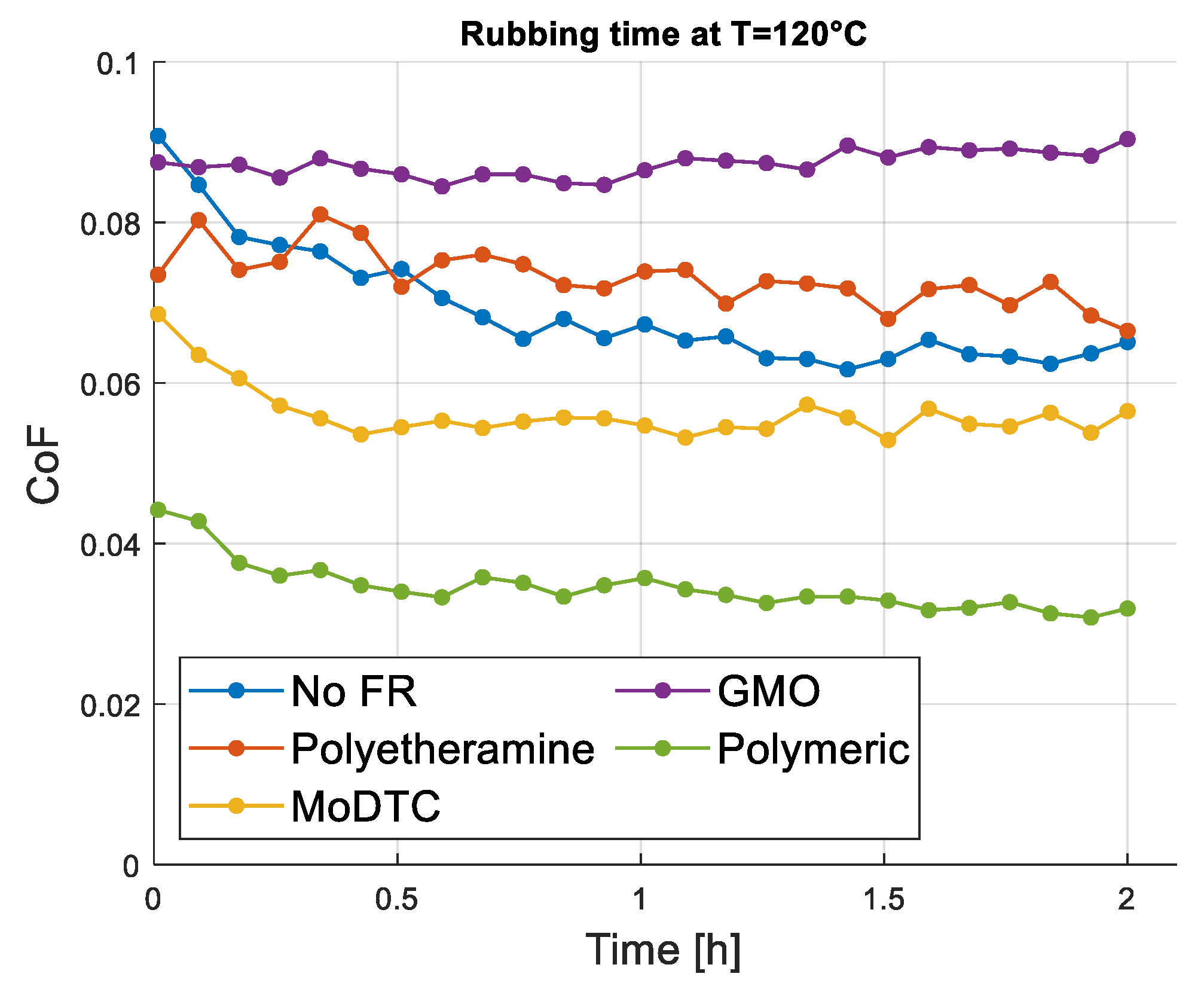
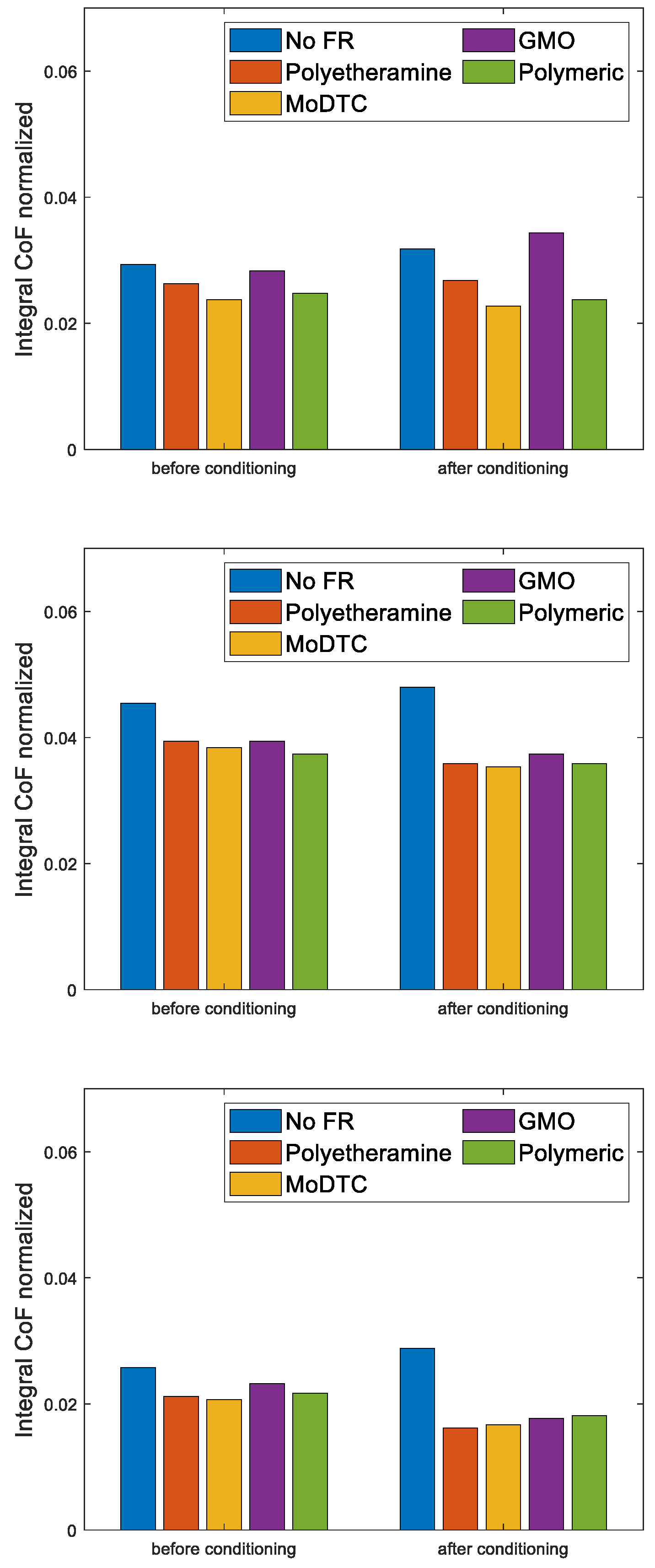
Comparing the top performing FR with the reference oil, there is a reduction in friction of 22%, 21% and 37%, respectively, in steel–steel, PEEK–steel and steel–PEEK couplings. In the standard steel–steel coupling, two out of four FRs did not reduce friction; however, after conditioning in the presence of PEEK all reducer additives performed well and increased the savings.
This study provides clarity on the impact of specific friction reducers on oil lubrication in PEEK–steel contact. The findings contribute to the design of efficient tribological systems and the formulation of suitable lubricants for PEEK–steel applications, promoting the adoption of green technologies in various future applications.
In future research, it is recommended to explore additional types of friction reducers. Furthermore, operational enhancements, such as new lubricant-aging procedures or the introduction of pollutants such as soot and water, could enhance evaluation robustness. Overall, this study emphasizes the role of PEEK in traditional machinery applications and the need to reduce CO2 emissions through lubricating oils for environmental reasons.

Author Contributions

Investigation & Writing—original draft, D.M.; Writing—review & editing, S.C.; Writing—review & editing, M.L.; Writing—review & editing, T.R.; Validation & Supervision, D.D.; Validation & Supervision, P.P. All authors have read and agreed to the published version of the manuscript.

Funding

This research received no external funding.

Data Availability Statement

The data-supported results are included within this article.

Acknowledgments

The present work was undertaken with the support of the Italian Ministry for Education, University and Research by means of the project Department of Excellence LIS4.0 (Integrated Laboratory for Lightweight e Smart Structures).

Conflicts of Interest

M.L. was employed by the company Eni SpA. The remaining authors declare that the research was conducted in the absence of any commercial or financial relationships that could be construed as a potential conflict of interest.

References

  1. Friedrich, K. Polymer composites for tribological applications. Adv. Ind. Eng. Polym. Res. 2018, 1, 3–39. [Google Scholar] [CrossRef]
  2. Myshkin, N.K.; Pesetskii, S.S.; Grigoriev, A.Y. Polymer tribology: Current state and applications. Tribol. Ind. 2015, 37, 284. [Google Scholar]
  3. Gandhi, R.; Jayawant, A.; Bhalerao, A.; Dandagwhal, R. Applicability of composite polymer gear in low RPM applications—A review. Int. J. Eng. Sci. Invent. 2018, 7, 36–41. [Google Scholar]
  4. Harrass, M.; Friedrich, K.; Almajid, A. Tribological behavior of selected engineering polymers under rolling contact. Tribol. Int. 2010, 43, 635–646. [Google Scholar] [CrossRef]
  5. Kurdi, A.; Kan, W.H.; Chang, L. Tribological behaviour of high performance polymers and polymer composites at elevated temperature. Tribol. Int. 2019, 130, 94–105. [Google Scholar] [CrossRef]
  6. Yeo, S.M.; Polycarpou, A.A. Fretting experiments of advanced polymeric coatings and the effect of transfer films on their tribological behavior. Tribol. Int. 2014, 79, 16–25. [Google Scholar] [CrossRef]
  7. Harris, K.L.; Pitenis, A.A.; Sawyer, W.G.; Krick, B.A.; Blackman, G.S.; Kasprzak, D.J.; Junk, C.P. PTFE Tribology and the Role of Mechanochemistry in the Development of Protective Surface Films. Macromolecules 1900, 48, 3739–3745. [Google Scholar] [CrossRef]
  8. Kurdi, A.; Chang, L. Recent advances in high performance polymers—Tribological aspects. Lubricants 2018, 7, 2. [Google Scholar] [CrossRef]
  9. Nunez, E.E.; Gheisari, R.; Polycarpou, A.A. Tribology review of blended bulk polymers and their coatings for high-load bearing applications. Tribol. Int. 2019, 129, 92–111. [Google Scholar] [CrossRef]
  10. Wang, Q.; Xu, J.; Shen, W.; Liu, W. An investigation of the friction and wear properties of nanometer Si3N4 filled PEEK. Wear 1996, 196, 82–86. [Google Scholar] [CrossRef]
  11. Minami, I.; Kubo, T.; Nanao, H.; Mori, S.; Iwata, H.; Fujita, M. Surface chemistry for improvement in load-carrying capacity of poly (ether-ether-ketone)-based materials by Poly (Tetrafluoroethylene). Tribol. Online 2008, 3, 190–194. [Google Scholar] [CrossRef]
  12. Greco, A.C.; Erck, R.; Ajayi, O.; Fenske, G. Effect of reinforcement morphology on high-speed sliding friction and wear of PEEK polymers. Wear 2011, 271, 2222–2229. [Google Scholar] [CrossRef]
  13. Kalin, M.; Zalaznik, M.; Novak, S. Wear and friction behaviour of poly-ether-ether-ketone (PEEK) filled with graphene, WS2 and CNT nanoparticles. Wear 2015, 332, 855–862. [Google Scholar] [CrossRef]
  14. Rodriguez, V.; Sukumaran, J.; Schlarb, A.K.; De Baets, P. Influence of solid lubricants on tribological properties of polyetheretherketone (PEEK). Tribol. Int. 2016, 103, 45–57. [Google Scholar] [CrossRef]
  15. Vickers, N.J. Animal communication: When I’m calling you, will you answer too? Curr. Biol. 2017, 27, R713–R715. [Google Scholar] [CrossRef]
  16. Lin, L.; Schlarb, A.K. Tribological response of the PEEK/SCF/graphite composite by releasing rigid particles into the tribosystem. Tribol. Int. 2019, 137, 173–179. [Google Scholar] [CrossRef]
  17. Sumer, M.; Unal, H.; Mimaroglu, A. Evaluation of tribological behaviour of PEEK and glass fibre reinforced PEEK composite under dry sliding and water lubricated conditions. Wear 2008, 265, 1061–1065. [Google Scholar] [CrossRef]
  18. Chen, B.; Wang, J.; Yan, F. Comparative investigation on the tribological behaviors of CF/PEEK composites under sea water lubrication. Tribol. Int. 2012, 52, 170–177. [Google Scholar] [CrossRef]
  19. Minn, M.; Sinha, S.K. The lubrication of poly (etheretherketone) by an aqueous solution of nattokinase. Wear 2012, 296, 528–535. [Google Scholar] [CrossRef]
  20. Zhang, G.; Wetzel, B.; Wang, Q. Tribological behavior of PEEK-based materials under mixed and boundary lubrication conditions. Tribol. Int. 2015, 88, 153–161. [Google Scholar] [CrossRef]
  21. de Andrade, T.F.; Wiebeck, H.; Sinatora, A. Tribology of natural Poly-Ether-Ether-Ketone (PEEK) under transmission oil lubrication. Polímeros 2019, 29. [Google Scholar] [CrossRef]
  22. Wu, C.; Wei, C.; Jin, X.; Akhtar, R.; Zhang, W. Carbon spheres as lubricant additives for improving tribological performance of polyetheretherketone. J. Mater. Sci. 2019, 54, 5127–5135. [Google Scholar] [CrossRef]
  23. Yu, G.; Liu, H.; Mao, K.; Zhu, C.; Wei, P.; Lu, Z. An experimental investigation on the wear of lubricated steel against PEEK gears. J. Tribol. 2020, 142, 041702. [Google Scholar] [CrossRef]
  24. Spikes, H. Friction Modifier Additives. Tribol. Lett. 2015, 60, 5. [Google Scholar] [CrossRef]
  25. Miller, A. The chemistry of lubricating oil additives. J. Chem. Educ. 1956, 33, 308. [Google Scholar] [CrossRef]
  26. Minami, I. Molecular science of lubricant additives. Appl. Sci. 2017, 7, 445. [Google Scholar] [CrossRef]
  27. Sniderman, D. The chemistry and function of lubricant additives. Tribol. Lubr. Technol. 2017, 73, 18–29. [Google Scholar]
  28. Bahadur, S. The development of transfer layers and their role in polymer tribology. Wear 2000, 245, 92. [Google Scholar] [CrossRef]
  29. Pradeepkumar, C.; Karthikeyan, S.; Rajini, N. A short review on the effect of transfer layer on tribological study of composite materials. Mater. Today Proc. 2022, 50, 2073–2077. [Google Scholar] [CrossRef]
  30. Laux, K.; Schwartz, C. Influence of linear reciprocating and multi-directional sliding on PEEK wear performance and transfer film formation. Wear 2013, 301, 727–734. [Google Scholar] [CrossRef]
  31. Myshkin, N.; Kovalev, A. Adhesion and surface forces in polymer tribology—A review. Friction 2018, 6, 143. [Google Scholar] [CrossRef]
  32. Raos, G.; Zappone, B. Polymer Adhesion: Seeking New Solutions for an Old Problem. Macromolecules 2021, 54, 10617–10644. [Google Scholar] [CrossRef]
  33. Jacobson, S.; Hogmark, S. Tribofilms—On the Crucial Importance of Tribologically Induced Surface Modifications; Research Signpost: Thiruvananthapuram, India, 2010; pp. 197–225. [Google Scholar]
  34. Shimizu, Y.; Spikes, H.A. The Influence of Slide–Roll Ratio on ZDDP Tribofilm Formation. Tribol. Lett. 2016, 64, 19. [Google Scholar] [CrossRef]
  35. Koshima, H.; Kamano, H.; Hisaeda, Y.; Liu, H.; Ye, S. Analyses of the adsorption structures of friction modifiers by means of quantitative structure-property relationship method and sum frequency generation spectroscopy. Tribol. Online 2010, 5, 165–172. [Google Scholar] [CrossRef]
  36. Lin, L.; Pei, X.-Q.; Bennewitz, R.; Schlarb, A.K. Friction and wear of PEEK in continuous sliding and unidirectional scratch tests. Tribol. Int. 2018, 122, 108–113. [Google Scholar] [CrossRef]
  37. Kurdi, A.; Wang, H.; Chang, L. Effect of nano-sized TiO2 addition on tribological behaviour of poly ether ether ketone composite. Tribol. Int. 2018, 117, 225–235. [Google Scholar] [CrossRef]
  38. Tatsumi, G.; Ratoi, M.; Shitara, Y.; Sakamoto, K.; Mellor, B.G. Effect of lubrication on friction and wear properties of PEEK with steel counterparts. Tribol. Online 2019, 14, 345–352. [Google Scholar] [CrossRef]
  39. Tatsumi, G.; Ratoi, M.; Shitara, Y.; Hasegawa, S.; Sakamoto, K.; Mellor, B.G. Mechanism of oil-lubrication of PEEK and its composites with steel counterparts. Wear 2021, 486, 204085. [Google Scholar] [CrossRef]
  40. Jean-Fulcrand, A. Transfer Layer Formation of High Performance Polymers, Polymer Blends and Polymer Composites; Imperial College London: London, UK, 2018. [Google Scholar]
  41. Lattuada, M.; Manni, M. Evolution of the Additive Technology for Top Tier Lubricating Oils: Use of Calixarene Detergents for Fuel Economy Improvement. In Proceedings of the Powertrains, Fuels & Lubricants Digital Summit, Virtual, 28–30 September 2021. SAE 2021-01-1212. [Google Scholar]
  42. Lattuada, M.; Manni, M. A New Methodology for the Experimental Evaluation of Organic Antifriction Additives; ISFL, International Symposium on Fuel and Lubricants: New Delhi, India, 2016. [Google Scholar]
  43. Cañellas, G.; Emeric, A.; Combarros, M.; Navarro, A.; Beltran, L.; Vilaseca, M.; Vives, J. Tribological Performance of Esters, Friction Modifier and Antiwear Additives for Electric Vehicle Applications. Lubricants 2023, 11, 109. [Google Scholar] [CrossRef]
  44. Smeeth, M.; Spikes, H.; Gunsel, S. Performance of viscosity index improvers in lubricated contacts. Langmuir 1996, 12, 4594–4598. [Google Scholar] [CrossRef]
Figure 1. Steel ball and steel disc (left side) vs. PEEK ball and PEEK disc (right side).
Lubricants 11 00487 g001
Figure 2. Stribeck curve and lubrication regimes.
Lubricants 11 00487 g002
Figure 3. MTM2 scheme.
Lubricants 11 00487 g003
Figure 4. MTM2 schematic configurations: (a) Steel–Steel, (b) Steel–PEEK, (c) PEEK–Steel.
Lubricants 11 00487 g004
Figure 5. Repeatability of MTM steel–steel tests for Stribeck curve profile from the top: at 40 °C, 80 °C and 120 °C.
Lubricants 11 00487 g005
Figure 6. Rheological properties of the oil tested: kinematic viscosity (left side) and density (right side).
Lubricants 11 00487 g006
Figure 7. From left: Specimens after dry test; Ball specimen detail after dry test.
Lubricants 11 00487 g007
Figure 8. From left: tribofilm on ball specimen; roughness profile of PEEK tribofilm on ball specimen.
Lubricants 11 00487 g008
Figure 9. From left: disc specimen; roughness profile of PEEK disc specimen.
Lubricants 11 00487 g009
Figure 10. CoF profile for dry test.
Lubricants 11 00487 g010
Figure 11. FTIR analysis after dry test.
Lubricants 11 00487 g011
Figure 12. From left: PEEK Raman spectrum; PE Raman spectrum.
Lubricants 11 00487 g012
Figure 13. From left: Before dry test; after 7 min dry; Before lubricated test; after 20 min.
Lubricants 11 00487 g013
Figure 14. Tests in steel–steel contact at low (top left), medium (top right) and high temperature (bottom).
Lubricants 11 00487 g014
Figure 15. Conditioning in steel–steel contact at high temperature.
Lubricants 11 00487 g015
Figure 16. Tests in steel–steel contact at high temperature after conditioning.
Lubricants 11 00487 g016
Figure 17. Tests in steel–steel contact at low (top left), medium (top right) and high temperature (bottom).
Lubricants 11 00487 g017
Figure 18. Conditioning in steel–PEEK contact at high temperature.
Lubricants 11 00487 g018
Figure 19. Tests in steel–PEEK contact at high temperature after conditioning.
Lubricants 11 00487 g019
Figure 20. Tests in PEEK–steel contact at low (top left), medium (top right) and high temperature (bottom).
Lubricants 11 00487 g020aLubricants 11 00487 g020b
Figure 21. Conditioning in PEEK–steel contact at high temperature.
Lubricants 11 00487 g021
Figure 22. Tests in PEEK–steel contact at high temperature after conditioning.
Lubricants 11 00487 g022
Figure 23. SFC divided by the speed range from top: steel–steel, steel–PEEK and PEEK–steel.
Lubricants 11 00487 g023
Figure 24. Reference oil test microscope image and profilometer measurement of disc specimen surfaces for (a,b) steel–steel contact; (c,d) PEEK–steel contact; (e,f) steel–PEEK contact.
Lubricants 11 00487 g024
Figure 25. Polyetheramine test microscope image and profilometer measurement of disc specimen surfaces for (a,b) steel–steel contact; (c,d) PEEK–steel contact; (e,f) steel–PEEK contact.
Lubricants 11 00487 g025aLubricants 11 00487 g025b
Figure 26. MoDTC test microscope image and profilometer measurement of disc specimen surfaces for (a,b) steel–steel contact; (c,d) PEEK–steel contact; (e,f) steel–PEEK contact.
Lubricants 11 00487 g026aLubricants 11 00487 g026b
Figure 27. GMO test microscope image and profilometer measurement of disc specimen surfaces for (a,b) steel–steel contact; (c,d) PEEK–steel contact; (e,f) steel–PEEK contact.
Lubricants 11 00487 g027
Figure 28. Polymeric test microscope image and profilometer measurement of disc specimen surfaces for (a,b) steel–steel contact; (c,d) PEEK–steel contact; (e,f) steel–PEEK contact.
Lubricants 11 00487 g028
Table 1. Mechanical properties of Steel and PEEK specimens.
MaterialCommercial NameYoung Modulus [GPa]Poisson’s Ratio [-]
SteelAISI 521002100.29
PEEK unfilledVITREX 450G3.80.33
Table 2. Lubricant formulations.
Lubricant NameKinematic Viscosity at 40 °C, cSt
No FR43.69
Polyetheramine43.20
MoDTC43.27
GMO43.58
Polymeric43.86
Table 3. MTM operating conditions.
MTM ParameterValue
Ball diameter, mm19.05
Nominal load, N40
SSR50%
(Stribeck) Entrainment speed, m/sFrom 2 to 0.02
(Stribeck) Temperature, °C40, 80, 120
(Stribeck) Duration, min5
Time duration for CoF calculation, seconds6
(Rubbing time) Entrainment speed, m/s0.02
(Rubbing time) Temperature, °C120
(Rubbing time) Duration, min120
Time duration for CoF calculation, seconds30
Table 4. Sequence of testing considered for the of FR effect on different material.
PhaseCurve TypeTemperature, °C
Low temperatureStribeck40
Medium temperatureStribeck80
High temperatureStribeck120
ConditioningRubbing time120
After ConditioningStribeck120
Table 5. MTM operating conditions of dry test.
Configuration and Lubricated ConditionPEEK on Steel in Dry Lubrication
Load40 N
Time duration60 min
Entertainment speed400 mm/s
TemperatureAmbient
Disclaimer/Publisher’s Note: The statements, opinions and data contained in all publications are solely those of the individual author(s) and contributor(s) and not of MDPI and/or the editor(s). MDPI and/or the editor(s) disclaim responsibility for any injury to people or property resulting from any ideas, methods, instructions or products referred to in the content.

