Article

Application of an Oleophobic Coating to Improve Formability in the Deep-Drawing Process

by
Sutasn Thipprakmas
1,*,
Juksawat Sriborwornmongkol
1,
Rudeemas Jankree
1 and
Wiriyakorn Phanitwong
2
1
Department of Tool and Materials Engineering, King Mongkut’s University of Technology Thonburi, 126 Prachautid Bangmod, Thungkru, Bangkok 10140, Thailand
2
Department of Industrial Engineering, Rajamangala University of Technology Rattanakosin, 96 Moo 3 Salaya, Phutthamonthon, Nakhon Pathom 73170, Thailand
*
Author to whom correspondence should be addressed.
Lubricants 2023, 11(3), 104; https://doi.org/10.3390/lubricants11030104
Submission received: 12 January 2023 / Revised: 15 February 2023 / Accepted: 18 February 2023 / Published: 27 February 2023

Abstract

:
The competition among sheet-metal-forming manufacturers in recent years has become more severe. Many manufacturers have survived by cutting their production costs. Increasing the formability, which could reduce the production costs, is the focus of many manufacturers and engineers. In the present research, to increase the formability over the limiting drawing ratio (LDR) in the cylindrical deep-drawing process, the application of oleophobic coating is proposed. An SUS304 (JIS standard)-stainless-steel cylindrical deep-drawn component was used as the investigated model. First, we applied the oleophobic coating in the sheet-metal-forming process, and tribology tests were carried out to examine the friction coefficients, which were reduced by approximately 60% compared with those of standard lubricant use (Iloform TDN81). Next, deep-drawing tests were performed to investigate the drawing ratio (DR). The LDR recommended in the past could be overcome, and it increased by approximately 12% with the oleophobic coating use. Finally, the deep-drawing mechanism using an extremely low friction coefficient was clarified as well. Based on these results, an oleophobic coating could be applied in the cylindrical deep-drawing process to increase the LDR. The results also clearly expose the multidisciplinary approach that combines an oleophobic coating application and the sheet-metal-forming process.

1. Introduction

In general, sheet-metal-forming operations, including bending, cutting, and deep drawing, are used to create practically all the sheet-metal goods used in the manufacturing sectors, such as the electronics, automotive, and office and home utensil industries. Numerous studies based on finite element method (FEM) approaches and experiments have been carried out to improve the quality of these sheet-metal products. Most studies on the bending process have concentrated on the spring-back characteristic as the principal impediment to controlling the size of bent pieces [1,2,3,4,5,6,7]. In terms of the cutting process, improvements in the cut-edge quality by reducing rollovers, cracks, and burrs have mainly been achieved [8,9,10,11,12,13,14]. In terms of the deep-drawing process, many studies have been performed to increase the deep-drawn-component quality by decreasing various defects, such as material thinning [15,16,17,18,19,20] and the earing defect [21,22,23,24,25]. Many researchers and engineers have also conducted their research based on experiments and FEM approaches to form intricately shaped deep-drawn components out of difficult-to-form materials, such as stainless steels and aluminum alloys [26,27,28]. However, in past studies, most of the researchers demonstrated the formability under the formability limitations (i.e., the limiting drawing ratio (LDR) in the case of cylindrical-shaped components, and the forming limit diagram (FLD) in the case of complicated-shaped components). Therefore, the increases in the formability over the LDR or FLD are still of interest and have been the focus in recent years. There are only a few studies that propose new techniques to increase the formability over the formability limitation [29,30]. Based on the deep-drawing theory, lubricant use can slightly increase the formability [31]. When lubricants with lower friction coefficients are applied, deep-drawn components with slightly higher formability can be achieved. However, the conventional lubrication uses in the deep-drawing process show a range of friction coefficients of approximately 0.05–0.15 [32,33,34,35]. The formability limitations in the past were based on these conventional lubricant uses. An oleophobic coating is an oil-repellent coating (i.e., it does not allow for the absorption of oil). An oleophobic coating is primarily used for making materials fingerprint-resistant, and in recent years, it has been extensively used to make smudge-resistant touchscreens for smart phones and tablets. It is also used in medical supplies and the consumer electronic industry, such as in medical tubing, endoscope lenses, and surgical visors [36,37,38,39,40]. The oil-repellent advantage could be applied to increase the formability in the deep-drawing process based on the extremely low friction coefficient (approximately 0.03). In previous research [30], the use of an oleophobic coating with an extremely low friction coefficient was first introduced for the sheet-metal-forming field, and it was partially used based on the zoning lubricant technique to increase the formability of a square cup. In the past, the advantage of the extremely low friction coefficient of an oleophobic coating was applied by using the difference in the friction coefficient of conventional lubricants to generate the balance in the material flow analysis on the flange section while the cup is drawn into the die. However, given the benefit of an extremely low friction coefficient, it is still interesting to investigate the use of an oleophobic coating without the zoning lubricant technique to overcome the formability limitations associated with conventional lubricant uses. In addition, in historical practical evidence, the reason that a reduction in the friction force improves the formability is not clearly explained, and the connection between the reduction in the friction force and the deep-drawing mechanisms to improve the formability are not entirely evident. Therefore, it is also interesting to use an oleophobic coating to examine the deep-drawing mechanisms related to the material flow analysis and friction force during deep-drawing operations. As the first step to investigate the feasibility of using only an oleophobic coating without the application of the zoning lubricant technique for the sheet-metal-forming process, in the present research, a cylindrical deep-drawn component was used as the investigated model. By using an oleophobic coating, the DR could be increased by approximately 12% over the LDR. Moreover, due to the extremely low friction coefficient, the use of an oleophobic coating clearly showed the effects of lubricant use on the deep-drawing mechanisms.

2. Experimental and FEM Simulation Procedures

2.1. Experimental Procedures

2.1.1. Tribology Tests

The disc had a 20 mm diameter and was constructed from SUS304 stainless steel. The ball had a 6 mm diameter and was manufactured from a SKD11 tool steel. In the current study, ball-on-disc tribology experiments were performed with three distinct lubricants: dry lubricant, standard lubrication, and an oleophobic coating. Iloform TDN81 (Castrol Limited, Pangbourne, UK), which is a standard lubricant, and Ultra-Ever Dry (Ultra-Ever Dry-store.eu, Liberec 13, Czech Republic), which is an oleophobic coating, were both utilized. In the case of a dry environment, there was no lubricant to prevent the ball from sliding on the disc. In the case of conventional lubricant use, the ball was forced to move down the disc with the continuous feeding of Iloform TDN 81. In the case of oleophobic coating use, the oleophobic-coated blank sheet was initially created and employed as a disc with a thickness of around 30 μm. Again, the ball moved across the disc with the continuous feeding of Iloform TDN 81. The normal load of 5 N was used to complete the tested sliding distance of approximately 50 m. In addition, to validate the set of 5 N normal loads, the contact pressure induced by the normal loads based on Hertz theory was also examined, and this value was compared to the contact pressure during the deep-drawing experiment. They were approximately 350 MPa. Table 1 contains a list of the additional testing conditions.

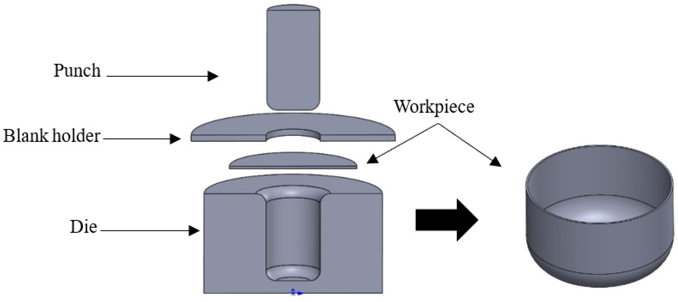
2.1.2. Deep-Drawing Experiments

A cylindrical cup with a 41.4 mm diameter, an 8.0 mm bottom radius, and a 0.5 mm thickness served as the study’s test model. SUS304 stainless steel was the material employed in this study. The LDR is the proportion of the largest starting blank diameter to the punch diameter when the drawn cup is produced without any cracks. Based on these data, the DR is roughly 1.93, which is similar to the LDR [31]. To evaluate the DR in the current study, initial blank diameters of 80.0 mm, 90.0 mm, and 100.0 mm were used. Particularly, the DRs were roughly 1.93, 2.17, and 2.41. The universal sheet-metal-testing machine, shown in Figure 1a, was the press machine used in the current study. Figure 1b also displays the punch and die sets that were employed. Because lubricant is supplied to the boundary between the tool and blank during the deep-drawing process, the surface roughness is another crucial process parameter. The hard chromium electroplating method was used to polish the surfaces of the punch, die, and blank holder. Table 1 reports the surface roughness of the tools, as well as a list of the deep-drawing-process conditions. The arithmetic average roughness (Ra) was investigated as the most widely used one-dimensional roughness parameter. The Ra measures the arithmetic average of the profile height deviations from the mean line. In addition, because the roughness of the tool is important for the feeding of the lubricant, the skewness roughness (Rsk), which measures the asymmetry of the profile about the mean line and indicates the predominance of the peak (Rsk > 0) or valley (Rsk < 0) structures that make up the surface, was also examined.

2.2. FEM Simulation Procedures

The deep-drawing process was simulated using the nonlinear FEM commercial code HyperForm 14.0 (Altair Engineering Inc., Troy, MI, USA), with RADIOSS script as the solver. Figure 2 depicts the researched model of a cylindrical deep-drawn component. The deep-drawing mechanism of conventional lubricant use was also researched based on the same model to comprehend the deep-drawing mechanism of oleophobic coating usage. Cimatron 3, which is commercial software, was used to produce these 3D cylindrical deep-drawing models, which were then imported as an IGES file into HyperForm. The components were meshed in HyperForm software. The mesh was produced using the HyperMesh preprocessor. Table 1 includes a list of the FEM simulation and experiment details. Because forming tools such as punches, dies, and binders are of the rigid type, the rigid R-Mesh was used to mesh them. The basic blank was divided into finite elements of the “shell” type and set as elastoplastic, and was then meshed using B-Mesh. A total of 3500 elements with four-node quadrilateral-shaped elements were produced. By using adaptive re-meshing, the combination of four-node quadrilateral-form components with triangular-shaped elements led to relatively clean meshes after re-mesh generation. To avoid deformations during deep drawing, the tool was meshed with the rigid mesh elements. During multistage formation analysis, data files from the prior stage are imported to the following stage for the subsequent analysis level. The results of the material flow and forming limit diagram were obtained by analyzing the output of the finite element simulation. The forming limit diagram (FLD) was utilized in this study to estimate the fracture zones on the deep-drawn components, and to clarify the forming characteristics. SUS304 stainless steel with a thickness of 0.5 mm was the workpiece used in this study. As the input parameters for the FEM modeling, the material properties of the flow curve equation and plastic strain ratio (R-value) were prepared. The constitutive equation was derived from the stress–strain curve using the results of the tensile test, and the workpiece material was modeled using an elastoplastic power-exponent isotropic-plasticity model of the Hollomon power law strain-hardening model. The strength coefficient and strain-hardening exponent are presented in Table 1 as 1209.4 MPa and 0.38, respectively, according to a previous study [30]. Next, a 0.55 mm clearance was established. Table 1 also lists the additional material requirements. The boundary conditions were specified with respect to the real process. The contact surface model in the current study was established with the Coulomb friction law, and friction coefficients (µ) of 0.03 for the use of an oleophobic lubricant and 0.10 for the use of a standard lubricant (Iloform TDN 81) were employed. The constant coefficient of this friction model is quite helpful in the analysis of many mechanical systems; however, it is not particularly useful in the simulation of the friction at the tool–workpiece interface in metal-forming operations. Wilson [41,42,43] has noted that a variety of different lubrication regimes can exist at the contact between the tool and workpiece. In most of them, the pressure of the bulk lubricant film carries all or a portion of the contact load. Only in the boundary regime do asperity contacts carry the load, and they also cause friction by shearing the boundary films. Even in this setting, the effective hardness of the asperities may be altered because of the high contact pressures and plastic substrate. The Amontons–Coulomb law fails because the real area of contact is no longer proportionate to the load. However, the precise experimental determination of the real contact area in sheet-metal forming is difficult due to the random nature of asperities. In addition, most of the efforts to create a better friction model for metal forming in the boundary regime have focused on [44]. However, there are issues with the estimation of the friction coefficient values. For these reasons, the literature on the friction coefficient in sheet-metal forming is focused on the Amontons–Coulomb rule.

3. Results and Discussion

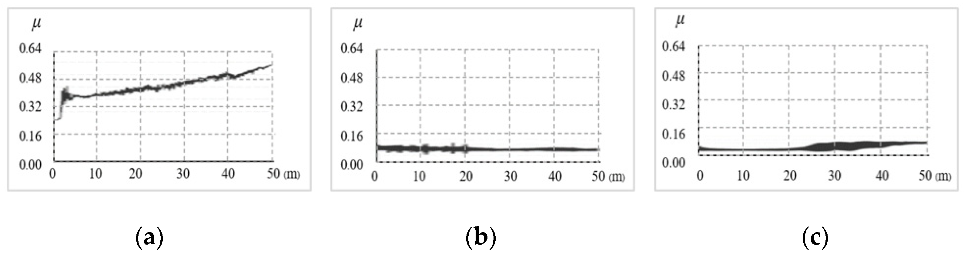
3.1. Friction Coefficient Examinations

The case with dry lubricant produced a friction coefficient of 0.40. This obtained friction coefficient was the same as those obtained in past studies [45]. Again, in the case of conventional lubricant use, the results showed that the friction coefficient could be decreased compared with that in the case of dry lubricant. Namely, it was decreased from 0.40 in the case of dry lubricant to 0.10 in the case of lubricant use, as shown in Figure 3b. In the case of oleophobic coating use, as shown in Figure 3c, because of the oil-repellent coating, the friction coefficient was the smallest. Specifically, when applying the Iloform TDN81 lubricant during the sliding of the ball on the oleophobic-coated disc, this lubricant contributed to the lubrication. However, oleophobic coating is an oil-repellent coating that does not allow for the absorption of the lubricant, and the spreading of the lubricant on the surface is also prevented, which results in the achievement of an extremely low friction coefficient. The friction coefficient was approximately 0.03 within the first sliding distance of 25 m, and it increased after the 25 m sliding distance. Owing to the ability of the oleophobic coating adhesion, it was easily torn off, and the friction coefficient increased to approximately 0.10 after the oleophobic coating was completely torn off when the sliding distance was approximately 50 m. However, this analysis indicated that the friction coefficient might have been extremely low when the oleophobic coating was applied, which is intriguing. These results could be used in the sheet-metal-forming process, in which the friction coefficient has a significant impact on the formability.

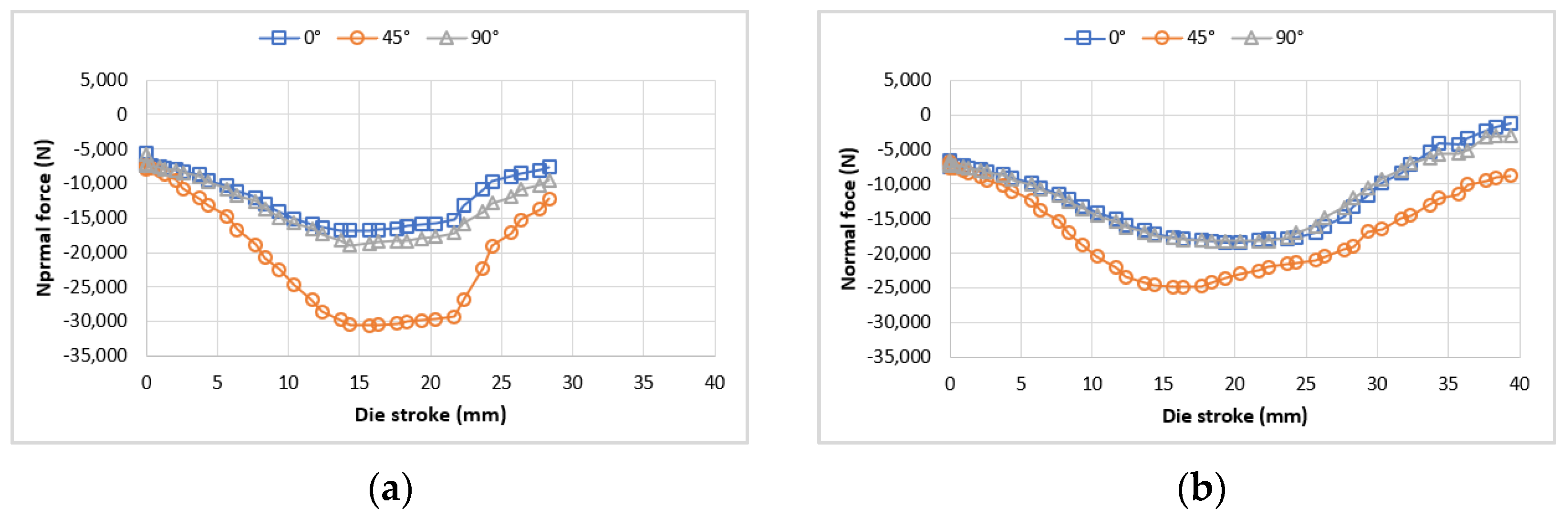
3.2. Analysis of Normal Force and Friction Force on Flange Portion during the Deep-Drawing Phase with Respect to Various Types of Lubricants

Utilizing a lubricant during the deep-drawing phase can lessen the force of the friction on the flange part, which increases the formability [31]. Additionally, by using a lubricant with a lower coefficient of friction, less friction force is generated on the flange piece, and higher formability is possible. In historical practical evidence, the reason that a reduction in the friction force improves the formability is not clearly explained, and the connection between the reduction in the friction force and the deep-drawing mechanisms to improve the formability is not entirely evident. According to the Coulomb friction law, the friction force is dependent on both the normal force and friction coefficient. In the deep-drawing process, the flange part experiences normal force during the deep-drawing phase. Additionally, because sheet metal is an anisotropic material, its mechanical property (R-value) has a major impact on the generation of normal force along the plane, at 45° and 90° from the rolling direction. The normal forces produced along the plane at 45° and 90° from the rolling direction were first set under the dry deep-drawing condition with a friction coefficient of 0.40, as illustrated in Figure 4a. This finding made it abundantly evident that there were differences between the normal forces created along the plane at 45° and 90° from the rolling direction, and that the generated normal forces were the lowest and highest along the plane and at 45° from the rolling direction, respectively, which is because the R-values were the smallest and largest, respectively. Next, in the event of lubricant use, as depicted in Figure 4b, the generated normal forces were the lowest and maximum, respectively, along the plane and at 45° from the rolling direction. However, the normal forces produced when a lubricant was used were less than those produced under dry deep-drawing conditions. Again, as seen in Figure 4c, the smaller normal force was produced when a lubricant with a lower coefficient of friction was used. In the case of standard lubrication uses (i.e., lubricants with friction coefficients of 0.1 and 0.05, as illustrated in Figure 4b,c, respectively), the variations in the normal force were relatively minor. In contrast, Figure 4d clearly illustrates how the use of an oleophobic coating with an extremely low friction coefficient caused a shift in the normal force. The difference in the generated normal force along the plane at 45° and 90° from the rolling direction also decreased when a reduced friction coefficient was used. The friction force was calculated by multiplying the normal force by the friction coefficient. Figure 5 displays the predicted friction force. Indeed, the predicted friction force in the dry-condition case was larger compared with those in the cases of the application of lower friction coefficients because of the substantial normal force generated in the higher-friction-coefficient applied case. We discovered that the difference in the friction force along the plane at 45° and 90° to the rolling direction could be decreased by decreasing the friction coefficient. As a result of this event, the friction force created in a circumferential direction became more uniform.
When the extremely low friction coefficient was used, this was amply demonstrated. In particular, when the extremely low friction coefficient was used, as shown in Figure 5d, the difference in the friction force along the plane at 45° and 90° from the rolling direction was significantly reduced, and the nearly uniform generated friction force in a circumferential direction was easily formed.

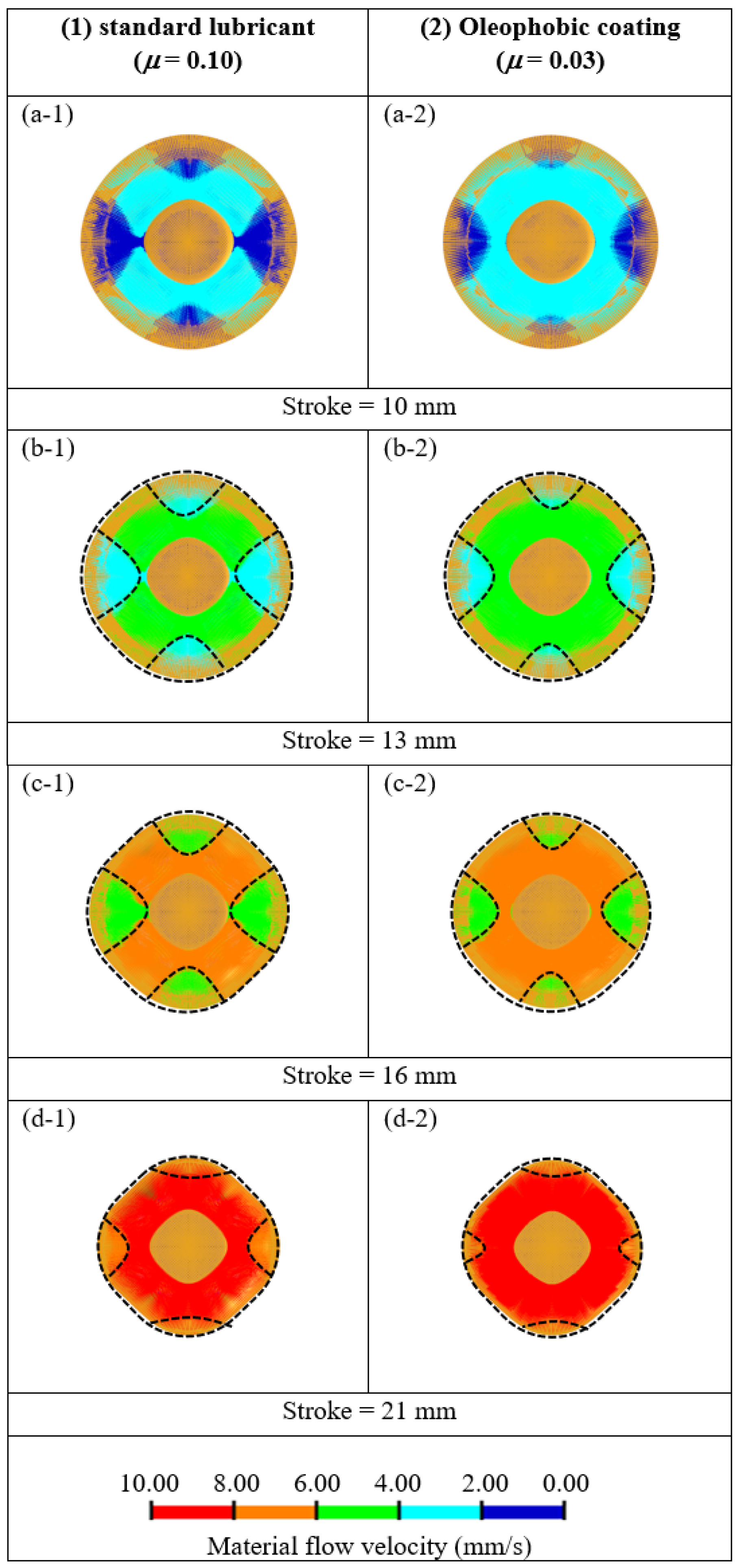
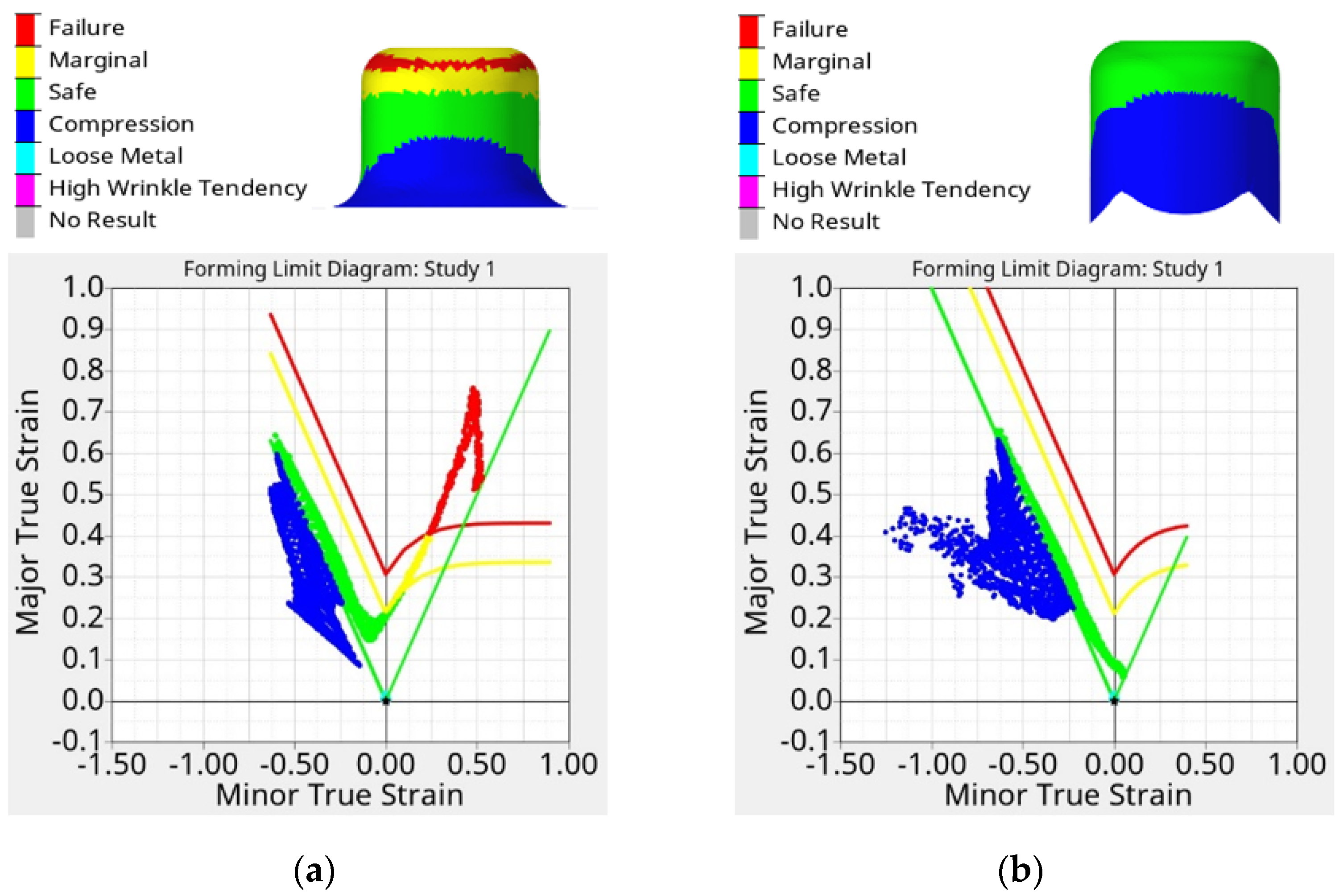
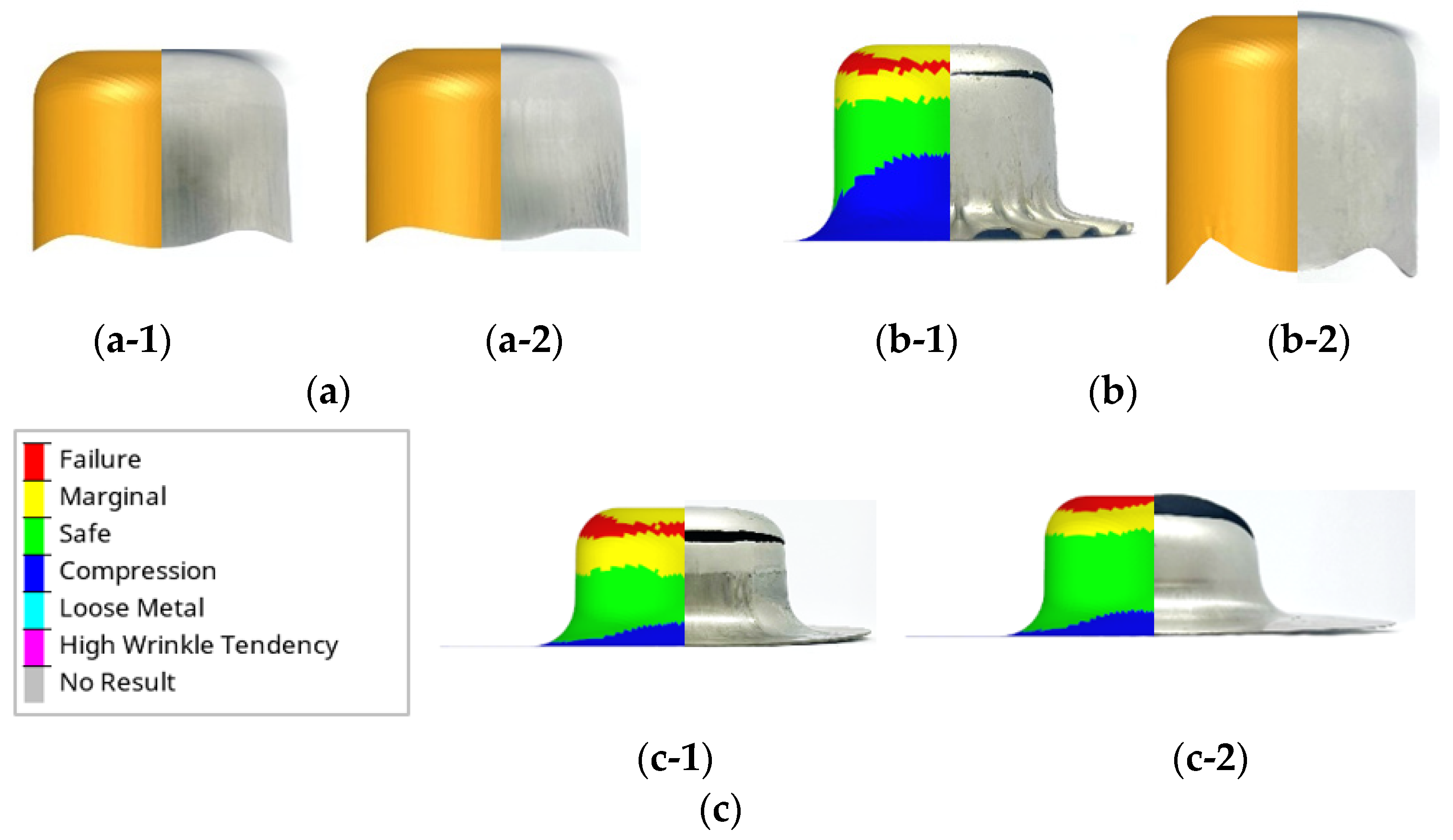
3.3. Comparison of Material Flow Analysis between a Standard Lubricant and Oleophobic Coating Applications

The normal force and friction force generated on the flange part during the deep-drawing phase were precisely described, as already mentioned. The varied material flow characteristics, particularly those in the flange portion during the deep-drawing phase, were caused by the different ways that the friction force with respect to the different friction coefficients was used. Figure 6 illustrates the material flow for applications using a standard lubricant and an oleophobic coating. The material flow for the roughly 10 mm deep-drawing stroke is shown in Figure 6a, revealing that both the standard lubricant and oleophobic coating applications followed the same pattern of material flow analysis. The effects of the friction force in each direction along the plane at 45° and 90° from the rolling direction on the material flow were amply demonstrated for a deep-drawing stroke of roughly 13 mm, as shown in Figure 6b. As seen by the dashed lines, the non-axisymmetric material flow on the flange was clearly demonstrated. In particular, the greater friction force was generated at 90° from the rolling direction, where it was more difficult to move the material. The effects of the friction force in each direction along the plane at 45° and 90° from the rolling direction on the material flow were established in the case of the standard lubricant application, as shown in Figure 6c. The material flow analysis became less circular. Although there was a slight variation in the friction force along the plane at 45° and 90° to the rolling direction, the application of the oleophobic coating, as shown in Figure 6(c-2), still resulted in a reduction in the non-axisymmetric material flow characteristic on the flange, and the asymmetry of the flange was amply demonstrated. A more rounded shape was used for the flange. The dashed lines clearly illustrate that the material flow on the flange was more circular in shape in the case of oleophobic coating use, as shown in Figure 6(c-2). The impacts of the friction force on the material flow in each direction along the plane at 45° and 90° from the rolling direction also grew stronger, as shown in Figure 6(d-1), in the case of the standard lubricant application. In the case of the oleophobic coating application, the non-axisymmetric material flow characteristic on the flange could be minimized, and the nearly axisymmetric material flow characteristic on the flange could be attained, as shown in Figure 6(d-2). Conversely, the application of the oleophobic coating once more exhibited the ability to consistently reduce the asymmetry of the flange, as well as the non-axisymmetric material flow characteristic on the flanges, as illustrated in Figure 6(d-2). These findings demonstrate that an oleophobic coating application can lessen the effects of the friction force along the plane at 45° and 90° to the rolling direction on the material flow during the deep-drawing process. The non-axisymmetric material flow feature on the flange could be reduced throughout the deep-drawing process, and the flange’s form became rounder. As a result, it was possible to boost the LDR and avoid cup-wall thinning and fracture.

3.4. Examination of Material Flow Analysis with Respect to Drawing Ratios

To clearly clarify the effects of the material flow analysis on the flange portion with respect to the drawing ratios, an LDR of the stainless steel with lubricant use of approximately 1.93 was investigated [31]. Drawing ratios of 2.41 (initial blank diameters of 100 mm), which were larger than the LDR, were investigated, in addition to a drawing ratio of 2.17 (initial blank diameters of 90 mm), which is shown in Section 3.3. In the case of a DR of 1.93, as shown in Figure 7a, owing to the small initial blank diameter used, the results showed the somewhat same manner of material flow analysis on the flange portion in the initial deep-drawing phase in the cases of the standard lubricant and oleophobic coating applications, as shown in Figure 7(a-1),(a-2), respectively. As the deep-drawing stroke increased, we observed differences in the material flow analysis on the flange portion between the cases of standard lubricant and oleophobic coating applications, as shown in Figure 7(a-3),(a-4), respectively. Specifically, compared with the standard lubricant application, the non-axisymmetric material flow characteristic on the flange could be reduced and was more uniform during the deep-drawing process in the case of the oleophobic coating application. These characteristics were more clearly observable as the deep-drawing stroke increased, as shown in Figure 7(a-5)–(a-8). However, according to the results, the deep-drawn components could only be successfully formed in the case of the oleophobic coating application, as shown in Figure 8b, and vice versa, where cracks formed on the deep-drawn component in the case of standard lubricant use, as shown in Figure 8a.
The results also confirmed that, due to the fact that the nonuniform material flow characteristic on the flange could be reduced and the material flow analysis was more circular in shape during the deep-drawing process in the case of the oleophobic coating application, the risk of fracture occurrence in the case of the oleophobic coating application was lower than that in the case of the standard lubricant application, as shown in the FLDs in Figure 8. In the case of a DR of 2.41, as shown in Figure 7b, owing to the large initial blank diameter used, the results showed the same manner of material flow analysis on the flange portion in the initial deep-drawing phase in the cases of standard lubricant and oleophobic coating applications, as shown in Figure 7(b-1),(b-2), respectively. However, compared with a DR of 1.93, the nonuniform material flow characteristic on the flange was larger and the circular shape of the material flow analysis was smaller during the deep-drawing process, which also meant that fractures were more likely to occur compared with the case of a smaller DR. As the deep-drawing stroke increased to 16 mm, these material flow characteristics were evident in the cases of the standard lubricant and oleophobic coating applications, as shown in Figure 7(b-3),(b-4), respectively, and as the deep-drawing stroke increased, fractures occurred, as shown in Figure 7(b-5),(b-6), respectively. These results confirmed that, in cases in which the DR is too large (DR: 2.41), the use of oleophobic coating cannot reduce the nonuniform material flow characteristic on the flange and obtain a more circular shape in the material flow analysis during the deep-drawing process to delay the fracture and achieve a successful deep-drawn component.

3.5. Confirmation of FEM Simulation Use and Oleophobic Coating Applications

The experiments were performed in all cases of DRs of 1.93, 2.17, and 2.41. The FEM simulation results well agreed with the experiment results, as shown in Figure 9. As shown in Figure 9a, with a DR of 1.93, the experiments showed the effectiveness of the deep-drawn components in both cases of standard lubricant and oleophobic coating uses. The FEM simulation and experimental results were well agreed upon. In the case of a DR of 2.17, the results showed an effective deep-drawn component in the case of the oleophobic coating, as shown in Figure 9(b-2), which corresponded well with the FEM simulation results, and vice versa, where in the case of standard lubricant, the deep-drawn component was not successful, and a fracture was generated, as shown in Figure 9(a-2). These results were also supported by the experiments. The FEM simulation result again closely matched the experiments in the case of a DR of 2.41, the unsuccessful deep-drawn component in which the fracture appeared, as illustrated in Figure 9c. The fracture was produced at the corner zone, and it took on a circumferential shape that was in good agreement with the fracture produced in the deep-drawn region of the experiment. These results strongly confirmed that the use of an oleophobic coating could improve the formability of cylindrical deep-drawn components. As shown in Figure 9b, an LDR of approximately 1.93 in the case of a standard lubricant application could be increased to 2.17 by using an oleophobic coating application (i.e., it could be increased by approximately 12%).

4. Conclusions

With the advantages of oleophobic coating, oil absorption is prevented, and an extremely low friction coefficient can be obtained. This technique could be applied by many manufacturers, as it results in an oil-repellent coating. However, in terms of metal-forming manufacturers, this technique has rarely been investigated. In the present research, we investigated the feasibility of this technique and its advantages for metal-forming processes based on the cylindrical deep-drawing process. Although the effects of lubricant application on the formability have been reported in the past, they were explained based on practical experiments, and the understandings were not theoretically clarified. In the present research, based on the extremely low friction coefficient of oleophobic coating, the deep-drawing mechanisms related to various lubricant applications were clearly revealed. The application of oleophobic coating compensated for the effect of the plastic strain ratio (R-value), and the normal force generated at 45° and 90° from the rolling direction was closer to the flange sector. Furthermore, the friction forces generated at 45° and 90° from the rolling direction on the flange sector were very close. During the deep-drawing process, these characteristics could reduce the non-axisymmetric material flow characteristic on the flange portion and make the flange portion more circular in shape, which results in the prevention of fracture formations and an increase in the formability. The LDR recommended in the past could be increased by approximately 12% by using the oleophobic coating technique. Based on these results, we originally revealed and confirmed that the oleophobic coating technique can be applied in the cylindrical deep-drawing process to increase the formability.

Author Contributions

Conceptualization, W.P. and S.T.; data curation, J.S., R.J., W.P. and S.T.; funding acquisition, S.T.; investigation, J.S. and R.J.; methodology, J.S., R.J., W.P. and S.T.; project administration, W.P. and S.T.; supervision, W.P. and S.T.; writing—original draft, J.S. and R.J.; writing—review and editing, W.P. and S.T. All authors have read and agreed to the published version of the manuscript.

Funding

This research was funded by the Thailand Science Research and Innovation (TSRI) under Fundamental Fund 2022 (Project: Advanced Materials and Manufacturing for Applications in new S-curve industries).

Data Availability Statement

Not applicable.

Acknowledgments

The authors would like to express their gratitude to Kampanart Sirindhorn of the International Thai–German Graduate School of Engineering, King Mongkut’s University of Technology, North Bangkok, for the support with the tribology tests. They would also like to express their gratitude to Arkarapon Sontamino, Department of Mechanical Engineering Technology, College of Industrial Technology, King Mongkut’s University of Technology, North Bangkok, for the support with the experiments in the present research.

Conflicts of Interest

The authors declare no conflict of interest.

References

  1. Leu, D.K. A simplified approach for distinguishing between spring-back and spring-go in free U-die bending process of SPFC 440 sheets. Mater. Des. 2016, 94, 314–321. [Google Scholar] [CrossRef]
  2. Thipprakmas, S.; Komolruji, P. Analysis of bending mechanism and spring-back characteristics in the offset Z-bending process. Int. J. Adv. Manuf. Technol. 2016, 85, 2589–2596. [Google Scholar] [CrossRef]
  3. Cui, X.; Zhang, Z.; Du, Z.; Yu, H.; Qiu, D.; Cheng, Y.; Xiao, X. Inverse bending and springback-control using magnetic pulse forming. J. Mater. Process. Technol. 2020, 275, 116374. [Google Scholar] [CrossRef]
  4. Meng, Q.; Zhao, J.; Mu, Z.; Zhai, R.; Yu, G. Springback prediction of multiple reciprocating bending based on different hardening models. J. Manuf. Process. 2022, 76, 251–263. [Google Scholar] [CrossRef]
  5. Luoa, C.; Chena, Z.; Zhoua, K.; Yanga, X.; Zhang, X. A novel method to significantly decrease the die roll during fine-blanking process with verification by simulation and experiments. J. Mater. Process. Technol. 2022, 250, 254–260. [Google Scholar] [CrossRef]
  6. Ao, D.; Chu, X.; Yang, Y.; Lin, S.; Gao, J. Effect of electropulsing on springback during V-bending of Ti-6Al-4V titanium alloy sheet. Int. J. Adv. Manuf. Technol. 2018, 96, 3197–3207. [Google Scholar] [CrossRef]
  7. Zhao, Y.; Peng, L.; Lai, X. Influence of the electric pulse on springback during stretch U-bending of Ti6Al4V titanium alloy sheets. J. Mater. Process. Technol. 2018, 261, 12–23. [Google Scholar] [CrossRef]
  8. Gustafsson, E.; Oldenburg, M.; Jansson, A. Experimental study on the effects of clearance and clamping in steel sheet metal shearing. J. Mater. Process. Technol. 2016, 229, 172–180. [Google Scholar] [CrossRef] [Green Version]
  9. Liu, Y.; Tang, B.; Hua, L.; Mao, H. Investigation of a novel modified die design for fi-ne-blanking process to reduce the die-roll size. J. Mater. Process. Technol. 2018, 260, 30–37. [Google Scholar] [CrossRef]
  10. Zheng, Q.; Zhuang, X.; Hu, J.; Zhao, Z. Formability of the heat-assisted fine-blanking process for 304 stainless steel plates. Mater. Charact. 2020, 166, 110452. [Google Scholar] [CrossRef]
  11. Diewwanit, O.; Keawchaum, P.; Keawchaum, T.; Petchhan, W.; Thipprakmas, S. Microstructural evolution and fracture mechanism for scar defect formation on advanced high strength steel during a shearing process. J. Manuf. Sci. Eng. 2021, 143, 061008. [Google Scholar] [CrossRef]
  12. Liu, Y.; Cheng, T.; Hua, L.; Mao, H. Research on the effect of ultrasonic vibration on the roll-over during the fine blanking process. J. Mech. Sci. Technol. 2017, 31, 835–843. [Google Scholar] [CrossRef]
  13. Sahli1, M.; Roizard, X.; Assoul, M.; Colas, G.; Giampiccolo, S.; Barb, J.P. Finite element simulation and experimental investigation of the effect of clearance on the forming quality in the fine blanking process. Microsyst. Technol. 2021, 27, 871–881. [Google Scholar] [CrossRef]
  14. Mao, H.; Chen, H.; Liu, Y.; Ji, K. A novel force variation fine-blanking process for the high-strength and low-plasticity material. Metals 2022, 12, 458. [Google Scholar] [CrossRef]
  15. Balla, V.K.; Coox, L.; Deckers, E.; Greco, F.; Pluymers, B.; Desmet, W. A study of vibro-acoustic behaviour variation of thin sheet metal components manufactured through deep drawing process. Appl. Acoust. 2019, 153, 110–126. [Google Scholar] [CrossRef]
  16. Yuan, S.; Cheng, W.; Liu, W.; Xu, Y. A novel deep drawing process for aluminum alloy sheets at cryogenic temperatures. J. Mater. Process. Technol. 2020, 284, 116743. [Google Scholar] [CrossRef]
  17. Rivas-Menchi, A.; Medellin-Castillo, H.I.; De lnge, D.F.; Garcia-Zugasti, P.D.J. Performance evaluation of analytical expressions for cylindrical and rectangular deep drawing force estimation. J. Manuf. Process. 2018, 36, 340–350. [Google Scholar] [CrossRef]
  18. Prasad, K.S.; Panda, S.K.; Kar, S.K.; Murty, S.V.S.N.; Sharma, S.C. Prediction of fracture and deep drawing behavior of solution treated Inconel- 718 sheets: Numerical modeling and experimental validation. Mater. Sci. Eng. A 2018, 733, 393–407. [Google Scholar] [CrossRef]
  19. Phanitwong, W.; Thipprakmas, S. Multi draw radius die design for increases in limiting drawing ratio. Metals 2020, 10, 870. [Google Scholar] [CrossRef]
  20. Manabe, K.; Soeda, K.; Shibata, A. Effects of variable punch speed and blank holder force in warm superplastic deep drawing process. Metals 2021, 11, 493. [Google Scholar] [CrossRef]
  21. Jankree, R.; Thipprakmas, S. Achievements of nearly zero earing defects on SPCC cylindrical drawn cup using multi draw radius die. Metals 2020, 10, 1204. [Google Scholar] [CrossRef]
  22. Tran, M.T.; Shan, Z.; Lee, H.W.; Kim, D.K. Earing reduction by varying blank holding force in deep drawing with deep neural network. Metals 2021, 11, 395. [Google Scholar] [CrossRef]
  23. Wang, Z.; Dong, W.; Lin, Q.; Bu, G. On the earing in cup-drawing with non-uniform die clearance: Analytical, numerical and experimental approaches. J. Adv. Mech. Des. Syst. Manuf. 2021, 15, JAMDSM0029. [Google Scholar] [CrossRef]
  24. Park, T.; Abu-Farha, F.; Pourboghrat, F. An evolutionary yield function model based on plastic work and non-associated flow rule. Metals 2019, 9, 611. [Google Scholar] [CrossRef] [Green Version]
  25. Benke, M.; Schweitzer, B.; Hlavacs, A.; Mertinger, V. Prediction of earing of cross-rolled Al sheets from {h00} pole figures. Metals 2020, 10, 192. [Google Scholar] [CrossRef] [Green Version]
  26. Bouchaala, K.; Ghanameh, M.F.; Faqir, M.; Mada, M.; Essadiqi, E. Numerical investigation of the effect of punch corner radius and die shoulder radius on the flange earrings for AA1050 and AA1100 aluminum alloys in cylindrical deep drawing process. Heliyon 2021, 7, e06662. [Google Scholar] [CrossRef]
  27. Wang, C.; Li, D.; Meng, B.; Wan, M. Effect of anisotropic yield functions on prediction of critical process window and deformation behavior for hydrodynamic deep drawing of aluminum alloys. Metals 2020, 10, 492. [Google Scholar] [CrossRef] [Green Version]
  28. Hlavacs, A.; Szucs, M.; Mertinger, V.; Benke, M. Prediction of earing of hot-rolled Al sheets from pole figures. Metals 2021, 11, 99. [Google Scholar] [CrossRef]
  29. Sen, M.; Kurgan, N. Improving deep drawability of HC300LA sheet metal by warm forming. Int. J. Adv. Manuf. Technol. 2016, 82, 985–995. [Google Scholar] [CrossRef]
  30. Phanitwong, W.; Sriborwornmongkol, J.; Thipprakmas, S. Zoning lubricant die application for improving formability of box-shaped deep drawn parts. Metals 2021, 11, 1015. [Google Scholar] [CrossRef]
  31. Lange, K. Handbook of Metal Forming; McGraw-Hill Inc.: New York, NY, USA, 1985; pp. 20.10–20.69. [Google Scholar]
  32. Liewald, M.; Worz, C.; Riedmuller, K.R. Characterization of a novel aerostatic lubrication system for deep drawing processes. CIRP Ann.—Manuf. Technol. 2021, 70, 239–242. [Google Scholar] [CrossRef]
  33. Szewczyk, M.; Szwajka, K.; Trzepiecinski, T. Frictional characteristics of deep-drawing quality steel sheets in the flat die strip drawing test. Materials 2022, 15, 5236. [Google Scholar] [CrossRef]
  34. Zein, H.; Irfan, O.M. Optimization and mapping of the deep drawing force considering friction combination. Appl. Sci. 2021, 11, 9235. [Google Scholar] [CrossRef]
  35. Trzepiecinski, T.; Szewczyk, M.; Szwajka, K. The use of non-edible green oils to lubricate DC04 steel sheets in sheet metal forming process. Lubricants 2022, 10, 210. [Google Scholar] [CrossRef]
  36. Pieter, S. Active barrier coating for packaging paper with controlled release of sunflower oils. Molecules 2021, 26, 3561. [Google Scholar]
  37. Zhang, Y.; Qing, C.; Lin, Y.; Guan, Y.; Dai, W.; Yang, Y.; Deng, G.; Guan, L. The fabrication of oleophobic coating and its application in particulates filtration. Coatings 2022, 12, 905. [Google Scholar] [CrossRef]
  38. Cirisano, F.; Ferrari, M. Sustainable materials for liquid repellent coatings. Coatings 2021, 11, 1508. [Google Scholar] [CrossRef]
  39. Ross, H.; Nguyen, H.; Nguyen, B.; Foster, A.; Salud, L.; Patino, M.; Gan, Y.X.; Li, M. Filter modified with hydrophilic and oleophobic coating for efficient and affordable oil/water separation. Separations 2022, 9, 269. [Google Scholar] [CrossRef]
  40. Ikhsan, S.N.W.; Yusof, N.; Aziz, F.; Ismail, A.F.; Shamsuddin, N.; Jaafar, J.; Salleh, W.N.; Goh, P.S.; Lau, W.J.; Misdan, N. Synthesis and optimization of superhydrophilic-superoleophobic chitosan–silica/HNT nanocomposite coating for oil–water separation using response surface methodology. Nanomaterials 2022, 12, 3673. [Google Scholar] [CrossRef]
  41. Wilson, W.R.D. Friction and lubrication in bulk metal forming processes. J. Appl. Metalwork. 1979, 1, 7–19. [Google Scholar] [CrossRef]
  42. Wilson, W.R.D.; Sheu, S. Real area of contact and boundary friction in metal forming. Int. J. Mech. Sci. 1988, 30, 475–489. [Google Scholar] [CrossRef]
  43. Sheu, S.; Wilson, W.R.D. Flattening of workpiece surface asperities in metal forming. In Proceedings of the N.A.M.R.C. XI, Society of Manufacturing Engineers (SME), Madison, WI, USA, 24–26 May 1983; pp. 172–178. [Google Scholar]
  44. Waoheim, T.; Bay, N. A model for friction in metal forming processes. Ann. CIRP 1978, 27, 189–194. [Google Scholar]
  45. Trzepiecinski, T.; Fejkiel, R. On the influence of deformation of deep drawing quality steel sheet on surface topography and friction. Tribol. Int. 2017, 115, 78–88. [Google Scholar] [CrossRef]
Figure 1. Universal sheet-metal-testing machine and die set for experiments: (a) universal sheet-metal-testing machine; (b) die set for experiments.
Lubricants 11 00104 g001
Figure 2. Research model of cylindrical deep-drawn component.
Lubricants 11 00104 g002
Figure 3. Illustration of friction coefficients: (a) dry lubricant (µ = 0.40); (b) standard lubricant (µ = 0.10); (c) oleophobic coating (µ = 0.03).
Lubricants 11 00104 g003
Figure 4. Comparison of normal force separated on flange portion during deep-drawing phase: (a) dry lubricant (µ = 0.40); (b) standard lubricant (µ = 0.10); (c) standard lubricant (µ = 0.05); (d) oleophobic coating (µ = 0.03).
Lubricants 11 00104 g004aLubricants 11 00104 g004b
Figure 5. Comparison of friction force separated on flange portion during deep-drawing phase: (a) dry lubricant (µ = 0.40); (b) standard lubricant (µ = 0.10); (c) standard lubricant (µ = 0.05); (d) oleophobic coating (µ = 0.03).
Lubricants 11 00104 g005
Figure 6. Comparison of material flow characteristics at DR 1.93: (1) standard lubricant (µ = 0.10); (a-1) standard lubricant (µ = 0.10), stroke 10 mm; (b-1) standard lubricant (µ = 0.10), stroke 13 mm; (c-1) standard lubricant (µ = 0.10), stroke 16 mm; (d-1) standard lubricant (µ = 0.10), stroke 21 mm; (2) oleophobic coating (µ = 0.03); (a-2) oleophobic coating (µ = 0.03), stroke 10 mm; (b-2) oleophobic coating (µ = 0.03), stroke 13 mm; (c-2) oleophobic coating (µ = 0.03), stroke 16 mm; (d-2) oleophobic coating (µ = 0.03), stroke 21 mm.
Lubricants 11 00104 g006
Figure 7. Comparison of material flow characteristics at DR 2.17 and DR 2.41: (a) DR 2.17: (a-1) standard lubricant (µ = 0.10), stroke 11 mm; (a-2) oleophobic coating (µ = 0.03), stroke 11 mm; (a-3) standard lubricant (µ = 0.10), stroke 14 mm; (a-4) oleophobic coating (µ = 0.03), stroke 14 mm; (a-5) standard lubricant (µ = 0.10), stroke 18 mm; (a-6) oleophobic coating (µ = 0.03), stroke 18 mm; (a-7) standard lubricant (µ = 0.10), stroke 24 mm; (a-8) oleophobic coating (µ = 0.03), stroke 24 mm; (b) DR 2.41: (b-1) standard lubricant (µ = 0.10), stroke 11 mm; (b-2) oleophobic coating (µ = 0.03), stroke 11 mm; (b-3) standard lubricant (µ = 0.10), stroke 14 mm; (b-4) oleophobic coating (µ = 0.03), stroke 14 mm; (b-5) standard lubricant (µ = 0.10), stroke 18 mm; (b-6) oleophobic coating (µ = 0.03), stroke 18 mm.
Lubricants 11 00104 g007
Figure 8. Forming limit diagrams (FLDs) at DR 2.17: (a) standard lubricant (µ = 0.10); (b) oleophobic coating (µ = 0.03).
Lubricants 11 00104 g008
Figure 9. Deep-drawn component: (a) DR 1.93: (a-1) standard lubricant (µ = 0.10); (a-2) oleophobic coating (µ = 0.03); (b) DR 2.17: (b-1) standard lubricant (µ = 0.10); (b-2) oleophobic coating (µ = 0.03); (c) DR 2.41: (c-1) standard lubricant (µ = 0.10); (c-2) oleophobic coating (µ = 0.03).
Lubricants 11 00104 g009
Table 1. Experimental conditions.
Tool geometry Punch: Punch diameter 41.4 mm, Punch radius 8.0 mm
Die: Die diameter 42.5 mm, Die radius 8.0 mm
Clearance: 0.55 mm
Rougthness of tool
(Punch, Die, Blank holder)
Ra0.35 µm
Rsk−1.584
Punch speed30 mm/min
Blank holder force7.0 kN
Initial blank size80, 90 and 100 mm in diameter
Thickness (t)0.5 mm
Sheet material:
Stainless steel (SUS304)
Ultimate tensile Strength672.08 MPa
Yield strength283.8 MPa
Elongation47.2%
Young’s modulus190 GPa
Possion strain ratio0.34
Constititive equation σ ¯ = 1209.4 ε 0.38
Plastic strain ratio0°: 0.985
45°: 1.209
90°: 1.055
Lubricant and friction coefficient (μ)Dry lubricant: μ = 0.40
Conventional Lubricant (Ilofom, TDN81): μ = 0.10
Oleophobic coating (Ultra-Ever Dry): μ = 0.03
Disclaimer/Publisher’s Note: The statements, opinions and data contained in all publications are solely those of the individual author(s) and contributor(s) and not of MDPI and/or the editor(s). MDPI and/or the editor(s) disclaim responsibility for any injury to people or property resulting from any ideas, methods, instructions or products referred to in the content.

