Article

Explosion Mechanism of Lubricating Oil Droplets in High-Temperature and High-Pressure Combustion Environments

State Key Laboratory of Automotive Safety and Energy, Tsinghua University, Beijing 100084, China
*
Author to whom correspondence should be addressed.
Lubricants 2023, 11(3), 118; https://doi.org/10.3390/lubricants11030118
Submission received: 12 February 2023 / Revised: 1 March 2023 / Accepted: 3 March 2023 / Published: 7 March 2023

Abstract

:
Lubricating oil-induced pre-ignition is a critical issue that requires attention in downsized gasoline engines and marine low-speed two-stroke natural gas engines. As a result, the ignition behavior of lubricating oil at high temperatures and pressures has been extensively studied. In some cases, when studying the ignition of oil droplets using a rapid compression machine, an explosion-like behavior of the oil droplets is observed, producing a soot cloud that can spread throughout the combustion chamber, especially when the ignition delay time of the ambient gas is short. To gain detailed insights into the mechanism of oil droplet explosion, the explosion process under initial pressures from 13 to 31 bar and temperatures from 700 to 1600 K was visualized using high-speed photography and microphotography on a rapid compression machine. The effects of temperature and shock waves were experimentally investigated, and droplet deformation after shock wave impact was calculated using a simple model. The results demonstrated that high temperature does not have a significant effect on droplet explosion under the conditions studied in this paper. The shock wave impact is the primary cause of the droplet’s explosion.

Graphical Abstract

1. Introduction

Pre-ignition is a phenomenon observed in both downsized gasoline engines [1,2] and marine low-speed two-stroke natural gas engines [3], which can have severe adverse effects on engine performance and reliability. One of the contributing factors to pre-ignition is the entry of oil droplets into the cylinder [1,2]. In downsized gasoline engines, a problem arises due to spray wetting that dilutes the oil film on the cylinder wall. The diluted oil then accumulates in the crevice between the cylinder wall and the piston ring land. When the accumulated amount is significant enough, it flies into the combustion chamber due to inertia, resulting in pre-ignition when the auto-ignition of these oil droplets occurs before the spark plug ignites [4,5,6,7]. In contrast, marine low-speed two-stroke engines directly inject oil into the cylinder for lubrication purposes [3]. During the oil injection process, a small amount of oil may be suspended in the combustion chamber. Another way for oil to enter the combustion chamber in marine low-speed two-stroke engines is when the piston rings scrape against the cylinder wall, causing an oil film to accumulate on the upper edge of the scavenging ports [3]. These oil films may be blown into the combustion chamber by scavenging gases. Therefore, it is essential to understand the ignition conditions of oil droplets, such as oil components, droplet size, ambient gas components, temperature, pressure, etc., for designing oil formulations, combustion chamber geometry, and combustion strategies.
The study of the ignition of a single droplet enables a more comprehensive understanding of the droplet ignition process. Numerous studies have focused on the ignition of a single droplet. However, these studies mainly concentrate on surrogate fuels for gasoline and diesel to address issues such as fuel design and combustion optimization [8,9,10,11,12]. Experimental studies on single droplet ignition under conditions of both high temperature and high pressure are relatively few, especially for heavy liquids or lubricating oil. Ohtomo et al. [13,14] investigated the effects of droplet size and droplet temperature on oil droplet ignition using a rapid compression machine (RCM) to create a high-temperature and high-pressure environment with a single oil droplet suspended in the RCM. Their results show that the ignition delay time of the oil droplets decreases with decreasing droplet size and increasing droplet temperature. Only when the oil droplet temperature is higher than 250 °C can the vapor generated by the evaporation of oil droplets ignite before the ambient gas mixture ignites. Wang et al. [15] and Gong et al. [3] also investigated the ignition of oil droplets in a methane atmosphere by suspending a single oil droplet in an RCM. They concluded that the ignition delay time of the droplet decreases with decreasing particle size and increasing temperature. Additionally, for smaller droplet sizes, the overall ignition delay time increases as the methane concentration in the ambient mixture increases. In addition to RCMs, shock tubes can also create high temperature and pressure conditions. Niegemann et al. [16] used a shock tube to study the ignition process of oil droplets in a PRF95 atmosphere and found that oil can significantly accelerate ignition, especially in the negative temperature coefficient region around 760 K. However, the droplets can only trigger early ignition when the ambient gas is close to auto-ignition. They suggest that this temporal and spatial coincidence may explain the highly random nature of engine pre-ignition.
Oil droplets can also be subject to micro-explosion during ignition. Yi et al. [17] reported the occurrence of micro-explosions during the last 7% of the droplet lifetime at 923 K, which arise due to boiling temperature differences among the droplet components. In a previous study on oil droplet ignition in an RCM, we also observed oil droplet explosions [18]. These explosions occurred when the oil droplet size was relatively large and the ignition delay of the ambient gas was relatively short. It is worth noting that these explosions are distinct from the micro-explosions described in Ref. [17] because the explosion of the oil droplet leads to the formation of a soot cloud with a volume significantly larger than the initial volume of the droplet. The mechanism underlying this phenomenon, as well as the factors influencing it, have yet to be investigated.
To gain a better understanding of the mechanism underlying this type of explosion, the present study investigates the ignition process of a single oil droplet in an RCM. High-speed photography and microphotography were used to record the explosion process of oil droplets under different conditions. Experiments were conducted with pure argon compression, low-pressure spark ignition, medium-pressure spark ignition, and high-pressure spark ignition to analyze the effects of high temperatures and shock waves in the combustion chamber. By combining the experimental results with a simple numerical model, we propose an explosion mechanism for oil droplets.

2. Experimental Setup

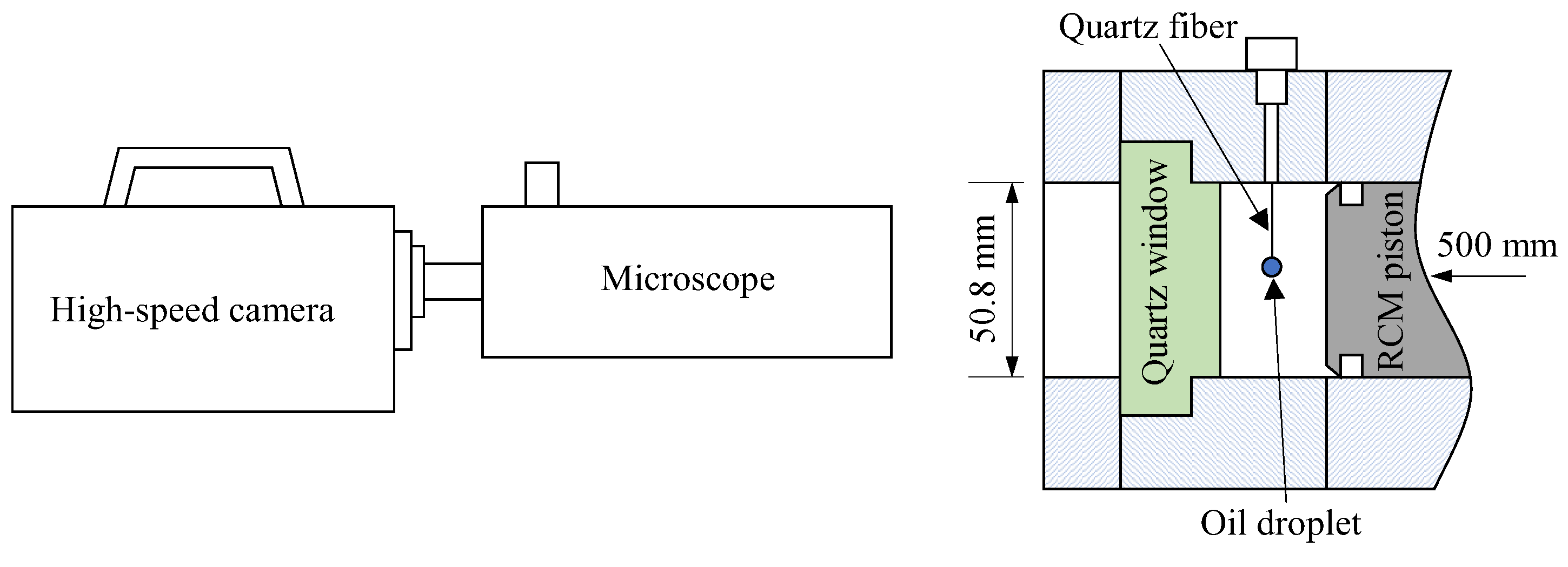
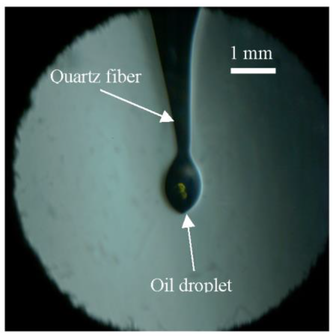
2.1. Experimental Apparatus

The experiments were conducted using a rapid compression machine (RCM), as illustrated in Figure 1. The RCM combustion chamber has a diameter of 50.8 mm and a stroke of 500 mm. By adjusting the clearance of the combustion chamber, different compression ratios (i.e., thermodynamic states at the end of compression, EOC) can be achieved. The end wall of the combustion chamber was fitted with a quartz window (D = 50.80 mm, the same diameter as the combustion chamber) to enable visualization of the entire combustion chamber. To capture the combustion process, a high-speed camera (Fastcam SA-X2, from Photron Ltd., Tokyo, Japan) was used. In cases where close-up observation of oil droplets in the combustion chamber was necessary, a long working distance microscope (QM-1, from Questar Corp., New Hope, PA, USA) was employed to provide high magnification ratios.
Before each experiment, a single droplet was suspended at the tip of a quartz fiber in the center of the combustion chamber, as shown in Figure 1 and Figure 2. The droplet was generated using a micro-syringe with a total measuring range of 1.0 μL and a scale of 0.02 μL. The initial volume of the lubricating oil droplet was 0.1 μL in all experiments. To prevent the oil droplet from falling off, the tip of the quartz fiber was in the shape of a “hook”. Due to the effect of surface tension, the droplet suspended at the quartz fiber tip was too small to form a regular sphere, and hence, an equivalent diameter (Deq) was used to represent the droplet size. The area of the irregularly shaped droplet was determined through image processing, after which Deq was calculated by assuming that there is a circle that has the same area as the oil droplet. As illustrated in Figure 2, the Deq of the oil droplet was approximately 600 μm for an initial volume of 0.1 μL. Once the lubricating oil droplet was suspended, the combustion chamber was vacuumed, and the premixed flammable fuel/air mixture was introduced as the ambient gas for the oil droplet. After allowing about two minutes for the mixture to stabilize, the RCM was activated to compress the mixture. As the compression proceeded, the pressure in the combustion chamber increased. Using the in-chamber dynamic pressure as a trigger signal, the high-speed camera could be triggered at any point during the compression and combustion processes.

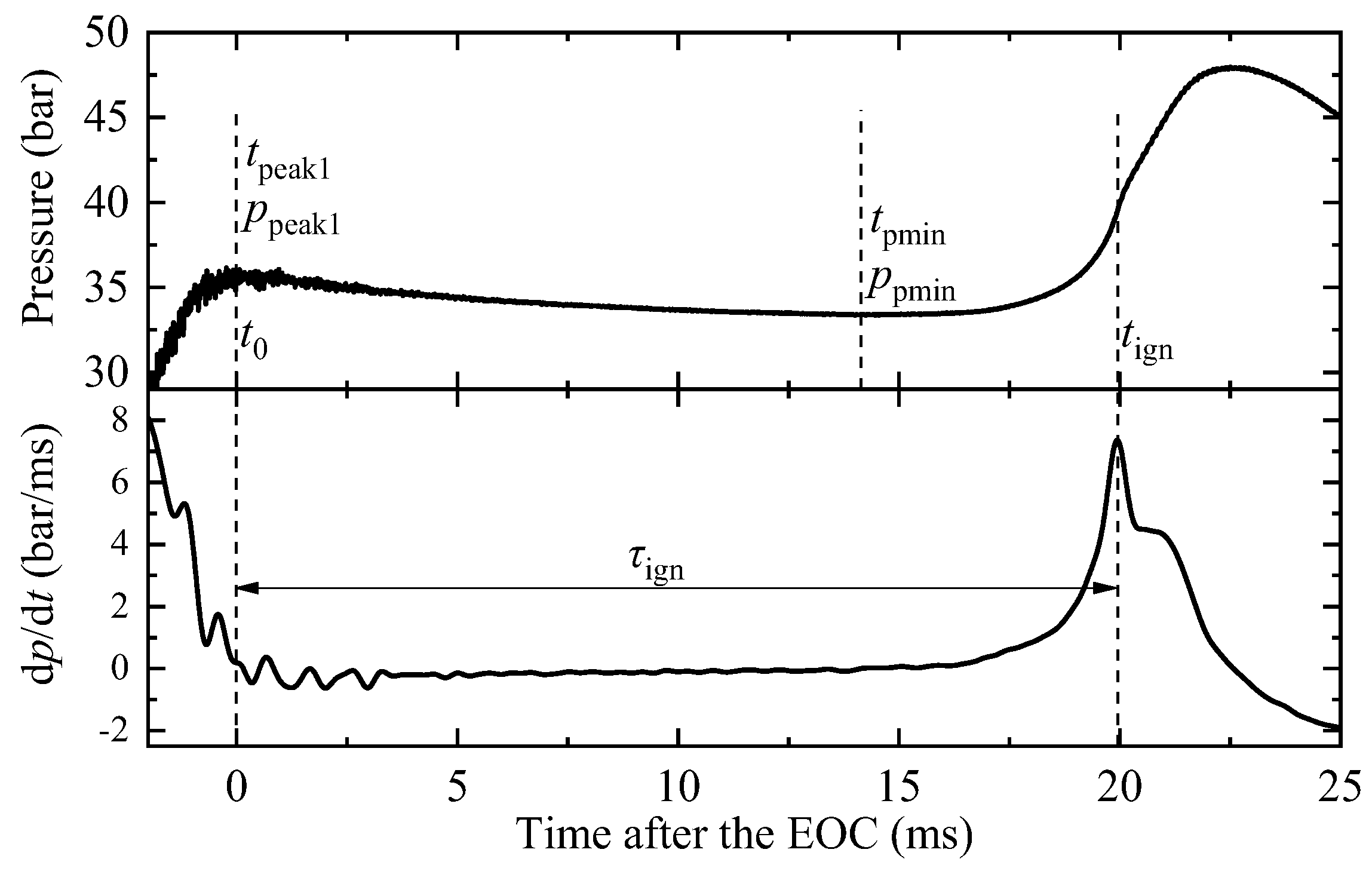
2.2. Data Processing

In this study, the experimental conditions are characterized using effective pressure (peff) and effective temperature (Teff). peff is defined as the integrated average value from the first peak pressure after the end of compression (EOC) to the minimum pressure before ignition [19]. This is calculated using the following equation.
p e f f = 1 ( t p m i n t p e a k 1 ) t p e a k 1 t p m i n p ( t ) d t
where tpeak1 and tpmin represent the time for the first peak pressure and the minimum pressure, respectively. In most cases, tpeak1 coincides with tEOC, as shown in Figure 3.
The effective temperature is then obtained from the effective pressure based on the isentropic assumption in the core reaction zone of rapid compression machines (RCMs). The equation for Teff is given as follows:
T 0 T e f f γ γ 1 d l n T   =   l n ( p e f f p 0 )
where p0 and T0 represent the initial pressure and temperature in the compression chamber, respectively, and γ is the isentropic exponent.
The ignition delay time of the ambient gas (τign in Figure 3) is defined as the interval from the EOC to the time when the pressure rise rate reaches its maximum.

2.3. Properties of Oil and Ambient Gas

The lubricating oil used in this study was a commercially synthesized one for gasoline engines, which was consistent with our previous work [18]. The main components of the oil and their mass fractions are shown in Figure 4. Components with mass fractions below 2% (which account for a total of approximately 6.7%) are not presented. The carbon number ranges from 12 to 54, which is similar to the range mentioned in Ref. [20].
Iso-octane was used as the fuel for the ambient gas, while pure oxygen, nitrogen, and argon were used as the other components of the “air”. Argon was added to increase the effective temperature. Unless otherwise specified, the molar ratio of iso-octane:oxygen:nitrogen:argon was maintained at 1:12.5:47:178 to create the ambient gas, which is stoichiometric but with a higher level of dilution.

3. Results and Discussion

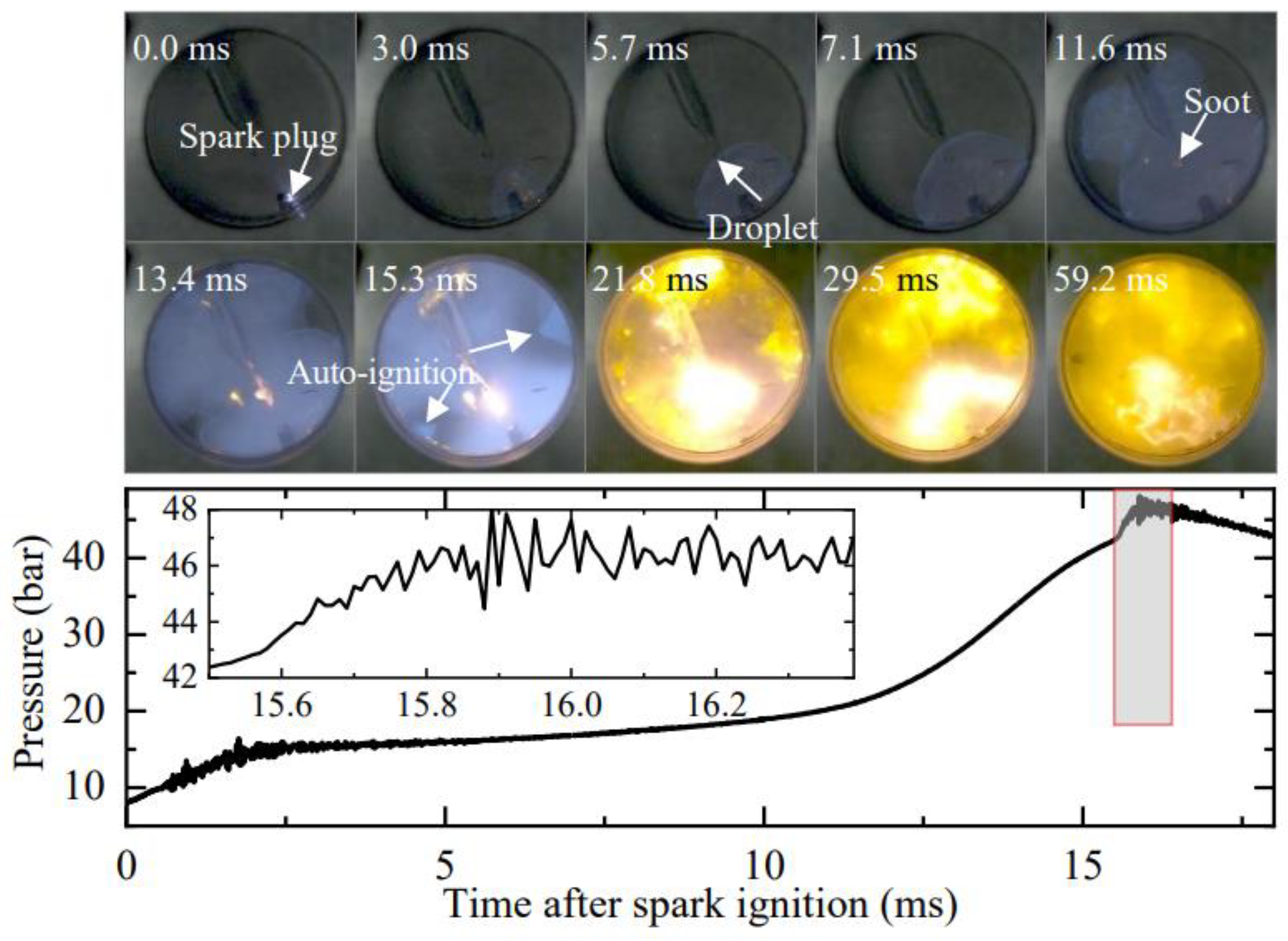
3.1. Ignition and Explosion of Lubricating Oil Droplets

In a previous study, we reported that when an oil droplet is placed in a homogeneous charge compression ignition environment, it could explode if the ignition delay of the ambient gas is relatively short [18]. An example of such an explosion is shown in Figure 5, where a lubricating oil droplet explodes in a compression ignition environment with peff = 32 bar and Teff = 1090 K. The ambient flammable gas ignites homogeneously at 1.72 ms, and by this time, no noticeable change is observed in the oil droplet. At 1.75 ms, the blue flame generated by the homogeneous ignition of the ambient gas has almost completely disappeared. Then, yellow dots start to appear at the position of the oil droplet at 1.79 ms, indicating the generation of soot due to the burning of the oil vapor. As the burning continues, a flame-ball-like soot cloud is formed, expanding outwards from the original position of the oil droplet, similar to an explosion. The pressure trace reveals that the ignition of the ambient gas results in a strong pressure oscillation lasting for more than 1.5 ms, with a maximum pressure and amplitude exceeding 79 bar and 24 bar, respectively.

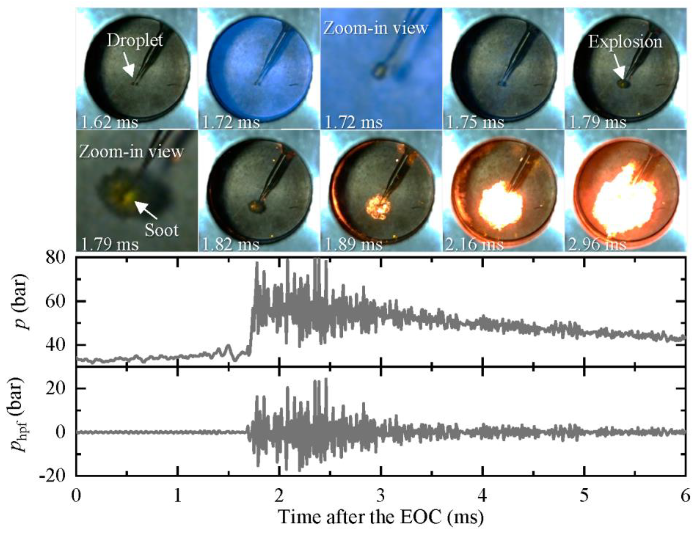
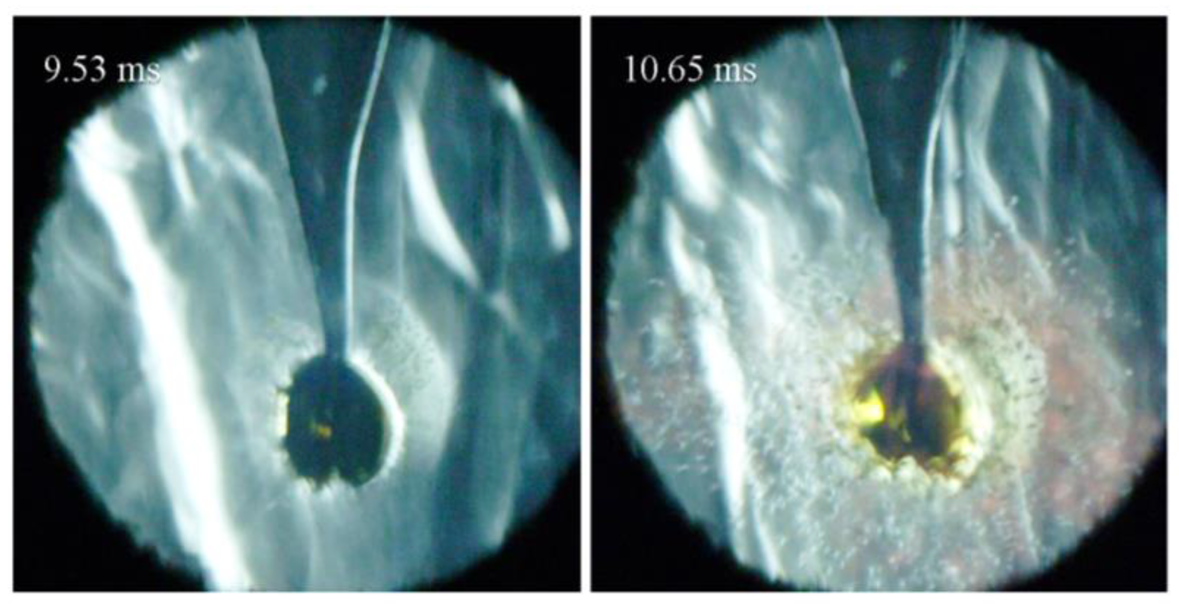
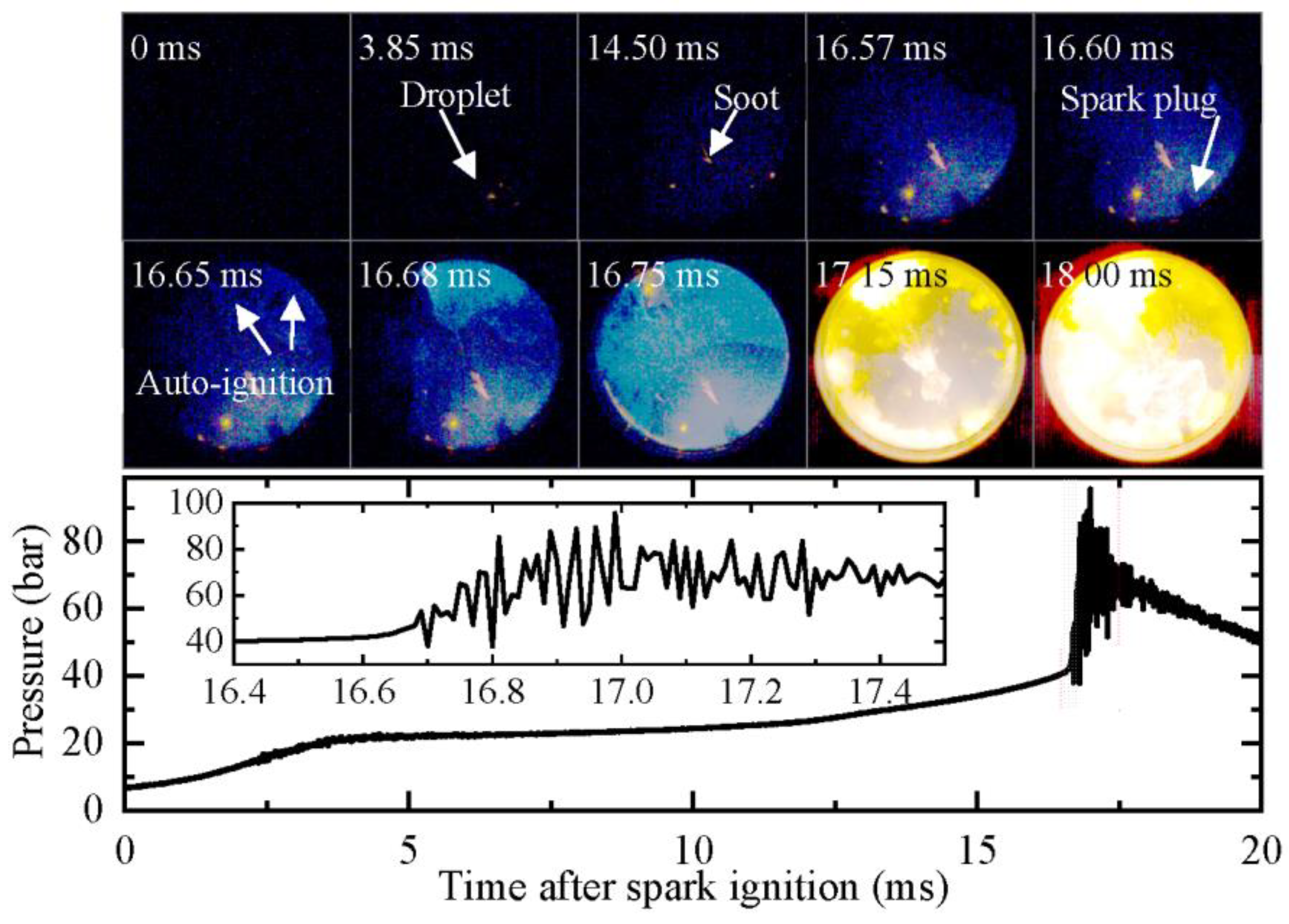
3.2. Microphotography of Oil Droplet Explosion

To examine the detailed process of the oil droplet explosion, we conducted microphotography with a long working distance microscope, as described in our previous study [18]. In Figure 6, we present images of 3 oil droplet explosion processes. In all 3 cases, the initial oil droplet volume was 1.0 μL (Deq = 600 μm), and the Teff of the ambient gas was around 1070 K while the peff increased from 13 bar to 31 bar.
To ensure sufficient light for recording the oil droplet explosion process, we set the frame rate of the camera at 12,500 frames per second. Although the high magnification ratio of the long working distance microscope resulted in a high f-number, the chosen frame rate was not too high to make the exposure duration too short, nor was it too low to capture the detailed process of the droplet explosion. Nonetheless, the recorded images were still dim, and therefore, we processed them to improve their brightness and contrast.
For Case (a) (peff = 13 bar, Teff = 1063 K), the pressure shows a noticeable rise at 8.60 ms after the EOC, indicating that the ambient gas has started to auto-ignite. The pressure reaches its maximum at 10.1 ms with an oscillating amplitude of around 1 bar. During this auto-ignition process, the oil droplet expands sharply and reaches twice its initial size at 9.37 ms. Subsequently, the surface of the droplet becomes significantly wrinkled, and some smaller droplets fly from the droplet into the ambient gas (9.53 to 10.17 ms). The oil droplet then explodes into many tiny droplets, which fill almost the entire field of view (10.65 to 11.61 ms). The tiny droplets rapidly evaporate and ignite, producing a large amount of glowing soot of a reddish color. After the droplet explosion, some oil remains on the fiber tip, but its size is small, and it is heavily deformed (33.77 ms). Figure 7 presents an enlarged version of the image at droplet explosion and deformation, which clearly shows that many tiny droplets and a large amount of glowing soot are generated surrounding the deformed oil droplets.
For Case (b) (peff = 22 bar, Teff = 1074 K), the ambient gas ignites at 4.08 ms. Although the droplet still expands significantly before it explodes, as in the first case, no tiny droplets fly out from the droplet (4.12 ms). On the contrary, a more severe explosion appears at 4.16 ms. Afterwards, the droplet disappears, and a cloud, possibly consisting of oil vapor and fine droplets, appears around the original location of the droplet (4.20 to 4.28 ms). Then, a large amount of glowing soot from the explosion spread across the field of view. Unlike the first case, no oil remains on the quartz fiber in this case after the explosion (4.40 ms).
For Case (c) (peff = 31 bar, Teff = 1078 K), there is no distinct expansion of the droplet until 1.82 ms after the EOC, at which point the ambient gas ignites. With the ignition of the ambient gas, the droplet starts to explode violently almost at the same time, resulting in a dark cloud surrounding the original position of the droplet. Then, massive luminous soot is generated throughout the field of view. After the explosion, there was also no oil remaining on the quartz fiber (2.14 to 2.38 ms).
Upon comparing these three cases, it can be observed that as the effective pressure increases, the time difference between the droplet explosion (texp) and the ignition time of the ambient gas (tig) becomes shorter and follows an exponential pattern, as depicted in Figure 8. Moreover, the severity of the droplet explosion increases while the size of the droplets produced by the explosion decreases. Additionally, it can be noted that at higher effective pressures, the expansion of the oil droplet before the explosion becomes less significant.

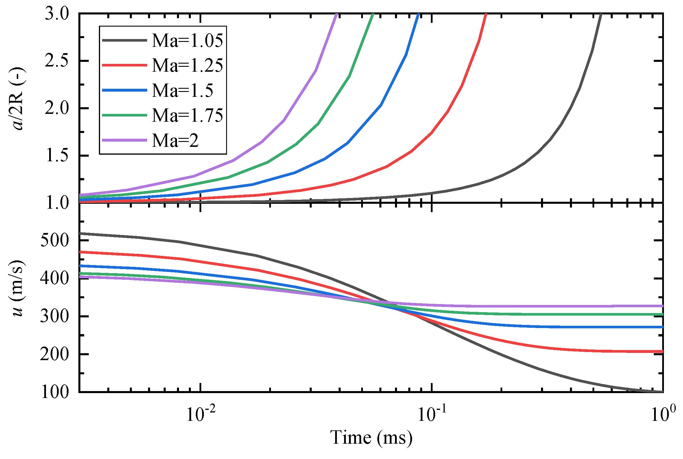
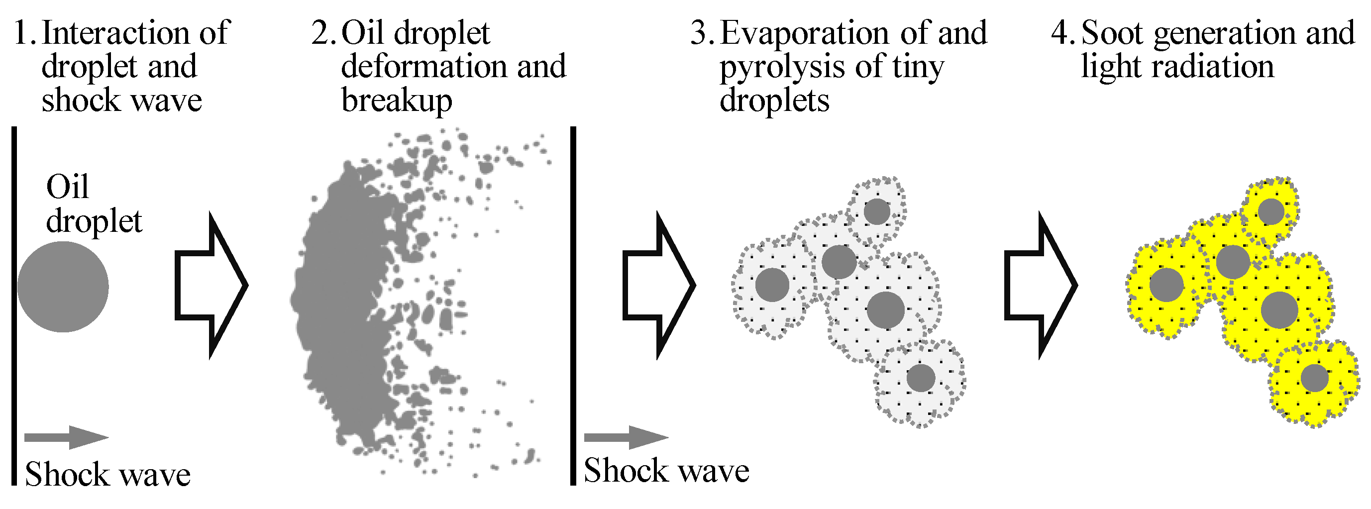
3.3. Mechanism of Oil Droplet Explosion

Section 3.2 has demonstrated that the explosion intensity of the droplets increases with the initial pressure. This phenomenon may be attributed to the intensified pressure oscillation after the auto-ignition of the ambient gas. The pressure oscillation is caused by the propagation of shock waves back and forth in the combustion chamber. When the shock wave impacts on the droplet, it results in deformation, expansion, and breakup of the droplet [21]. Additionally, the auto-ignition of the ambient gas generates high temperatures, which cause the low-saturation temperature components inside the droplet to vaporize and form bubbles. If these bubbles cannot be released from the droplet surface, they will accumulate and merge to form larger bubbles. The expansion of these larger bubbles will ultimately lead to droplet explosions [22,23].
To further investigate the influence of high temperature and shock wave on droplet explosion, additional experiments were conducted. Firstly, a high-temperature environment was generated by compressing pure argon, thereby isolating the effect of high temperature from that of shock waves. Additionally, a flammable ambient gas was employed to explore the effects of high temperatures at even higher temperatures. To avoid generating shock waves, a low initial pressure was used first, and spark ignition was employed. The goal of spark ignition was also to provoke droplet ignition when the propagating flame engulfed the droplet in order to determine if increasing the heat transfer to the interior of the droplet could cause it to explode. Subsequently, under spark ignition conditions, the initial pressure of the ambient gas was further increased to generate shock waves. The experimental conditions are summarized in Table 1.
The development of the oil droplet in a pure argon compression environment (Case 1 in Table 1, peff = 23 bar, Teff = 1659 K) is illustrated in Figure 9. In this case, the oil droplet only undergoes slight deformation due to the vibration of the RCM and does not explode. One possible reason for this is that the high temperature and pressure did not persist for a sufficiently long duration during the experiment. Additionally, the saturation temperatures of the components contained in the droplet were high [17,20]. The heat absorbed by the droplet made it difficult for the components to reach their saturation temperatures, hindering the formation of bubbles inside the droplet.
Figure 10 illustrates the development of the oil droplet under low-pressure spark ignition conditions (Case 2 in Table 1, peff = 10.8 bar, Teff = 701 K). To simulate the no-oxygen environment in gasoline engines, the equivalent ratio of the mixture was set to 1.2, and 20% additional nitrogen was added to suppress end-gas auto-ignition and pressure oscillation. The images depict that the flame front arrives at the oil droplet 4.7 ms after the spark timing, but the droplet does not ignite. Subsequently, the flame front propagates to the unburned mixture, creating a burnt no-oxygen environment for the oil droplet. During this period, the oil droplet does not change significantly. At 11.4 ms, a bright, small yellow region appears at the oil droplet, which is the soot cloud produced from oil pyrolysis in the no-oxygen environment. Afterward, the soot cloud moves with the gas flow but does not significantly expand into the surroundings, indicating that the oil droplet does not explode. This can be attributed to the large size of the oil droplet and the short duration of the high temperature, which does not allow the lighter components to reach their boiling points. Therefore, the high temperature generated by combustion does not significantly affect the oil droplet.
Figure 11 depicts the oil droplet development under medium-pressure spark ignition (Case 3 in Table 1, peff = 15.7 bar, Teff = 703 K). Compared to low-pressure spark ignition (Case 2), the peff is increased from 10.8 bar to 15.7 bar to enhance the possibility of generating stronger shock waves during combustion. At 6.0 ms after spark timing, the flame front engulfs the oil droplet, and no significant change in the oil droplet occurs. At 11.6 ms, soot formation starts on the droplet. However, the expansion of the soot region is not substantial in the subsequent process, and its expansion is primarily along the quartz fiber. At 15.3 ms, end-gas auto-ignition occurs near the combustion chamber wall, and the pressure rapidly rises with slight oscillation. Immediately afterward, a glowing soot cloud forms and continues expanding outward. This phenomenon is highly similar to the oil droplet explosion observed in Figure 5 and Figure 6.
Comparing the experimental results in Figure 10 and Figure 11, it is evident that end-gas auto-ignition is a crucial factor in triggering oil droplet explosions, as shock waves generated by the auto-ignition reflect back and forth in the combustion chamber and impact the droplet, leading to its explosion.
In order to gain further insights into the role of shock waves in oil droplet explosions, an experiment was conducted at a higher pressure. The results are presented in Figure 12, which shows the development of the oil droplet at peff = 22.9 bar (Case 4 in Table 1). To prevent the saturation of captured images by strong auto-ignition-produced high brightness, which would result in the failure to identify the oil droplet explosion, the exposure duration of the high-speed camera was shortened. With the shorter exposure duration, the image brightness of the flame propagation process was reduced. The images from 0 to 16.75 ms in Figure 12 have been enhanced for clarity.
Similar to Case 2, only a small region of soot was produced at the oil droplet after the flame swept over it. As shown in Figure 12, the soot region does not expand significantly from 14.5 to 16.75 ms. At 16.68 ms, end-gas auto-ignition occurs, producing shock waves that oscillate in the combustion chamber. At 17.15 ms, the oil droplet explodes, generating a large amount of glowing soot. The soot cloud expands outward with the gas motion caused by the shock wave oscillation and quickly fills the lower part of the combustion chamber. These results provide strong evidence that shock waves generated by end-gas auto-ignition play a critical role in triggering oil droplet explosions.
In conclusion, the findings presented in Figure 11 and Figure 12 demonstrate that shock waves generated during ambient combustion play a crucial role in triggering oil droplet explosions, and the explosion intensity increases as the intensity of the shock waves increases.
Given that the explosion of droplets in this study is caused by shock waves, the main factor that contributes to changes in droplet size and the expansion of the generated soot cloud is droplet breakup following the impact of the shock wave. The mechanisms of droplet breakup under different Mach and Weber numbers have been thoroughly studied and understood in depth [24]. Regardless of the breakup mechanism, the droplet breakup process typically undergoes two stages after the shock wave impact [25]. In the first stage, the droplet is deformed into an ellipsoid due to forces exerted by the shock wave impact, and in the second stage, a breakup occurs near the droplet surface due to various instabilities [26], resulting in the formation of smaller droplets. Lu et al. [27] employed a simple model to describe the evolution of a droplet from a sphere to an ellipsoid. When the major axis length of the ellipsoid reaches a critical value, it is assumed that the droplet will break up. The model is expressed as follows:
{ | 1 a d a d t = ( μ g ρ g μ l ρ l ) 1 / 3 ρ g u R Δ p | 1 u 2 d u d t = 3 C x 8 a ρ l
where a is the major axis length of the ellipsoid, u is the relative velocity between the droplet and the ambient gas, μ is the dynamic viscosity (in Pa·s), and ρ is the density in (kg/m3). The subscripts g and l denote the gaseous and liquid phases, respectively. R is the initial droplet radius, and Δp is the pressure difference between the two sides of the shock wave. t is the time. Cx is a constant, taken as 1.6 to 3.0 [28].
For the cases examined in this paper, the droplet is still formed prior to the generation of the shock wave. As a result, the initial relative velocity between the droplet and the ambient gas, denoted as u0, can be considered the gas velocity downstream of the shock wave. Moreover, the pressure difference Δp experienced by the droplet can be considered as the sum of the aerodynamic pressure and the Laplace pressure [27]. In this study, the droplet size is on the order of hundreds of micrometers, and the Laplace pressure (ranging from hundreds to thousands of pascals) is much smaller than the aerodynamic pressure (ranging from tens to hundreds of thousands of pascals). Therefore, the Laplace pressure can be neglected, and Δp can be approximated as the aerodynamic pressure difference between the two sides of the shock wave. The following equations can be used to calculate u0 and Δp based on aerodynamic principles [29].
{ u 0 = 2   +   ( γ     1 ) M a 2 ( γ   +   1 ) M a c Δ p = 2 γ ( M a 2 1 ) ( γ   +   1 ) p 0
where Ma is the Mach number of the shock wave, c is the sound speed of the ambient gas, and p0 is the pressure before the shock wave is generated.
In this study, the variation of a and u with time for different Mach numbers is presented in Figure 13, assuming R = 300 μm, p0 = 40 bar, γ = 1.4, and c = 550 m/s. The major axis length is normalized in the form of a/2R. It is observed that the major axis length can increase to more than twice the initial diameter in less than 1 ms, even with a Mach number as low as 1.05. The increase in major axis length is significantly advanced as the Mach number increases, indicating that high Mach numbers accelerate the deformation of the droplet. This suggests that the droplet will explode more violently at higher Mach numbers, i.e., higher Δp, which is consistent with the experimental results presented in Figure 6, Figure 11 and Figure 12. As shown in Figure 13, the initial relative velocity decreases with increasing Mach numbers. This is because the initial relative velocity is the velocity post-shock wave, and according to Equation (4), the gas velocity post-shock wave decreases as Mach number increases. However, the decreasing trend of the relative velocity decreases with increasing Mach numbers. This is because, according to Equation (3), the relative velocity is inversely proportional to a. The increase in a is fast at high Mach numbers, so the change in relative velocity is relatively small.
Based on both experimental and numerical results, it can be concluded that the shock wave is the key factor in inducing the explosion of oil droplets in a combustion environment, rather than high temperature alone. The process of an oil droplet explosion can be summarized as follows: Under certain conditions, combustion generates shock waves. When a shock wave impacts an oil droplet, the droplet deforms, grows in size, and eventually breaks up into numerous tiny droplets, forming an oil mist. The tiny droplets in the mist then evaporate in the high-temperature, high-pressure burned gas. However, due to a lack of oxygen, the evaporated oil undergoes pyrolysis, generating soot. The high-temperature soot emits light through black-body radiation, creating a fireball-like soot cloud. As the shock wave in the combustion chamber oscillates, the soot cloud moves with the gas flow induced by the shock wave, expanding in size. Additionally, during this process, the oil droplets in the soot cloud may be impacted multiple times by the oscillating shock waves, further promoting the expansion of the soot cloud. Consequently, an initially small oil droplet rapidly grows into an expanding soot cloud that appears to be an explosion. A schematic depiction of this process is provided in Figure 14.

4. Conclusions

Through the suspension of a single lubricating oil droplet with a volume of 0.1 μL (~600 μm in diameter) in a rapid compression machine, the explosion of oil droplets at high temperatures was visualized using high-speed photography and micrography. The effects of temperature and shock waves on oil droplet explosion were experimentally studied, and the droplet deformation after shock wave impact was also calculated using a simple model. Based on the results, the following conclusions can be drawn:
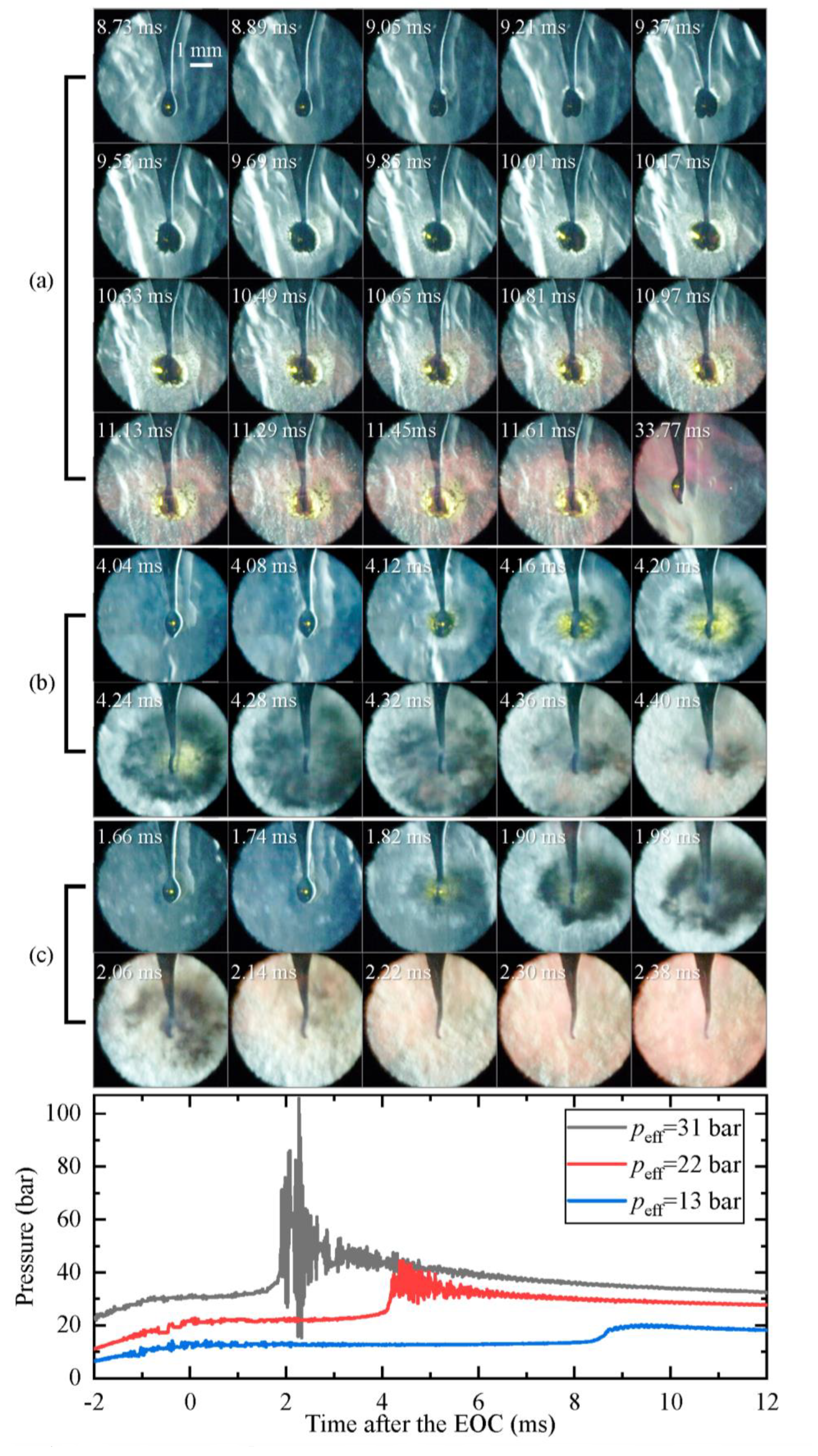
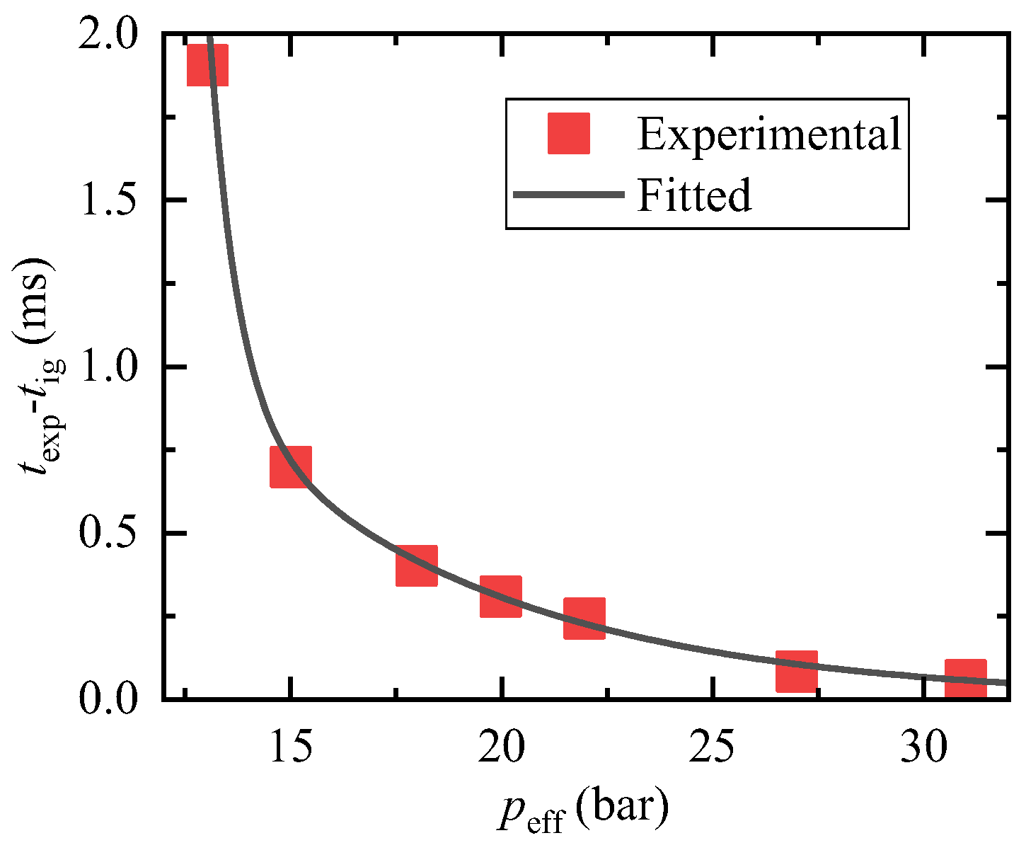
  • Lubricating oil droplets can explode and develop into a soot cloud in HCCI-like combustion environments with a short ignition delay time. As the pressure of the ambient flammable gas increases, the oil droplet explodes more severely and earlier;
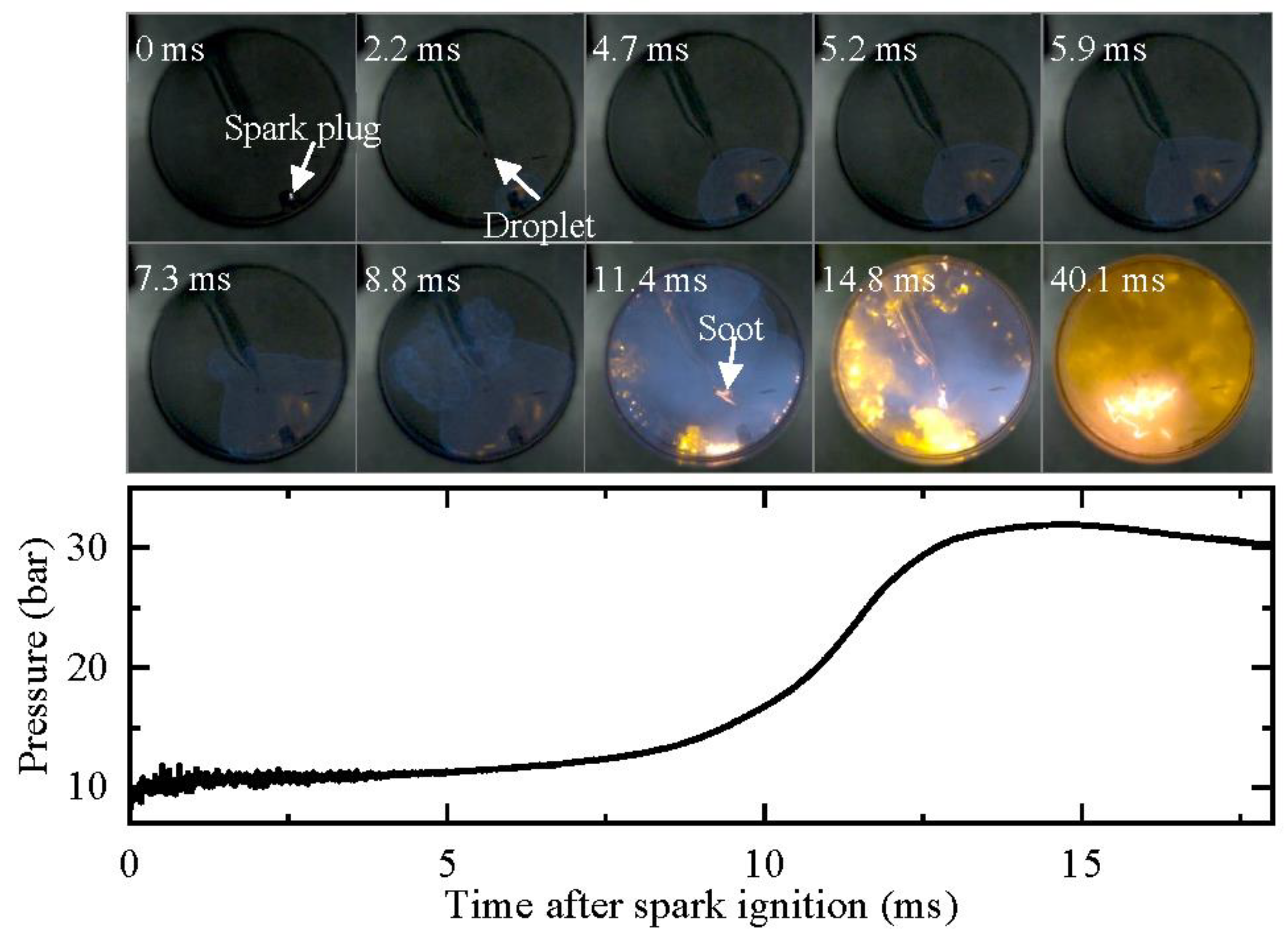
  • The key factor in inducing oil droplet explosions is the shock waves generated by the combustion of the ambient gas. In cases of high temperature alone, without shock waves, the oil droplet cannot explode during the entire combustion process, even if surrounded by a flame;
  • The mechanism of oil droplet explosion is as follows: the impact of shock waves on the droplet deforms and breaks up the oil droplet into many tiny droplets. The evaporation and pyrolysis of these tiny droplets in a high-temperature and high-pressure environment lacking oxygen generate a glowing soot cloud. The expansion of the soot cloud with oscillating shock waves and gas flow in the combustion chamber creates an explosion-like appearance.

Author Contributions

Conceptualization, Y.Q. and Z.W.; methodology, Y.Q. and S.F.; software, Y.Q. and S.F.; validation, Y.Q., S.F. and Z.W.; formal analysis, Y.Q. and S.F.; investigation, Y.Q. and S.F.; resources, Z.W.; data curation, Y.Q. and Z.W.; writing—original draft preparation, Y.Q. and S.F.; writing—review and editing, Y.Q. and Z.W.; visualization, Y.Q. and S.F.; supervision, Z.W.; project administration, Z.W.; funding acquisition, Z.W. All authors have read and agreed to the published version of the manuscript.

Funding

This research was funded by the National Natural Science Foundation of China, grant number T2241003, 52076118.

Data Availability Statement

Not applicable.

Conflicts of Interest

The authors declare no conflict of interest.

References

  1. Wang, Z.; Liu, H.; Reitz, R.D. Knocking combustion in spark-ignition engines. Prog. Energy Combust. Sci. 2017, 61, 78–112. [Google Scholar] [CrossRef]
  2. Rönn, K.; Swarts, A.; Kalaskar, V.; Alger, T.; Tripathi, R.; Keskiväli, J.; Kaario, O.; Santasalo-Aarnio, A.; Reitz, R.; Larmi, M. Low-speed pre-ignition and super-knock in boosted spark-ignition engines: A review. Prog. Energy Combust. Sci. 2023, 95, 101064. [Google Scholar] [CrossRef]
  3. Gong, Z.; Hu, M.; Fang, Y.; Zhang, D.; Feng, L. Mechanism study of natural gas pre-ignition induced by the auto-ignition of lubricating oil. Fuel 2022, 315, 123286. [Google Scholar] [CrossRef]
  4. Dahnz, C.; Han, K.-M.; Spicher, U.; Magar, M.; Schiessl, R.; Maas, U. Investigations on Pre-Ignition in Highly Supercharged SI Engines. SAE Int. J. Engines 2010, 3, 214–224. [Google Scholar] [CrossRef]
  5. Fujimoto, K.; Yamashita, M.; Hirano, S.; Kato, K.; Watanabe, I.; Ito, K. Engine Oil Development for Preventing Pre-Ignition in Turbocharged Gasoline Engine. SAE Int. J. Fuels Lubr. 2014, 7, 869–874. [Google Scholar] [CrossRef]
  6. Mayer, M.; Hofmann, P.; Geringer, B.; Williams, J.; Moss, J. Influence of Different Fuel Properties and Gasoline–Ethanol Blends on Low-Speed Pre-Ignition in Turbocharged Direct Injection Spark Ignition Engines. SAE Int. J. Engines 2016, 9, 841–848. [Google Scholar] [CrossRef]
  7. Kassai, M.; Torii, K.; Shiraishi, T.; Noda, T.; Goh, T.K.; Wilbrand, K.; Wakefield, S.; Healy, A.; Doyle, D.; Cracknell, R.; et al. Research on the Effect of Lubricant Oil and Fuel Properties on LSPI Occurrence in Boosted S. I. Engines; SAE Technical Paper: Warrendale, PA, USA, 2016; p. 2016-01-2292. [Google Scholar] [CrossRef]
  8. Han, K.; Pang, B.; Ma, X.; Chen, H.; Song, G.; Ni, Z. An experimental study of the burning characteristics of acetone–butanol–ethanol and diesel blend droplets. Energy 2017, 139, 853–861. [Google Scholar] [CrossRef]
  9. Wu, M.S.; Yang, S.I. Combustion characteristics of multi-component cedar bio-oil/kerosene droplet. Energy 2016, 113, 788–795. [Google Scholar] [CrossRef]
  10. Ambekar, A.; Maurya, A.K.; Chowdhury, A. Droplet combustion studies of nitromethane and its blends. Exp. Therm. Fluid Sci. 2018, 93, 431–440. [Google Scholar] [CrossRef]
  11. Glushkov, D.O.; Strizhak, P.A. Ignition of composite liquid fuel droplets based on coal and oil processing waste by heated air flow. J. Clean. Prod. 2017, 165, 1445–1461. [Google Scholar] [CrossRef]
  12. Kim, H.; Baek, S.W. Combustion of a single emulsion fuel droplet in a rapid compression machine. Energy 2016, 106, 422–430. [Google Scholar] [CrossRef]
  13. Ohtomo, M.; Miyagawa, H.; Koike, M.; Yokoo, N.; Nakata, K. Pre-Ignition of Gasoline-Air Mixture Triggered by a Lubricant Oil Droplet. SAE Int. J. Fuels Lubr. 2014, 7, 673–682. [Google Scholar] [CrossRef]
  14. Ohtomo, M.; Suzuoki, T.; Miyagawa, H.; Koike, M.; Yokoo, N.; Nakata, K. Fundamental analysis on auto-ignition condition of a lubricant oil droplet for understanding a mechanism of low-speed pre-ignition in highly charged spark-ignition engines. Int. J. Engine Res. 2018, 20, 292–303. [Google Scholar] [CrossRef]
  15. Wang, Z.; Zhang, D.; Fang, Y.; Song, M.; Gong, Z.; Feng, L. Experimental and numerical investigation of the auto-ignition characteristics of cylinder oil droplets under low-speed two-stroke natural gas engines in-cylinder conditions. Fuel 2022, 329, 125498. [Google Scholar] [CrossRef]
  16. Niegemann, P.; Herzler, J.; Fikri, M.; Schulz, C. Studying the influence of single droplets on fuel/air ignition in a high-pressure shock tube. Rev. Sci. Instrum. 2020, 91, 105107. [Google Scholar] [CrossRef] [PubMed]
  17. Yi, P.; Long, W.; Feng, L.; Wang, W.; Liu, C. An experimental and numerical study of the evaporation and pyrolysis characteristics of lubricating oil droplets in the natural gas engine conditions. Int. J. Heat Mass Transf. 2016, 103, 646–660. [Google Scholar] [CrossRef]
  18. Fei, S.; Wang, Z.; Qi, Y.; Wang, Y.; Zhang, H. Ignition of a Single Lubricating Oil Droplet in Combustible Ambient Gaseous Mixture under High-Temperature and High-Pressure Conditions. Combust. Sci. Technol. 2019, 191, 2033–2052. [Google Scholar] [CrossRef]
  19. He, X.; Donovan, M.T.; Zigler, B.T.; Palmer, T.R.; Walton, S.M.; Wooldridge, M.S.; Atreya, A. An experimental and modeling study of iso-octane ignition delay times under homogeneous charge compression ignition conditions. Combust. Flame 2005, 142, 266–275. [Google Scholar] [CrossRef]
  20. Kuti, O.A.; Yang, S.Y.; Hourani, N.; Naser, N.; Roberts, W.L.; Chung, S.H.; Sarathy, S.M. A fundamental investigation into the relationship between lubricant composition and fuel ignition quality. Fuel 2015, 160, 605–613. [Google Scholar] [CrossRef]
  21. Poplavski, S.V.; Minakov, A.V.; Shebeleva, A.A.; Boyko, V.M. On the interaction of water droplet with a shock wave: Experiment and numerical simulation. Int. J. Multiph. Flow 2020, 127, 103273. [Google Scholar] [CrossRef]
  22. Antonov, D.V.; Fedorenko, R.M.; Strizhak, P.A. Micro-Explosion Phenomenon: Conditions and Benefits. Energies 2022, 15, 7670. [Google Scholar] [CrossRef]
  23. Zhang, X.; Li, T.; Wang, B.; Wei, Y. Superheat limit and micro-explosion in droplets of hydrous ethanol-diesel emulsions at atmospheric pressure and diesel-like conditions. Energy 2018, 154, 535–543. [Google Scholar] [CrossRef]
  24. Sharma, S.; Chandra, N.K.; Basu, S.; Kumar, A. Advances in droplet aerobreakup. Eur. Phys. J. Spec. Top. 2022, 2022, 1–15. [Google Scholar] [CrossRef]
  25. Nicholls, J.A.; Ranger, A.A. Aerodynamic shattering of liquid drops. AIAA J. 1969, 7, 285–290. [Google Scholar] [CrossRef]
  26. Sharma, S.; Pratap Singh, A.; Srinivas Rao, S.; Kumar, A.; Basu, S. Shock induced aerobreakup of a droplet. J. Fluid Mech. 2021, 929, A27. [Google Scholar] [CrossRef]
  27. Lu, S.; Qin, Y. Deformation and breakup of droplets behind shock wave. Chin. J. High Press. Phys. 2000, 14, 151–154. [Google Scholar]
  28. Frolov, S.M. Modeling of Droplet Dformation and Breakup Conditions. In Proceedings of the 16th International Colloquium on the Dynamics of Explosions and Reactive Systems, Cracow, Poland, 3–8 August 1997; pp. 417–420.sa. [Google Scholar]
  29. Anderson, J. Fundamentals of Aerodynamics, 6th ed.; McGraw-Hill Education: New York, NY, USA, 2017. [Google Scholar]
Figure 1. Schematic of the experimental setup.
Lubricants 11 00118 g001
Figure 2. A lubricating oil droplet suspended at the tip of a quartz fiber.
Lubricants 11 00118 g002
Figure 3. Definition of the parameters used to calculate peff and Teff.
Lubricants 11 00118 g003
Figure 4. Main components of the lubricating oil used in this study.
Lubricants 11 00118 g004
Figure 5. An example of a lubricating oil droplet explosion (peff = 32 bar, Teff = 1090 K, ID = 1.72 ms, Deq = 600 μm). Images were taken at 10,000 fps with an exposure duration of 100 μs.
Lubricants 11 00118 g005
Figure 6. Droplet explosion processes under different initial conditions. Images were taken at 12,500 fps with an exposure duration of 80 μs. (a) p0 = 0.30 bar, peff = 13 bar, Teff = 1063 K, ID = 8.60 ms; (b) p0 = 0.50 bar, peff = 22 bar, Teff = 1074 K, ID = 4.20 ms; (c) p0 = 0.70 bar, peff = 31 bar, Teff = 1078 K, ID = 1.85 ms.
Lubricants 11 00118 g006
Figure 7. Close-up view of droplet explosion for two images of Case (a) in Figure 6.
Lubricants 11 00118 g007
Figure 8. Time difference between droplet explosion and ignition of the ambient gas.
Lubricants 11 00118 g008
Figure 9. Development of oil droplet in a pure argon compression environment (peff = 23 bar, Teff = 1659 K). Images were taken at 10,000 fps with exposure duration of 100 μs.
Lubricants 11 00118 g009
Figure 10. Development of oil droplet under low-pressure spark ignition (peff = 10.8 bar, Teff = 701 K). Images were taken at 10,000 fps with exposure duration of 100 μs.
Lubricants 11 00118 g010
Figure 11. Development of oil droplet under medium-pressure spark ignition (peff = 15.7 bar, Teff = 703 K). Images were taken at 10,000 fps with exposure duration of 100 μs.
Lubricants 11 00118 g011
Figure 12. Development of oil droplet under high-pressure spark ignition (peff = 22.9 bar, Teff = 709 K). Images were taken at 10,000 fps with exposure duration of 1 μs.
Lubricants 11 00118 g012
Figure 13. Variation of droplet major axis length and relative velocity between the droplet and gas flow with time under different Δp.
Lubricants 11 00118 g013
Figure 14. Sketch of the process of lubricating oil droplet explosion.
Lubricants 11 00118 g014
Table 1. Experimental conditions for studying the droplet explosion mechanism.
CaseFactorMethodpeff/barTeff/KDroplet Vol./μL
1High temperature Pure Ar compression23.016591.0
2High temperatureLow-pressure SI10.87011.0
3Pressure wave Medium-pressure SI15.77031.0
4Pressure wave High-pressure SI22.97091.0
Disclaimer/Publisher’s Note: The statements, opinions and data contained in all publications are solely those of the individual author(s) and contributor(s) and not of MDPI and/or the editor(s). MDPI and/or the editor(s) disclaim responsibility for any injury to people or property resulting from any ideas, methods, instructions or products referred to in the content.

