Article

Stability and Tribological Performance of Nanostructured 2D Turbostratic Graphite and Functionalised Graphene as Low-Viscosity Oil Additives

by
Gustavo Alves Lau
1,
Guilherme Oliveira Neves
2,
Diego Berti Salvaro
1,
Cristiano Binder
1,
Aloisio Nelmo Klein
1 and
José Daniel Biasoli de Mello
1,3,*
1
Department of Mechanical Engineering, Universidade Federal de Santa Catarina, Florianópolis 88040-900, Brazil
2
Departamento de Ingeniería Mecánica, Faculdad de Ingeniería, Universidad del Bío-Bío, Avenida Collao 1202, Concepción 4081112, Chile
3
Faculdade de Engenharia Mecânica, Universidade Federal de Uberlândia, Uberlândia 38400-902, Brazil
*
Author to whom correspondence should be addressed.
Lubricants 2023, 11(4), 155; https://doi.org/10.3390/lubricants11040155
Submission received: 20 January 2023 / Revised: 6 March 2023 / Accepted: 17 March 2023 / Published: 24 March 2023
(This article belongs to the Special Issue Nanoscale Mechanics and Tribology of 2D Materials and Thin Films)

Abstract

:
The dispersion stability of carbon-based solid lubricants/lubricating oils remains a challenge to overcome. Recently, novel processing routes were developed to obtain 2D turbostratic graphite particles via solid-state reactions between B4C and Cr3C2 (GBC) and between SiC and Fe (GSF) that present outstanding tribological properties in a dry scenario, as well as functionalized graphene (GNH). This work investigated the suspension stability of GBC and GSF particles (0.05 wt.%) dispersed in a low-viscosity polyol ester lubricating oil and their tribological performance. Ammonia-functionalized graphene (GNH) particles were also used as a reference. In order to evaluate the dispersion stability, in addition to the classical digital image technique, a much more assertive, reliable, quantitative and rarely reported in the literature technique was used, i.e., the STEPTM (Space and Time-resolved Extinction Profiles) technology. Reciprocating sphere-on-flat tribological tests were carried out, in which before contact, 0.2 μL of pure oil and suspension (POE + 0.05 wt.% of solid lubricant) was applied on a flat surface. The results showed that the GBC particles remained remarkably stable and reduced the sphere wear rate by 61.8%. From the tribosystem point of view, the presence of GBC and GSF reduced the wear rate by 18.4% and 2.2%, respectively, with respect to the pure oil, while the GNH particles increased the wear rate by 4.2%. Furthermore, the wear rate was improved due to the highly disordered carbon tribolayer formation identified on both surfaces.

1. Introduction

The worldwide growing energy demand has created an alert for reducing energy consumption [1]. Thus, the decrease in this consumption has been one of the topics of greatest concern in technological development due to its relevance from an economic and environmental point of view. Therefore, acting towards the search for technical solutions to increase mechanical systems’ energy efficiency and useful life is crucial to mitigate the economic, energetic and environmental impacts generated by their production and use [2,3]. One way to contribute to reducing energy consumption related to mechanical components is to reduce or eliminate the friction and wear caused by the relative motion between the parts of a tribosystem [4].
The most convenient solution to this is the application of fluid lubricants, allowing the elimination or reduction of contact between surfaces with relative movement [4]. However, the increasing downsizing associated with higher operating speeds of mechanical systems leads to more severe operating conditions, increasing friction and wear [5]. Furthermore, due to the system’s characteristics, some tribological pairs work under limited or mixed lubrication regimes, which hinders the formation of an oil film separating the surfaces [6]. For this reason, most lubricating fluids contain friction-modifying (FM) and anti-wear additives (AW) [7]. Nonetheless, in 2006, a new regulation was established in Europe restricting and/or eliminating the use of some chemical substances posing risks to human health and the environment. Among these substances are some widely used as FM and AW lubricant additives, especially those containing phosphorus and sulphur [8,9,10,11].
A promising solution is using solid lubricant particles as additives in lubricating oils [11,12,13]. Carbon-based ones, such as fullerenes, nanotubes, graphene, graphite nanosheets and carbide-derived carbon (CDC), have drawn attention due to their allotropy, which allows a wide range of tribological behaviors depending on their crystalline structure and the sp2/sp3 hybridization ratio [14,15,16,17]. Furthermore, the layered structure is one of the typical structures of carbon-based solid lubricants, which generally have much stronger intralayer bonds than interlayer bonds. These features induce low shear resistance and allow the solid lubricant particles to access the tribological interface [12,17,18]. In addition, carbon-based solid lubricant particles can have a minimal size and, consequently, a highly specific surface area. Thus, applying these materials as lubrication oil additives can prevent the direct contact between sliding surfaces, forming a tribofilm that can reduce the friction and wear of tribosystems under limited or mixed lubrication regimes [12,19,20].
Carbon allotropes, such as graphene and graphite, can be obtained by synthesizing carbide-derived carbons (CDC). The CDC synthesis method promotes the formation of carbon structures from the reaction of different carbides. These structures may consist of amorphous carbons, crystalline graphite and carbon sheets (i.e., graphenes) depending on the synthesis conditions [21]. Recently, Neves et al. [22,23] developed a processing route to obtain nanostructured 2D turbostratic graphite particles via solid-state reactions between boron carbide (B4C) and chromium carbide (Cr3C2). These graphite particles have a high disorder degree in the graphene stacking and many point and line structural crystalline defects. As a solid lubricant impregnated in a porous sintered matrix, this material promoted low friction coefficients (~0.1) and high wear resistance (1.8 × 10⁻⁶ mm3·N−1·m−1) concerning commercial 3D graphite particles [22]. The fact that this material has a significant crystalline disorder (turbostraticity) places it as a potential additive for lubricating oils due to its greater propensity to easily shear due to weak interatomic interactions between layers [24,25].
Using carbon-based particles as an additive of lubricating oil to reduce friction and wear has been widely studied [12,26,27,28,29,30]. However, one of the main challenges is maintaining the suspension’s stability. The solid lubricant particles tend to agglomerate when dispersed in fluids due to their high surface tension and cohesive intermolecular interactions. This leads to decantation and reduces the ability of the particles to access the contact interface [30,31,32,33].
Considering all the positive characteristics of the previously presented carbon-based materials, in addition to their environmentally friendly character [31], the use of these materials as a lubrication additive is a promising alternative to additives restricted/banned by regulations. Thus, evaluating suspensions in oil and the tribological properties of newly developed carbon-based materials (CDCs) and comparing them with commercial materials that are already being studied is of interest. For example, this replacement is an alternative for the refrigeration compressor industry, which applies oil-based lubrication to their systems. Since this market has about 3 billion working equipment around the world, and since between 30–40% of home energy consumption in China [32], 30% in Brazil [33] and 7.3% in the USA [34] is attributed to this equipment, this study has a considerable potential for wide application. Therefore, considering this whole scenario, this work studied two distinct types of 2D turbostratic graphite particles obtained by a novel CDC synthesis route (solid-state reactions between B4C and Cr3C2 (GBC) and dissociation of silicon carbide (SiC) in an iron (Fe) matrix (GSF)) and commercial NH3-functionalized graphene (GNH) particles as additives in a low-viscosity polyol ester lubricating oil (POE), a lubricant widely used in the hermetic compressor industry for refrigeration. Firstly, the stability of the suspensions was assessed. Then, their tribological performance was evaluated to elucidate these three particles’ potential as an oil additive.

2. Materials and Methods

The nanostructured 2D turbostratic graphite particles derived from B4C and Cr3C2 (GBC) were synthesized from the reaction between particles of boron carbide (B4C, particle size D50 = 1.5 μm, H.C. Starck, Goslar, Germany) and chromium carbide (Cr3C2, particle size D50 = 1.6 μm, H.C. Starck, Goslar, Germany). The powders were mixed in the proportion of 23.5 wt.% of B4C and 76.5 wt.% of Cr3C2 for 45 min at 30 rpm in a Y-type mixer and reacted at 1400 °C for 1 h in a tubular furnace containing a protective atmosphere (95% Ar and 5% H2). After reacting, the byproducts were removed by dissolving them with a hydrochloric acid solution. Later, the remaining salts were removed by heating the particles to 1000 °C for 1 h in the tubular furnace with the same protective atmosphere. This process is described in detail in previous work [35]. The resulting material consisted of 2D turbostratic graphite particles with irregular geometry and a porous nanostructure, as shown in Figure 1a. The mean particle size was approximately 1.2 μm [22].
We produced 2D turbostratic particles derived from SiC and Fe (GSF) by mixing 18.5 wt.% of hexagonal silicon carbide (SiC, D50 = 10 µm, Micro Service-Micrograf 99,501 UJ, Nacional de Grafite, Brazil) and 81.5 wt.% of pure iron powder (Fe, D50 = 45 µm, AHC100.29, Höganäs do Brazil Ltd., Brazil) in a Y-type mixer for 45 min at 30 rpm. After mixing, alloy powder cylinders were pressed (600 MPa pressure) in a double-action hydraulic press. Then, the samples were sintered in a resistive tubular furnace using a protective atmosphere (95% Ar and 5% H2). The heating rate was 10 °C/min up to the reaction temperature (1150 °C), with a holding time of 60 min. The products of the dissociation, 2D turbostratic graphite particles and Fe–Si matrix, were separated by hydrofluoric acid (HF) chemical extraction, which dissolved the Fe–Si matrix. The resulting material was then filtered and dried [36]. The particle morphology resembled a highly disordered cluster of nanosheets (Figure 1b).
Commercial ammonia plasma-functionalized multilayer graphene particles (Graphene Supermarket Inc) (GNH) with 3.97 wt.% of nitrogen were used as a reference. GNH presents a nanosheet morphology (Figure 1c) with a planar dimension ranging between 400 nm and 3 μm, around 10 nm thick.
Raman spectroscopy (RS) analyses were performed to obtain information about the crystalline structure of the carbon-based solid lubricants. A micro-Raman confocal spectrometer with an Argon laser radiation (λ = 514.5 nm) (Renishaw 2000, Renishaw Instruments, UK) was used to perform the analyses.
The base lubricating oil was a synthetic low-viscosity polyol ester (POE, density: 0.931 g/cm3 at 20 °C, kinematic viscosity at 40 °C: 5.91 cSt, kinematic viscosity at 100 °C: 1.93 cSt, Lubrizol Corporation, Wickliffe, Ohio, United States), without additives. Dispersions of carbon-based solid lubricants in POE oil were prepared as follows (Figure 2): (a) 0.05 wt.% of particles (GBC, GSF or GNH) were added to 25 mL of previously dehumidified POE oil; (b) 90 s of ultrasonication was applied (Misonix S-4000-010) (3 sonications of 30 s with 1 min of rest between each sonication, to prevent overheating); (c) 0.2 µL of each suspension was collected, immediately after ultrasonication, with the aid of a pipette and promptly applied on the specimen for the tribological test; (d) 5 mL of each suspension was immediately poured into a transparent vial for visual suspension stability analysis. Another 2 mL was immediately poured in the polycarbonate transparent cells for an accelerated analysis of suspension stability. The suspension ultrasonication and application procedure were replicated just before every tribological test.
The suspensions’ stability was analyzed via digital images. Photos were taken immediately after sonication for 30 days (daily pictures). Vials containing the suspensions were kept still and untouched in a room with controlled temperature (20 ± 2 °C) and moisture (45 ± 5%).
In addition, the accelerated analysis of suspension stability was performed using an accelerated multisample analytical photo-centrifuge (LUMiSizer®-6110-87 model). This multisample analytical centrifuge displays multi-wavelength light (Near Infra-Red and Blue Light Sources) transmitted across the entire length of up to 12 polycarbonate transparent cells containing the samples. A transmission profile of each sample was recorded by a CCD (charged-coupled device) line sensor. The LUMISizer® employs the STEPTM (Space and Time-resolved Extinction Profiles) technology. Particle migration due to centrifugal force results in the variation of the local particle concentration, and correspondingly, local and temporal transmission variations occur. This technique allows the simultaneous measurement of light transmitted intensity as a time and position function over the entire sample length, enabling the instantaneous display of in situ changes of particle concentration and sedimentation. Therefore, both “constant position” and “constant time” were measured. The data are displayed as a function of the distance from the center of rotation (radial position). The progression of the transmission profiles provides information on the kinetics of the separation process [37]. Two milliliters of each sample obtained after sonication of POE + 0.05 wt.% of GBC, GSF and GNH was analyzed simultaneously (25 ± 1 °C, 4000 rpm, 255 profiles, interval between profiles of 60 s, test time of 4.25 h).
The tribological performance of the POE oil and solid lubricant suspensions (GBC, GSF and GNH) was evaluated in terms of coefficient of friction and wear rate using a (UMT-2, Center for Tribology Inc., San Jose, CA, USA) tribometer in reciprocating constant normal load tests. A ball-on-flat configuration was used in ambient conditions (22 ± 2 °C and moisture 45 ± 5%), where bearing balls of AISI 52,100 steel (3 mm diameter and microhardness = 800 HV, polished surface Sa = 0.013 µm, Sq = 0.0192µm) were used as a counter-body. Three similar samples with a polished flat surface, also made of AISI 52,100 steel (polished flat surface, Sa = 0.0173 ± 0.0001 µm, Sq = 0.0330 ± 0.0005 µm, microhardness = 855 HV, 50 × 30 × 10 mm) were used as specimens. To increase the tribological contact severity and mimic the boundary lubrication, and in this way evaluate the influence of each type of particles in the tribological contact, the tests were conducted under starved lubrication. Before the contact, using a precision pipette, 0.2 µL of lubricant (pure POE oil, POE + 0.05 wt.% GBC, POE + 0.05 wt.% GSF and POE + 0.05 wt.% GNH) was deposited onto the specimen (flat surface) immediately after ultra-sonication. Four tribological tests were performed on each of the three specimens. On each of the specimens, a test with each lubricant was performed (pure POE, POE + GBC, POE + GSF and POE + GNH). The test parameters were: normal load 400 N, stroke 10 mm, frequency 2 Hz and test duration 1.5 h. The results reported are the average of at least three tests under identical experimental conditions.
To measure the worn volumes of the counter-bodies (Figure 3a), the wear mark diameters were measured on the spheres in four different regions, just after each tribological test, using an optical microscope (DM4000, Leica Microsystems, Wetzla, Germany), as shown in Figure 3b. From the average value (a1, a2, a3, a4), the wear radius “a” was obtained. Then, using Equation (1), where “r” is the counter-body radius, “d” was obtained (Figure 3c).
d = r 2 a 2
Then, the worn height “h” was calculated from Equation (2).
h = ( r d )
Finally, the volumetric wear “ΔV” was calculated using Equation (3).
Δ V = ( π · h 6 ) · ( 3 a 2 + h 2 )                    
In order to measure the worn volumes of the specimens, the wear marks were analyzed using a white light interferometer (NewView 7300, Zygo Corporation, Santa Clara, CA, USA). Therefore, a stitching algorithm was used to evaluate the entire wear track in a single topographical map, as shown in Figure 3d. The data were processed in MountainsMap® software following the sequence (i) filling no measured points, (ii) leveling, (iii) removing the form (plane), and (iv) separating waviness and roughness by a Gaussian filter of 80 µm. Then, the awear volumes were calculated via the wear scars average transversal profile, s shown in Figure 3e. Additionally, each specimen’s wear marks were analyzed by Scanning Electron Microscopy (SEM)(VEGA3 LMU, Tescan, Brno, Czech Republic) just after carrying out the tribological tests. Images were obtained along all tracks to identify the wear mechanisms. The acceleration voltage used was 15 kV, and secondary and backscattered electron detectors were applied. Raman Spectroscopy was employed to characterize the tribolayers. Five acquisitions for each wear track were obtained in the 500–3000 cm−1 Raman shift interval.

3. Results

Figure 4 shows typical Raman spectra obtained for GBC, GSF and GNH particles and evidence of the differences in their crystalline structures. For example, the GBC particles presented D, G, 2D and D + G bands, whereas the GSF ones had only D, G and 2D bands. In contrast, the GNH particles presented D, G, 3D1 and 3D2 bands. In the GNH particles, the 3D1 and 3D2 second-order bands indicated a certain order on graphene layers stacking, as in a 3D material [38]. On the other hand, the CDC particles (GBC and GSF) presented a significant misalignment between the graphene layers, as indicated by fitting the 2D second-order band using a single Lorentzian function [38,39]. Additionally, the GBC particles presented higher point and line defect densities in their structure, as indicated by the D band’s higher intensity [39]. That could also be seen by the higher intensity of the D band relative to the G band (ID/IG ratio), which is associated with defects within the crystalline structure [40].
Figure 5a shows the digital images of the suspensions just after ultrasonication, where the three types of particles were well dispersed. After one day (Figure 5b), the suspensions containing GNH e GSF particles presented low stability, with sedimentation. However, the suspension containing the GBC particles was visually like the one in its initial condition (e.g., after dispersion). On the second day (Figure 5c), the GSF and GNH suspension instability became even more evident, whereas the GBC particles remained well dispersed. Finally, Figure 5d shows that after 30 days, the suspension containing the GBC particles was still very stable, with no significant visual changes. In contrast, the suspensions with the GSF and GNH particles seemed completely sedimented.
Two milliliters of the same suspensions used for the digital image analysis was poured into transparent polycarbonate cells for the analytical photo-centrifuge study. The samples for the analysis were taken just after dispersion by ultrasonication. Figure 6 shows the light transmission profiles as a function of the radial position in the cell. Basically, the more dispersed the particles were along the radial position in the cell, the lower the percentage of light transmitted, as indicated by the profiles (red and green lines). The increase in light transmission for the suspension containing GBC (Figure 6a) was much slower compared to that observed for the GSF (Figure 6b) and GNH suspensions (Figure 6c). Furthermore, after the end of the test (last profile), the light transmission perceptual of the GBC suspension was lower than that of the other two suspensions. These results agreed with those previously obtained via visual analysis. Shortly after the dispersion, the GSF and GNH particles started to sediment, in contrast to what was observed for the GBC particles, which remained dispersed for a long time.
Another way of comparatively visualizing the stability of suspensions is through the evaluation of their shelf life. These analyses present the light transmission integral as a function of the equivalent time. The light transmission integral is obtained as a function of the radial position. The equivalent time is a function of rotation frequency, centrifuge diameter and test duration. This way, it is possible to extrapolate the long-term behavior of a suspension in a reduced test time. The parameters used in this work allowed the simulation of a shelf life of 365 days. Once again, it was possible to see that the stability of the GBC particles dispersed in the POE oil was superior to that of the other particles. It is essential to highlight that for the suspension containing GBC, even after 365 days, a significant number of particles remained suspended, Figure 7.
The greater stability of the GBC particles in POE oil may be associated with their porous morphology and crystalline structure with a high concentration of defects, as previously discussed, since their presence can facilitate the anchoring of the particles to the functional groups of the oil, such as –CO, –OH, –COO [41]. Another hypothesis for this behavior comes from the synthesis of this material. Although GBC is produced from boron and chromium carbides, its structure may contain traces of these elements. These elements change the surface energy of carbon-based materials, thus affecting their stability in the POE oil [42].
Figure 8 shows the typical friction coefficient evolution, where no significant differences between pure POE and suspensions can be observed. As shown, initially, the transient characterized friction coefficient curved for up to 40 m of sliding distance, starting at a value of 0.075 and reaching values close to 0.10 (20 m of sliding). Subsequently, the coefficients gradually decreased for up to 40 m of sliding, reaching a steady-state regime of around 0.09 that was maintained to the end of the tests. This behavior may be associated with the initial roughness changes on the surfaces and with tribolayers formation processes at the beginning of the tests.
The friction coefficient values for each test were computed by averaging the steady-state values. Three tests were performed for each condition, and an average friction coefficient was thus calculated from each average value within the steady-state regime. The results are summarized in Figure 8 and clearly indicate that the particle’s nature did not affect the friction coefficient in this test configuration.
The test reproducibility can also be seen in Figure 9, which presents the average steady-state friction coefficients for each condition. Again, the reproducibility points out that, even with severe test conditions, the POE oil governed the friction coefficient behavior; therefore, the solid lubricant particles in the contact region had no significant influence on the coefficient of friction.
However, when analyzing the wear rates of the specimens and the counter-bodies, as shown in Figure 10, it was clear that the addition of the carbon-based solid lubricant particles positively influenced the counter-bodies’ wear resistance. From a quantitative point of view, the wear rate reduction was between 50 and 60% in relation to pure oil. Regarding the specimens, adding GBC to the lubricant oil increased the wear resistance compared to that of the reference. The total wear rate promoted by the suspension containing GBC was about 19% lower than that obtained with pure oil. In contrast, the suspensions containing GSF and GNH did not promote a significant change or slightly enhanced the total wear when compared to the reference.
As previously presented, the minor improvement associated with adding the GSF and GNH particles may be related to the suspension’s low stability. Perhaps, the formation of agglomerates inhibited the ability of the particles to access the tribological interface. On the other hand, in terms of wear, adding the GBC particles positively influenced the suspension’s performance. This was linked to the excellent dispersibility in the POE oil, consequently facilitating the penetration in the contact region.
Previous work [12] mentioned that the aggregation of the particles reduces the features of nanometric particles, thus reducing their capability to work as a tribological additive in tribocontact. Additionally, the good performance of GBC was linked to its turbostraticity, which presents a crystalline disorder superior to that of the GSF and GNH particles, in addition to higher defect densities, as shown by the Raman spectrum (Figure 4). These characteristics reduced the particle shearing resistance even at low stress levels, originating protective and stable carbon-rich tribolayers on both surfaces (specimens and counter-bodies) due to the exfoliation of these particles [22,24,43]. In addition, this particle exfoliation phenomenon is dominant in sliding friction with high contact pressure, which is the case of the studied tribological system [44].
The secondary electron SEM images of the wear marks on the specimens revealed an abrasive wear mechanism but with different severity degrees for each condition (Figure 11). In tests when only pure POE was used as a lubricant, the presence of detachments and severe abrasive wear could be observed, probably caused by the sliding of wear particles and roughness protuberances during the tests (Figure 11a). In addition, Figure 11 shows that the abrasive severity of the pair lubricated with the suspensions was similar. However, the wear marks in the presence of GBC were closer than those in the presence of GSF and GNH (Figure 11c and Figure 10d, respectively). Thus, the wear marks aspect was consistent with the measured wear rates.
On the counter-bodies, the wear mechanism was quite similar for all systems, as shown in Figure 12. However, the wear mark on the counter-body lubricated with pure oil was visually greater than those observed when lubricating with suspensions containing the carbon-based particles. In addition, the images show a typical lower wear observed on the counter-body in the tests with oil + GBC. It is also possible to observe darker regions in the marks that might be related to the formation of tribolayers.
Typical Raman spectroscopy analyses on the specimen’s wear scars are presented in Figure 13. Four spectra were obtained at different positions in the wear mark and are indicated by different colors. It is possible to identify the typical D (≅1350 cm−1) and G (≅ 1580 cm−1) bands from the solid lubricants in most spectra from tests with solid lubricant particles. Additionally, lower frequency bands (≅670 cm−1) were observed, which are related to the formation of iron oxide (Fe3O4) due to the tribochemical reaction of the surfaces and wear particles with the surrounding atmosphere.
Therefore, the results indicated the formation of thin tribolayers on the specimens, and these tribolayers contained solid lubricant from the suspension of oil + solid lubricant. However, suspension stability is vital in supporting the maintenance of those tribolayers and protecting the specimens and counter-bodies against wear.

4. Conclusions

From the results obtained with the characterizations and analyses, it was possible to reach the following conclusions:
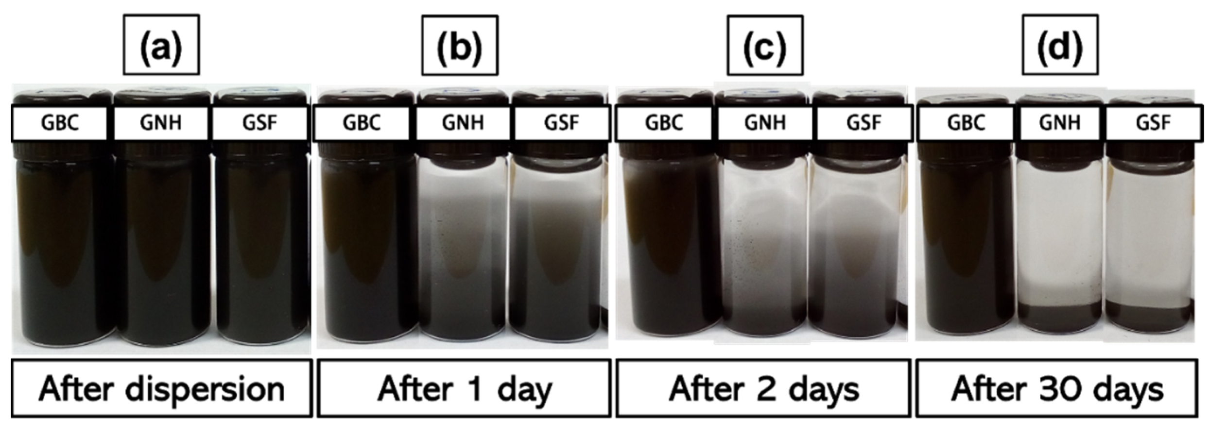
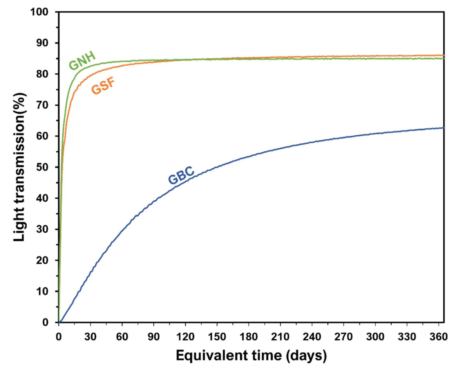
  • The stability of the GBC particles dispersed in POE oil was superior to that of the GSF and GNH particles. Even after an equivalent time of one year, the GBC particles remained suspended in the oil.
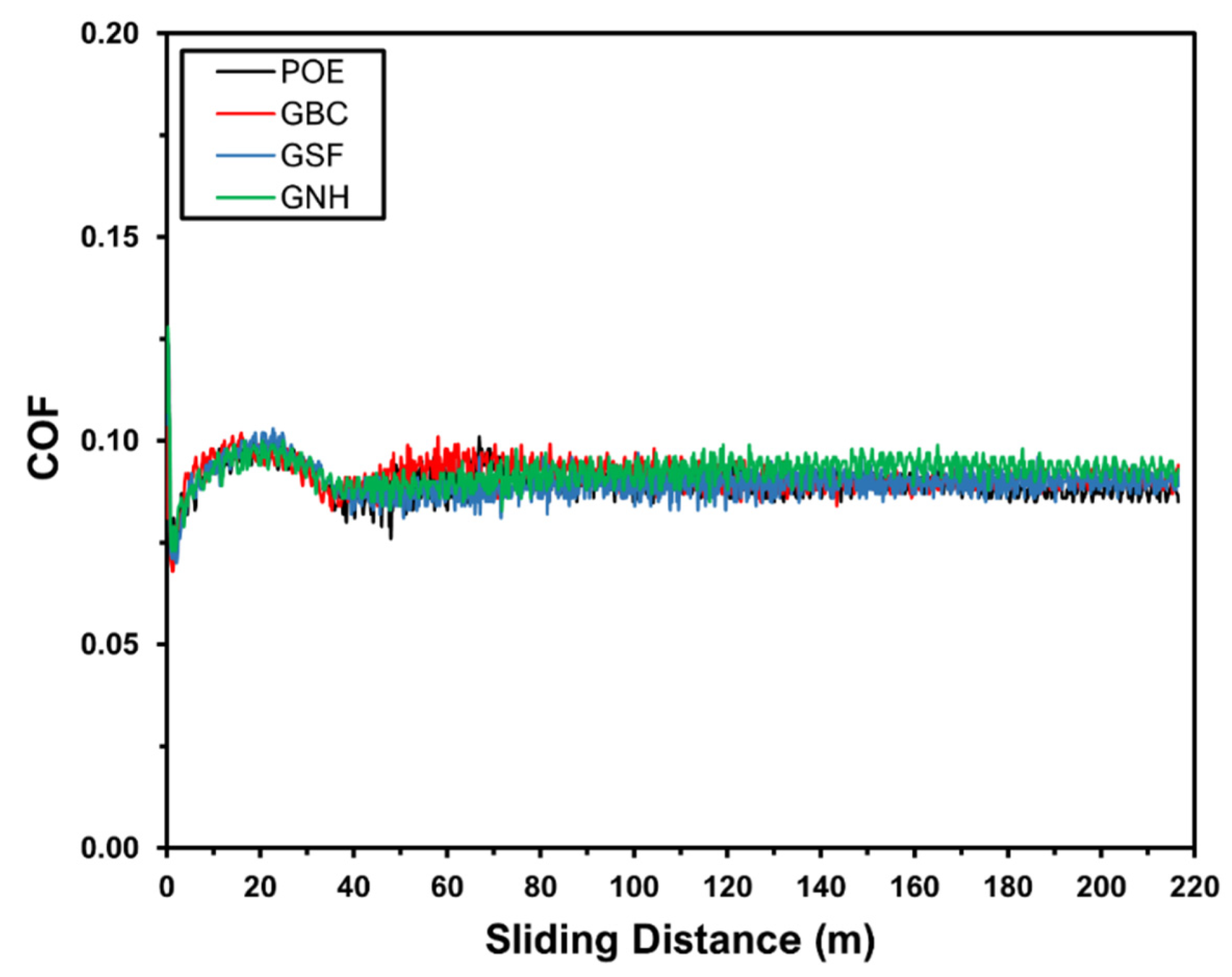
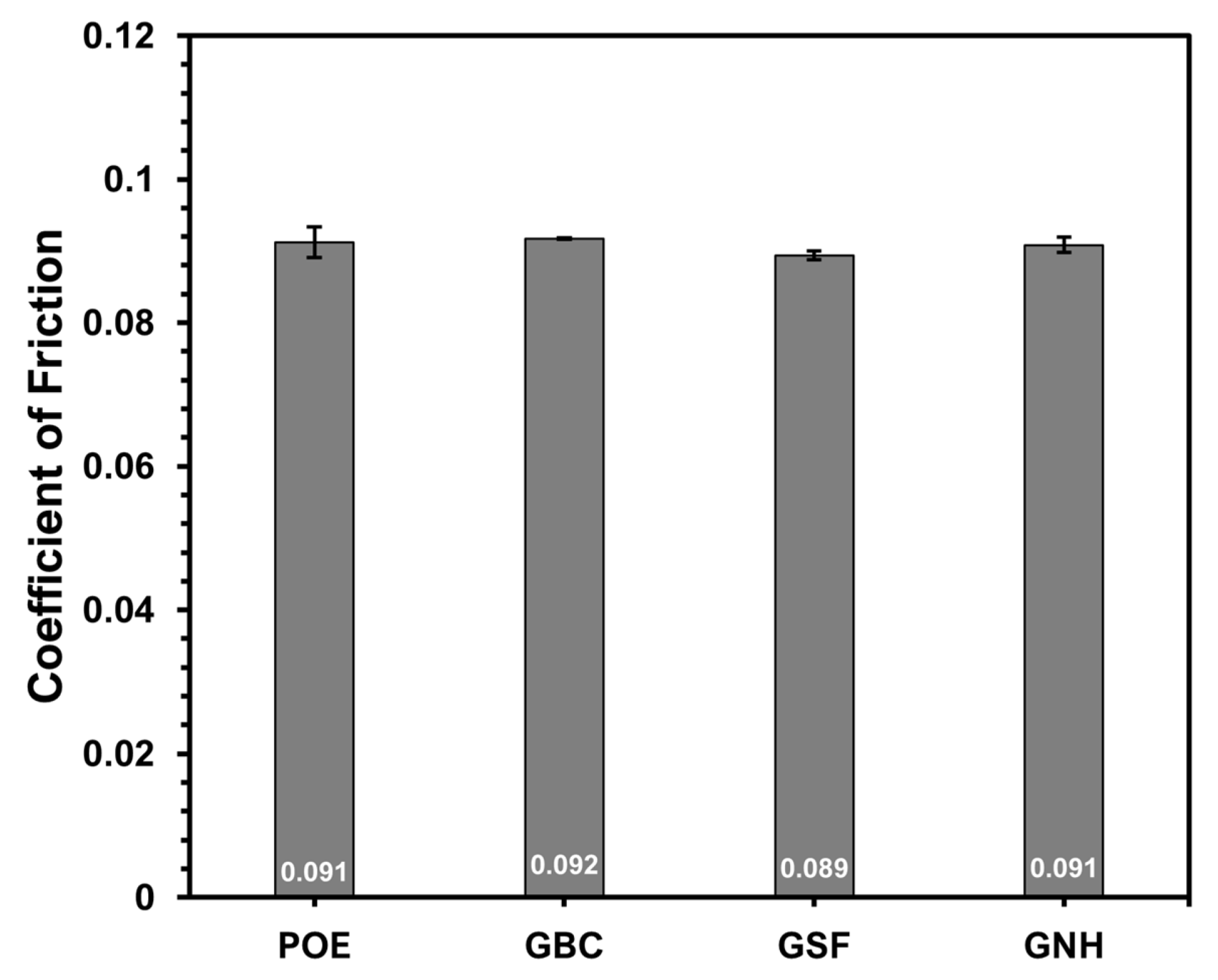
  • None of the particles was able to significantly modify the friction coefficient of the tribological system used in this work. This was probably because the POE oil, even in the severe conditions tested, still controlled the friction coefficient.
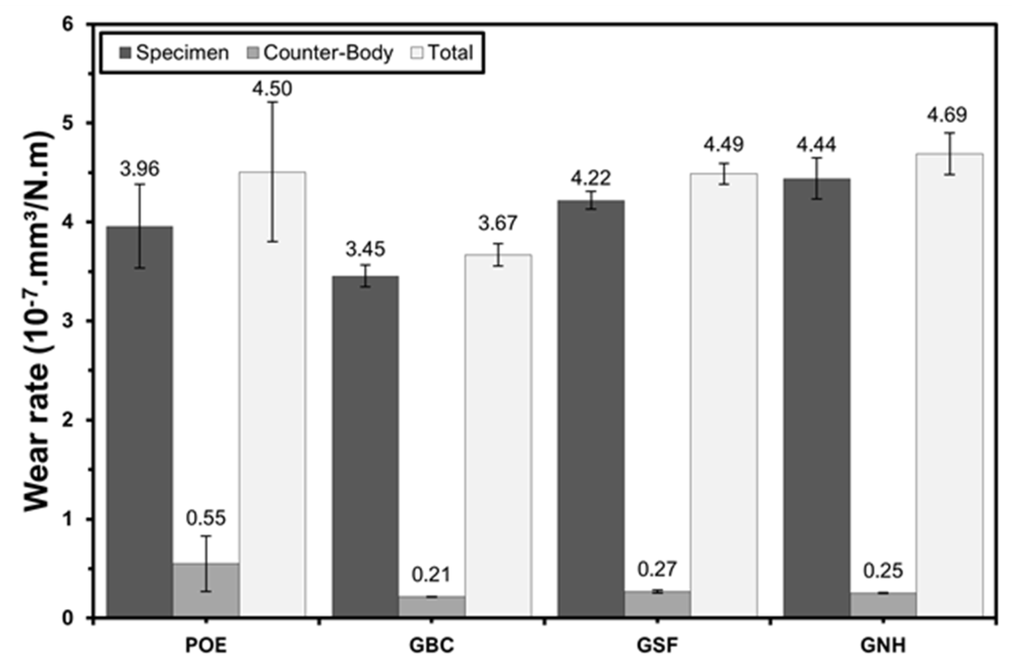
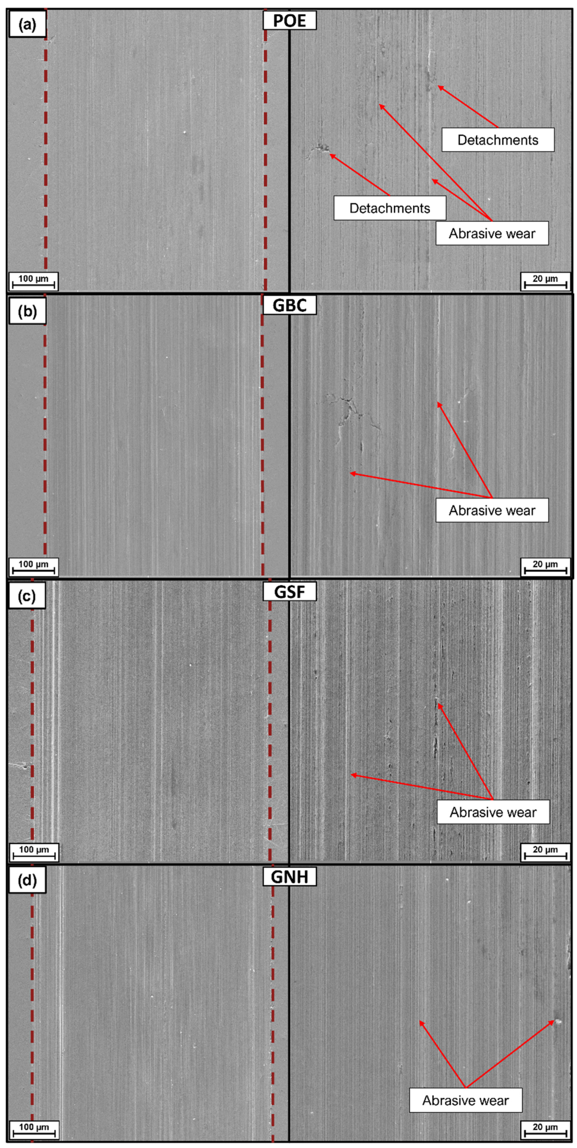
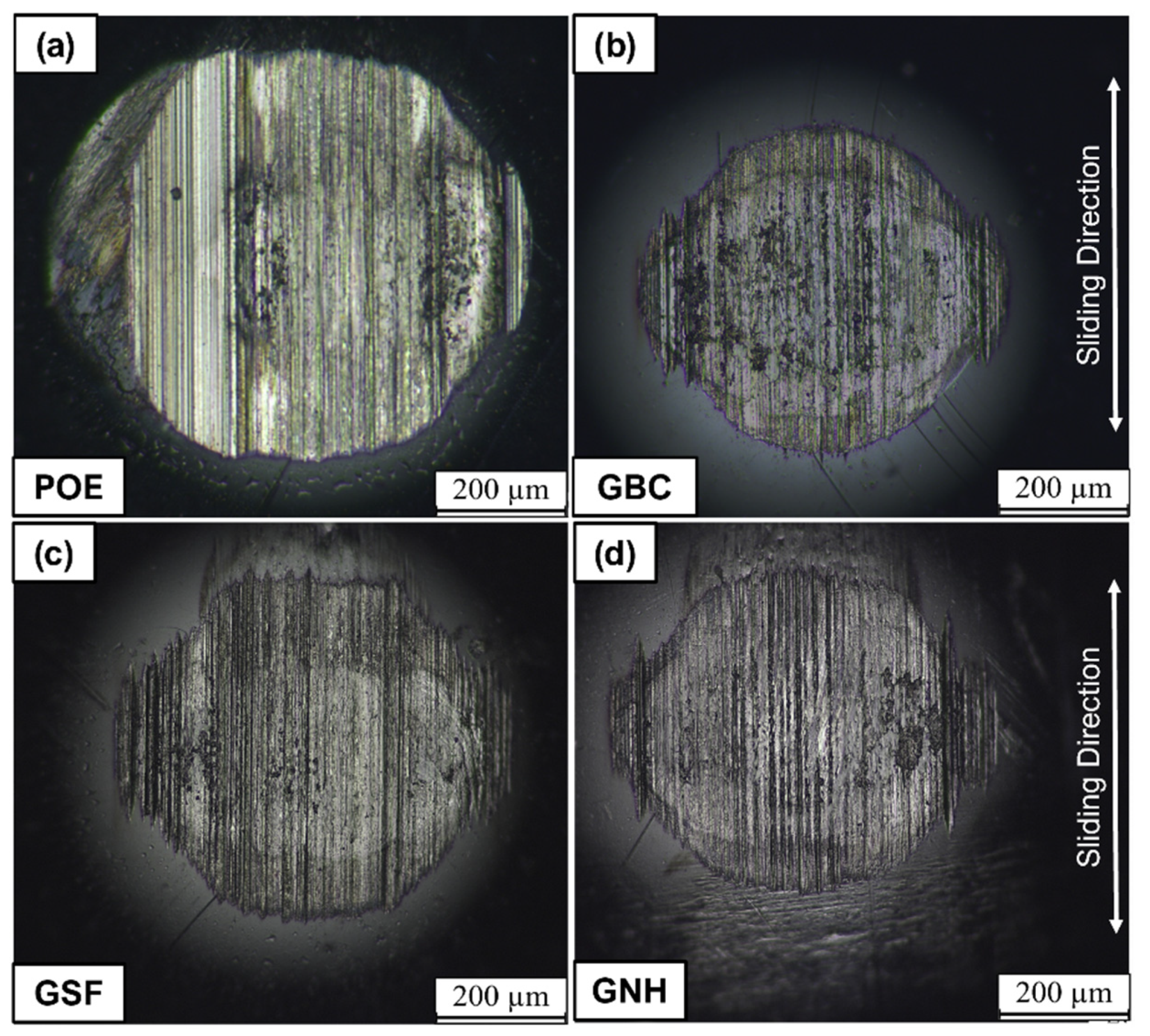
  • However, adding the particles in the POE oil reduced the wear rate on the counter-bodies by a value between 50 and 60%. Therefore, the only carbon material that reduced the total wear of the system wear was GBC.
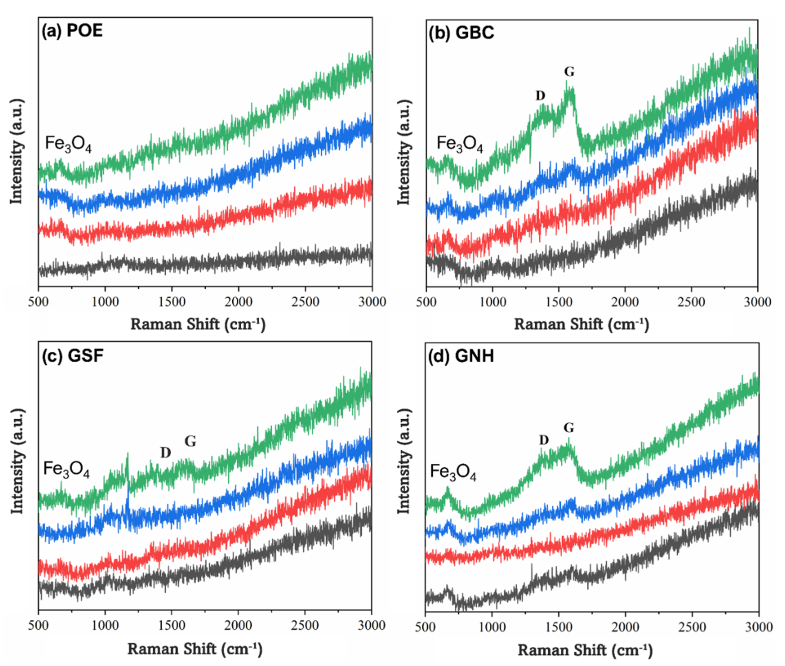
  • The superior performance of GBC as a lubrication additive may be associated with its higher stability in the POE oil, which prevents the formation of agglomerates and facilitates its penetration in the contact interface. In addition, the higher level of disorder in the crystalline structure of this type of particle may enable the formation of carbon-rich tribolayers on surfaces.

Author Contributions

Investigation, G.A.L. and G.O.N.; writing—original draft, G.O.N. and D.B.S.; methodology, J.D.B.d.M. and C.B.; writing—review and editing, J.D.B.d.M. and C.B.; conceptualisation, J.D.B.d.M., C.B. and A.N.K.; supervision, A.N.K.; funding acquisition, A.N.K. All authors have read and agreed to the published version of the manuscript.

Funding

This research was funded by Brazilian Research and Development Foundation (FUNDEP), grant number 21.062*25 (2018–2021).

Data Availability Statement

The data presented in this study are available on request from the corresponding author.

Acknowledgments

The authors acknowledge the following Brazilian agencies for funding this research: CNPq, CAPES, Fundep, and Nidec/Embraco. We also thank the LCME-UFSC for technical support.

Conflicts of Interest

The authors declare no conflict of interest.

References

  1. ENERDATA. Total energy consumption |Global Energy Statistical Yearbook 2020| Enerdata. 2020. Available online: https://yearbook.enerdata.net/total-energy/world-consumption-statistics.html (accessed on 15 December 2022).
  2. Holmberg, K.; Kivikytö-Reponen, P.; Härkisaari, P.; Valtonen, K.; Erdemir, A. Global energy consumption due to friction and wear in the mining industry. Tribol Int. 2017, 115, 116–139. [Google Scholar] [CrossRef]
  3. Holmberg, K.; Erdemir, A. The impact of tribology on energy use and CO2 emission globally and in combustion engine and electric cars. Tribol Int. 2019, 135, 389–396. [Google Scholar] [CrossRef]
  4. Holmberg, K.; Erdemir, A. Influence of tribology on global energy consumption, costs and emissions. Friction 2017, 5, 263–284. [Google Scholar] [CrossRef] [Green Version]
  5. De Mello, J.D.B.; Binder, C.; Binder, R.; Klein, A.N. Effect of precursor content and sintering temperature on the scuffing resistance of sintered self lubricating steel. Wear 2011, 271, 1862–1867. [Google Scholar] [CrossRef]
  6. Erdemir, A. Review of engineered tribological interfaces for improved boundary lubrication. Tribol Int. 2005, 38, 249–256. [Google Scholar] [CrossRef]
  7. Studt, P. Boundary lubrication: Adsorption of oil additives on steel and ceramic surfaces and its influence on friction and wear. Tribol Int. 1989, 22, 111–119. [Google Scholar] [CrossRef]
  8. Canter, B.N. Special Report: Trends in extreme pressure additives. Tribol. Lubr. Technol. 2007, 63, 10–12; 14–18. [Google Scholar]
  9. Anand, A.; Irfan Ul Haq, M.; Vohra, K.; Raina, A.; Wani, M.F. Role of Green Tribology in Sustainability of Mechanical Systems: A State of the Art Survey. Mater Today Proc. 2017, 4, 3659–3665. [Google Scholar] [CrossRef]
  10. Wong, V.W.; Tung, S.C. Overview of automotive engine friction and reduction trends–Effects of surface, material, and lubricant-additive technologies. Friction 2016, 4, 1–28. [Google Scholar] [CrossRef] [Green Version]
  11. Tang, Z.; Li, S. A review of recent developments of friction modifiers for liquid lubricants (2007-present). Curr Opin Solid State Mater Sci. 2014, 18, 119–139. [Google Scholar] [CrossRef]
  12. Bordignon, R.; Salvaro, D.; Binder, C.; Klein, A.N.; Drago, V.; de Mello, J.D.B. Tribological Behaviour of Plasma-Functionalized Graphene as Low-Viscosity Oil Additive. Tribol. Lett. 2018, 66, 114. [Google Scholar] [CrossRef]
  13. Saxena, N.D.; Chauhan, N.R. Nanomaterial in Lubricants—A Real Approach; Lecture Notes in Mechanical Engineering; Springer: Singapore, 2019; pp. 847–854. [Google Scholar] [CrossRef]
  14. Pierson, H.O. Handbook of Carbon, Graphite, Diamond and Fullerenes: Properties, Processing and Applications; William Andrew: Norwich, NY, USA, 1993. [Google Scholar]
  15. Zhai, W.; Srikanth, N.; Kong, L.B.; Zhou, K. Carbon nanomaterials in tribology. Carbon 2017, 119, 150–171. [Google Scholar] [CrossRef]
  16. Wang, H.; Gao, Q. Synthesis, characterization and energy-related applications of carbide-derived carbons obtained by the chlorination of boron carbide. Carbon 2009, 47, 820–828. [Google Scholar] [CrossRef]
  17. Georgakilas, V.; Perman, J.A.; Tucek, J.; Zboril, R. Broad Family of Carbon Nanoallotropes: Classification, Chemistry, and Applications of Fullerenes, Carbon Dots, Nanotubes, Graphene, Nanodiamonds, and Combined Superstructures. Chem. Rev. 2015, 115, 4744–4822. [Google Scholar] [CrossRef]
  18. Schoonheydt, R.A.; Pinnavaia, T.O.M.; Lagaly, G.; Gangas, N.; Kiel, È.; Chemie, È.A. ADVANCED MATERIALS SUBCOMMITTEE * Pillared clays and pillared layered solids (Technical Report) Abstract: Pillaring is a commonly used procedure to transform a layered crystalline inorganic Layered compound. Pure Appl. Chem. 1999, 71, 2367–2371. [Google Scholar] [CrossRef]
  19. Chouhan, A.; Mungse, H.P.; Sharma, O.P.; Singh, R.K.; Khatri, O.P. Chemically functionalized graphene for lubricant applications: Microscopic and spectroscopic studies of contact interfaces to probe the role of graphene for enhanced tribo-performance. J. Colloid Interface Sci. 2018, 513, 666–676. [Google Scholar] [CrossRef]
  20. Ismail, N.A.; Bagheri, S. Highly oil-dispersed functionalized reduced graphene oxide nanosheets as lube oil friction modifier. Mater. Sci. Eng. B Solid-State Mater. Adv. Technol. 2017, 222, 34–42. [Google Scholar] [CrossRef]
  21. Chun, Y.; Lim, D. Carbide derived carbon: From growth to tribological application. J. Ceram. Soc. Jpn. 2014, 122, 577–585. [Google Scholar] [CrossRef] [Green Version]
  22. Rivera, N.A.; Neves, G.O.; Giacomelli, R.O.; Salvaro, D.; Binder, C.; Klein, A.N.; de Mello, J.B.D. Dry tribological performance of nanostructured 2D turbostratic graphite particles derived from boron and chromium carbides. Wear 2021, 477, 2–11. [Google Scholar] [CrossRef]
  23. Neves, G.O.; Araya, N.; Biasoli de Mello, J.D.; Binder, C.; Klein, A.N.; Aguilar, C. Synthesis of nanostructured carbon derived from the solid-state reaction between iron and boron carbide. Mater. Chem. Phys. 2022, 276, 125396. [Google Scholar] [CrossRef]
  24. Spear, J.C.; Ewers, B.W.; Batteas, J.D. 2D-nanomaterials for controlling friction and wear at interfaces. Nano Today 2015, 10, 301–314. [Google Scholar] [CrossRef] [Green Version]
  25. Senatore, A.; Agostino, V.D.; Petrone, V.; Ciambelli, P.; Sarno, M. Graphene Oxide Nanosheets as Effective Friction Modifier for Oil Lubricant: Materials, Methods, and Tribological Results. ISRN Tribol. 2013, 2013, 425809. [Google Scholar] [CrossRef] [Green Version]
  26. Lee, C.G.; Hwang, Y.J.; Choi, Y.M.; Lee, J.K.; Choi, C.; Oh, J.M. A study on the tribological characteristics of graphite nano lubricants. Int. J. Precis. Eng. Manuf. 2009, 10, 85–90. [Google Scholar] [CrossRef]
  27. Kogovšek, J.; Kalin, M. Various MoS2-, WS2- and C-based micro- and nanoparticles in boundary lubrication. Tribol. Lett. 2014, 53, 585–597. [Google Scholar] [CrossRef]
  28. Gupta, M.K.; Bijwe, J. A complex interdependence of dispersant in nano-suspensions with varying amount of graphite particles on its stability and tribological performance. Tribol. Int. 2020, 142, 105968. [Google Scholar] [CrossRef]
  29. Huang, H.D.; Tu, J.P.; Gan, L.P.; Li, C.Z. An investigation on tribological properties of graphite nanosheets as oil additive. Wear 2006, 261, 140–144. [Google Scholar] [CrossRef]
  30. Xue, C.Y.; Wang, S.R.; Leng, J.F.; Wang, Y.; Wang, G.Q. Tribological Performance of Modified Flocculent Graphite as Lubricant Additives. Surf. Rev. Lett. 2020, 27, 1950108. [Google Scholar] [CrossRef]
  31. Ali, I.; Basheer, A.A.; Kucherova, A.; Memetov, N.; Pasko, T.; Ovchinnikov, K.; Pershin, V.; Kuznetsov, D.; Galunin, E.; Grachev, V.; et al. Advances in carbon nanomaterials as lubricants modifiers. J. Mol. Liq. 2019, 279, 251–266. [Google Scholar] [CrossRef]
  32. Cheng, W.L.; Mei, B.J.; Liu, Y.N.; Huang, Y.H.; Yuan, X.D. A novel household refrigerator with shape-stabilized PCM (Phase Change Material) heat storage condensers: An experimental investigation. Energy 2011, 36, 5797–5804. [Google Scholar] [CrossRef]
  33. Boeng, J.; Melo, C. Mapping the energy consumption of household refrigerators by varying the refrigerant charge and the expansion restriction. Int. J. Refrig. 2014, 41, 37–44. [Google Scholar] [CrossRef]
  34. Woodward, M.; Berry, C. EIA’s residential energy survey now includes estimates for more than 20 new end uses. EIA Resid. Energy Consum. Surv. 2018, 1–2. Available online: https://www.eia.gov/todayinenergy/detail.php?id=36412 (accessed on 30 January 2023).
  35. Neves, G.O.; Araya, N.; de Mello, J.D.B.; Binder, C.; Klein, A.N. Synthesis, Characterization and Performance of Nanostructured 2D Turbostratic Graphite Particles Derived from the Solid-State Reaction Between Carbides. Mater. Res. Bull. 2022, 151, 111826. [Google Scholar] [CrossRef]
  36. Dias, H.W.J.; Medeiros, A.B.; Binder, C.; Neto, J.B.R.; Klein, A.N.; de Mello, J.D.B. Tribological evaluation of turbostratic 2d graphite as oil additive. Lubricants 2021, 9, 43. [Google Scholar] [CrossRef]
  37. Detloff, T.; Sobisch, T.; Lerche, D. Particle size distribution by space or time dependent extinction profiles obtained by analytical centrifugation. Part. Part. Syst. Charact. 2006, 23, 184–187. [Google Scholar] [CrossRef]
  38. Cançado, L.G.; Takai, K.; Enoki, T.; Endo, M.; Kim, Y.A.; Mizusaki, H.; Speziali, N.; Jorio, A.; Pimenta, M.A. Measuring the degree of stacking order in graphite by Raman spectroscopy. Carbon 2008, 46, 272–275. [Google Scholar] [CrossRef] [Green Version]
  39. Pimenta, M.A.; Dresselhaus, G.; Dresselhaus, M.S.; Cançado, L.G.; Jorio, A.; Saito, R. Studying disorder in graphite-based systems by Raman spectroscopy. Phys. Chem. Chem. Phys. 2007, 9, 1276–1291. [Google Scholar] [CrossRef]
  40. Martins Ferreira, E.H.; Moutinho, M.V.O.; Stavale, F.; Lucchese, M.M.; Capaz, R.B.; Achete, C.A.; Jorio, A. Evolution of the Raman spectra from single-, few-, and many-layer graphene with increasing disorder. Phys. Rev. B Condens. Matter Mater. Phys. 2010, 82, 125429. [Google Scholar] [CrossRef] [Green Version]
  41. Prusty, K.; Barik, S.; Swain, S.K. A Corelation Between the Graphene Surface Area, Functional Groups, Defects, and Porosity on the Performance of the Nanocomposites. In Functionalized Graphene Nanocomposites and Their Derivatives: Synthesis, Processing and Applications; Elsevier: Amsterdam, The Netherlands, 2018; pp. 265–283. [Google Scholar] [CrossRef]
  42. Fang, B.; Li, J.; Zhao, N.; Shi, C.; Ma, L.; He, C.; He, F.; Liu, E. Boron doping effect on the interface interaction and mechanical properties of graphene reinforced copper matrix composite. Appl. Surf. Sci. 2017, 425, 811–822. [Google Scholar] [CrossRef]
  43. Neves, G.O.; Salvaro, D.B.; Bendo, T.; Consoni, D.R.; de Mello, J.D.B.; Binder, C.; Klein, A.N. Carbon Structures and Tribological Properties of Fe-C-SiC Self-Lubricating Metal Matrix Composites Prepared with α/β-SiC Polytypes. Lubricants 2022, 10, 112. [Google Scholar] [CrossRef]
  44. Dai, W.; Kheireddin, B.; Gao, H.; Liang, H. Roles of nanoparticles in oil lubrication. Tribol. Int. 2016, 102, 88–98. [Google Scholar] [CrossRef]
Figure 1. Carbon-based particles morphology, (a) 2D turbostratic graphite derived from B4C-Cr3C2 (GBC), (b) 2D turbostratic graphite derived from SiC-Fe (GSF), (c) NH3-functionalized graphene (GNH).
Lubricants 11 00155 g001
Figure 2. Procedure for dispersing carbon-based additive particles in POE oil. (a) Adding solid lubricants; (b) ultrasonication; (c) suspension collection; (d) vial for suspension stability analysis.
Lubricants 11 00155 g002
Figure 3. Method for quantifying worn volumes in counter-body and specimen. Counter-body: (a) schematic; (b) wear scar; (c) geometrical parameters; specimen: (d) specimen’s wear track; (e) Specimen’s average worn area and profile.
Lubricants 11 00155 g003
Figure 4. Exemplary Raman spectra of the carbon particles GBC, GSF and GNH.
Lubricants 11 00155 g004
Figure 5. Digital images of GBC, GNH and GSF particles dispersed in POE oil (a) after dispersion, (b) after 1 day, (c) after 2 days, (d) after 30 days. Dispersion concentration, 0.05 wt.%.
Lubricants 11 00155 g005
Figure 6. Evolution of the light transmission profiles. (a) POE + GBC, (b)POE + GSF, (c) POE + GNH.
Lubricants 11 00155 g006
Figure 7. Light transmission integral along the cuvette as a function of equivalent time.
Lubricants 11 00155 g007
Figure 8. Typical evolution of the friction coefficient as a function of distance during constant load tests.
Lubricants 11 00155 g008
Figure 9. Average friction coefficient during constant load tests for each lubrication condition.
Lubricants 11 00155 g009
Figure 10. Wear rate from constant normal load tests with POE, POE + GBC, POE + GSF and POE + GNH.
Lubricants 11 00155 g010
Figure 11. Secondary electron SEM images of wear tracks of specimens lubricated with POE (a), POE + GBC (b), POE + GSF (c) and POE + GNH (d).
Lubricants 11 00155 g011
Figure 12. Typical wear marks on the counter-bodies during constant normal load tests with (a) POE, (b) POE + GBC, (c) POE + GSF and (d) POE + GNH lubrication. Images obtained by optical microscopy.
Lubricants 11 00155 g012
Figure 13. Raman spectra of specimens wear tracks of POE (a), POE + GBC (b), POE + GSF (c) and POE + GNH (d).
Lubricants 11 00155 g013
Disclaimer/Publisher’s Note: The statements, opinions and data contained in all publications are solely those of the individual author(s) and contributor(s) and not of MDPI and/or the editor(s). MDPI and/or the editor(s) disclaim responsibility for any injury to people or property resulting from any ideas, methods, instructions or products referred to in the content.

