Article

The Optimal Design Model for a New Type of Scraper and Research on Its Material Properties

1
Energy and Mining Engineering, Shandong University of Science and Technology, Qingdao 266590, China
2
Mine Disaster Prevent & Control Ministry, Shandong University of Science and Technology, Qingdao 266590, China
*
Authors to whom correspondence should be addressed.
Lubricants 2023, 11(4), 171; https://doi.org/10.3390/lubricants11040171
Submission received: 14 March 2023 / Revised: 30 March 2023 / Accepted: 6 April 2023 / Published: 10 April 2023
(This article belongs to the Special Issue Assessment of Adhesive Wear)

Abstract

:
Mining scrapers as an important part of scraper conveyors are highly prone to wear and fatigue failure. A new scraper capable of turning sliding friction into rolling friction was designed to limit wear and reduce failure rate. To determine the safety and reliability of the new scraper, numerical pulling force measurement was conducted on its physical model and finite element analysis was performed on its 3D model based on SolidWorks Simulation. The results were then compared with data of the traditional scraper. Numerical pulling force measurement results indicated impressively lower friction for the new scraper. Stress, strain, and displacement distributions obtained by static stress analysis based on SolidWorks Simulation proved conformance with the strength and deflection standards. Damage percentage and total life nephograms yielded from fatigue analysis indicated no significant life reduction. Numerical pulling force measurement combined with analysis based on SolidWorks Simulation can help reduce the production cost and development cycle. It plays a great role in determining the safety, reliability, and stability of the new scraper.

1. Introduction

Mining scrapers are an important part of scraper conveyors. They are connected with beams, bolts, chains, and sprockets to convey materials. They are also one of the scraper conveyor parts with the highest failure rate—statistics showed a failure rate of as high as 35.8% [1]. On fully mechanized mining faces, scrapers can often break or fall off, preventing the scraper conveyor from further operation and bringing the production across the mining face to a halt.
Scrapers fail mainly because of wear and fatigue. There is a gap between the conveyor trough and the scraper, into which coal gangue often slips and rubs against the scraper and the chain, increasing the friction force of the scraper conveyor. The scraper itself is in close contact with the conveyor trough; its sliding friction with the trough further intensifies the wear. Excessive drop height of the coal or excessive size of the coal blocks will cause the maximum stress in some areas of the scraper to exceed the permissible limit for the forging material, leading to strength failure and breakage.
The failure rate of a scraper can be reduced in two ways. One is to optimize the scraper chain so that it has good tension against violent shock. The other is to improve the scraper’s own material and structure. On the one hand, this can change the contact form between the scraper and the conveyor trough to reduce the scraper–trough friction, limit wear and increase the service life of the scraper. On the other hand, it can optimize the scraper structure with anti-shock, corrosion-resistant material to increase bearing capacity.
So far, researches on the failure rate of scraper conveyors are primarily focused around the optimization of the scraper chain. Dolipski et al., designed an automatic initial chain tension adjustment system using an own mathematical conveyor model of a scraper conveyor and the ASTEN algorithm [2]. Liu et al., examined the causes of scraper chain breakage from material and hardness perspectives [3,4]. Szewerda et al., considered the impact of angle and inclination of a scraper conveyor on its operation dynamics and described ways in which the longitudinal inclination of a conveyor affects chain loosening [5]. Wang et al., performed several rounds of wear test to investigate the wear behavior and mechanism of the ring chain of scraper conveyors [6,7,8].
In addition, Fedorko proposed an innovative approach to partially or completely eliminate unstable working areas by measuring the relevant parameters of a special steel abrasive transported by scraper conveyor [9]. Szurgacz pointed out that in the era of Industry 4.0, green economy, and sustainable development, it is necessary to properly monitor and control the operation parameters of mechanical supports in longwall mining faces. He proposed a solution aimed at reducing the working time of operators in the power support section. His analysis and research results can provide practical help for shell users to improve reliability and achieve optimal performance [10]. Molnar pointed out that rubber conveyor belts are important components of transportation chains in many industries, as they can remove adhered goods from the belts and reduce losses of these resources in transportation process. The frictional contact between the belt and scraper is very important, as it is often a source of wear and unexpected energy consumption. He proved that friction and wear have a strong dependence on the alignment angle between the bolt and the belt [11].
These authors systematically investigated the scraper chain with respect to the installation design, operating state monitoring and failure analysis, offering groundbreaking outcomes in theory as well as optimized designs for real application. Nevertheless, most of the studies are limited to the optimization of scraper conveyors in terms of the scraper chain alone. Few have considered the synergy between the scraper chain and the scraper. As one of the key contributors to the efficiency and reliability of a scraper conveyor, an optimization plan is also needed for the scraper as a supplement to the already optimized design of the scraper chain so that these components can help improve the capacity and efficiency of the scraper conveyor together.
Of course, some attempts have already been made by some authors in this respect. For example, Davydov SY elaborated on the construction and operation of tubular scraper conveyors (TSCs) and comparatively evaluated the technical characteristics of TSCs [12]. Li S presented a dynamic reliability model of scraper chains based on fretting wear process and proposed an appropriate structural optimization method [13,14]. Marinelli M proposed a new algorithmic optimization method incorporating the golden section search and the bisection algorithm and proved that the new method can effectively reduce the loading cost [15]. Chai improved the structure of the groove rim of a transport chute and compared the stress distribution of the structure before and after improvement using ANSYS software(Ansys 2019 R2, ANSYS Corporation, Canonsburg, PA, USA). The modified structure reduced stress concentration and improved the structural strength and reliability of the transport chute [16]. Chen studied the structural form of the high-speed shaft of the planetary gear reducer of a scraper conveyor on a coal mine underground working face. Based on the working conditions of the reducer, he analyzed the advantages and disadvantages of several different structural forms of high-speed shafts, providing reference for its structural design [17]. Hua pointed out that Ultra-wideband (UWB) is a promising wireless radio frequency technology with centimeter-level ranging capabilities. She used an UWB-based extended Kalman filter (EKF) to locate and track the displacement of the scraper blade at both ends, achieving the purpose of monitoring the health of the chain [18].
These studies are relatively mature and involve performance testing or dynamic monitoring of existing scrapers on the theoretical dimension. They revealed the mechanical properties of scrapers, provided detailed description of their micro mechanical characteristics and wear conditions during operation, reflected their operating mechanism on a dynamic basis, and rebuilt their dynamic models in the operation of a scraper conveyor [19,20]. However, as they failed to adjust the overall structure of the scraper, the practical application result of their optimization plans is less than perfect. There are three omissions as follows:
(1)
These studies focus on the independent research of scraper chains and transport chutes, lacking a comprehensive analysis of the transportation system (scraper chain–scraper–transport chute) of scraper conveyors.
(2)
As an intermediate part connecting the scraper chain and transport chute, there are few existing researches on the optimization design of this single component of scraper.
(3)
In the process of applying these theories to practical design, designers or engineers often pursue simplified designs and emphasize simplifying product assembly steps and reducing costs by reducing the number of parts. The interaction design between the transport chute and scraper is lacking because the mutual influence between the scraper chain, transport chute, and scraper is not considered. There is a lack of understanding that adding appropriate parts in the actual operation of mechanical products can greatly reduce the product’s use and maintenance costs, although it may increase manufacturing costs.
The scraper of a scraper transporter may experience the following failure modes and types: (1) Scraper wear: The scraper may wear down over time, resulting in reduced conveying capacity. (2) Scraper breakage or distortion: The scraper may break or become distorted due to external forces or fatigue. (3) Scraper detachment: Due to excessive wear or improper installation, the scraper may detach from the bearing or spring support, causing the operation to be interrupted. (4) Scraper material jamming: If the gap between the scraper and the conveyed material is too small, or if the conveyed material contains large pieces of material, the scraper may become stuck and cannot operate normally. (5) Transmission mechanism failure: The transmission mechanism of the scraper transporter may experience problems such as motor or reducer failure, causing the scraper to malfunction. Usually, the failure and fault types of the scraper will be shown together with other faults of the scraper transporter, as shown in Table 1.
From the data in Table 1, it can be seen that the failure rate of scrapers is relatively high. Therefore, this paper presents a new scraper model, which adds a roller structure to the traditional scraper to turn sliding friction into rolling friction and effectively reduce wear failure. To prove its advantages, pulling force experiment was conducted on the physical model of the new scraper to confirm effective reduction in friction force. Based on the reliability theory, static stress and fatigue analysis were performed on the new scraper using SolidWorks Simulation, which yielded the stress, strain, and displacement distributions of the new scraper. The deformation-prone portions of the new scraper were evaluated theoretically to verify whether it is constructed to the required deflection and strength.

2. Experimental Section

2.1. Sample Preparation

A type II scraper shown in Figure 1 is used as the base body of the modified new scraper. The ring chain size (d × p) is 48 mm × 152 mm; the trough width is 1200 mm; the length (L) is 1184 mm; the chain center distance (A) is 280 ± 1.0 mm; the hole spacing (B) is 520 ± 0.75 mm; the bolt hole diameter (d1) is 33 mm.
Scraper modification covers the base body, support body, and rolling bearing. A group of holes are drilled on the contact face between the scraper and the conveyor trough, as shown in Figure 2. A support body is made from polyurethane material and combined with the rolling bearing [21,22]. The support body with the rolling bearing is then inserted into the scraper by interference fit before a rolling ball and auxiliary balls are placed into the rolling bearing.
The support body is made from high molecule polyurethane material. The rolling bearing is mounted into the support body in a removable manner, as shown in Figure 3a. The high molecule polyurethane material or similar elastic material must satisfy or possess the following properties [23,24], which is shown in Table 2:
The rolling groove in the rolling bearing is processed into a semi-closed structure such that the rolling ball is in rolling contact with the conveyor trough while the remaining part of the rolling ball remains in the rolling groove, as shown in Figure 3b.
To ensure better stability and reliability, a layer of finer auxiliary balls is designed between the rolling groove and the rolling ball to produce secondary rolling contacts [25]. Both the balls and the rolling bearing are made from high strength metals such as stainless material [26,27,28]. The rolling ball is 6–20 mm in diameter; the auxiliary balls are 2–5 mm in diameter. The final model is shown in Figure 4.

2.2. Newtonian Mechanics Experiment

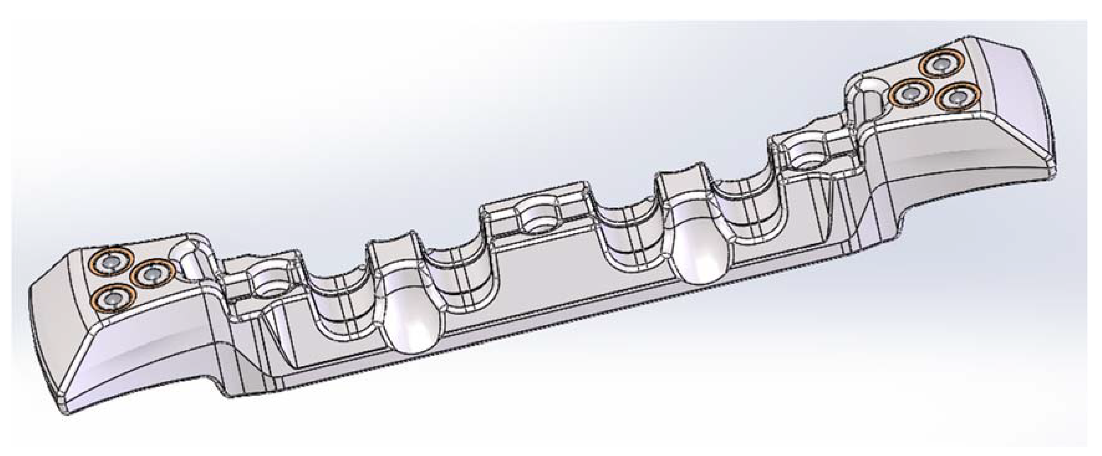
To quantitatively prove the advantages of the new scraper, the pulling force of the physical models of the new scraper in Figure 5a and the traditional scraper in Figure 5b are numerically measured before the measurement results are compared.
The Zhiqu DS2 series digital push–pull gauge(Dongguan Zhiqu Precision Instrument Co., Ltd., Dongguan, China), which is shown in Figure 5c, is a multipurpose high-accuracy push–pull load tester designed for the push–pull load testing, insertion–withdrawal force testing, and destructive force experiment of various products [29]. The DS2 series features high accuracy, long service life, small volume, long standby time, and easy operation. Armed with professional software and a USB data cable, these gauges can connect with instruments or computer to observe the test data and results [30,31,32].
In real application, the new scraper is jointly driven by the push rod and the chain. In the numerical pulling force measurement, the pushing force of the push rod and the pulling force of the chain are integrated into the pulling force of the pull gauge on the physical model of the scraper. Plastic tape is used to simulate the scraper chain.
On the comprehensive mining face, there are coal debris, water, and other substances on the transport groove, and the coal distribution on the transport groove is uneven. These factors affect the moving speed of the scraper and cause it to not move at a constant speed. To simulate the effect of these factors, we moved the scraper by pulling the measuring sensor.
Pulling force is gradually applied to the physical model. The software system 3.0 of the Zhiqu DS2 series push–pull gauge is used to record pulling force development. The experiment process is shown in Figure 6. On real coal mining faces, as the conveyor trough is not an absolute plane and due to presence of coal debris, the pulling and pushing forces on the scraper are not a constant value. In the simulation experiment, the pulling force on the scraper during stable operation is unstable, too. Therefore, in the simulation experiment, the pull gauge is set to “Peak”. The first peak pulling force obtained can be regarded as the instantaneous driving force received by the scraper [33,34]. When the pulling force peaks, the reading of maximum pulling force can be regarded as the driving force received by the new scraper during stable operation. After that, the readings can be taken again while the scraper works stably. However, as the readings at that time are unstable, the average can be used as the ideal stress condition.
The specific tension measurement scheme is as follows:
(1)
Prepare the experimental equipment. The required experimental equipment includes: the new scraper, traditional scraper, digital force gauge (with a range of 500 N), lever, plastic tape, and camera.
(2)
Place the new scraper horizontally on the test bench, and use plastic tape to simulate the chain. Tie (stick) it to the new scraper. The other end of the plastic tape should be connected to the lever. The folding binding method is used for the plastic tape, which, together with the lever, ensures that the new scraper is subjected to balanced and evenly distributed tension.
(3)
Stick tape in the middle of the lever and connect the force gauge. Adjust the mode of the force gauge to peak mode, slowly pull the force gauge, and observe the changes in tension. When the first peak tension value is reached, that is, when the scraper starts to move, the number displayed on the force gauge no longer changes; record the tension data at this time.

2.3. Static Stress Analysis Scheme

SolidWorks (SolidWorks 2020, Dassault Systemes, Massachusetts, USA) is a 3D CAD software developed by Dassault Systemes and widely used in mechanical design, engineering analysis and other fields. It provides comprehensive functions for modeling, assembly, drawing, etc., which can help users efficiently complete product design and testing while performing numerical analysis and simulation. In this study, to conduct finite element analysis of the new and traditional scrapers, we used SolidWorks (version 2020) for static stress analysis and fatigue analysis.
(1)
Material properties
Before starting static stress and fatigue analysis, it is necessary to define the material properties of five parts, including the modified base body, support body, rolling bearing, rolling ball, and auxiliary balls.
The modified base body is a traditional alloy steel scraper forged from 27SiMn. The material properties of the modified base body are provided in Table 3 [35].
The support body is made from high molecule polyurethane material, as shown in Figure 7. This is designed to separate the rolling bearing from the modified base body to limit direct contact and reduce wear. It can also serve as a buffer that reduces the impact on the scraper. The material properties of the support body are provided in Table 4.
The rolling bearing is forged from conventional stainless steel (1Cr18Ni9Ti). It is used to support the rolling ball and auxiliary balls. The material properties of the rolling bearing are provided in Table 5.
The rolling ball and auxiliary balls are used to reduce friction and turn sliding friction into rolling friction. These balls are made from roughly the same material. Both can be YG8 carbide balls, as shown in Figure 8. Composed mainly of ceramic (silicon nitride, Si3N4) with high hardness and wearability as well as good impact and vibration resistance, they are suitable for fabricating parts subject to high impact and vibration [36,37]. The material properties of the rolling ball and auxiliary balls are provided in Table 6.
(2)
Constraint
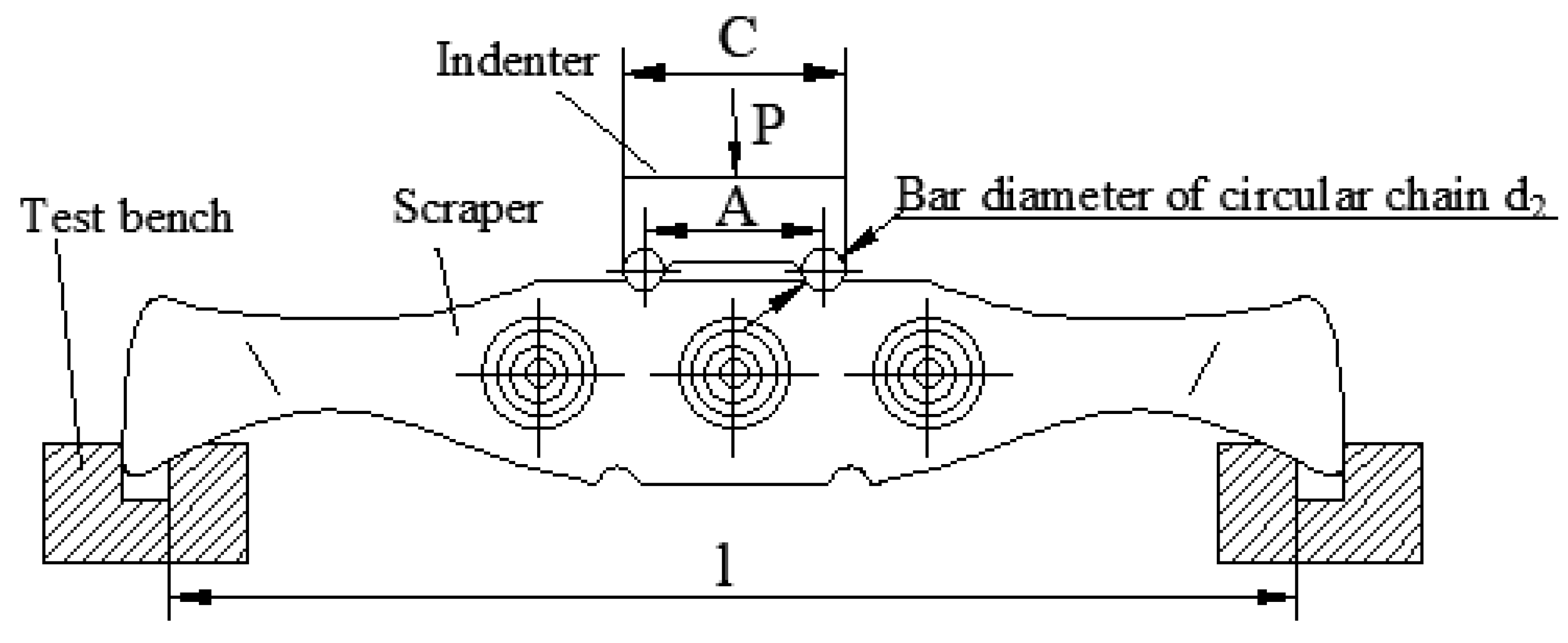
When performing finite element analysis, it is necessary to simulate the boundary conditions (displacement constraint) defined by the particular working environment (fully mechanized mining face) for the assembly (new scraper). According to national standard MT323-2005, Flight bar for twin inboard chain face conveyor, the load application type for the force–deflection test of the scraper is as shown in Figure 9.
In the Figure,
C—width of the test indenter, mm;
A—chain center distance, mm;
d2—diameter of the circular chain bar, mm;
l—experimental span, mm;
P—load, kN.
Typically, the working environment of the scraper is harsh, and it often experiences loads beyond the capacity of the material and structure, leading to fatigue, fracture, distortion, or other failures. Therefore, in the national standard MT323-2005, Flight bar for twin inboard chain face conveyor, a force–deflection test for scrapers as shown in Figure 9 is provided to check the quality and performance of scrapers.
The test procedures are as follows: (1) The test fixture should be fixed on the working surface of the testing machine, and the scraper should be placed on the test fixture. (2) The loading direction and position should follow the requirements shown in Figure 9. (3) The testing machine should be started so that the press head contacts the scraper and applies the load. (4) The load P should be increased uniformly to the specified value at a loading rate not exceeding 20 N/mm2 per second.
This test is a destructive test that requires a specified force to be applied to the scraper (with different requirements for different types of scrapers), which is large enough to cause bending displacement of the scraper. Due to practical constraints, we can only simulate this test using SolidWorks.
In finite element analysis, the test bench support can be regarded as the plane containing the constraint. The surface of the scraper in contact with this surface serves as the boundary condition, and its constraint form is a fixed geometry, as shown in Figure 10 [39]. The modified base body of the new scraper consists of a type II scraper with chain center distance = 280 ± 1.0 mm and length L = 1184 mm. According to the provisions of the national standard for scraper for double-chain scraper conveyor in MT323-2005, the experimental span l of a type II scraper with a length L of 1184 mm is 1104 mm, and the rated strength value, that is, the load P, is 560 kN, with the direction being normal, i.e., perpendicular to the force-bearing surface. Therefore, the experimental span of the new scraper is 1104 mm, which includes the five stressed faces in the model. The load is 560 kN and its direction is perpendicular to the five stressed faces in the model. The model under constraint is shown in Figure 10.
(3)
Load
The real load environment has to be defined on the finite element model [40,41]. Ideally, during coal mining, the coal fallen on the conveyor trough is evenly distributed. In finite element analysis, the load P applied by the test indenter is evenly spread on the side of the new scraper, as shown in Figure 11. According to national standard MT323-2005, Flight bar for twin inboard chain face conveyor, for a scraper with length L = 1184 mm, the experimental span should be l = 1104 mm, namely the five stressed faces in the model. The rated strength, namely load, is P = 560 kN. The direction is normal, namely perpendicular to the stressed face [42].
(4)
Model meshing
When meshing the model, it is important to choose the right mesh type and parameters according to the particular model structure and environment in question [43]. On the one hand, as the modified base body is structurally complete and represents the main stressed area, plus the structure of the rolling bearing area is important, the model can be directly meshed. This way, the mesh density will be good and the mesh parameters will be curvature based meshes. On the other hand, as twisted cells exist in the balls and the number of balls is large, it is necessary to process the balls in batch separately. This way the mesh density will be good and the mesh parameters will be curvature based meshes. The overall size for the two is 9.522 mm with a tolerance of 0.476 mm. The model meshing result is shown in Figure 12.
After completing the above steps, the prerequisite for static stress simulation is met. After simulating with SolidWorks, the displacement, stress, and strain nephogram of the new scraper can be obtained. the same procedure and analysis process are used to see what happens to the traditional scraper.

2.4. Fatigue Analysis Scheme

The forging material for the scraper is 27SiMn. 27SiMn steel is a low-carbon microalloyed steel with high strength, toughness, and fatigue life. It is a type of steel with good mechanical properties that is widely used in engineering machinery, oil pipelines, and metallurgy fields.
The fatigue characteristics of this material refer to indicators such as fatigue life and fatigue limit under repeated loads. The fatigue characteristics of this material are mainly determined by its microstructure, chemical composition, and processing hardening. Fatigue tests can be used to obtain information on the fatigue characteristics of this type of steel. Common methods for fatigue analysis include the limit state method, fatigue margin method, and stress intensity factor method. The limit state method evaluates based on the comparison of actual loads and the ultimate bearing capacity of the structure; the fatigue margin method calculates the reliability of the component based on its fatigue strength, actual load, and safety factor; and the stress intensity factor method studies and analyzes the relationship between fatigue residual life and stress intensity factors using linear elastic fracture mechanics theory.
In this study, we evaluated the fatigue life of the scraper using the fatigue margin method and described the experimental steps and parameter settings in detail. Specifically, we first established fatigue specimens according to the standard. Fatigue test results show that the fatigue limit of 27SiMn steel is usually around 400 MPa, and its hysteresis curve is similar to the S–N curve. Then, we performed finite element analysis of the scraper in SolidWorks and calculated the stress state of different parts of the scraper. Finally, we calculated the fatigue reliability of the scraper under actual working conditions using the fatigue margin calculation method. This type of fatigue analysis method can accurately assess the fatigue life of the scraper and provide reference basis for optimizing the design.
(1)
Material properties
Prior to conducting fatigue analysis, it is necessary to define the material properties of the five components, including the modified substrate, support body, rolling bearing seat, ball bearings, and auxiliary ball bearings. The material properties of these components have already been provided in the static stress analysis and will not be reiterated here.
(2)
Constraint
The constraints for fatigue analysis are the same as those for static stress analysis.
(3)
Load
According to the safety rules, a scraper should be placed along the conveyor trough of a scraper conveyor every 0.98 m [44]. The chain speed of the scraper conveyor used in a mine is 1.3 m/s. A 335 m long conveyor trough has been installed and requires 342 scrapers. The load P increases evenly to 560 kN at the rate of 2 N/mm2 per second (the cross-sectional area is the total sectional area of the ring chain used), then it is unloaded to the initial load. The ring chain size is 48 × 152 mm; the cross-sectional area is 1808.64 mm2; the total sectional area is 3617.28 mm2. Accordingly, the peak loading of the load is 154.81 N/mm2; the loading time is 7.74 s; the duration of a cycle is 523.12 s. The load variation in each cycle is calculated by
P = {         20 t ,                                                                           t 7.14         560 ,                                                                         7.14 < t 257.69 560 20 ( t 257.69 ) ,                             257.69 < t 265.43         0 ,                                                                               265.43 < t 523.12 .
Static stress analysis is the prerequisite for fatigue analysis. The material properties, load, constraint, and connection form of the new scraper model have been determined [45,46,47]. Fatigue analysis is performed using historical data with variable high and low amplitudes.
The new scraper is made of various materials including 27SiMn, stainless steel (1Cr18Ni9Ti), and high-molecule polyurethane, whose fatigue curves are not identical. To avoid lengthy and repetitive explanations while also observing confidentiality, we only present the fatigue curve of the base material (27SiMn) for the new scraper. The number of rain flow counting boxes is 25; the metric for calculating alternating stress is stress intensity (P1–P3); the average stress is corrected to Gerber. Considering that the production environment of the fully mechanized mining face is very complex, the fatigue strength reduction factor (kf) is set to 1. An S–N curve is derived from the material elastic modulus based on the ASME carbon steel curve [48,49,50]. The interpolation of the fatigue S–N curve is double log; the stress ratio is 0. Finally, the resulting fatigue data are applied to all the parts. The load curve of the material in the added event is shown in Figure 13.
The meaning of Figure 13 is as follows: at the beginning of the test, the initial load on the new scraper is 0 N. From time t = 0 s, the load is uniformly applied to the five sides of the new scraper at a rate of 20 N/mm2 per second, simulating the contact between the new scraper and coal. At time t = 7.74 s, the load on the new scraper reaches 560 kN and no longer continues to apply the load, simulating that the new scraper has carried enough coal. In the next 249.59 s, the scraper is subjected to a constant load of 560 kN, simulating the displacement of the new scraper carrying coal from the input end of the transport chute to the output end. At time t = 257.69 s, the load is uniformly unloaded at a rate of 20 N/mm2 per second, simulating the unloading of the coal by the new scraper after reaching the output end of the transport chute. Again, after 7.74 s, at time t = 265.43 s, the load on the scraper is reduced to 0 N, simulating the completion of coal unloading by the new scraper. In the next 257.69 s, the new scraper undergoes displacement without carrying any load, simulating the movement of the new scraper from the output end of the transport chute to the input end and starting the next cycle [51,52].
(4)
Model meshing
The model meshing for fatigue analysis is the same as that for static stress analysis.
After completing the above steps, the prerequisite for fatigue simulation is met. By simulating with SolidWorks, the damage percentage nephogram and total life nephogram of the new scraper can be obtained. The same procedure and analysis process are used to see what happens to the traditional scraper.

3. Result Analysis

3.1. Newtonian Mechanics Experiment Result Analysis

Figure 14 shows the result of a numerical pulling force measurement experiment.
In this chart, the force on the scraper is increased at a uniform rate. When the pulling force on the scraper is larger than the static friction force, it begins to move; after the scraper begins to move, the pulling force on it reduces rapidly until its movement stabilizes. In the case of the new scraper, at 0–13 s, the pulling force gradually increases; when the pulling force reaches 12.9 N, the new scraper begins to move relatively; after that, the pulling force on the new scraper stabilizes and the scraper moves at a uniform speed. As there are errors in the numerical pulling force measurement results, 100 measurements are made and the average of the results is taken as the final measured value. After conducting 100 measurements, the coefficient of variation for static friction force of the traditional scraper is 0.025 and that for kinetic friction force is 0.024, while the coefficient of variation for static friction force of the new scraper is 0.041 and that for kinetic friction force is 0.0412. From the calculation results of the coefficient of variation, it can be determined that the variability and dispersion of the obtained data are small, which can ensure the accuracy of the results. The same experimental procedure is used to see what happens to the modified base body. The results are compared in Figure 15.
From Figure 15, overall, the friction force of the new scraper is far lower than that of its traditional scraper. The kinetic friction force of the new scraper is averaged at 8.489 N, compared to 85.03 N for the traditional scraper. The former is approximately one tenth of the latter.
The cause of these figures can also be obtained through theoretical calculation. According to the friction force formula,
f = μ m g sin β .
The friction force of the scraper before and after the optimization can be obtained.
No-load friction force of the traditional scraper is
f = 0.4 × 70 × 10 × 0.5 = 140   N .
No-load friction force of the new scraper is
f = 0.035 × 70 × 10 × 0.5 = 12.25   N .
The friction coefficient of the traditional scraper is 0.4; the weight is 70 kg; the inclination angle of the conveyor trough is 30°. The friction coefficient of the new scraper is 0.035; its weight is 69.8 kg. Calculation indicates that the no-load friction force of the traditional scraper is 140 N; that of the new scraper is 12.22 N. The former is approximately 10 times that of the latter.
The above result fully indicates that the change in friction form effectively reduces the friction coefficient of the scraper and limits the friction between the scraper and the conveyor trough, thus relieving the wear of the scraper.

3.2. Static Stress Analysis

After calculation and analysis, the displacement, stress, and strain nephograms of the new and traditional scrapers are obtained, as shown in Figure 16 and Figure 17.
From Figure 16a, the minimum stress across the new scraper is 0 N/m2; the minimum stress area is quite large and widespread. The maximum stress of the new scraper is 6.486 × 10⁹ N/m2; maximum stress is concentrated at the contact between the edge of the fixture and the new scraper and its area is quite small. The other areas are basically unstressed. From Figure 16b, it can be observed that the minimum displacement of the new scraper is 1 × 10⁻³⁰ mm, appearing at the contact between the edge of the fixture and the new scraper; the maximum displacement of the new scraper is 1.831 mm. Large displacement occurs in the load-applying areas; maximum displacement occurs at the center of the stressed faces of the new scraper. Displacement reduces with the increase in the distance from the center. From Figure 16c, it can be observed that the minimum strain of the new scraper is 0. There are many unstressed areas and they are widespread, too. The maximum strain of the new scraper is 8.469 × 10⁻³, appearing at the contact between the edge of the fixture and the new scraper. Minor strain also occurs at the interface between the two side arms and the main body of the scraper. The other areas are even less stressed.
From Figure 17a, it can be observed that the minimum stress across the traditional scraper is 6.709 × 10⁴ N/m2; the minimum stress area is quite large and widespread. The maximum stress of the traditional scraper is 1.826 × 10⁹ N/m2; maximum stress is concentrated at the contact between the edge of the fixture and the traditional scraper and its area is small. The other areas are basically unstressed. From Figure 17b, it can be observed that the minimum displacement of the traditional scraper is 1 × 10⁻³⁰ mm, appearing at the contact between the edge of the fixture and the traditional scraper. The maximum displacement of the traditional scraper is 1.439 mm. Large displacement occurs in the load-applying areas. Maximum displacement appears at the center of the stressed faces of the traditional scraper. Displacement reduces with the increase in the distance from the center. From Figure 17c, it can be observed that the minimum strain of the traditional scraper is 5.822 × 10⁻⁷. There are many minimum stress areas and they are widespread. The maximum strain of the traditional scraper is 6.479 × 10⁻³, appearing at the contact between the edge of the fixture and the traditional scraper. Minor strain also occurs at the interface between the side arms and the main body of the scraper. The other areas are even less strained.
The static stress simulation results of the new scraper and traditional scraper are shown in Table 7.
According to national standard MT323-2005, Flight bar for twin inboard chain face conveyor, after force–deflection test, the scraper should meet the following requirements:
(1)
Forged scrapers should be free of any visual cracks, air holes, shrinkage holes, slag inclusions, or any other defects that may limit the strength of the scraper. That is, the scraper should be free from strength deficiencies. In the static stress simulation using SolidWorks, we can only focus on the distribution of static stress and compare the results between the new scraper and traditional scraper based on these results. From Figure 16a, it can be observed that the maximum stress of the new scraper is 6.486 × 10⁹ N/m2, which is higher than the 8.350 × 10⁸ N/m2 yield limit. However, as can be seen from the nephogram, only two locations are beyond the yield limit. These locations are small. Therefore, we can still assume that the new scraper meets the strength standard.
(2)
The bending or twist deformation of the side arms of the scraper should not be greater than 2 mm if the scraper is 710 mm long or shorter, or 3 mm if the scraper is longer than 710 mm. From Figure 16b, it can be observed that the maximum displacement of the new scraper is 1.831 mm, which is smaller than the 3 mm limit. As the new scraper is made by adding mounting holes in the modified base body, the six mounting holes do not make much difference to the performance of the modified base body. In addition, from Figure 16c, it can be observed that the added support body structure separates the rolling bearing from the modified base body. It protects the rolling bearing from significant strain, further limiting the impact of the mounting holes on the performance of the modified base body [53]. In this sense, the new scraper meets the displacement deformation standard.
(3)
Forged scraper should not be over-deflected. For a 1184 mm-long scraper, the deflection should be smaller than or equal to 25 mm. According to the deflection formula,
Υ m a x = 5 q l 4 / 384 E I ,
where EI is the bending stiffness of the scraper [54]. As the new scraper consists of additions to the modified base body and its mechanical properties are already changed, the bending stiffness of the modified base body cannot be directly used in the formula. However, considering the huge work involved in remeasuring the bending stiffness of the new scraper, plus the potential time and cost needed, here it is calculated according to the definition of scraper deflection S:
S = e 0 e 1 ,
where e1 is the initial height of ruler, e0 is the indicated height of ruler of the new scraper after deformation. In static stress analysis where the new scraper can be directly loaded, the initial height of ruler is 0; the indicated height of ruler after deformation is the maximum displacement deformation of the new scraper. Hence, in static stress analysis, the maximum displacement of the model can be directly used to represent deflection. The maximum displacement of the new scraper is 1.831 mm, which is smaller than the 25 mm deflection limit. In this sense, the new scraper meets the deflection standard.
Compared with the traditional scraper, both the minimum stress and minimum strain of the new scraper are reduced, meaning that the failure probability of the new scraper is lower. Correspondingly, the maximum stress and maximum strain of the new scraper are increased synchronously, but these increases are primarily concentrated on the added support body and rolling bearing rather than on the main body of the scraper. The minimum displacement of the new scraper remains unchanged, but the maximum displacement is increased by 0.392 mm. However, by comparing Figure 16b and Figure 17b, we can see that the maximum displacement area of the new scraper is much smaller.
To sum up, the new scraper meets the strength and deflection standards for scrapers. Its design is feasible.

3.3. Fatigue Analysis

After calculation and analysis, the damage percentage and total life nephograms of the new and traditional scrapers are obtained, as shown in Figure 18 and Figure 19.
From Figure 18a, it can be observed that after the required force–deflection experiment, the minimum damage percentage of the new scraper is 10−9%, primarily detected on the main body and rolling bearing of the new scraper. The maximum damage percentage of the new scraper is 10%; damages are concentrated in the stressed areas, on the side arms, the edge of the mounting holes, and the support body of the new scraper. From Figure 18b, it can be observed that after the required force–deflection experiment, the maximum total life of the new scraper is 1011 cycles, primarily detected on the main body and rolling bearing of the new scraper. The minimum total life of the new scraper is 10 cycles, primarily detected in the stressed areas, on the side arms, the edge of the mounting holes, and the support body of the new scraper.
From Figure 19a, it can be observed that after the required force–deflection experiment, the minimum damage percentage of the traditional scraper is 10−9%, primarily detected on the main body of the scraper. The maximum damage percentage of the traditional scraper is 10%; damages are concentrated in the stressed areas and on the side arms of the traditional scraper. From Figure 19b, it can be observed that after the required force–deflection experiment, the maximum total life of the traditional scraper is 1011 cycles, primarily detected on the main body and side arms of the scraper. The minimum total life of the traditional scraper is 10 cycles, primarily detected in the stressed areas and on the side arms of the scraper.
From the fatigue analysis result, it can be observed that fatigue mainly occurs to the side arms, stressed faces, and support body of the new scraper, with damage percentage of 10%. In the real service environment of the new scraper where the side arms are in direct contact with the conveyor trough, they are highly prone to fatigue failure. The stressed faces are constantly exposed to the load (coal) and periodically loaded and unloaded. Therefore, its life cycle is limited. The support body separates the rolling bearing from the modified base body, effectively protecting the rolling bearing against fatigue failure. The support body is a cylindrical rubber coated structure made from high molecule polyurethane material. It is not costly and can be replaced immediately after fatigue failure.
Specifically, by selecting a suitable material, namely high-molecule polyurethane, the support body can be both elastic and highly wear-resistant and corrosion-resistant. This makes it ideal for the working environment of a coal mining scraper conveyor.
Using springs or other parts to provide cushioning only provides elastic support in a fixed direction, which obviously cannot stably support the rolling support. Additionally, if springs are used as the elastic support, they are easily damaged by contact with material particles. Non-metallic elastomers can perfectly avoid the shortcomings of metallic elastomers by providing support from multiple angles and directions as a whole and avoiding structural damage. After a certain degree of wear, the support body can be replaced without concern for structural failure.
The use of a support body made of high-molecule polyurethane as the installation site for rolling bodies meets the stability requirements of the overall structure. The elastic cushioning force provided by the characteristics of polymer polyurethane materials, rather than relying on specific elastic structures, can not only ensure balanced load on the rolling bearing and stable operation for a long time, but also enable the elastomer itself to maintain a stable state for a long time, avoiding structural damage or failure caused by deformation.
As shown in Figure 4, the support body made of high-molecule polyurethane completely envelops the rolling bearing. By placing the rolling bearing on the support body, the elasticity of the support body causes it to expand slightly, pushing the rolling bearing towards the conveyor trough without making contact, ensuring effective contact between the rolling bodies and the conveyor trough at all times.
At this point, due to the change in frictional contact method, the failure of the scraper occurs mainly in the support body, while the main part of the scraper (including the rolling bearing) almost does not experience wear and fatigue failure. When replacing or maintaining the scraper, only the support body needs attention.
Compared with the traditional scraper, the damage percentage and total life of the new scraper are not much different. Obviously, the design of the new scraper will not increase the failure probability or reduce the service life of the scraper.
Of course, in the SolidWorks Simulation results, damage percentage can sometimes be misleading. Maximum damage percentage is large in value and it corresponds to the damage induced by a block in a particular load history [55]. In real application where the assembly of the new scraper can withstand thousands of these load blocks, the actual fatigue failure probability will be even smaller.
Life nephograms, as opposed to fatigue nephograms, show the number of load blocks that the assembly of the new scraper can withstand before fatigue failure. After the new scraper undergoes approximately 10 historical load blocks, fatigue failure occurs to the side arms, stressed faces, and support body. If the service life is needed to be increased, these areas would have to be redesigned.

4. Conclusions

(1)
The new scraper is made using a type II scraper as the modified base body. Its components include a support body of high molecule polyurethane material and a rolling support. Addition of a rolling support turns the friction between the scraper and the conveyor trough from sliding friction into rolling friction, which limits the wear of the scraper and the conveyor and effectively reduces the power consumption of the drive. The service life and replacement cycle of the rolling bearing are also uniform and meet the practical needs of industrial design. The support body of high molecule polyurethane material is not only elastic, but also highly resistant to wear and corrosion. The most direct effect of the optimized scraper lies in that reduced friction effectively improves the working state of the scraper, reduces the idling load of the scraper conveyor and increases the service life of the scraper and even the scraper conveyor.
(2)
The support body of high molecule polyurethane material can effectively protect the rolling bearing against fatigue failure. The rolling bearing can greatly reduce the friction between the scraper and the conveyor trough, which not only protects the new scraper against fatigue failure and breakage, but also greatly reduces the power consumption of the scraper conveyor and saves production cost.
(3)
The numerical pulling force measurement experiment results quantitatively confirm that the force needed to drive the new scraper is significantly smaller than that need to drive the traditional scraper. The new structural design can effectively reduce the friction coefficient between the scraper and the conveyor trough and limit the friction force of the scraper.
(4)
After SolidWorks Simulation-based static stress analysis, it can be seen that no strength failure occurred to the new scraper as a whole; the maximum displacement is 1.831 mm, which is smaller than the 3 mm limit; the deflection is 1.831 mm, which is smaller than the 25 mm limit. Finite element analysis shows that the new scraper meets the strength and deflection standards.
Fatigue is primarily detected on the side arms, stressed faces, and support body of the new scraper. Except the originally fatigue-prone side arms and stressed faces, the support body of high molecule polyurethane material can effectively protect the rolling bearing. Hence, the fatigue failure of the support body is acceptable.
Overall, the new scraper not only meets the strength and deflection standards, but also has a long service life. Nevertheless, theoretical performance analysis cannot fully reveal the advantages, or identify the disadvantages, of the new scraper. The new scraper has to be put into production and tested onsite to determine its disadvantages and further improve the design. That is also the direction of our subsequent effort.

Author Contributions

Conceptualization, J.H. and Y.S.; methodology and software, Y.S.; validation and formal analysis, Y.S. and H.L.; investigation, P.Z.; resources, J.H.; data curation, L.C.; writing—original draft preparation, Y.S.; writing—review and editing, Y.S.; visualization, S.J. and N.Z.; supervision, Y.L.; project administration, Y.S.; funding acquisition, J.H. All authors have read and agreed to the published version of the manuscript.

Funding

This research was funded by Jian Hao, grant number 52174121 and No.2021KJ060, and the APC was funded by the National Natural Science Foundation of China and Project of Shandong Province Higher Educational “Youth Innovation Science and Technology Plan” Team.

Data Availability Statement

The datasets used and/or analysed during the current study available from the corresponding author on reasonable request.

Conflicts of Interest

The authors declare no conflict of interest.

References

  1. Lemorini, C.; Bourguignon, L.; Zupancich, A.; Gopher, A.; Barkai, R. A scraper’s life history: Morpho-techno-functional and use-wear analysis of Quina and demi-Quina scrapers from Qesem Cave, Israel. Quat. Int. 2016, 398, 86–93. [Google Scholar] [CrossRef]
  2. Dolipski, M.; Cheluszka, P.; Remiorz, E.; Sobota, P. Follow-up chain tension in an armored face conveyor. Arch. Min. Sci. 2015, 60, 25–38. [Google Scholar] [CrossRef]
  3. Liu, X.; Wang, F.; Liu, J.J. Analysis of scraper chain fracture. Coal Min. Mach. 2014, 35, 205–207. [Google Scholar] [CrossRef]
  4. Fu, G.H.; Huang, L.P.; Yue, W.H. Optimization Design of Scraper Conveyor Chain for Maintenance Based on Reliability Simulation. China Mech. Eng. 2012, 18, 2218–2223. [Google Scholar] [CrossRef]
  5. Szewerda, K.; Swider, J.; Herbus, K. Analysis of impact of longitudinal inclination of a chain conveyor on dynamical phenomena during operation. MATEC Web Conf. 2017, 94, 01010. [Google Scholar] [CrossRef]
  6. Wang, R.X.; Wang, D.G.; Zhu, H.L.; Zhu, Z.C.; Zhang, D.K. Wear Analysis for Ring Chain of a Heavy-Load Scraper Conveyor under Different Environment Media. Tribol. Trans. 2021, 64, 214–228. [Google Scholar] [CrossRef]
  7. Wang, S.P.; Yang, Z.J.; Wang, X.W. Relationship between Round Link Chain Deformation and Worn Sprocket. China Mech. Eng. 2014, 12, 1586–1590. [Google Scholar] [CrossRef]
  8. Wei, X.L. Appraisal on flight chain reliability based on system level gray correlation analysis. Chin. J. Coal 2007, 32, 1320–1323. [Google Scholar] [CrossRef]
  9. Fedorko, G.; Nečas, J.; Zegzulka, J.; Gelnar, D.; Molnár, V.; Tomašková, M. Measurement of Amount for Steel Abrasive Material Transported by Special Scraper Conveyor. Appl. Sci. 2021, 11, 1852. [Google Scholar] [CrossRef]
  10. Szurgacz, D.; Borska, B.; Diederichs, R.; Zhironkin, S. Development of a Hydraulic System for the Automatic Expansion of Powered Roof Support. Energies 2022, 15, 680. [Google Scholar] [CrossRef]
  11. Molnar, W.; Pejaković, V.; Nevosad, A.; Varga, M.; Adam, K.; Deschka, S.; Badisch, E. Friction and wear characterization of the tribosystem scraper versus rubber in conveyor systems. J. Test. Eval. Multidiscip. Forum Appl. Sci. Eng. 2022, 50, 454–464. [Google Scholar] [CrossRef]
  12. Davydov, S.Y.; Kashcheev, I.D.; Sychev, S.N. Vertical tubular scraper conveyors. Refract. Ind. Ceram. 2010, 51, 416–418. [Google Scholar] [CrossRef]
  13. Li, S.; Zhu, Z.C.; Lu, H.; Shen, G. Time-dependent reliability and optimal design of scraper chains based on fretting wear process. Eng. Commun. 2021, 38, 3673–3693. [Google Scholar] [CrossRef]
  14. Wang, X.W.; Wang, S.P.; Long, R.S.; Yang, Z.J.; Liu, G.P. Rigid-flexible coupled dynamic contact analysis for a chains drive system of a heavy scraper conveyer during loading start-up. Vib. Shock. 2016, 35, 34–40. [Google Scholar] [CrossRef]
  15. Marinelli, M.; Lambropoulos, S. Algorithmic Method for Scraper Load-Time Optimization. J. Constr. Eng. Manag. 2013, 139, 459–465. [Google Scholar] [CrossRef]
  16. Chai, H.N. Analysis of fatigue life optimization design of middle chute in scraper conveyor. Mach. Manag. Dev. 2022, 37, 70–71. [Google Scholar]
  17. Chen, Y.; Xu, K.W.; Zhang, X.G. Research on high-speed shaft structure of large power planetary reducer for scraper conveyor in coal mine. Min. Mach. 2022, 50, 54–56. [Google Scholar]
  18. Hua, Y.L.; Zhu, Z.C.; Zhou, G.B.; Shen, G. Findings from China University of Mining and Technology Provides New Data about Instrumentation Research (Chain State Monitoring for a Heavy Scraper Conveyor Using Uwb-Based Extended Kalman Filter Technique with Range Constraint Selection Method. IEEE Trans. Instrum. Meas. 2022, 71, 1–9. [Google Scholar] [CrossRef]
  19. Zhao, B.L.; Li, B.; Xia, R.; Wang, X.W.; Wang, Y. Experimental Study of Bionic Wear Resistance Optimization for Middle Plates in Scraper Conveyors. China Mech. Eng. 2020, 31, 3006–3015. [Google Scholar] [CrossRef]
  20. Zhu, J.; Chen, H.H.; Teng, Z.; Ma, F. Abrasive wear behavior of new wear resistant steels applied for the middle plate of scraper conveyor. Chin. J. Coal 2020, 45, 3607–3614. [Google Scholar] [CrossRef]
  21. Hao, J.; Song, Y.C.; Zhang, P.Z.; Liu, H.J.; Jia, S.; Zheng, Y.J.; Zhang, X.F. Failure analysis of scraper conveyor based on fault tree and optimal design of new scraper with polyurethane material. J. Mater. Res. Technol. 2022, 18, 4533–4548. [Google Scholar] [CrossRef]
  22. Balyakin, V.B.; Zhilnikov, E.P.; Pilla, K.K. Method for Calculating the Fatigue Life of Bearings Taking into Account Wearing of Rolling Elements. J. Frict. Wear 2020, 41, 359–364. [Google Scholar] [CrossRef]
  23. Zheng, N.; Fang, Z.Z.; Zou, W.K.; Zhao, Q.; Xie, T. Thermoset Shape-Memory Polyurethane with Intrinsic Plasticity Enabled by Transcarbamoylation. Angew. Chem. 2016, 55, 11421–11425. [Google Scholar] [CrossRef] [PubMed]
  24. Yilgor, I.; Yilgor, E.; Wilkes, G.L. Critical parameters in designing segmented polyurethanes and their effect on morphology and properties: A comprehensive review. Polym. Int. J. Sci. Technol. Polym. 2015, 58, A1–A36. [Google Scholar] [CrossRef]
  25. Morales-Espejel, G.E.; Gabelli, A. Rolling bearing performance rating parameters: Review and engineering assessment. Proc. Inst. Mech. Eng. Part C J. Mech. Eng. Sci. 2020, 234, 3064–3077. [Google Scholar] [CrossRef]
  26. Moshrefzadeh, A.; Fasana, A. The Autogram: An effective approach for selecting the optimal demodulation band in rolling element bearings diagnosis. Mech. Syst. Signal Process. 2018, 105, 294–318. [Google Scholar] [CrossRef]
  27. Sulley, G.S.; Gregory, G.L.; Chen, T.T.D.; Carrodeguas, L.P.; Trott, G.; Santmarti, A.; Lee, K.Y.; Terrill, N.J.; Williams, C.K. Switchable Catalysis Improves the Properties of CO2-Derived Polymers: Poly (cyclohexene carbonate-b-epsilon-decalactone-b-cyclohexene carbonate) Adhesives, Elastomers, and Toughened Plastics. J. Am. Chem. Soc. 2020, 142, 4367–4378. [Google Scholar] [CrossRef]
  28. Lu, J.Y.; Zhang, Y.; Tao, Y.J.; Wang, B.B.; Cheng, W.H.; Jie, G.X.; Song, L.; Hu, Y. Self-healable castor oil-based waterborne polyurethane/MXene film with outstanding electromagnetic interference shielding effectiveness and excellent shape memory performance. J. Colloid Interface Sci. 2021, 588, 164–174. [Google Scholar] [CrossRef]
  29. Cheng, A.M.; Tian, Y.; Han, B.; Ji, G.D.; Wu, S.S.; Shen, J. Synthesis and characterization of polyurethane/montmorillionite nanocomposites. Acta Polym. Sin. 2003, 591–594. [Google Scholar] [CrossRef]
  30. Kossovich, E.L.; Borodich, F.M.; Epshtein, S.A.; Galanov, B.A. Indentation of bituminous coals: Fracture, crushing and dust formation. Mech. Mater. 2020, 150, 103570.1–103570.10. [Google Scholar] [CrossRef]
  31. Hidayat, D.; Istiyanto, J.; Sumarsono, D.A. Comparison Virtual Landing Gear Drop Test for Commuter Aircraft Utilize MSC ADAMS And Solidworks Motion Analysis. J. Phys. Conf. Ser. 2018, 1005, 012007. [Google Scholar] [CrossRef]
  32. Raziff, W.M.A.B.W.M.; Sam, R.; Masrie, M.; Janin, Z. Design and Simulation of Pick and Place System Using Solidworks Simulation. In Proceedings of the IEEE International Conference on Smart Instrumentation, Measurement and Application, Songkhla, Thailand, 28–30 November 2018. [Google Scholar]
  33. Nedelcu, D.; Gillich, G.R.; Bloju, A.; Padurean, I. The kinematic and kinetostatic study of the shaker mechanism with SolidWorks Motion. In Proceedings of the International Conference on Applied Sciences (ICAS), Hunedoara, Romania, 9–11 May 2019. [Google Scholar] [CrossRef]
  34. Vavro, J.; Vavro, J.; Kovacikova, P.; Bezdedova, R. Kinematic and Dynamic Analysis of Planar Mechanisms by Means of the Cosmos Motion Program. Appl. Mech. Mater. 2015, 816, 31–34. [Google Scholar] [CrossRef]
  35. Ouyang, C.Y.; Bai, Q.F.; Yan, X.G.; Chen, Z.; Han, B.H.; Liu, Y. Microstructure and Corrosion Properties of Laser Cladding Fe-Based Alloy Coating on 27SiMn Steel Surface. Coatings 2021, 11, 552. [Google Scholar] [CrossRef]
  36. Gild, J.; Samiee, M.; Braun, J.L.; Harrington, T.; Vega, H.; Hopkins, P.E.; Vecchio, K.; Luo, J. High-entropy fluorite oxides. J. Eur. Ceram. Soc. 2018, 38, 3578–3584. [Google Scholar] [CrossRef]
  37. Castle, E.; Csanadi, T.; Grasso, S.; Dusza, J.; Reece, M. Processing and Properties of High-Entropy Ultra-High Temperature Carbides. Sci. Rep. 2018, 8, 8609. [Google Scholar] [CrossRef] [PubMed]
  38. MT323-2005; Flight Bar for Twin Inboard Chain Face Conveyor. Science Press: Beijing, China, 2006.
  39. Lefevre, Y.; Henaux, C.; Llibre, J.F. Magnetic Field Continuity Conditions in Finite-Element Analysis. IEEE Trans. Magn. 2018, 54, 7400304-1–7400304-4. [Google Scholar] [CrossRef]
  40. Gusev, A.; Vinitsky, S.; Chuluunbaatar, O.; Gusev, A.; Vinitsky, S.; Chuluunbaatar, O.; Chuluunbaatar, G.; Gerdt, V.; Derbov, V.; Gozdz, A.; et al. Interpolation Hermite Polynomials for Finite Element Method. EPJ Web Conf. 2018, 173, 03009. [Google Scholar] [CrossRef]
  41. Amor-Martin, A.; Garcia-Donoro, D.; Garcia-Castillo, L.E. On the design of higher-order curl-conforming finite elements and its assembly features. In Proceedings of the IEEE MTT-S International Conference on Numerical Electromagnetic and Multiphysics Modeling and Optimization for RF, Microwave, and Terahertz Applications, Seville, Spain, 17–19 May 2017. [Google Scholar]
  42. Buttar, T.N.; Sajid, N. Solving Boundary Value Problem Using Finite Element Method. AIP Conf. Proc. 2017, 1830, 1–9. [Google Scholar] [CrossRef]
  43. Duprez, M.; Lleras, V.; Lozinski, A. Finite element method with local damage of the mesh. ESAIM Math. Model. Numer. Anal. 2019, 53, 1871–1891. [Google Scholar] [CrossRef]
  44. Yuan, Q.; Zhou, D.J.; Khayat, K.H.; Feys, D.; Shi, C.J. On the measurement of evolution of structural build-up of cement paste with time by static yield stress test vs. small amplitude oscillatory shear test. Cem. Concr. Res. 2017, 99, 183–189. [Google Scholar] [CrossRef]
  45. Wang, Y.P.; Wang, S.Y. Coordinated Speed Planning Strategy of Scraper Conveyor and Shearer Based on Scraper Conveyor Loads Analysis. IOP Conf. Ser. Earth Environ. Sci. 2019, 267, 42044. [Google Scholar] [CrossRef]
  46. Ma, X.M.; Yang, J.; Zhang, Y.Q. Annealing parameter optimization algorithm in Weibull distribution of reliability life prediction analysis for scraper conveyor. In Proceedings of the Chinese Control and Decision Conference (CCDC), Yinchuan, China, 28–30 May 2016; IEEE: Piscataway, NJ, USA, 2016; pp. 1885–1889. [Google Scholar]
  47. Hou, S.Q.; Xu, J.Q. Mechanical modeling of damage accumulation and life evaluation for stress corrosion cracking. Corros. Rev. 2016, 34, 201–209. [Google Scholar] [CrossRef]
  48. Niu, X.P.; Wang, R.Z.; Liao, D.; Zhu, S.P.; Zhang, X.C.; Keshtegar, B. Probabilistic modeling of uncertainties in fatigue reliability analysis of turbine bladed disks. Int. J. Fatigue 2021, 142, 105912. [Google Scholar] [CrossRef]
  49. Shanmugam, V.; Das, O.; Babu, K.; Marimuthu, U.; Veerasimman, A.; Johnson, D.J.; Neisiany, R.E.; Hedenqvist, M.S.; Ramakrishna, S.; Berto, F. Fatigue behaviour of FDM-3D printed polymers, polymeric composites and architected cellular materials. Int. J. Fatigue 2021, 143, 106007. [Google Scholar] [CrossRef]
  50. Hemphill, M.A.; Yuan, T.; Wang, G.Y.; Yeh, J.W.; Tsai, C.W.; Chuang, A.; Liaw, P.K. Fatigue behavior of Al0.5CoCrCuFeNi high entropy alloys. Acta Mater. 2012, 60, 5723–5734. [Google Scholar] [CrossRef]
  51. Wang, L.; Wu, C.Z.; Tang, L.B.; Zhang, W.G.; Lacasse, S.; Liu, H.L.; Gao, L. Efficient reliability analysis of earth dam slope stability using extreme gradient boosting method. Acta Geotech. Int. J. Geoengin. 2020, 15, 3135–3150. [Google Scholar] [CrossRef]
  52. Chojaczyk, A.A.; Teixeira, A.P.; Neves, L.C.; Cardoso, J.B.; Soares, C.G. Review and application of Artificial Neural Networks models in reliability analysis of steel structures. Struct. Saf. 2015, 52, 78–89. [Google Scholar] [CrossRef]
  53. Akgoz, B.; Civalek, O. Analysis of micro-sized beams for various boundary conditions based on the strain gradient elasticity theory. Arch. Appl. Mech. 2012, 82, 423–443. [Google Scholar] [CrossRef]
  54. Abdelaziz, H.H.; Meziane, M.A.A.; Bousahla, A.A.; Tounsi, A.; Mahmoud, S.R.; Alwabli, A.S. An efficient hyperbolic shear deformation theory for bending, buckling and free vibration of FGM sandwich plates with various boundary conditions. Steel Compos. Struct. Int. J. 2017, 25, 693–704. [Google Scholar] [CrossRef]
  55. Riemer, A.; Leuders, S.; Thone, M.; Richard, H.A.; Troster, T.; Niendorf, T. On the fatigue crack growth behavior in 316L stainless steel manufactured by selective laser melting. Eng. Fract. Mech. 2014, 120, 15–25. [Google Scholar] [CrossRef]
Figure 1. Modified base body—type II scraper.
Lubricants 11 00171 g001
Figure 2. Mounting face and mounting slot. (a) Physical model; (b) 3D model.
Lubricants 11 00171 g002
Figure 3. Rolling bearing and auxiliary balls. (a) Rolling bearing; (b) Section view of the rolling bearing.
Lubricants 11 00171 g003
Figure 4. Models of the new scraper. Three-dimensional model of the new scrapper.
Lubricants 11 00171 g004
Figure 5. Experiment device and material. (a) Physical model of the new scraper; (b) Physical model of the traditional scraper; (c) Digital pull gauge.
Lubricants 11 00171 g005aLubricants 11 00171 g005b
Figure 6. Pulling force experiment process. (a) Experiment on the new scraper; (b) Experiment on the traditional scraper.
Lubricants 11 00171 g006
Figure 7. Support body.
Lubricants 11 00171 g007
Figure 8. YG8 carbide balls.
Lubricants 11 00171 g008
Figure 9. Loading pattern of force–deflection test [38].
Lubricants 11 00171 g009
Figure 10. The model under constraint.
Lubricants 11 00171 g010
Figure 11. The model under load.
Lubricants 11 00171 g011
Figure 12. The model as meshed.
Lubricants 11 00171 g012
Figure 13. Time history of the load.
Lubricants 11 00171 g013
Figure 14. Result of a numerical pulling force measurement.
Lubricants 11 00171 g014
Figure 15. Numerical comparison curves of pulling force.
Lubricants 11 00171 g015
Figure 16. Static stress analysis result of the new scraper. (a) Stress nephogram; (b) Displacement nephogram; (c) Strain nephogram.
Lubricants 11 00171 g016
Figure 17. Static stress analysis result of the traditional scraper. (a) Stress nephogram; (b) Displacement nephogram; (c) Strain nephogram.
Lubricants 11 00171 g017
Figure 18. Fatigue analysis result of the new scraper. (a) Damage percentage nephogram; (b) Total life nephogram.
Lubricants 11 00171 g018
Figure 19. Fatigue analysis result of the traditional scraper. (a) Damage percentage nephogram; (b) Total life nephogram.
Lubricants 11 00171 g019
Table 1. Failure data of scraper conveyor in a mining area from 2021 to 2022.
StructureTransportation SystemDrive SystemControl SystemStructural Member
ChainScraperRingSprocketMotorRetarderCoupler
Number of failures49431221292111339
Average failure time11 h14 h8 h9 h8 h14 h14 h12 h8 h
Fault proportion21.5%18.9%5.3%9.2%12.7%9.2%4.8%14.5%3.9%
Table 2. Material properties that must be satisfied.
HardnessTensile StrengthTear Strength (Right Angle)Elongation at BreakSpringback
SHA60-SHD7025–60 MPa50–200 kN/m300–800%25–70%
Table 3. Material properties of the modified base body.
PropertyValuePropertyValue
Elastic Modulus2.06 × 1011 N/m2Yield Strength4.0 × 108 N/m2
Thermal conductivity43 W/(m·k)Thermal expansion coefficient1.3 × 10−5 /k
Shear modulus7.84 × 107 N/m2Poisson’s ratio0.3
Mass density7.8 × 103 kg/m3Specific heat440 J/(kg·k)
Tensile strength8.35 × 108 N/m2
Table 4. Material properties of the support body.
PropertyValuePropertyValue
Elastic Modulus2.0 × 109 N/m2Yield Strength\
Thermal conductivity0.2256 W/(m·k)Thermal expansion coefficient\
Shear modulus3.189 × 108 N/m2Poisson’s ratio0.394
Mass density1.15 × 103 kg/m3Specific heat1386 J/(kg·k)
Tensile strength3.0 × 107 N/m2
Table 5. Material properties of the rolling bearing.
PropertyValuePropertyValue
Elastic Modulus2.1 × 1011 N/m2Yield Strength4.0 × 108 N/m2
Thermal conductivity 43 W/(m·k)Thermal expansion coefficient1.3 × 10−5 /k
Shear modulus7.9 × 1010 N/m2Poisson’s ratio0.28
Mass density7.8 × 103 kg/m3Specific heat440 J/(kg·k)
Tensile strength2.2 × 108 N/m2
Table 6. Material property of the rolling ball auxiliary balls.
PropertyValuePropertyValue
Elastic Modulus2.2 × 1011 N/m2Yield Strength1.72 × 108 N/m2
Thermal conductivity1.49 W/(m·k)Thermal expansion coefficient1.08 × 10−5 /k
Shear modulus9.04 × 1010 N/m2Poisson’s ratio0.22
Mass density2.3 × 103 kg/m3Specific heat877.96 J/(kg·k)
Tensile strength5.51 × 108 N/m2
Table 7. Comparison of static stress simulation results.
Minimum StressMaximum StressMinimum DisplacementMaximum DisplacementMinimum StrainMaximum Strain
The new scraper0 N/m26.486 × 109 N/m21 × 10−30 mm1.831 mm08.469 × 10−3
The traditional scraper6.709 × 104 N/m21.826 × 109 N/m21 × 10−30 mm1.439 mm5.822 × 10−76.479 × 10⁻³
Disclaimer/Publisher’s Note: The statements, opinions and data contained in all publications are solely those of the individual author(s) and contributor(s) and not of MDPI and/or the editor(s). MDPI and/or the editor(s) disclaim responsibility for any injury to people or property resulting from any ideas, methods, instructions or products referred to in the content.

