1. Introduction
The slip frequency between wheels and rails increases significantly when the wheel is locked, hunting [
1], accelerating and decelerating [
2], and passing through a small-radius curve [
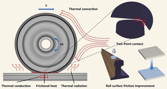
3]. Wheels are prone to two-point contact while sliding against the track. At this time, the friction creates frictional heat, the contact area rapidly heats up, plastic deformation in the material is accelerated, and the material softens. This results in a deterioration in wheel and rail profiles, affecting wheel and rail friction performance. Over time, high temperatures can cause various hazards to wheels and tracks, such as wear, fatigue, and cracks. Additionally, this increases the possibility of crack propagation during operation, affects the service life of wheels and rails, and endangers operational safety and ride comfort [
4]. Therefore, it is necessary to evaluate the thermal effect on rail materials caused by pure slip under two-point contact conditions.
Many scholars have carried out studies on temperature-rise estimation and the lubrication of friction surfaces, mainly via the use of numerical analysis, finite-element means, and quasi-static experimental simulations. Jaeger [
5] was the first to study the temperature-rise problem concerning sliding contact, describing the heating theory of friction surfaces. Gallardo et al. [
6] compared experimentally obtained data with temperatures using an analytical model and showed that the two frictional heats are equivalent and well correlated. Ertz and Knothe [
7] demonstrated that the long-term movement of wheels on tracks should be considered not only for thermal convection boundary conditions, but also for heat transfer from high-temperature wheels to low-temperature tracks. Wu et al. [
8] analyzed the thermoelastic deformation and residual stresses after wheel–rail sliding contact. The results showed that the frictional heat of wheel–rail contact has a significant effect on the residual deformation, plastic strain, and residual stress on the rail surface. Chen Shuai [
9] presented a model for predicting wheel wear in subway vehicles using the Archard wear model. The model considers the adhesion and slip zones, as well as the wear depth, and incorporates the temperature-dependent properties of the wheel material to investigate the effect of temperature on wheel wear. Fischer et al. [
10] considered thermal convection and radiation with the environment, temperature-dependent material thermal coefficient, and thermoelasticity to solve the thermoelastic wheel–rail frictional-contact problem. Yang et al. [
11] concluded that the maximum equivalent force and temperature of wheel–rail sliding friction are at the center of the subsurface contact patch and the rear half, respectively, and the rail frictional-heat-affected layer is very small at about 3 mm. Rao et al. [
12] used finite-element software to conduct an elastic–plastic analysis of wheel–rail sliding and proved that the ambient temperature could be taken as a fixed value in a numerical simulation and finite-element analysis. Wang et al. [
13] studied the effect of the presence or absence of convective-heat-transfer coefficients on the temperature and stress fields of wheel–rail contact patches and proved the great influence of convective-heat-transfer coefficients in the simulation process. Liu et al. [
14,
15] analyzed a two-dimensional bilinear elastoplastic finite-element model and, with the help of experiments, derived the effects of variable friction coefficients and rail stripping off blocks on wheel–rail frictional temperature and stress increases. Hou et al. [
16] conducted long-term tracking tests on actual operating lines and demonstrated that wheel pairs with a traverse of 10 mm or above would produce a contact between the wheel rim and rail gauge angle. Wang Ping [
17] presented a three-dimensional wheel–track thermodynamic-coupling model that takes into account longitudinal and transverse creep slip rates and spin. The model was applied to a small-radius curve section of a subway and used to compare the temperature field calculated by a general temperature-rise calculation model with the thermodynamic-coupling temperature-rise calculation model. Long et al. [
18] established a three-dimensional finite-element model for small-radius curves and analyzed the tendency for wheel rim and rail gauge angle extrusion to occur in small-radius curve sections, resulting in stress concentration and wear.
Valeriy Kosarchuk [
19] introduced a novel lubricating composition that reduces the wear resistance of rails and wheels, protects against electrochemical corrosion, and stabilizes the coefficient of friction at an optimal level. Tomeoka et al. [
20] evaluated several types of friction modifiers using friction tests and invented onboard equipment to precisely spray the friction modifier from the bogie to the rail top. Spiryagin et al. [
21] input experimental data into a model to obtain the corresponding numerical-temperature calculations for the correct selection of lubricant types. Gerald Trummer [
22] proposed a model that predicts how the coefficient of friction changes in railway operations when using top-of-rail products. Li et al. [
23] studied wheel–rail friction behavior under different operating conditions using wheel–rail contact simulation tests. The results showed that the top-of-rail friction modifier could adjust the friction coefficient to near 0.2 and reduce the friction coefficient to 0.1 using lubricating oil. Ben White [
24] proposed a test method to evaluate the effectiveness of top-of-rail friction management products using a twin-disc test rig to gather data on the “effective level of friction” and “retentivity”. This method can provide valuable insights into the performance of such products.
In the above research on wheel–rail sliding contact analysis, the thermal-coupling method uses indirect coupling. The model is mostly a simplified model and does not consider the complete thermal-boundary conditions. This will affect the accuracy of the analysis results, and the contact parts also remain on the tread and hub. There is a lack of descriptions of friction heat generation in wheel–rail two-point contact behavior. The research on wheel–rail friction lubrication is mainly aimed at improving wheel–rail wear and damage, and there is little research on the effect of lubrication on rail friction heat. To more reasonably analyze the wheel–rail frictional thermal effect under two-point contact, this study addresses the shortcomings of the existing research and establishes a thermal-coupling finite-element model of equal proportion wheel–rail sliding based on temperature-dependent material properties. This model considers thermal conduction, thermal convection, thermal radiation, and heat flux between rail end surfaces. The thermal response of wheel–rail sliding friction is studied by using the direct-coupling method, and the influence of different axle loads, relative sliding speeds, and lubrication effects on the temperature and stress fields of the contact interface are analyzed.
3. Finite-Element Model
With the help of ANSYS software, a thermal-coupling finite-element model of equal proportion wheel–rail sliding is established in this paper, using an LM tread wheel and a 60 kg/m steel rail as examples. The direct-coupling method is used to analyze thermal–mechanical coupling of a wheel–rail under sliding contact. The temperature-dependent material properties and thermal-boundary conditions in the unsteady conduction process of friction heat are considered in this model. The wheels are LM wear treads with a diameter of 920 mm, the rail type is 60 kg/m, and the wheel–rail material parameters are modeled as temperature-dependent parameters, as seen in
Table 1 [
25].
The load transfer from the wheel to the track produces an elliptical contact area. The contact area includes the adhesion area and slip area, and the adhesion area is formed at the front of the contact ellipse, while the slip area is formed at the end [
26]. Once the traction force reaches its saturation value, the whole contact area changes to a pure sliding state, producing sliding between wheels and rails, as shown in
Figure 2. At this time, it is easy to produce a large-wheel-pair traverse, resulting in contact between the wheel rim and rail gauge angle. At the same time, wheel hub is contacting rail tread. As shown in
Figure 3, two connected friction contact pairs are established on a workbench, the dry-state conditions of the two contact pairs’ friction coefficient are taken as 0.4, and lubrication schemes are developed for the rail top friction adjustment, rail side lubrication, and both together. To model the lubrication layer, the surface-coating feature of ANSYS Workbench was used. The software provided a mechanical lubricating oil as the coating material with a density of 8.89 × 10
−7 kg/mm
3, a thermal conductivity of 0.000145 W/mm·°C, a specific heat of 1.845 × 10
6 mJ/kg·°C, and a viscosity of 1.06 × 10
−6 MPa·s. The optimal coefficient of friction and coating thickness for the lubrication layer were selected based on the position of the friction pair and recommendations given in reference [
23], resulting in a coating thickness of 0.1 mm. The friction coefficient is 0.2 when the friction modifier is applied on the rail top and 0.1 when the lubricant is applied on the rail side. The friction behavior is set to be symmetrical, and the equation uses the generalized Lagrangian method to update the stiffness at each iteration and define the heat-transfer effect on the contact surface.
Different mesh accuracies are set along different depths of the rail contact interface, as shown in
Figure 4. The mesh is refined in the contact area, the mesh size is encrypted to a minimum of 0.5 mm, and a coarse mesh is used for the other parts. The finite-element model has 298,178 nodes and 241,761 cells. In the coupled-field-transient model, the ambient temperature is set to 25℃, the thermal-convection coefficient is set to 12 W/(m
2·K), and the thermal-radiation emissivity is 0.95 for the wheel–rail frictional heat-generating surface [
27]. The vertical displacement of the bottom surface of the rail, the longitudinal and transverse displacement of the rail end surface on the near-wheel side, and the transverse displacement of the far-wheel end are constrained. The heat flux transmitted outward is set at both end faces, simulating the internal heat flow of the rail. Operating conditions are set for wheel sliding speeds of 1 m/s and 2 m/s and train axle weights of 20 t and 30 t. The axle loads are applied as vertical bearing loads on the axle center. Under different axle weight conditions, a single wheel supports bearing loads of 10 t and 15 t. The contact model is generally within the linear elastic range, where the mechanical properties and material properties are in accordance with linear elasticity. However, the effect of temperature on materials is nonlinear. The finite-element method is used to solve the influence of temperature on the contact characteristics of the friction surface. The model establishment and calculation are accomplished by using finite-element software.
4. Analysis of the Calculation Results
Dry wheel–rail contact with a sliding speed of 2 m/s and an axle load of 30 t is set as the standard operating condition.
Figure 5 shows the friction-temperature patch of the two contact points under the standard operating condition when sliding 200 mm. The center temperature of the contact patch on the rail top is 813 °C, and the center temperature of the contact patch on the rail side is 547.7 °C. The frictional temperature rise on the rail side is 67% of that on the rail top, and the temperature dissipates faster. As shown in
Figure 6, the shape of the contact area basically agrees with the Hertz contact theory model, with a skewed peak-shaped temperature field. The high-temperature points are located in the rear half of the contact area. Due to the cooling effect of the rail material that first contacts the wheel on the friction heat, the temperature rises instantaneously and then contacts the rear half of the contact area. A good correlation was found between the analytical results and the experimental data in the literature [
6,
28].
4.1. Analysis of Temperature Rise
To analyze the factors influencing rail-temperature rise under pure-sliding conditions, we created four operating conditions and defined the contact area of the rail top surface as α and the contact area of the rail side as β, as shown in
Table 2.
Figure 7 shows the variation curves of the contact-patch temperature rise with slip distance. The temperature-rise trend presented is in agreement with the existing dry-state sliding-friction flash-temperature model, and the contact-spot temperature prediction has an asymptotic relationship with the results of the flash-temperature calculation [
29,
30,
31]. The highest temperatures of α and β under operating condition 1 are 904.9 °C and 554.6 °C; the highest temperatures of α and β under operating condition 2 are 619.3 °C and 467.1 °C; the highest temperatures of α and β under operating condition 3 are 685.9 °C and 363.8 °C; and the highest temperatures of α and β under operating condition 4 are 497.8 °C and 334.5 °C. The highest temperature of the contact patch on the rail side under different operating conditions is 55–75% of the highest temperature of the contact patch on the rail top. The differential value between the two is 152.2 °C for operating condition 2 and 163.3 °C for operating condition 4. This means that the maximum temperatures of the two contact patches at a low sliding speed are similar. The rail top temperature tends to be stable and fluctuates in a small range after sliding 50 mm, and the curve spacing is larger at different speeds with the same axle load. This indicates that the sliding speed has more influence on the friction-temperature rise at the rail top. The temperature on the rail side regularly rises with the sliding distance. In
Figure 7b, the positions of curves 2 and 3 are exchanged, which shows that the axle load has a greater influence on the friction-temperature rise on the rail side.
4.2. Stress Analysis
In order to study the stress state of the two contact areas of the rail, the friction and contact stress of the contact side were analyzed for the above four operating conditions. From
Figure 8, it can be seen that the contact- and friction-stress values on the rail side are 76–96% of those at the rail top. The mechanical response of the top and side of the rail under the same operating conditions is consistent. The maximum contact stress differential value between α and β areas is 134.7 MPa under operating condition 1. The differential value of contact stress is 65.8 MPa under operating condition 3. The differential value is 10–30 MPa under operating conditions 2 and 4. The differential value of friction stress has the same trend, which means that the stress state of the rail top and side is similar when the sliding speed is low.
An in-depth analysis of the stress effects on the contact interface under different operating conditions indicates that the frictional-stress values at the rail top are 258.6 MPa, 186.2 MPa, 168.9 MPa, and 130.2 MPa, and the contact-stress values at the rail top are 646.4 MPa, 465.4 MPa, 422.5 MPa, and 325.5 MPa. The contact- and friction-stress values at α under operating condition 2 are very similar to those under operating condition 3. The lines in
Figure 8 are approximately horizontal, indicating that a change in sliding speed of 1 m/s and a change in axle weight of 10 t have nearly the same effect on the contact mechanics of the rail top under standard conditions. The effect of the axle weight is slightly greater than that of sliding speed.
The friction-stress values at the rail side under the four conditions are 204.7 MPa, 175.5 MPa, 142.7 MPa, and 125.9 MPa. The contact-stress values are 511.7 MPa, 438.7 MPa, 356.7 MPa, and 314.6 MPa. The differential value of friction stress at the rail side with the same axle weight and different speeds is within 30 MPa. The differentials are more than 50 MPa for different axle weights at the same speed. The differential value of contact stress on the rail side with the same axle weight and different speeds is between 40 and 70 MPa. The differentials between the same speed and different axle weights are more than 120 MPa. This indicates that axle weight plays a major role in influencing the two types of rail side stresses analyzed, while the effect of speed is very limited.
4.3. Lubrication Improvement
The frictional-heating and contact-stress values for the rail gauge angle account for more than 60% of the rail top. Additionally, the rail gauge angle structure is more fragile and does not have a good force relationship [
32]. Long-term neglect of frictional heating at the gauge angle can lead to material softening, derailment, and other major traffic safety accidents. On train lines with heavy axle loads, snaking movements, acceleration and deceleration sections, and small-radius curves, rail-cooling devices and corresponding lubrication works should be installed. This can help to avoid and improve thermal rail damage caused by wheel transverse displacement and wheel–rail sliding friction. This paper analyzes the cooling effect and stress improvement under three lubrication coating schemes and guides the corresponding maintenance work. Condition 1 is set as a dry condition as the control. The effect of the lubrication state on wheel–rail thermal–mechanical coupling is shown in
Figure 9.
The rail top solid friction modifier reduces the temperature at α by 428.9 °C but increases the temperature at β by 42.3 °C. The rail side solid friction modifier significantly reduces the temperature at β but increases the temperature at α by 236.6 °C. The temperature at α is as high as 904.9 °C under the original dry condition and reaches 1141.5 °C after applying the rail side lubricant. This indicates that the application of a friction agent to a single-contact area leads to a significant reduction in frictional heat in the contact pair, but raises the temperature of the other contact pair. This side effect can be avoided with overall lubrication, and a good improvement can be achieved for both contact areas. The improvement rates are 47.1% and 70.3%, as shown in
Figure 10.
The contact stresses of both friction pairs are reduced under both rail top friction and overall lubrication schemes. The improvement rate ranges from 9 to 14%, as shown in
Figure 11. The effect of coating the rail top friction modifier alone is better than that of co-lubrication. In contrast, coating the rail side lubricant leads to a simultaneous deterioration in the contact-stress state at both contact interfaces.
All three lubrication schemes contribute to an improvement in friction stresses. As shown in
Figure 12, the rail top solid friction modifier reduces the friction stress at α by 56.9% and at β by 13.6%.
The friction stress at β is reduced by 74.5%, and the friction stress at α is increased by 2.2%, when the rail side contact area is lubricated. The friction stresses in the two areas are reduced by 56.2% and 77.4% when the rail top and rail side are lubricated simultaneously. The above conclusions can guide maintenance and repair personnel in the placement of rail wear lubrication treatments. It is worth noting that lubricating only the rail gauge corner will lead to increases in the rail top contact area temperature and contact stress. The best choice is overall friction improvement if one considers the economic benefits and coating difficulty.
5. Conclusions
A thermal-coupling model was used to investigate the temperature and stress response of wheel–rail sliding friction under two-point contact conditions. Based on the calculation results of this paper, the following conclusions can be obtained:
- (1)
The temperature on the rail side is 55–75% of that of the temperature at the rail top. The highest temperature values are found in the rear half of the contact patch. The lower the sliding speed, the closer the temperature rise of the two contact patches. Sliding speed accounted for a relatively large impact on the rail top friction temperature rise. The axle weight has a more obvious effect on the rail side friction temperature rise.
- (2)
The contact- and friction-stress values on the rail side are 76–96% of those at the rail top. The mechanical response of the top and side of the rail under the same operating conditions is approximate. The sliding speed is lower, and the stresses at the two contact interfaces are similar. The axle weight plays a major role in influencing the stress on the rail side, while the effect of sliding speed is very limited.
- (3)
Lubrication in the single-contact area greatly reduces the thermal response of the contact pair. The friction heat and friction stress are improved by 47.4% and 56.9% when the rail top friction is adjusted, and the improvement is 72.5% and 74.5% when the rail side is lubricated. However, this coating scheme will increase the friction temperature of the other contact pair. The optimal coating scheme of rail lubrication is overall lubrication, followed by the rail top solid friction modifier. It should be noted that only coating the rail side with lubricant will cause the stress state of the two contact interfaces to deteriorate at the same time.
- (4)
The model established in this paper can calculate the friction-temperature rise and contact-interface stress of a train under two-point contact and guide the lubrication maintenance of rails.
This model can be further improved by adding the complete track geometry and combining the ambient humiture and temperature in subsequent studies. The complete track geometry can be incorporated into the finite-element model, along with environmental parameters, such as temperature and humidity, to improve the model’s accuracy. Point-cloud data can be obtained using laser scanning or unmanned aerial vehicles to generate a digital-terrain model of the track. The necessary geometric parameters, such as lateral and longitudinal height changes, curvature radius, curvature-change rate, etc., can then be extracted from this model. The extracted data can be processed using interpolation or conversion methods to obtain mesh data appropriate for a finite-element model.
For the measurement of environmental parameters, proper instruments and spatial distribution, such as network thermometer hygrometers or meteorological stations, should be selected to avoid external interruption. The acquired data should be further processed and analyzed through statistical analysis, interpolation, or filtering to acquire suitable data for use in a finite-element model. The resultant environmental data can then be incorporated into the finite-element model and combined with the track and vehicle models for a multiphysics finite-element analysis. This usage can examine how temperature and humidity influence train-frictional performance and wheel–rail contacts.
In the future, a more comprehensive approach to wheel–rail-friction analysis can be developed for specific railway lines under realistic conditions.


