Article

Investigation of the Hardness Development of Molybdenum Coatings under Thermal and Tribological Loading

1
Institute of Forming Technology and Machines, Leibniz Universität Hannover, 30823 Garbsen, Germany
2
Institute for Machine Design and Tribology, Leibniz Universität Hannover, An der Universität 1, 30823 Garbsen, Germany
*
Author to whom correspondence should be addressed.
Lubricants 2023, 11(7), 283; https://doi.org/10.3390/lubricants11070283
Submission received: 26 May 2023 / Revised: 22 June 2023 / Accepted: 28 June 2023 / Published: 30 June 2023
(This article belongs to the Special Issue Multiscale Tribology of Solid Lubricants)

Abstract

:
The increasing global demand for innovative and environmentally friendly lubricants can be met through the use of solid lubricants. By switching from conventional lubricants such as various oils or grease to solid lubricants, new scopes of application can also be opened up. The main requirements for solid lubricants are a reduction in the coefficient of friction (CoF) and an increase in wear resistance. Due to the favourable material properties, molybdenum (Mo) coatings fulfil the tribological requirements and are therefore promising solid lubricants which can be applied via physical vapour deposition (PVD). In this work, the impact of substrate temperature on the hot hardness of deposited Mo coatings was determined. The specimen with the highest hot hardness was then tribologically examined both at the micro and nano level. Through an analysis of the wear tracks by means of nanoindentation and scanning electron microscopy (SEM), it was possible to detect the influence of the tribological load separately from that of the thermal loads. The results showed that the tribological load influenced the Mo coating by significantly increasing its hardness. This was achieved due to the work hardening of the Mo layer leading to an increase in the wear resistance of the coating.

1. Introduction

The trend of the use of oils and greases as lubricants is gradually being curtailed due to their negative contribution to environmental pollution. Solid lubricants can serve as a potential substitute in terms of the efficient use of resources because they can be applied in a targeted manner in tribological contact [1]. Moreover, solid lubricants can also open up new fields of application in which conventional lubrication systems are prohibited, such as the food industry or aerospace industry. A solid lubricant that is particularly suitable for dry lubrication is molybdenum disulphide (MoS2). Due to the special structure of MoS2, low frictional torques occur, e.g., in rolling contact, as the plate-like layer structure allows sliding [1]. The lubrication mechanism of MoS2 has been intensively investigated and comprehensively described, as the review article by Vazirisereshk et al. demonstrates [1]. Nevertheless, MoS2 is still a major field of research in current research. For example, Gokce et al. investigated the influence of surface roughness on the wear behaviour of MoS2-coated rolling contact bearings. The optimum in the investigations was between Ra 0.15 and Ra 0.3 μm [2]. The use of MoS2 as dry lubrication in highly loaded gear applications was investigated in [3]. However, other environmental conditions prevail in space, which have been investigated by Yaqub et al. in terms of tribological performance [4]. MoS2 is not only used as a coating in tribological contact but also specifically in material alloys to improve dry sliding properties. Ragupathy et al. used MoS2 in an aluminium alloy and were able to significantly reduce the dry sliding properties [5]. The use of MoS2 as a nanoparticle is a new field of research in which individual flakes or layers of MoS2 are used in tribological contact, similarly to the case with graphene [6,7].
Research is currently being conducted on a new solid lubricant based on pure molybdenum (Mo). Pure Mo was used by Idir et al. and applied via thermal spraying. In wear tests, they were able to achieve an improvement in wear protection due to high hardness. In addition, the tribological properties were improved [8]. However, many pores and oxides are formed in thermally sprayed coatings, so there are not necessarily pure Mo-coatings, but much more Mo oxides, which nevertheless have very good tribological properties. Mo coatings can also be produced via physical vapour deposition (PVD), where the oxygen supply can be controlled very well. The current research project investigates the use of Mo-based solid lubricants for rolling bearings. Therefore, Mo-layer systems were produced by means of physical vapour deposition (PVD), in which the solid lubricant molybdenum trioxide (MoO3) was generated from a Mo layer via tribo-oxidation [9]. In addition, various coating systems have been developed with a MoO3 top layer, so that MoO3 is directly available in the run-in phase. The MoO3 top layer was created via reactive deposition with a Mo target on the one hand and with a MoO3 target on the other. While MoO3 takes over the lubricating effect, the Mo reservoir ensures a continuous lubricant supply through tribo-oxidation. The layer system consisted of a 2 µm thick Mo reservoir and a 500 nm thick MoO3 top layer [10]. The mechanical characterisation of the thin layers was carried out via nanoindentation. This showed that MoO3, due to its low hardness compared to that of the harder Mo reservoir, is distributed particularly quickly with a lubricating effect in tribological contact. Wear characterisation on the micro-level is not possible for the thin and quickly worn MoO3. Therefore, the wear behaviour of the Mo and the MoO3 layers were characterised and modelled via nano wear testing [11]. For the use of the nano wear model in, e.g., microstructure simulations or the finite element method, scaling to the micro-level must be fulfilled. A transfer from the nano- to the micro-level first requires an analysis of whether or not the wear tests on both levels show similar wear mechanisms. Furthermore, the nano wear model can be extended if the hot hardness of the Mo layer is known.
One way to influence the mechanical properties of the Mo coating system is to vary the sputtering parameters, such as the sputtering temperature, the process pressure or the inert gas used. Deambrosis et al., investigated the influence of different inert gases at varying process pressures on the mechanical and morphological properties during the sputtering of Mo coatings. It was shown that a porous layer was formed with xenon, whereas no pores could be detected when using argon. With regard to the sputtering pressure, it was found that the hardness and elastic modulus values decrease with increasing pressure [12]. Bolef et al., and Farraro et al., for example, investigated the development of the mechanical properties of Mo at elevated temperatures, such as the modulus of elasticity, which decreased linearly with an increasing temperature [13,14]. The determination of the hot hardness of Mo was performed by Pisarenko et al., in an argon and helium atmosphere. In addition, Pisarenko et al., investigated the effect of annealing and work hardening Mo on hot hardness. Differences in the hot hardness between both conditions up to 1200 °C were found, in which the hot hardness of the work-hardened Mo was higher than that of the annealed Mo. From 1200 °C onwards, the hardness values were equal, since the residual stress of work hardening was relieved by the temperature increase [15]. Nanotechnological characterisation at elevated temperatures is demanding and poses new problems. The problems were eliminated with the newly developed measuring chamber for nanoindentation tests at temperatures of up to 1100 °C by Minnert et al. The measurements could be repeated without large scattering. For validation, a Mo single crystal was investigated [16]. Characterisation of nanohardness at room temperature of Mo and MoO3 was carried out by Heimes et al. [17]. Walia et al. examined the change in electromechanical properties in MoO3 and MoS2 via nanoindentation [18]. Tribological investigations on Mo and MoO3 were carried out on the micro-level by Konopka et al., via sliding tests [19]. Experiments in the FE8 test rig with a coating system of Mo and MoO3 were carried out by Konopka et al. The axial bearing washers were coated and the cylindrical rollers were uncoated. In the tests, running times of up to 3000 min could be achieved without a bearing failure or the Mo coating being used up. In comparison, the uncoated reference only managed up to 40 min. After the tests, the uncoated cylindrical rollers had a transfer layer of Mo oxides, which was produced via transfer lubrication [20].
Based on the investigations of Konopka et al. [20], the objectives of this work were to determine the influence of the sputter temperature on the hot hardness of the molybdenum layers and to investigate why the molybdenum layers were not completely consumed in the bearing test. For this purpose, Mo layers were deposited on hardened rolling bearing steel AISI 52,100 using PVD technology, whereby the substrate temperature was varied. The influence of the sputter temperature on the hot hardness of the Mo layer was investigated via nanoindentation. Tribological investigations on the micro and nano level should help to understand why Mo coatings are so wear resistant. To support this, the wear areas were analysed via SEM. The following questions should be answered by the investigations:
  • How does the sputtering temperature affect the hot hardness of the Mo coating?
  • Why is pure molybdenum so wear-resistant and what mechanisms are responsible for this?
  • Are the wear mechanisms different at the nano and micro level and how can this be used for the wear modelling of molybdenum coatings?

2. Materials and Methods

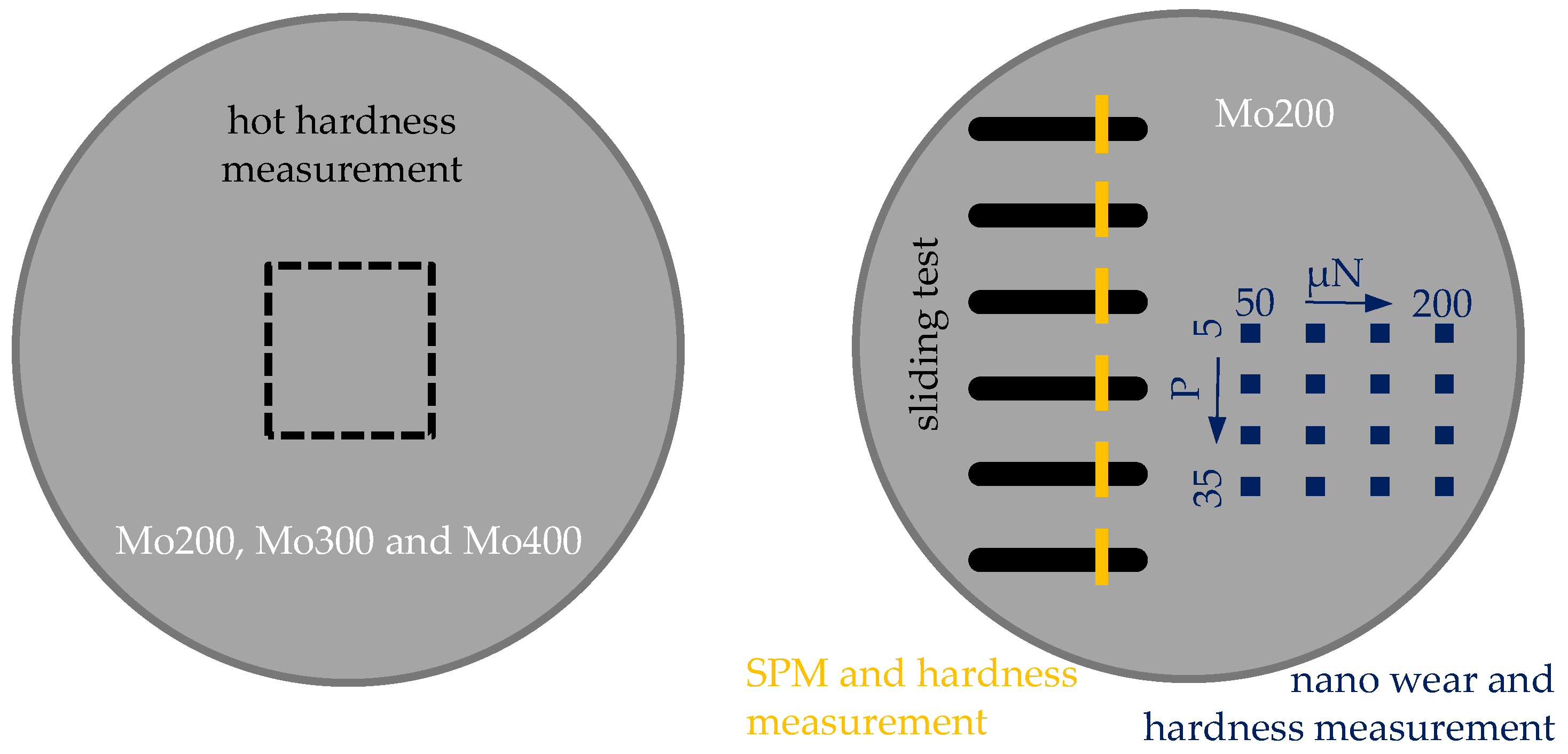
2.1. Manufacture of the Specimens

As mentioned in the introduction, the Mo coatings were deposited via PVD. Before the sputtering process, the cylindrical substrate specimens with a diameter of 14 mm and height of 5 mm were ground plane-parallel and mirror-polished on one side. The substrate consisted of hardened AISI 52,100 roller bearing steel and was cleaned in an ultrasonic bath for 15 min with acetone and isopropanol before being put into the PVD recipient. The deposition of the Mo coatings was carried out under vacuum, at a pressure of 6 × 10⁻⁷ mbar in the recipient. After reaching the vacuum pressure, the polished substrate surfaces were cleaned via plasma etching for 5 min. Afterwards, the recipient was filled with argon at a flow rate of 50 sccm and the substrate was heated to the respective sputtering temperature. Table 1 lists the sputtering parameters for the specimens investigated. The parameters were kept constant except for the substrate temperature. A Mo target with a purity of 99.95% was used, whereby the process’ partial pressure of argon was constantly set to 2.2 × 10⁻² mbar during the deposition of the coating, following Deambrosis et al.’s work in which the highest layer hardness was achieved at this pressure with no detection of pores [12]. Based on experience from previous investigations and the known deposition rates, a layer thickness of 2 µm was aimed for, as this achieved the best layer adhesion [9,10,19]. In addition, silicon wafers were added to the process. These were broken and the fracture surface was examined using SEM. No pores or defects were found in the fracture surface. The layer thicknesses of 2 µm could be confirmed. The morphology of the sputtered Mo layer was homogeneous and varies in terms of the crystallite size produced between 50 nm and 170 nm. The crystallites were characterised by a stalk-like growth perpendicular to the substrate surface. Five specimens were coated with each production batch. In each case, one specimen was used for the hot hardness measurement and the remaining four specimens were used for the tribological tests and nanotechnological investigations. This ensured that the results of the tribological and nanotechnological tests were not influenced by the thermal loading during the hot hardness measurements.

2.2. Tribological Investigation

For the tribological investigations on the micro level, MILLI TRIBOtester PREMIUM (TRIBOtechnic, Ile-de-France, IdF, FR, Clichy, France) was used. Here, investigations were carried out using the sliding test setup (ball-on-disc). In preliminary tests, hardened steel balls were used in the sliding test on the deposited Mo layer. The steel balls were always worn so that no wear of the Mo layer could be detected. Therefore, a ceramic ball made of Si3N4, with a radius of 3 mm was placed on the coated specimen with a defined normal force of 25 mN. With an oscillating movement at a constant sliding speed of 5 mm/s and an oscillating track of 2.5 mm, the tests were carried out with the cumulative total sliding distances listed in Table 2. In order to assess the tribological behaviour of the Mo coating, reference measurements were also carried out on uncoated specimens; see S01 in Table 2. Experiments were conducted under laboratory conditions with an average ambient temperature of 22.3 °C and an average ambient humidity of 14.4%.
F R = μ   F N
The tangential forces, F R , are measured continuously during sliding. This allows the development of the coefficient of friction (CoF), μ, over the duration of the test to be calculated via the applied normal force, F N , using Coulomb’s law of friction; see Equation (1). All six parameter combinations were each performed on four individual specimens.

2.3. Nanotechnical Investigations

In order to assess the coating hardness at the enhanced temperatures, the specimens were tested on Hysitron TriboIndenter® TI 950 (Bruker, Minneapolis, MN, USA). Therefore, the xSol 800 heating module was used, which allows hardness measurements in an inert gas atmosphere at temperatures up to 800 °C. Figure 1a shows the heating module, consisting of an upper and a lower heater, which could each be adjusted separately with a respective temperature measurement. To prevent the housing of the upper and lower heater from heating up completely to the test temperatures, the housings were each cooled via the cooling channels. The specimen was placed on the lower heater. The upper heater was then passed over the columns and lowered until it was in contact with the specimen surface. This allowed the specimen to be heated evenly from below and above via heat conduction. Such a design results in a specimen height-dependent distance between the upper and lower heaters, which means that a standard seal cannot guarantee that the measuring chamber is sealed off from oxygen. Therefore, TFC silicone rubber type 4 kneading silicone (Troll Factory, Riede, Germany) was used for the measurements of each specimen. The silicone rubber was placed between the heaters, so that the measuring chamber could be sealed after the upper heater was put on and cured. Before each testing program, the measuring chamber was flooded with nitrogen at a pressure of 2.5 bar for 5 min. This forced the air out of the measurement port in the upper heating plate, and continuous rinsing with nitrogen ensured that the measurements could be taken in an inert gas atmosphere. Subsequently, the nitrogen pressure was reduced to 1.2 bar, as otherwise the gas flow would have influenced the measurements. A triangular Berkovich diamond tip with a tip radius of less than 50 nm was used to record the hot hardness. Calibration of the area function of the tip was performed on a fused quartz specimen using the method of Oliver and Pharr [21]. The heating profile for the measurements is plotted in Figure 1b. Here, each temperature was kept constant for 75 min and then increased within 25 min. The measurements began after the test temperature in the upper and lower heater was constant for 15 min. To avoid dynamic measurement errors, among other things, a trapezoidal force–displacement function was used [22,23]. For each test temperature, 25 indents with a distance of 6 µm and a normal force of 5000 µN were recorded.
Furthermore, nano wear tests were carried out at room temperature. The nano wear tests were performed with a cube coner indenter made of diamond in order to subsequently examine the wear fields for a possible change in hardness. Here, the same normal forces and repetitions as those in [11] were used: 5–35 passes (P) and 50–200 µN. The wear fields with a size of 8 µm × 8 µm were positioned and inserted with a distance of 50 µm. A Berkovich diamond indenter was then installed to investigate the change in hardness caused by the nano wear tests. The tip was calibrated on a fused quartz specimen. Subsequently, the wear fields were detected via in situ scanning probe microscopy (SPM) and the indenter was positioned centrally over the wear field. Over the wear field and the unworn surrounding areas, 7 × 7 indents were placed in a square pattern with a spacing of 3 µm. A normal force of 5000 µN was applied to all indents. By linking the hardness values with the recording position, it was possible to record the hardness in and around the worn area. The sliding tracks, which were generated on the milli-tribometer, were also examined for a possible change in hardness due to the tribological load. For this purpose, SPM and hardness mappings were carried out with a Berkovich indenter over the sliding tracks, as schematically shown in Figure 2.
Since the sliding tracks were too wide to be recorded with a single SPM scan, a combination of several scans was used. First, a square pattern of 5 × 5 indents with a spacing of 4 µm was induced. Then, the measuring spot was scanned in an area of 40 µm × 40 µm by means of SPM. Afterwards, 20 µm was moved vertically in the y direction, and the pattern of 5 × 5 indents was induced there again. By scanning 40 µm × 40 µm again, the previous indents were also recorded in addition to the newly introduced indents. This allowed the individual SPM scans to be joined together and aligned with the overlapping indents. Each sliding track thus underwent six individual SPM scans. Using Gwyddion® (version 2.56, open-source software), the individual SPM scans were combined and the wear depth was determined via line scans. In addition, the development of the hardness values over the sliding track was considered. The nano wear tests and the characterisation of the change in hardness within the sliding track as well as the nano wear fields were carried out on a single specimen.

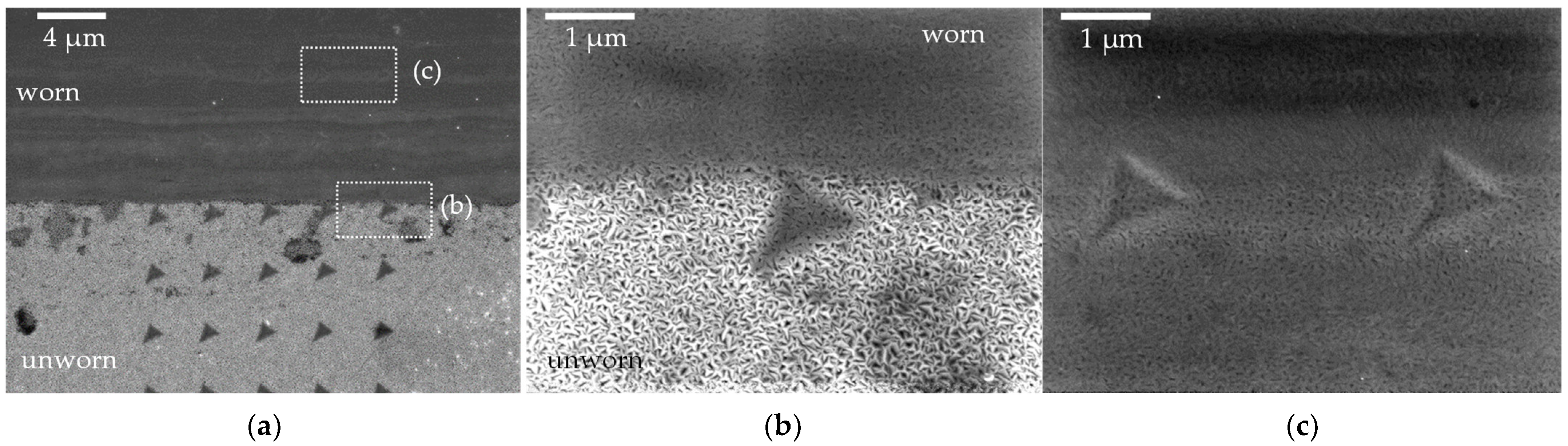
2.4. SEM and Optical Investigations

The sliding tracks and the nano wear fields were investigated using SEM with energy-dispersive X-ray measurements (EDX) with Supra 40VP (Zeiss, Oberkochen, Germany) in order to understand the mechanisms of hardness development caused by tribological loading. Therefore, the focus was on the examination of the introduced indents and the correlation of the hardness values with the images taken by means of the Inlens detector. Furthermore, the sliding tracks and the nano wear fields were analysed with the use of EDX mappings, so a possible enrichment of the wear tracks with oxygen due to the tribological load could be verified. In addition, the sliding tracks were recorded using the light microscopic optics of Hysitron TriboIndenter® TI 950 in order to implement a coupling between the hardness values and the sliding track size.

3. Results and Discussions

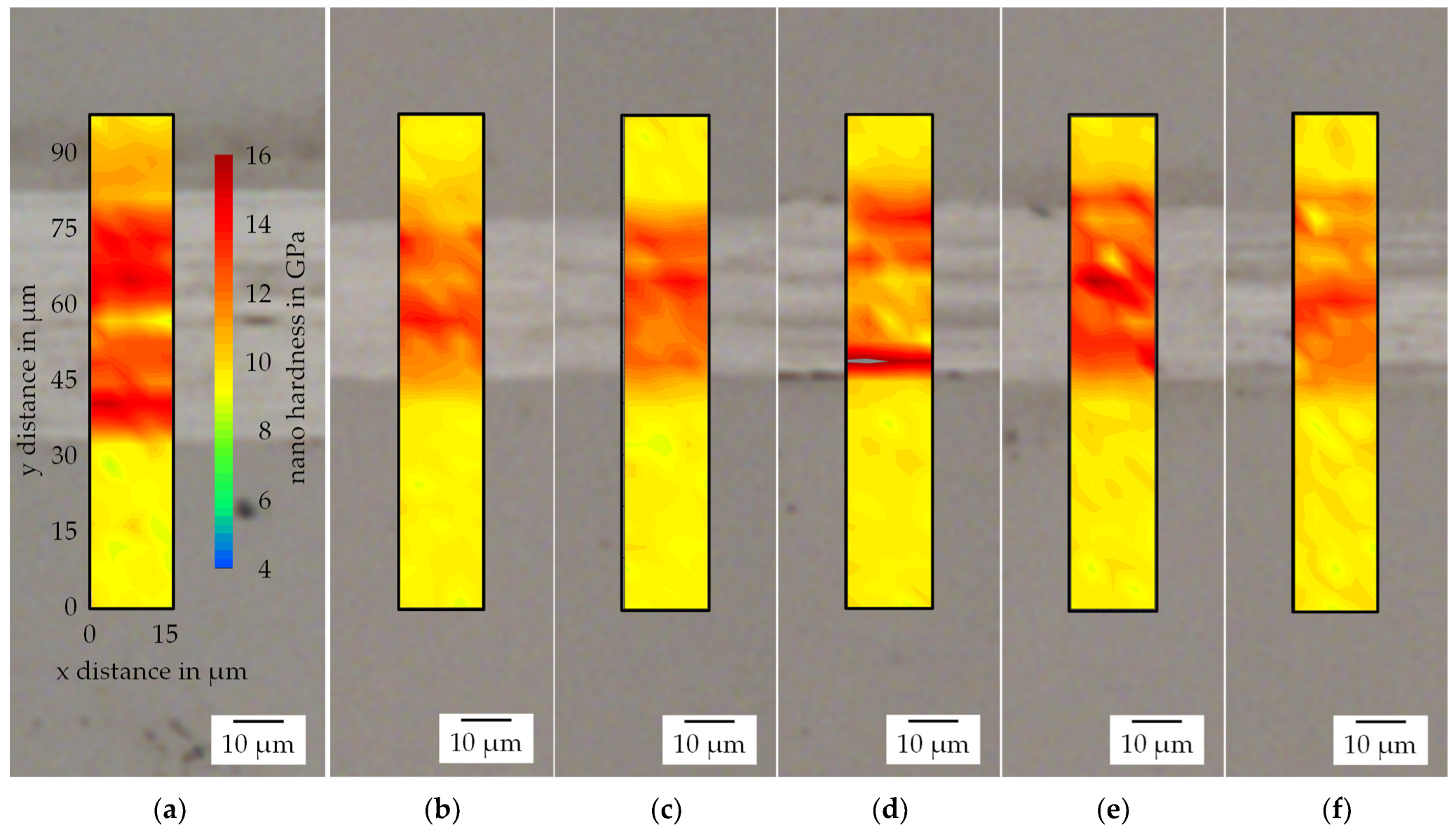
3.1. Nanotechnical Investigations
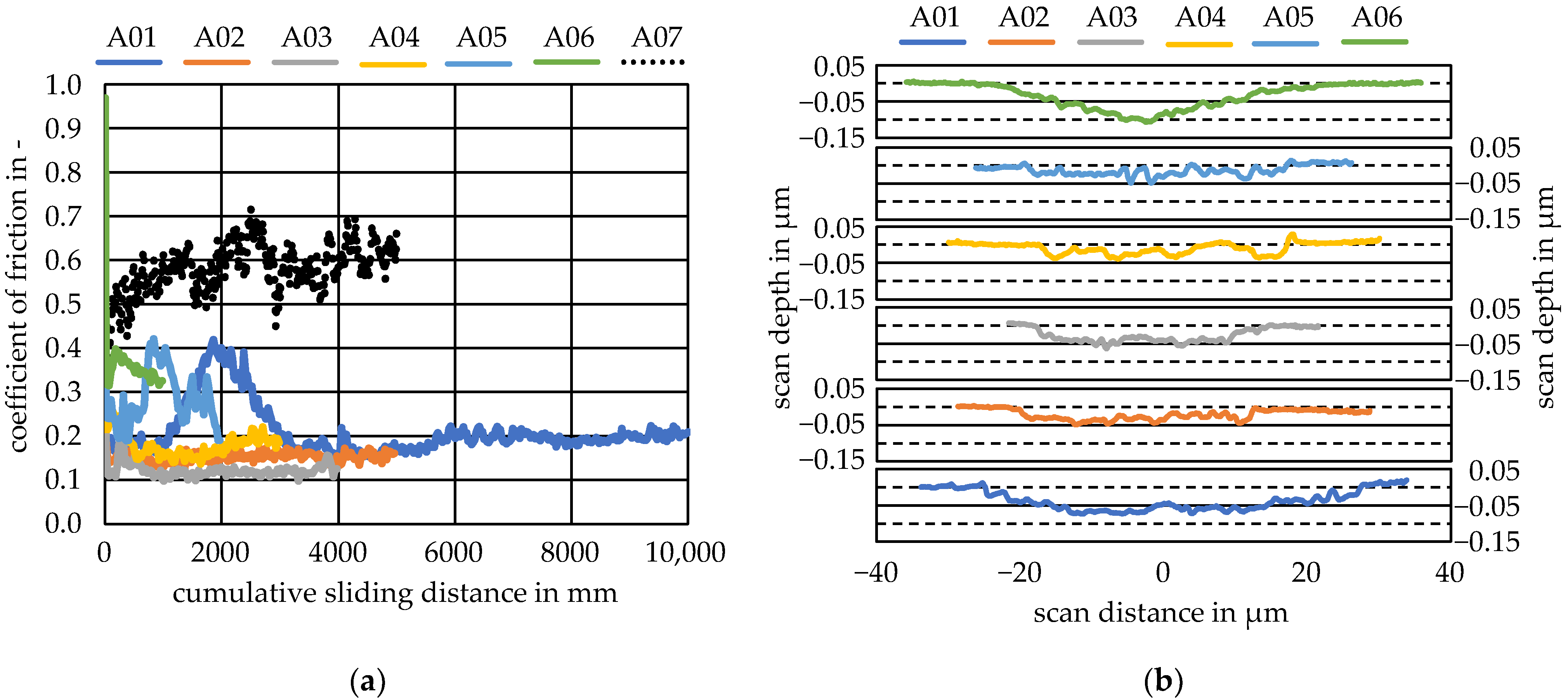
To determine the influence of different sputtering temperatures on the hot hardness of the Mo coating, the specimens were investigated in the temperature range of 20–400 °C. Such a temperature range covers possible peak temperatures in tribological contact during solid lubrication, so that the coatings produced can be evaluated and selected with regard to subsequent application. The development of the hot hardness for the Mo coatings is plotted in Figure 3a. All coatings initially showed similar behaviour between 20 °C and 200 °C. The hardness dropped steeply with an increase in temperature. Between 200 °C and 400 °C, the hardness for Mo200 remained almost constant with a slight decrease, while for that of Mo300, which continued to drop slightly at 300 °C, increased again slightly at 400 °C. For Mo400, the hardness increased slightly at 300 °C and dropred significantly below the hardness values for Mo200 and Mo300 at 400 °C. The standard deviations show a small scatter for all measurements. The development of the penetration depth for Mo200, Mo300 and Mo400 is plotted in Figure 4b. With an increasing temperature, the penetration depth was reciprocal to the hardness development in Figure 4a. The greatest penetration depth was at 400 °C for sample Mo400 with an average of 157 nm, which means that the 10% rule was met.
No clear influence of the sputtering temperature could be determined with the specimens investigated here, since the results of Mo400 range mostly between Mo200 and Mo300. The specimen Mo200 had the highest hot hardness with the investigated temperatures, which indicates that this variant has the highest resistance to abrasive wear. However, other factors such as the elastic and plastic behaviour of the coating as well as the adhesion tendency also contribute to wear resistance. These factors could not be investigated in the temperature range from 20 °C to 400 °C within the scope of this work. Therefore, the measured hot hardness was used to select the coating. Therefore, the coating at a sputtering temperature of 200 °C was selected for further investigations.

3.2. Sliding Tests

The development of the CoF over the cumulative sliding distance is plotted in Figure 4a. The CoFs of tests A01–A04 were constant between µ = 0.1–0.2. It is noticeable that in experiments A01 and A05, the CoF initially rose to about µ = 0.4 and then fell again, whereas in A06 the CoF started very high with µ = 0.95 and then fell to the level of that in A01 and A05 after a few cycles. One reason for the higher CoF could be, for example, that smaller particles came into contact between the sample and the ball. These particles could have then led to a groove that penetrated deeper into the coating, which would have increased the tangential force and thus the CoF. For solid lubrication, it is typical that at the same tribological load as the normal force and the sliding speed, there is a greater dispersion or spontaneous events in the course of the CoF [20]. Deeper penetration in combination with a high CoF can be observed for example in Figure 4a,b. The wear depth measurements in Figure 4b were taken after reaching the respective maximum sliding distance of the sliding test. A06 shows one of the largest wear depths, although the sliding distance was the smallest, but the CoF increased to µ = 0.95 in the first sliding segment. Presumably, the wear depth was already reached there, as the CoF then dropped to µ = 0.3–0.4. The wear depths of the sliding tracks were relatively similar and showed no increase with an increasing sliding distance. In the case of A01, however, it could be seen that the wear track was significantly wider than of the others. The development of the CoF of the reference measurement S01 shows an increase in the CoF from µ = 0.45 to approx. µ = 0.6 towards the end of the test. At a depth of 0.1 µm and a wear mark width of 35 µm, the wear mark of S01 was significantly more pronounced than that of the coated specimens; see Figure 4b. Finally, with the use of the wear depth, as well as the development of the friction coefficients, it can be concluded that the Mo layer was only slightly worn and that the solid lubricant fulfilled its purpose. Furthermore, the sliding paths investigated here appeared to exhibit initial wear, which did not continue with the increasing sliding distance. The reason for this could be the work hardening of the layer due to the tribological load, which was further investigated by examining the hardness.

3.3. Wear Track Analysis

To analyse the sliding tracks, optical images, shown in Figure 5, were taken and are presented together with an overlay of the hardness maps. The hardness measurements were carried out analogously to the wear depth measurements in Figure 4b after reaching the respective maximum sliding distance of the sliding test. The worn areas were coloured lighter than the unworn ones. Within the sliding tracks, there were also partial areas that showed a similar grey tone to that of the unworn areas, as can be seen in Figure 5a,c,d,f. It can also be seen, that all the sliding tracks, with the exception of A01 in Figure 5a, featured approximately the same width. The wider sliding track of A01 coincides with the line scan from Figure 4b. The overlay of the hardness maps shows an increase in hardness within the sliding track for all of the cases. The unworn layer was characterised by a hardness of approx. 9.8 GPa, while in the wear track the hardness increased to an average of 14.0 GPa. A strong increase in hardness with an increasing sliding distance cannot be determined. Within the wear marks, there were some areas that experienced slight to no increases in hardness; see Figure 5a,d,f. When comparing the hardness maps of these areas with the optical images, it is noticeable that the areas with slight to no increases in hardness correspond to the darker areas in the optical images. Thus, it could be proven that a hardness increase only occurred in the areas that were also worn by the tribological contact. An influence of the substrate on the hardness measurement within the wear track can be excluded for two reasons. Firstly, the substrate’s hardness was 9.3 GPa and thus it was slightly softer than the unworn molybdenum coating [11]. This results in the case in which a hard coating is applied to a softer substrate, whereby the 10% rule must be applied. This indicates that nanoindentation is only allowed within the first 10% of the coating thickness [22]. The maximum wear depth is 100 nm in Figure 4b together with an average penetration depth of 96 nm; the 10% rule is observed for a coating thickness of 2 µm.
After the analysis of the sliding tracks, the wear fields from the nano wear test were examined in order to look for a possible change in hardness. Due to the small size of the wear test, an optical examination of the wear fields was not possible. Therefore, the wear fields were examined via SEM. An overview of the wear fields is shown in Figure 6a. In all parameter combinations, the wear fields are clearly visible as small dark squares. Figure 6b shows the hardness mapping of the wear field with the lowest normal force of 50 µN and the lowest examined repetitions of 5 P. The hardness map is placed transparently over the measuring point so that a direct assignment of the indents of the SEM image is possible. It is noticeable that the nine indents in the centre of the wear field had a higher hardness than the surrounding areas. The hardness mapping in Figure 6c for the largest normal force of 200 µN and repetitions of 35 P shows a similar result. In this case, an increase in hardness can also be observed within the centre of the wear field. However, the enhancement in hardness of approx. 14 GPa here is slightly greater compared to the increase in hardness of approx. 13 GPa in Figure 6b.
To summarize, a comparison of the increase in hardness of the nano wear fields in Figure 6b,c and of the sliding tracks in Figure 5 shows that a similar hardness increase occurred on both the nano and mirco level due to the tribological loads. Moreover, it was shown that the same mechanisms were responsible for the increase in hardness on the nano as well as micro level. On the nano level it was shown that an increase in hardness occurred even at very low loads of 50 µN. The Hertzian pressure could provide an explanation for the same increase in hardness despite the significantly lower normal force at the nano level. In the nano wear test, very high Hertzian pressures in the range of 12 GPa were achieved, while the Hertzian pressure in the micro-level sliding test was about 0.3 GPa [24]. Due to this very high point load, a hardness increase was also achieved at the nano level.
For further analysis, the indents were examined via SEM at a higher magnification in order to link the different hardness values to the condition of the worn and unworn coating. An overview of the wear field of Figure 6c is shown in Figure 7a. The indents outside the wear field are darker and slightly larger than the indents inside the wear field. The larger indents outside the wear field correlate with the measured lower hardness values. The white box shows the location of the image in Figure 7b.
The high-resolution secondary electron (SE) image obtained using the InLens detector shows the transition from the unworn surface (light) to the wear area (dark) in Figure 7b. It can be clearly seen that the peaks of the crystalline structure, perpendicular to the surface, are homogeneously distributed in the unworn layer. Inside the wear field, the crystalline structure is also homogeneous; however, the crystal tips have been removed from this area as a result of wear. The abrasive removal of the crystal tips is clearly visible in the transition from the wear field to the unworn coating, in Figure 7b. With the indent in the unworn area in Figure 7b, it is easy to notice the crystal tips that were deformed by the indent. The left indent within the wear field, however, does not show such a deformation of the crystal tips as clearly, since they have been removed by the wear. An increase in the hardness of the Mo coating as a result of thermal influences can be excluded for the nano wear test, since the resulting frictional heat is only generated selectively and is immediately absorbed by the large surrounding volume of the specimen. In addition, the scanning velocities during the wear test were low, so the dissipation of the frictional heat was guaranteed. Therefore, it can be concluded that the hardness increase is a result of induced work hardening, which is caused by plastic deformation. The work hardening effect of Mo has also been demonstrated in several studies, including at the nano scale [25,26,27].
A similar behaviour can be observed, while examining the indents of the sliding tracks, which were created on the micro level. Figure 8a shows the transition of the wear track (dark) to the unworn coating (light). The indent within the unworn area in Figure 8b shows the same effects to those of the indent in Figure 7b. The crystal tips were similar deformed by the indent. The crystal tips in the sliding track, Figure 8c, show a different result compared to that of the nano wear test. On the micro level, the crystal tips were also no longer present due to wear caused by the tribological contact, even though it is noticeable that the crystals were more plastically deformed. Above and below the indents, the crystals were partially elongated or compressed, so they were no longer homogeneously distributed. This is also an explanation for the lighter and darker horizontal lines within the wear track in Figure 8a. Due to the more deformed crystalline structure, it is assumable, that the sliding tests endured a comparatively greater plastic deformation than the nano wear tests did. An increase in hardness due to thermal influences can also be ruled out in the sliding tests, as the specimen volume is much larger compared to that of the tribological contact. Furthermore, the low friction values indicate that no relevant heat was generated. Thus, on the micro level, the increase in hardness can also be explained by work hardening, due to which plastic deformation was greater on the micro rather than on the nano level. In addition to plastic deformation, abrasion also occurs at the micro and nano level. It can be also ruled out that the increase in hardness is due to the closure of nano pores, as was found by Seynsthal et al. [28], since no pores were found in the tests of the layer on a focus ion beam lamella [10] and, moreover, a closure of nano pores in the nano wear test was unlikely.
In order to investigate a possible enrichment of the wear tracks with oxygen due to the tribological contact, qualitative EDX measurements were carried out. Figure 9a shows the sliding track of A01 and Figure 9b shows the mapping of the measuring point in Figure 9a. The qualitative mapping shows that there was more oxygen (O) (red) within the sliding track than on the unworn surfaces. Mo (blue), on the other hand, was homogeneously distributed throughout the surface. The analysis of the nano wear field in Figure 9c shows a similar pattern, although the distribution of oxygen appears to be much more homogeneous in Figure 9d. In previous work, an enrichment of the nano wear surface with up to 35% oxygen could be determined via quantitative measurements [11]. In this work, the qualitative measurements in Figure 9b,d show that the wear tracks on the micro level were also enriched with oxygen, whereby the formation of Mo oxide as a solid lubricant seems possible due to the tribological contact.

4. Conclusions

In this work, the influence of the substrate temperature in the PVD process on the hot hardness of molybdenum layers was first investigated. Subsequently, the produced molybdenum coatings were tested under tribological loads. In addition, the influence of tribological loading in the nano and micro level on the layer hardness was investigated and compared, and the mechanisms of the hardness changes were determined using SEM. For all investigated molybdenum coatings, a similar behaviour under thermal load was determined. Initially, it was shown that the hardness decreased continuously from room temperature to 200 °C. Between 200 °C and 400 °C the hardness remained nearly constant. The consistently highest hot hardness was achieved with the molybdenum coating, which was deposited at a substrate temperature of 200 °C. Due to the tribological load, an increase in hardness at the micro level of approx. 14 GPa as well as at the nano level of approx. 13 GPa could be determined within the wear marks. The increase in hardness was not influenced by the cumulative sliding distance and was not strongly dependent on the load on the nano level. The indents were additionally examined using SEM, where it was found that the hardness increase was due to induced work hardening. The work hardening property of molybdenum is to be seen as positive with regard to its use as a dry lubricant, as it increases the wear resistance of the solid lubricant layer. This property, together with a low CoF and possible tribo-oxidation, provides the best prerequisite for use in rolling bearings. In addition, the similar hardening on the nano as well as on the micro level has positive implications on the possible scaling of the wear model from the nano to the micro level, which will be further investigated in future research.

Author Contributions

Conceptualisation, B.-A.B., G.P. and H.W.; methodology, N.H.; software, N.H.; investigation, N.H. and D.K.; data curation, N.H. and D.K.; writing—original draft preparation, N.H.; writing—review and editing, E.S., H.W., F.P. and D.K.; visualisation, N.H.; supervision, B.-A.B., G.P. and H.W.; project administration, B.-A.B., G.P. and H.W.; funding acquisition, B.-A.B. and G.P. All authors have read and agreed to the published version of the manuscript.

Funding

This research was funded by the German Research Foundation (Deutsche Forschungsgemeinschaft, DFG), grant number 407673224.

Data Availability Statement

The data presented in this study are available on request from the corresponding author.

Acknowledgments

The results presented in this paper were obtained within the scope of the priority program “Fluidless Lubrication Systems with high Mechanical Load” (SPP 2074) in project 2, funded by the German Research Foundation (Deutsche Forschungsgemeinschaft, DFG))—407673224. The authors gratefully acknowledge the German Research Foundation for their financial support of this project.

Conflicts of Interest

The authors declare no conflict of interest.

References

  1. Vazirisereshk, M.R.; Martini, A.; Strubbe, D.A.; Baykara, M.Z. Solid Lubrication with MoS2: A Review. Lubricants 2019, 7, 57. [Google Scholar] [CrossRef] [Green Version]
  2. Gokce, B.; Geren, N.; Izciler, M. Effect of substrate surface roughness on the wear of molybdenum disulphate coated rolling contact bearings. Mater. Test. 2021, 63, 848–854. [Google Scholar] [CrossRef]
  3. Yilmaz, M.; Kratzer, D.; Lohner, T.; Michaelis, K.; Stahl, K. A study on highly-loaded contacts under dry lubrication for gear applications. Tribol. Int. 2018, 128, 410–420. [Google Scholar] [CrossRef]
  4. Yaqub, T.B.; Hebbar Kannur, K.; Vuchkov, T.; Pupier, C.; Héau, C.; Cavaleiro, A. Molybdenum diselenide coatings as universal dry lubricants for terrestrial and aerospace applications. Mater. Lett. 2020, 275, 128035. [Google Scholar] [CrossRef]
  5. Ragupathy, K.; Velmurugan, C.; Ebenezer Jacob Dhas, D.S.; Senthilkumar, N.; Leo Dev Wins, K. Prediction of Dry Sliding Wear Response of AlMg1SiCu/Silicon Carbide/Molybdenum Disulphide Hybrid Composites Using Adaptive Neuro-Fuzzy Inference System (ANFIS) and Response Surface Methodology (RSM). Arab. J. Sci. Eng. 2021, 46, 12045–12063. [Google Scholar] [CrossRef]
  6. Subitha, M.; Sasikanth, S.M.; Bindhu, B. Ionic liquid assisted exfoliation and dispersion of molybdenum disulphide: Synthesis and characterization. In Proceedings of the Prof. Dinesh Varshney Memorial National Conference on Physics and Chemistry of Materials: NCPCM 2018, Indore, India, 27–28 December 2018; p. 20098. [Google Scholar]
  7. Kumar, V.P.; Panda, D.K. Review—Next Generation 2D Material Molybdenum Disulfide (MoS2): Properties, Applications and Challenges. ECS J. Solid State Sci. Technol. 2022, 11, 33012. [Google Scholar] [CrossRef]
  8. Idir, A.; Younes, R.; Mouadji, Y. Study of wear resistance in dry and lubricated regime of molybdenum coating obtained by thermal spraying. J. New Technol. Mater. 2019, 8, 97–101. [Google Scholar]
  9. Schöler, S.; Schmieding, M.; Heimes, N.; Pape, F.; Behrens, B.-A.; Poll, G.; Möhwald, K. Characterization of Molybdenum Based Coatings on 100Cr6 Bearing Steel Surfaces. Tribol. Online 2020, 15, 181–185. [Google Scholar] [CrossRef]
  10. Schöler, S.; Heimes, N.; Konopka, D.; Behrens, B.A.; Poll, G.; Möhwald, K. Molybdenum Based Coatings on 100Cr6 Bearing Steel Surfaces. 4. 2021, pp. 25–26. Available online: https://www.pzh.uni-hannover.de/fileadmin/pzh-ifum/Dasifum/Manuskript_Schoeler_CZM_2021.pdf (accessed on 27 June 2023).
  11. Behrens, B.-A.; Poll, G.; Möhwald, K.; Schöler, S.; Pape, F.; Konopka, D.; Brunotte, K.; Wester, H.; Richter, S.; Heimes, N. Characterization and Modeling of Nano Wear for Molybdenum-Based Lubrication Layer Systems. Nanomaterials 2021, 11, 1363. [Google Scholar] [CrossRef]
  12. Deambrosis, S.M.; Miorin, E.; Montagner, F.; Zin, V.; Fabrizio, M.; Sebastiani, M.; Massimi, F.; Bemporad, E. Structural, morphological and mechanical characterization of Mo sputtered coatings. Surf. Coat. Technol. 2015, 266, 14–21. [Google Scholar] [CrossRef]
  13. Bolef, D.I.; de Klerk, J. Elastic Constants of Single-Crystal Mo and W between 77° and 500° K. J. Appl. Phys. 1962, 33, 2311–2314. [Google Scholar] [CrossRef]
  14. Farraro, R.; Mclellan, R.B. Temperature dependence of the Young’s modulus and shear modulus of pure nickel, platinum, and molybdenum. Met. Trans. A 1977, 8, 1563–1565. [Google Scholar] [CrossRef]
  15. Pisarenko, G.S.; Borisenko, V.A.; Kashtalyan, Y.A. The effect of temperature on the hardness and modulus of elasticity of tungsten and molybdenum (20–2700‡). Powder Met. Met. Ceram. 1964, 1, 371–374. [Google Scholar] [CrossRef]
  16. Minnert, C.; Oliver, W.C.; Durst, K. New ultra-high temperature nanoindentation system for operating at up to 1100 °C. Mater. Des. 2020, 192, 108727. [Google Scholar] [CrossRef]
  17. Heimes, N.; Pape, F.; Poll, G.; Konopka, D.; Schöler, S.; Möhwald, K.; Behrens, B.-A. Characterisation of Self-Regenerative Dry Lubricated Layers on Mo-Basis by Nano Mechanical Testing. In Production at the Leading Edge of Technology; Wulfsberg, J.P., Hintze, W., Behrens, B.-A., Eds.; Springer: Berlin/Heidelberg, Germany, 2019; pp. 139–148. ISBN 978-3-662-60416-8. [Google Scholar]
  18. Walia, S.; Nili, H.; Balendhran, S.; Late, D.J.; Sriram, S.; Bhaskaran, M. In situ characterisation of nanoscale electromechanical properties of quasi-two-dimensional MoS2 and MoO3. arXiv 2014, arXiv:1409.4949. [Google Scholar]
  19. Konopka, D.; Pape, F.; Heimes, N.; Matthias, T.; Schöler, S.; Möhwald, K.; Behrens, B.-A.; Poll, G. Micro- and nanotribological characterization of molybdenum oxide based coatings on 100Cr6 bearing steel surfaces. In Proceedings of the BALTTRIB 2019: X International Scientific Conference, Vytautas Magnus University, Agriculture Academy, Kaunas, Lithuania, 14–16 November 2019; pp. 308–315. [Google Scholar] [CrossRef]
  20. Konopka, D.; Pape, F.; Heimes, N.; Behrens, B.-A.; Möhwald, K.; Poll, G. Functionality Investigations of Dry-Lubricated Molybdenum Trioxide Cylindrical Roller Thrust Bearings. Coatings 2022, 12, 591. [Google Scholar] [CrossRef]
  21. Oliver, W.C.; Pharr, G.M. An improved technique for determining hardness and elastic modulus using load and displacement sensing indentation experiments. J. Mater. Res. 1992, 7, 1564–1583. [Google Scholar] [CrossRef]
  22. Fischer-Cripps, A.C.; Nicholson, D.W. Nanoindentation. Mechanical Engineering Series. Appl. Mech. Rev. 2004, 57, B12. [Google Scholar] [CrossRef]
  23. Behrens, B.-A.; Bouguecha, A.; Vucetic, M.; Peshekhodov, I.; Matthias, T.; Kolbasnikov, N.; Sokolov, S.; Ganin, S. Experimental investigations on the state of the friction-welded joint zone in steel hybrid components after process-relevant thermo-mechanical loadings. In Proceedings of the ESAFORM 2016: 19th International ESAFORM Conference on Material Forming, Nantes, France, 27–29 April 2016; p. 130013. [Google Scholar]
  24. Heimes, N.; Pape, F.; Konopka, D.; Schöler, S.; Möhwald, K.; Poll, G.; Behrens, B.-A. Investigation of the Scaling of Friction Coefficients from the Nano to the Micro Level for Base Materials and Coatings. In Production at the Leading Edge of Technology; Behrens, B.-A., Brosius, A., Hintze, W., Ihlenfeldt, S., Wulfsberg, J.P., Eds.; Springer: Berlin/Heidelberg, Germany, 2021; pp. 161–170. ISBN 978-3-662-62137-0. [Google Scholar]
  25. Luft, A. The correlation between dislocation structure and work-hardening behaviour of molybdenum single crystals deformed at 293° K. Phys. Stat. Sol. B 1970, 42, 429–440. [Google Scholar] [CrossRef]
  26. Kim, J.-Y.; Jang, D.; Greer, J.R. Tensile and compressive behavior of tungsten, molybdenum, tantalum and niobium at the nanoscale. Acta Mater. 2010, 58, 2355–2363. [Google Scholar] [CrossRef]
  27. Kim, J.-Y.; Greer, J.R. Size-dependent mechanical properties of molybdenum nanopillars. Appl. Phys. Lett. 2008, 93, 101916. [Google Scholar] [CrossRef] [Green Version]
  28. Seynstahl, A.; Krauß, S.; Bitzek, E.; Meyer, B.; Merle, B.; Tremmel, S. Microstructure, Mechanical Properties and Tribological Behavior of Magnetron-Sputtered MoS2 Solid Lubricant Coatings Deposited under Industrial Conditions. Coatings 2021, 11, 455. [Google Scholar] [CrossRef]
Figure 1. (a) Setup of the heating stage for recording the hot hardness; (b) temperature profile for the hot hardness measurements.
Lubricants 11 00283 g001
Figure 2. Schematic representation of the characterisation tests carried out.
Lubricants 11 00283 g002
Figure 3. Temperature-dependent results of the molybdenum specimens Mo200, Mo300 and Mo400 for (a) the hot hardness and (b) the penetration depth.
Lubricants 11 00283 g003
Figure 4. Results of the sliding tests on Mo200: (a) development of the CoF over the cumulative sliding distance; (b) scan depth of the sliding tracks determined from the SPM measurements.
Lubricants 11 00283 g004
Figure 5. Optical images of the sliding tracks with the superposition of the hardness maps for specimen. Mo200 (a) A01; (b) A02; (c) A03; (d) A04; (e) A05; (f) A06.
Lubricants 11 00283 g005
Figure 6. (a) Overview of the nano wear fields on Mo200 using secondary electrons (SE); (b) SE image using InLens detector of the nano wear field with 5 P/50 µN and superimposed hardness map; (c) SE image using InLens detector of the nano wear field with 35 P/200 µN and superimposed hardness map.
Lubricants 11 00283 g006
Figure 7. (a) SE image using InLens detector of the nano wear field with 35 P/200 µN with the inserted indents; (b) enlargement of the transition of the wear field to the unworn area image via SE imaging using the InLens detector.
Lubricants 11 00283 g007
Figure 8. (a) Transition of the sliding track of A1 to the unworn layer—image obtained via SE imaging using a InLens detector; (b) enlargement of the indents outside the worn area of the sliding track of A1—image obtained via SE imaging using an InLens detector; (c) enlargement of the indents inside the worn area of the sliding track of A1—image obtained via SE imaging using an InLens detector.
Lubricants 11 00283 g008
Figure 9. (a) SE overview image of the sliding track of A1; (b) qualitative elemental mapping of oxygen (O) and molybdenum (Mo) from the inspected area in (a); (c) SE image obtained using InLens detector of the transition of the nano wear field at 35 P/200 µN; (d) qualitative elemental mapping of O and Mo from the inspected area in (c).
Lubricants 11 00283 g009
Table 1. Overview of the specimens and the corresponding sputter parameters.
Specimen NameSubstrate Temperature in °CSputter Time in minPower Density in W/cm2Coating Thickness in µm
Mo200200601.172.0
Mo300300
Mo400400
Table 2. Overview of test numbers and cumulative sliding distances.
Test NumberA01A02A03A04A05A06S01
Sliding distance in mm10,000500040003000200010005000
Disclaimer/Publisher’s Note: The statements, opinions and data contained in all publications are solely those of the individual author(s) and contributor(s) and not of MDPI and/or the editor(s). MDPI and/or the editor(s) disclaim responsibility for any injury to people or property resulting from any ideas, methods, instructions or products referred to in the content.

