Article

Influence of Tempering Temperature on Abrasive-Wear Performance of High-Chromium-Based Multicomponent White Cast Iron

1
Graduate School of Engineering, Muroran Institute of Technology, Muroran City 050-8585, Japan
2
Department of Mechanical Engineering, University of Sumatera Utara, Medan 20155, Indonesia
3
College of Design & Manufacturing Technology, Muroran Institute of Technology, Muroran City 050-8585, Japan
*
Author to whom correspondence should be addressed.
Lubricants 2023, 11(7), 285; https://doi.org/10.3390/lubricants11070285
Submission received: 31 May 2023 / Revised: 3 July 2023 / Accepted: 3 July 2023 / Published: 5 July 2023
(This article belongs to the Special Issue Frictional Behavior and Wear Performance of Cast Irons)

Abstract

:
Recently, high-Cr multicomponent white cast iron after quenching is known to have superior abrasive-wear resistance. However, this material is prone to cracking due to the precipitation of very hard carbides resulting in very limited application. However, the cracking tendency might be reduced by appropriate tempering temperature. Therefore, the three-body abrasive-wear resistance of 18 wt.% and 27 wt.% Cr based on 3 wt.% Mo, W, V, and Co with different temperatures of tempering was studied. These are abbreviated as 18Cr MCCI and 27Cr MCCI. The tempering temperature range was 653–813 K with an interval of 20 K after the quenching process. The quenched specimens were used as comparison materials, and three tempered specimens were selected. Thus, there are quenched (Q), quenched-tempered at low temperature (TLT), quenched-tempered at medium temperature (TMT), and quenched-tempered at high temperature (THT) specimens. From the results, it can be known that the wear resistance of the material decreases as Cr percentage and tempering temperature increase. Therefore, the 18Cr MCCI Q has better wear performance than specimens of other conditions. Yet, different results occur in the group of 27Cr MCCI. The material is more wear-resistant after tempering despite the lower hardness of the material. This might be owing to the higher fracture toughness of the M7C3 carbide, which is higher after the tempering process compared with quenching only. Therefore, it can be said that it is important to maintain the hardness of the material to achieve better wear resistance. However, in materials containing large M7C3 carbides, the fracture toughness of carbides should also be considered.

1. Introduction

One type of material failure is wear, which is the progressive material loss due to relative motion [1]. It can be classified as abrasive, adhesive, erosive, corrosive, fretting, or surface wear. This study will evaluate the wear characteristics of materials developed under three-body abrasive-wear conditions. There are various machine components that suffer from severe abrasive wear. For example, iron ore will abrade the surface of the conveyance parts during the process of transferring iron ore from the storage area to blast furnaces in steelmaking plants. Eventually, the arduous task of break-down maintenance or even replacement with new parts must be carried out. Abrasive wear also often occurs on the surfaces of pump blades, mill rolls, the bucket and wheels of excavators, etc. [2,3]. Therefore, the development of abrasive-wear-resistant materials is essential to minimize manufacturing production costs.
Owing to the precipitation of hard phases called carbides in high-chromium white cast iron (HWCI), this material has excellent wear resistance properties. Therefore, it is used extensively under abrasive-wear conditions. It has been observed that elemental Cr can form different types of carbides, e.g., M7C3, M23C6, M3C, and so on during the solidification stage, and their types depend on the ratio of Cr and C content [4,5,6,7]. Among all carbide types, M7C3 is preferred over others for abrasive-wear applications due to its higher hardness (1200–1800 HV). It is known that the precipitation of M7C3 carbide occurs in HWCI microstructures containing 18–30 wt.% Cr and 2–5 wt.% C [5,8,9]. However, due to its highly brittle nature, M7C3 is prone to cracking when particles detach the carbide area. Consequently, the application of HWCI is very limited in real-life engineering. To overcome this problem, a lot of work has been conducted by many researchers. It is revealed that the tendency of carbide spalling or cracking can be significantly suppressed by improving the hardness of the material’s matrix through the heat-treatment process [10,11,12,13]. Moreover, the formation of secondary carbides also takes place during this stage, which supports the martensite matrix and M7C3 carbides from the impact of abrasive particles [14,15]. Jia et al. [16] revealed that multicycle cooling and subcritical treatment can improve the hardness and toughness of HWCI owing to the mixture of martensite, residual austenite, and secondary carbides. Later, scientists continued this research by adding transition metals stronger than Cr, such as Ti, V, W, Nb, and Mo to HWCI [17,18,19,20,21,22,23]. Due to the high affinity of the C atom for these elements, it can naturally form MC, M2C, or M6C, which are harder than M7C3. In addition, these stronger elements react faster with elemental C to form their own types of carbides, leaving less C in the melt. When the melt temperature is lowered and reaches the formation temperature of M7C3, smaller Cr carbides crystallize. Thus, higher fracture toughness of M7C3 can be obtained, resulting in better wear resistance of MWCI. Coronado [24] proposed another technique to produce higher toughness of M7C3 carbide by modifying the cooling rate of molten iron. He stated that the orientation of the carbide can be uniform, which is more resistant to abrasives due to the higher toughness of the carbide. However, this method is very difficult to apply to large components. Other researchers have modified the surface of HWCI. Zhou et al. [25] refined the HWCI size of the M7C3 carbide by adding Ti additives in the arc surface layer. It has been found that the M7C3 carbide in the arc surface layer with 2 wt.% Ti addictive significantly improves the surface hardness and the wear resistance of HWCI. Meanwhile, Efremenko et al. [26] have tried to modify the microstructure of HWCI by pulsed plasma deposition on an Fe–C–Cr–W coating. It has been found that some carbides (M7C3, M3C2, M3C, and M6C) precipitated on the coating layer from the postdeposition treatment, leading to an increase in hardness. This will probably improve the wear resistance of HWCI. However, once the coating layer is completely removed by the particles, the same level of abrasive wear will occur without treatment. On the other hand, more costs are required during production. Therefore, it can be said that this technique is not a better countermeasure.
Recently, the effects of multi-microalloying on the microstructure and properties of white cast iron have been investigated by previous experts [27,28,29]. Matsubara and his colleagues [27] simultaneously added several carbide-forming elements to white cast iron in recent decades. This cast alloy is called multicomponent cast iron (MCCI). Initially, the solidification and abrasive-wear performance of three MCCIs were observed. The first alloy was Fe-3 wt.% C-10 wt.% Cr-5 wt.%Mo-5 wt.%W; the second was Fe-3 wt.%C-10 wt.% V-5 wt.% Mo-5 wt.% W; and the third was Fe-3.5 wt.% C-17 wt.% Cr-3 wt.% V. The results show that the microstructures of the three MCCIs contain different carbides after solidification. The first alloy is composed of γ + M7C3 + M6C, the second alloy is composed of MC + γ + M7C3 + M2C, and the third alloy is γ + M7C3. Regarding wear resistance, the second alloy performs better than the others, which is believed to be due to the precipitation of MC and M2C carbides. Then, our research group added 5 wt.% of carbide-forming elements to the hypoeutectic cast iron (2 wt.% C) to ensure that all the added elements can form all types of carbides, such as Mo2C, W2C. Cr7C3, VC, or NbC. In addition, Co or Ni matrix-reinforcing elements have been added to these MCCIs. It was found that the abrasive-wear resistance of hypoeutectic MCCI performs better than that of HWCI. This is owing to the crystallization of MC and M2C carbides, which have higher hardness and toughness than the primary M7C3 carbide of HWCI [30]. In addition, the effect of C element (1–2 wt.%) on the microstructure and abrasive-wear resistance of two types of MCCI (5 wt.% Nb–Cr–Mo–W–Co and 5 wt.% V–Cr–Mo–W–Co) has been studied in a previous study [21]. The results show that increasing the amount of C provides higher wear resistance due to higher matrix hardness. However, both materials show relatively similar wear rates at the same percentage of C. Nevertheless, there are two drawbacks of MCCI. First, it has a lower carbide volume fraction (CVF: about 18–22%) than HWCI (CVF: about 30–37%) [31]. Second, MCCI is very expensive, owing to the addition of super-expensive elements (approx. 5 wt.%), especially V, W, Mo, and Co. Therefore, increasing the amount of Cr increases the CVF while reducing the other elements without compromising its ability to form its own type of carbides, which might be a more favorable consideration. In addition, due to the increasing amount of Cr, more C content might be required to avoid a significant reduction in matrix hardness. Thus, the amount of C is required to increase from hypoeutectic to eutectic range (about 3 wt.%). In a recent study [32], the abrasive-wear resistance of 18 wt.% and 27 wt.% Cr-based 3 wt.% (V, W, Mo, Co) and 0–3 wt.% B after quenching was investigated. It was known that 18 Cr MCCI has better wear resistance than 27 Cr MCCI. However, it was found that the carbides of these two materials, especially M7C3 of 27Cr MCCI, were susceptible to cracking. On the other hand, previous studies have shown that tempering treatment can suppress the cracking tendency and improve the wear performance of HWCI. In other words, the wear resistance of both new materials (18Cr MCCI and 27Cr MCCI) can be improved by selecting appropriate temperatures in the tempering process. In addition, the addition of B is negligible to reduce the brittleness of the carbides.
This work aims to observe the influence of tempering temperature on the abrasive-wear resistance of 18 and 27Cr MCCIs. It will also be compared with the quenched category to determine the improvement of both materials after the tempering process.

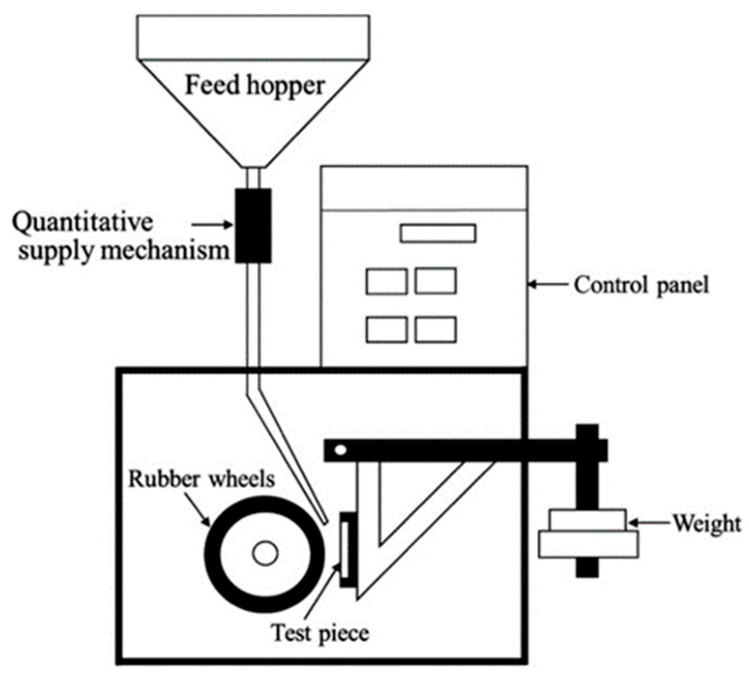
2. Materials and Methods

Two types of high-Cr MCCI with about 18 wt.% and 27 wt.% Cr based on 3 wt.% Mo, V, W, Co, with 3 wt.% C were manufactured as the tested materials (abbreviations 18Cr-MCCI and 27Cr-MCCI). Then, both were grouped as as-quenched (Q), as-tempered low temperature (TLT), as-tempered middle temperature (TMT), and as-tempered high temperature (THT) and were used as abrasion test specimens. Therefore, there were tested 8 specimens in total. The specimen-making process has been comprehensively introduced in our previous research [31]. Concisely, it can be explained that first, all the elements were melted using a high-induction furnace (about 50 kg of raw materials). Then, the melt is poured into a sand mold (Y-block shape) as shown in Figure 1. After that, the bottom part of the Y block was cut to a size of 50 mm × 50 mm × 5 mm. The chemical composition of materials was measured using SPECTROLAB (AMATEK, Inc., Berwyn, PA, USA). The exact results are given in Table 1.
The wear resistance of heat-treated HWCI or MCCI has better performance than that of as-cast or without-heat-treatment owing to the alteration of the austenite-into-martensite matrix and the crystallization of secondary carbides. In a previous study [32], 18Cr MCCI Q and 27Cr MCCI Q were first heated at 1273 K and 1323 K, respectively, and then cooled using the air-forced-cooling method. In this study, both materials were heated at the same temperature (1273 K) to ensure all materials were subjected to the same heat-treatment conditions. For the tempering group, the materials were heated at a temperature range of 653–813 K at 20 K intervals and then cooled at room temperature using the air-cooling method. After heat treatment, the entire surface of the material was ground to uniform surface roughness (≈0.2 μm) using a grinder (GS52PF; Kuroda Seiko Co., Ltd., Ebina, Japan). Meanwhile, cubic blocks (10 mm × 10 mm × 10 mm) were prepared for microstructure observation. Each block was first embedded in resin, then polished with silica sandpaper, in order: P 120, P 240, P 400, P 600, and P 1200. This was followed by polishing using 9 μm, 6 μm, and 3 μm diamond suspension paste, and then 1 μm alumina. After that, it was observed using an optical microscope (OM, Eclipse MA100, Nikon, Tokyo, Japan), scanning electron microscopy (SEM + EDS; JSM-6510A, JEOL, Tokyo, Japan), and X-ray diffraction (XRD, Ultima IV, Rigaku, Tokyo, Japan). In addition, it was also etched using 5% nitro-hydrochloric acid (HCl: 35–37% and HNO3: 69–70% at a ratio of 3:1). The carbide area ratio, which is assumed as the carbide volume fraction (CVF), was calculated using five SEM images and ImageJ.
Two types of Vickers hardness data were measured in this research. The first is microhardness, as the hardness of the material’s matrix obtained using the Future-Tech Co. (Kawasaki, Japan) FM-300. The second is macrohardness, as matrix hardness plus precipitated carbides. Before measurement, cubic blocks of each material were prepared (10 mm × 10 mm × 10 mm). The polishing steps followed the preparation for microstructure analysis as previously described. In addition, the relationship between the hardness and fracture toughness of the primary M7C3 carbide will be discussed. Such an approach is recommended for brittle materials [33] and can be used to substantiate the application of indentation fracture toughness measurements of M7C3 carbide for indicating the structural integrity of the material under study. In addition, the relationship between the hardness and fracture toughness of the primary M7C3 carbide will be discussed. The microhardness and fracture toughness measurements of the carbide were performed by the micro-indentation technique using the Future-Tech Co FM-300. Meanwhile, the hardness of the M2C carbide could not be measured due to the inappropriate indenter of micro-Vickers hardness used for the small M2C carbide. The loads of macro- and microhardness test are 98.1 N, and 4.9 N, respectively. The measurement of each hardness datum was obtained using the average value of 14 repetitions of the test.
A rubber wheel machine tester was utilized to investigate the abrasion behavior of each material. This machine test follows the ASTM G65 standard, and the scheme is shown in Figure 2. In addition to the influence of chemical composition or microstructure, the abrasive-wear behavior of materials is also influenced by various test parameters, such as the number of applied loads, test time, silica sand (hardness and size), and test distance. This study will only evaluate the influence of applied loads with different chemical compositions and heat treatments. Meanwhile, the influences of other factors on the three-body abrasive-wear characteristics of materials can be used as further research topics. Therefore, there were three different loads applied; 73.5, 147, and 196 N. The test was conducted at 100 Rpm for 360 s. The rate of abrasive wear was calculated by dividing the weight of material lost by the distance used, as written in Equation (1):
Wear rate = ∆m/πdtn
where ∆m is material weight loss; d is the diameter of the wheel; t is time; and n is rotating speed.
In addition, the silica sand used is silica sand with a size of 300 μm and a hardness of 1100 HV. The data used are the average of three repetitions of the test.

3. Results

3.1. Hardness of Each Experimental Alloy

In previous studies [19,34], it has been well-documented that material hardness is very important to investigate in wear evaluation even though the toughness also should be considered in certain cases. Therefore, the hardness of each experimental specimen with different treatments was analyzed in this study. It was explained earlier that two hardness data were measured in this work. They are microhardness, which is the hardness of the matrix, and macrohardness, which is the precipitated carbides and matrix. The results are shown in Figure 3. In the case of 18Cr MCCI, the Q material has higher hardness than the tempered specimen for both micro- and macrohardness. Moreover, the hardness decreases as the temperature of the tempering process increases. The same trend also occurs in the case of 27Cr MCCI, where the hardness decreases after the tempering process and continues to decrease as the tempering temperature increases. These findings are in agreement with other, previous results. In general, the metal will experience stress relieving during the tempering stage, which results in lower hardness values [8,19]. This phenomenon might also be the reason for the hardness reduction of these present alloys.
However, there is an interesting comparison of hardness data between 18Cr MCCI and 27Cr MCCI under the same heat-treatment conditions. This shows that micro- and macrohardness decrease with increasing Cr content. This result contradicts several previously published papers [11,35,36]. In other words, adding large amounts of transition metals, especially Cr, does not necessarily increase hardness. Further microstructural analysis will be conducted to understand the cause of this fact. Prior to explaining the microstructure condition of the material, from these data, it can be said that the hardest material found is 18Cr MCCI Q (microhardness about 721 HV, macrohardness about 982 HV) and the lowest is 27Cr MCCI (microhardness about 543 HV, macrohardness about 821 HV) after tempering at 813 K. In order to obtain clear knowledge of the effect of tempering temperature on material wear, three tempering temperature points were selected. Therefore, the lowest, middle, and highest tempering temperatures are selected, which are abbreviated as TLT, TMT, and THT, respectively.

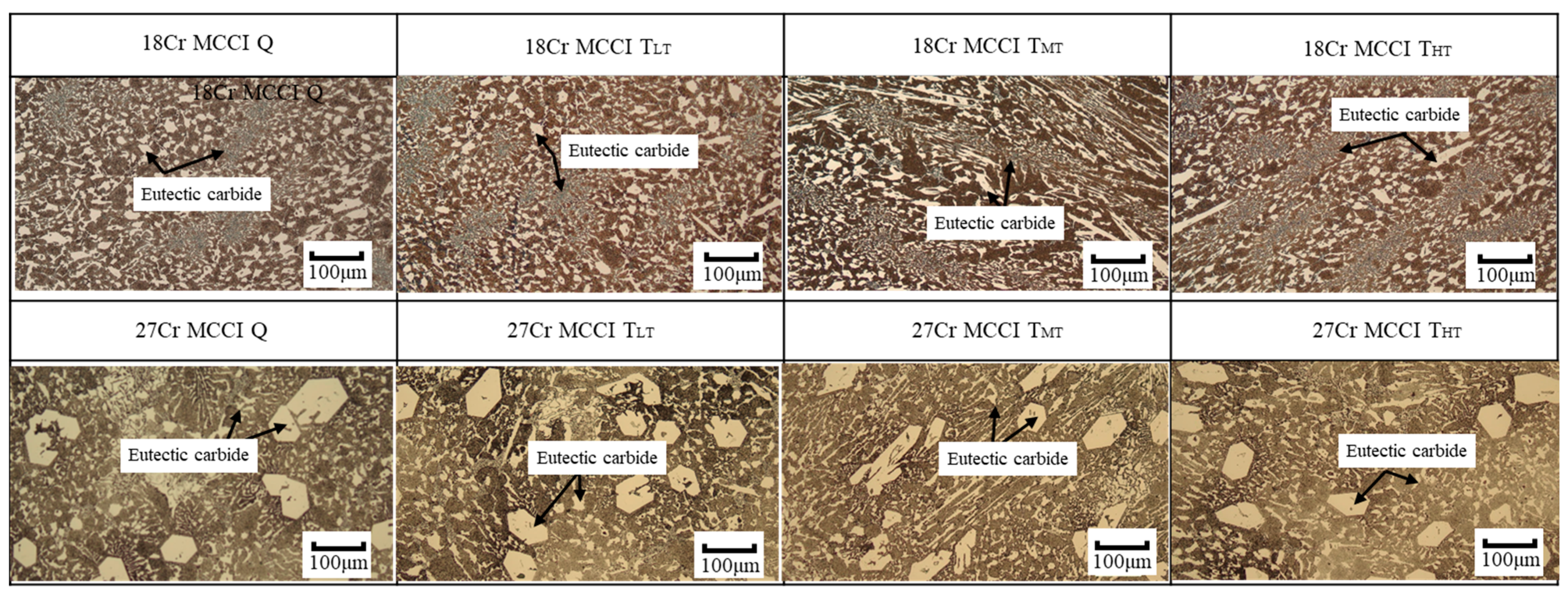
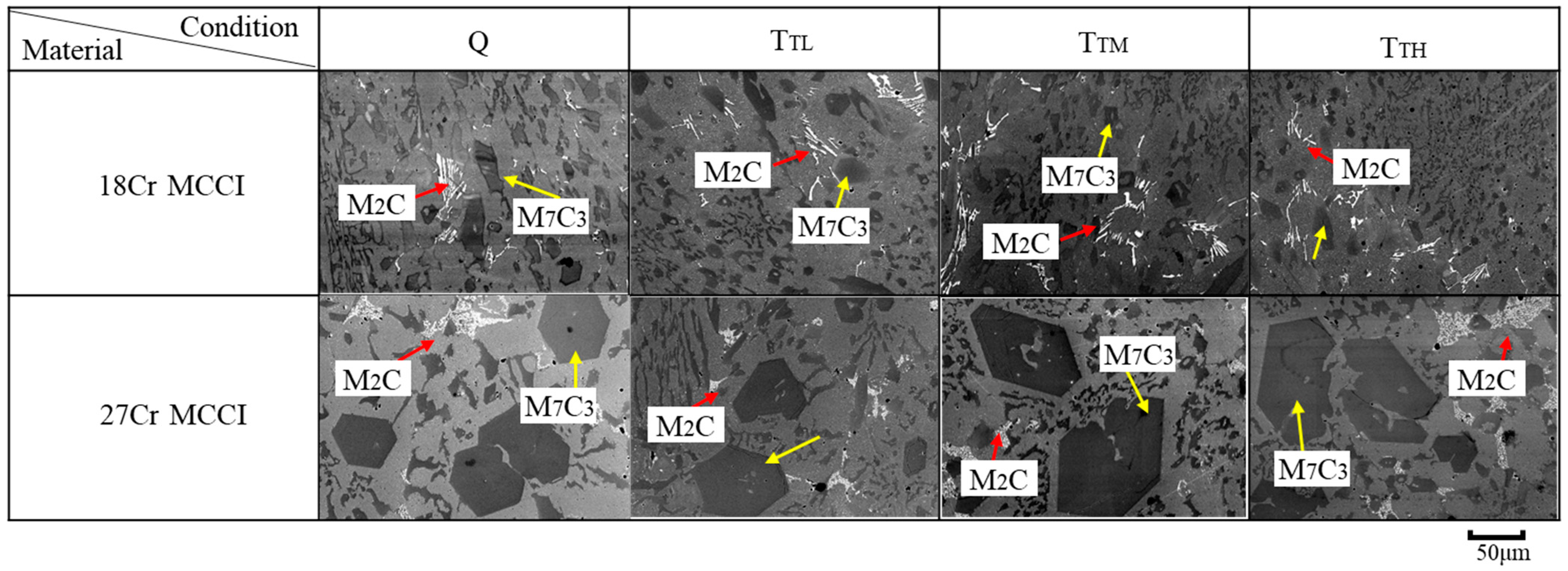
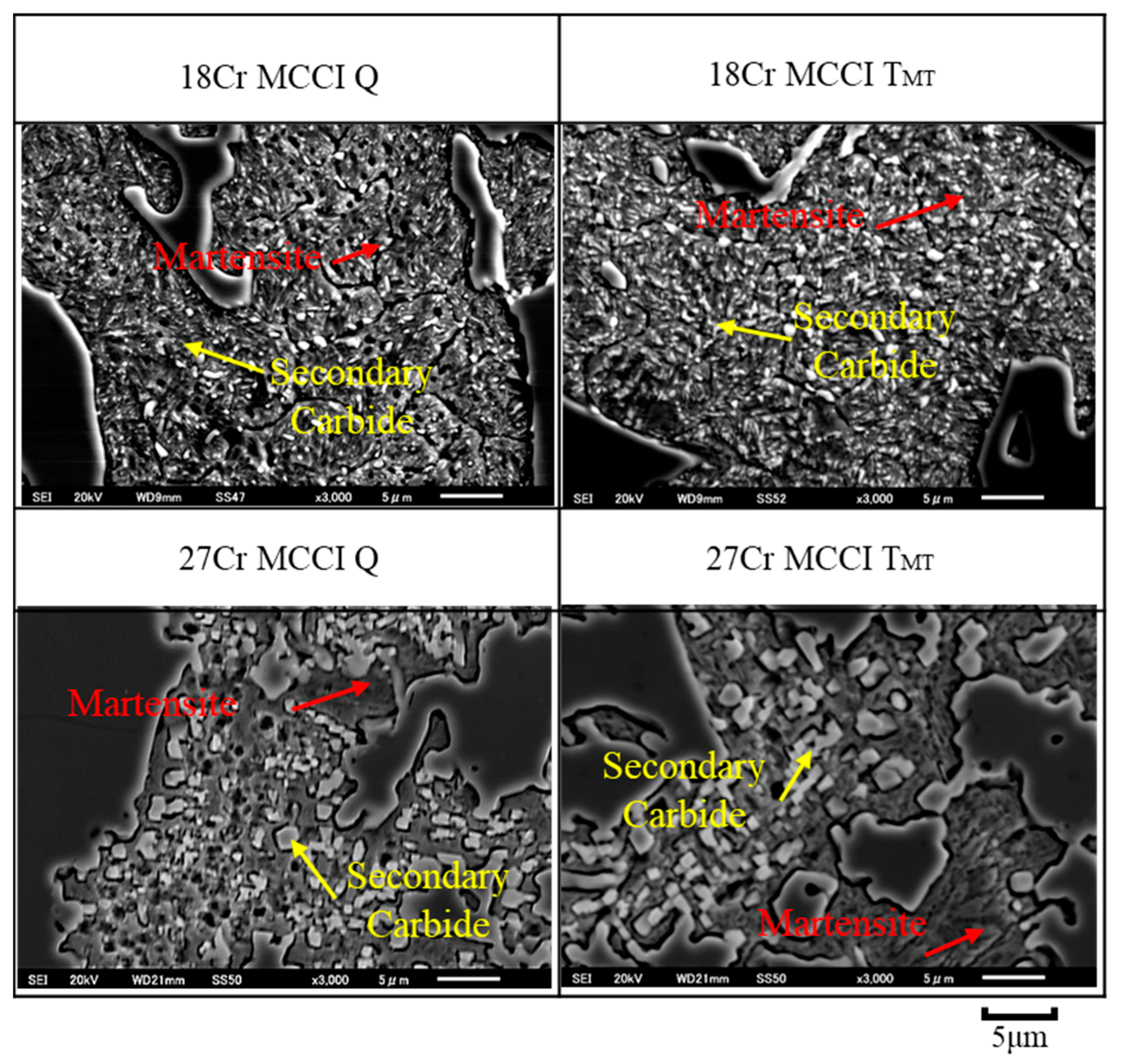
3.2. Microstructure of Experimental Alloys

Figure 4 shows the microstructure of each material after etching. The microstructure of 18Cr MCCI consists of a matrix shown by the brown color, and precipitated carbides shown by the lighter areas. There is no significant matrix color between Q and any of the TTL, TMT, or THT specimens. This indicates that the matrix is mostly changed from austenite to martensite and only a small amount of austenite is retained during the cooling process. Thus, the matrix type is not significantly different after the tempering process. The precipitated carbides are mostly evenly distributed in the microstructure. No significant difference in the shape or number of carbides was observed between the Q specimen and after tempering. Since carbides are stable at high temperatures or can be said to have high thermal stability, this might be related to the absence of differences in carbides obtained in both shape and fraction between Q and TTL or TMT or THT specimens. In the case of 27Cr MCCI, the microstructure also consists of matrix and precipitated carbides. As with 18Cr MCCI, no significant differences in matrix and carbides (shape and fraction) were obtained between Q and tempered specimens. However, the size of the carbides becomes larger as the amount of Cr increases, especially the hexagonal ones, when comparing 18Cr MCCI with 27Cr MCCI. From its shape, hexagonal carbide can be assumed to be M7C3, where the element Cr is the main element in the letter M. The investigations will be continued using SEM-EDS and XRD to provide a better understanding of the eutectic carbides type.
The kind of eutectic carbide can be known by pointwise analysis on SEM-EDS, as shown in Figure 5. The test was carried out on more than 10 times random carbide areas. The results show that there are two main precipitated carbide types: M7C3 and M2C. It can be said that the majority carbide type is M7C3 due to its higher percentage of Cr than others. The size of these carbides is larger as the amount of Cr added increases the size, and hexagonal is the primary shape of these carbides. The details of these primary carbides will be discussed in Section 3.5. In addition, there is no significant difference in the case of M2C either by increasing the amount of Cr or different destabilizing heat treatments. The shape of M2C is fish bonelike.
Using EDS mapping, the distribution of each element can be determined as shown in Figure 6. The Cr is embedded in the M7C3 carbide region of 18Cr MCCI TMT and 27Cr MCCI TMT. Filipovic et al. [37] reported that VC would precipitate on the hypoeutectic Fe–C–Cr microstructure during the solidification process with the addition of about 2.02 wt.% V. However, the VC on MC and M6C5 carbides did not precipitate in this study despite the higher amount of V (about 3 wt.%). Meanwhile, the V element was simultaneously embedded in M7C3 carbides. This different result might be due to differences in the overall chemical composition of the material. In addition, Mo and W elements form M2C carbides, which is consistent with previous studies. Elemental Co simultaneously occupies the matrix area with elemental Fe. This is owing to the nature of Co as a non-carbide-forming element and its role as a matrix reinforcement.
The secondary carbides can be found with lower magnification on the SEM, as shown in Figure 7. The type of these carbides is M23C6 and is not different in all specimens. The size of these carbides gets coarser as the amount of Cr increases. The average size of M23C6 is about 1.5 μm in the case of 18Cr MCCI, while it is about 3.7 μm in 27Cr MCCI. However, there is no visible difference between Q specimens and tempered specimens in both 18Cr MCCI and 27Cr MCCI due to the high thermal stability properties of carbides. In addition, the matrix of all specimens appears needlelike, indicating that the main matrix type is martensite.
As in the SEM-EDS results, XRD also detected the same type of carbide and matrix, as shown in Figure 8. There are M2C carbides occupied by Mo and W elements in either 18Cr MCCI Q or 27Cr MCCI Q. Cr and V were detected as M7C3 and M23C6 formed. In addition, there is an M3C carbide peak. Since the M3C peak is low, it is difficult to observe using SEM-EDS. Then, there is only the alpha phase indexed. In general, a small amount of retained austenite will remain in the microstructure after the destabilization heat-treatment process [13,30]. However, the retained austenite phase was difficult to find using XRD in this study. This indicates that there is only a very small amount of retained austenite after the quenching process. The difference between the results of this study and previous studies might be influenced by the cooling rate or holding time of the heat-treatment process.
The carbide volume fraction (CVF) is depicted in Figure 9. It shows that the CVFs of M7C3, M2C, and M23C6 in the case of 18Cr MCCI Q are about 21.13%, 2.40%, and 3.56%, respectively. These volume fractions did not change significantly after the tempering process. This can be used as evidence of the stability properties at high temperatures of each carbide. Therefore, the total CVF of this group of materials is about 27.09%. In the case of 27Cr MCCI Q, the CVFs of M7C3, M2C, and M23C6 are about 24.98%, 2.53%, and 4.58%, respectively. Just like 18Cr MCCI, there is no difference after the tempering process. Thus, the total of CVF is about 32.09%. This means that the average volume fraction of M7C3 and M23C6 carbides precipitated increases as the addition of Cr increases. Meanwhile, the same amount of W and Mo in both materials (18Cr MCCI and 27Cr MCCI) is associated with almost the same volume fraction of M2C carbides. When these data are related to the hardness of the material, the CVF is not consistent with the micro- or microhardness where the higher CVF has a lower hardness value. It can be understood that each transition metal added will react with element C to form each type of carbide due to the high-affinity nature of the element. Thus, more Cr element added will form more or larger carbides during the solidification process, as evidenced by the increase in CVF. This phenomenon will naturally deplete the amount of C in the material’s matrix region. In addition, during heat treatment, elemental Cr also still reacts with the remaining C in the matrix to form secondary carbides where a higher element of Cr will take more C, as evidenced by the coarser M23C6 of 27Cr MCCI than 18Cr MCCI. The coarsening of carbide might reduce the C element remaining in the matrix. These two conditions are associated with the decrease in hardness with the addition of Cr. However, because there is no significantly different microstructure evolution, for example, relatively same volume fraction of carbides of M7C3, M2C, M23C6 (secondary carbides), or matrix type (mainly as martensite) between quenched and tempered specimens either on 18Cr MCCI or 27Cr MCCI, therefore, the factor of hardness decrease can be said to be due to the phenomenon of relieving stress. The influence of all obtained results (hardness and microstructure) on the wear behavior of materials will be discussed in the next section.

3.3. The Abrasive-Wear Rate of Each Experimental Alloy

The abrasive-wear behavior of a material is affected by various test parameters, for example, the amount of applied load, test time, temperature, abrasive particle size, hardness, etc. In this study, the effect of the applied load was investigated, while other factors were maintained under the same conditions. The relationship between the number of applied loads and the wear characteristics of each experimental alloy is depicted in Figure 10. Atabaki et al. [38] and El-Aziz et al. [39] stated that the wear resistance of high-Cr white cast iron (HWCI) with the same Cr and C ratio will decrease as the load increases. The same result is also shown in both materials (18Cr MCCI and 27Cr MCCI) after the quenching process and with the tempering process. The wear rate of the material slightly increases with the increase in load. To provide a closer understanding of the actual engineering field, the investigation highlight the highest amount of load applied, as illustrated in Figure 11.
The wear rate of 18Cr MCCI Q (about 2.69 × 10⁻⁵ g/m) is lower than that of the tempered specimens. Since the hardness of the quenched material decreases during the tempering process due to relieving stress as described earlier, it might be a factor in the reduction of wear resistance in this case. However, the wear rates of TLT (about 4.12 × 10⁻⁵ g/m), TMT (about 4.29 × 10⁻⁵ g/m), and THT (about 4.22 × 10⁻⁵ g/m) are almost the same, inferring no different wear resistance among them, although the hardness decreases slightly as the tempering temperature increases. This means the wear performance of these materials is not affected by hardness. In addition, it is also not affected by the type of CVF, matrix, and carbide due to the same overall chemical composition. It should be influenced by other factors.
In the case of 27Cr MCCI, the wear performance shows fluctuating conditions as the tempering temperature increases. The wear rate Q (about 8.98 × 10⁻⁵ g/m) decreased after tempering at the lowest tempering temperature (about 7.91 × 10⁻⁵ g/m) and continued to decrease at middle temperatures (about 7.50 × 10⁻⁵ g/m). Then, the wear rate of the material again increased slightly after being tempered at the highest tempering temperature (about 7.94 × 10⁻⁵ g/m). Thus, the better wear resistance is TMT, while the lower one is Q. This condition is completely different from the case of 18Cr MCCI. Moreover, although the hardness decreases during tempering temperatures, the wear performance of 27Cr MCCI increases. This result contradicts previous articles reporting that higher hardness has better wear resistance [30,31]. It means that the tempering process can withstand the wear resistance of this material category.
In addition, the results also show that the wear resistance of 18Cr MCCI is better than that of 27Cr MCCI when compared under the same heat-treatment conditions. In the previous section, it has been systematically investigated that the concentration of C remaining in the matrix is lower as the Cr addition increases, which is evidenced by the decrease in microhardness. Thus, the decrease in wear resistance as the amount of Cr (18 to 27 wt.%) increases might be due to the lower hardness. Thus, the hardness is very important to consider in this case. However, the wear performance of materials will not necessarily be affected by hardness under all conditions, for example, in the case of 18Cr MCCI and 27Cr MCCI categories as described earlier. Therefore, the investigation will be continued from another point of view to provide a comprehensive explanation as discussed in the next section. However, from these data, it is found that the 18Cr MCCI Q has the best wear resistance properties, while the worst is 27Cr MCCI Q.

3.4. Abrasive-Wear Mechanisms of Each Experimental Alloy

To determine other factors affecting the wear performance of the materials, the abrasive-wear mechanism was investigated through the surface of the material after testing. The results are shown in Figure 12. Overall, a groove pattern can be found, which indicates that all specimens experienced three-body abrasive wear. At a lower magnification of the SEM (Figure 13), cutting marks along the matrix area are visible. The presence of this microcutting is believed to be due to the lower hardness of the matrix than the abrasive (1100 HV). Therefore, a more severe condition occurs in the tempered specimen due to the reduction in matrix hardness during the tempering process. However, no significant difference was observed between TLT, TMT, and THT. This condition is related to their abrasive-wear performance where a better worn surface has better abrasive-wear resistance. The same results were also observed when 18Cr MCCI was compared with 27Cr MCCI at the same heat-treatment condition. In addition, from worn surface observation, the M2C and matrix of all materials are simultaneously abraded by particles, indicating that there is no significantly different effect of M2C carbide between 18Cr MCCI and 27Cr MCCI on all heat-treatment conditions. Overall, 18Cr MCCI Q had a better worn surface, and the worst was 27Cr MCCI Q.
In the case of 27Cr MCCI, the worn surface shows that cutting marks can also be observed in the matrix region. It gets worse as the tempering temperature increases. This is owing to the lower microhardness (matrix only), as described in Section 3.1. In addition to the presence of microcutting, there is spalling in the M7C3 carbide region of Q. Nevertheless, the primary M7C3 carbide remains firm after testing in the case of the tempering process. In addition, there is no significantly different condition of M7C3 carbides between TLT, TMT, and THT. Since the condition of M7C3 after tempering is better than that of Q, it might affect the wear performance of each material. Therefore, the property of this primary M7C3 carbide should be considered, which will be discussed in Section 3.5. However, from these observations, it can be stated that the main abrasive-wear mechanism of 18Cr MCCI is microcutting. Meanwhile, carbide spalling is also involved in the case of 27Cr MCCI.

3.5. Evaluation of the Properties of M7C3 Carbide

In this study, only the properties of the primary carbide M7C3 was evaluated because only this type of carbide was found to stand firmly on the surface. The evaluation included size, hardness, and fracture toughness. The carbide size was measured using five SEM microphotographs. First, the primary M7C3 was colored using a paint application to increase the contrast with the other phases. Then, it was calculated with ImageJ. The results showed that the average size of 18Cr MCCI and 27Cr MCCI primary carbides did not change during the tempering stage owing to the high thermal stability of the carbides. However, the size increased significantly as the percentage of Cr increased due to segregation. The average carbide size of 18Cr MCCI is about 35 μm, while that of 27Cr MCCI is about 86 μm.
Micro-indentation was performed as an approximation technique to measure fracture toughness using Vickers microhardness [40]. Indentation was conducted on primary M7C3 carbides indicated by hexagonal shape. A schematic and an example of the primary carbide after being indented are shown in Figure 14a,b, respectively. To minimize data errors, pointwise analysis was performed on the indented M7C3 to examine the Cr and V peaks (main elements of M7C3) using SEM-EDS, as shown in Figure 14c. The calculation was obtained using Equation (2). The results are given in Table 2.
Kc = α E P 1 2 d 2 a 3 2
where Kc is the critical fracture toughness (Pa.m1/2), α is the calibration factor (0.026), E is Young’s modulus of M7C3 carbide (310 GPa) [32], P is the number of loads (2.9 N), a is the half-length of the crack, and d is the diagonal length of indentation.
The hardness of M7C3 in the 18Cr MCCI is higher than that of 27Cr MCCI under the same heat-treatment condition. It is understood that more Cr added will naturally segregate more elemental C. Thus, M7C3 carbides will be occupied by more C, resulting in larger and harder carbides. However, the carbide fracture toughness is contrary to the hardness data, which is very normal for metals. In general, the fracture toughness of the material will decrease as the hardness increases due to brittleness [41]. The results also showed that the fracture toughness slightly increased after tempering compared to Q in both materials. Based on this result, it is known that the lower fracture toughness of M7C3 in the 27Cr MCCI Q allows it to easily undergo spalling during testing. Therefore, the presence of large M7C3 carbides in the microstructure of 27Cr MCCI meant it was more likely to be peeled off to the tribosurface, which would deteriorate the wear resistance of the samples as the number of applied loads increased. The tendency of spalling can be effectively reduced by improving the fracture toughness of the primary carbide through the tempering process. Therefore, the wear resistance was improved by the tempering process. However, the wear resistance of this material will decrease after the tempering temperature becomes too high (THT). This might be caused by the significant hardness reduction at high temperatures of tempering. In addition, it can also be seen that the hardness of the material is the most important factor in the case of 18Cr MCCI. Although after the tempering process the fracture toughness of the carbide increases with the increase in tempering temperature, it does not provide better wear resistance and even worsens the wear resistance of 18Cr MCCI. It can be stated that the wear behavior of a material is greatly affected by hardness. However, once the material’s microstructure contains larger M7C3, the fracture toughness of carbides is very important to consider, which can be improved by suitable tempering temperature.

4. Conclusions

The abrasive-wear behavior of high-Cr MCCI with the addition of 3 wt.% C (eutectic range) at different tempering temperatures has been comprehensively investigated in this study. All the results obtained can be summarized as follows:
1.
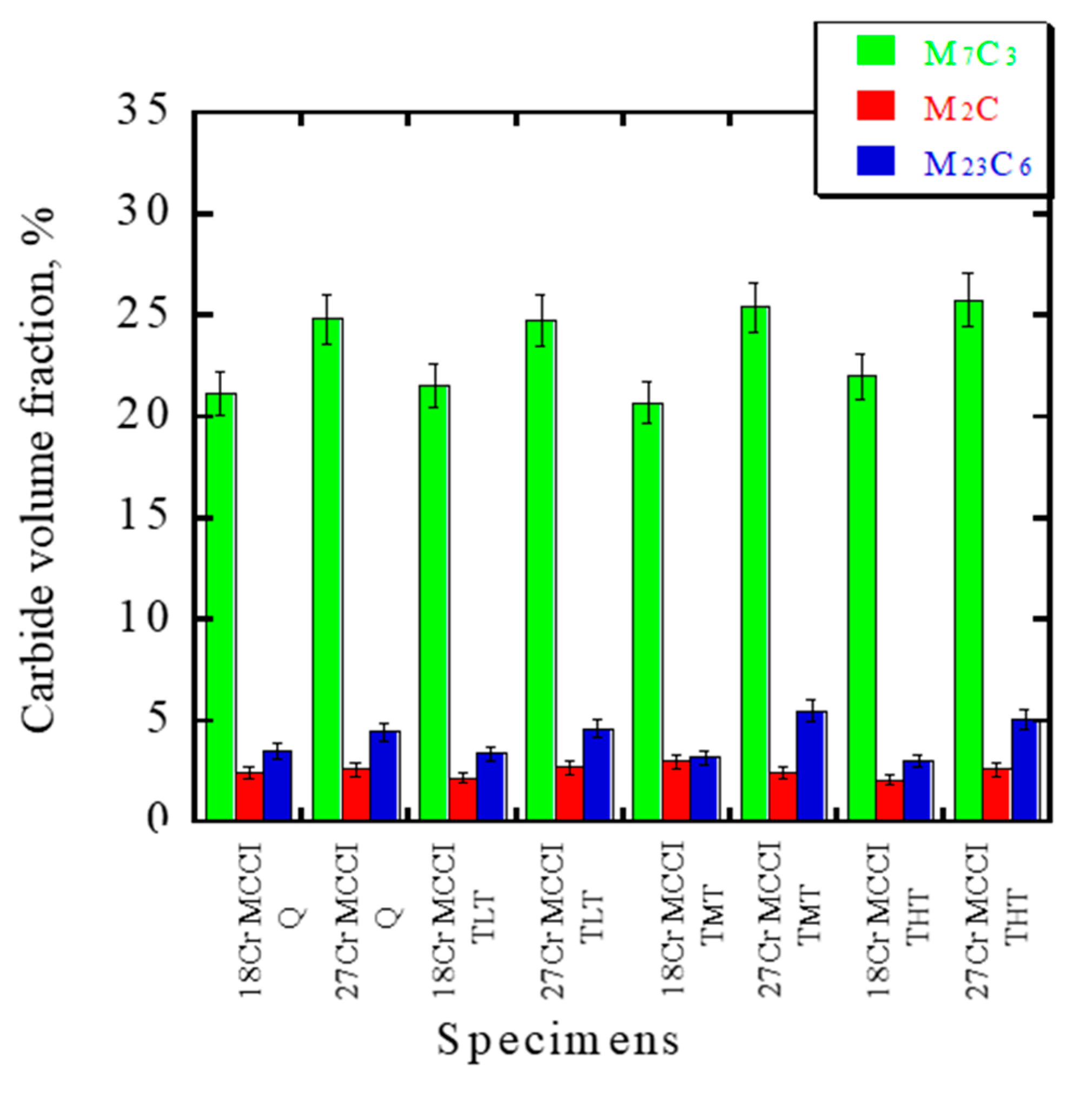
The size of M7C3 and secondary carbides (M23C6) is enlarged with an increased amount of Cr, which results in more CVF in total. However, there is no significant difference in the CVF of M2C between the two materials (18Cr MCCI and 27Cr MCCI) due to the same amount of Mo and W addition. In addition, there is no major difference in the matrix (mainly martensite) and CVF as the Cr addition and tempering temperature increase.
2.
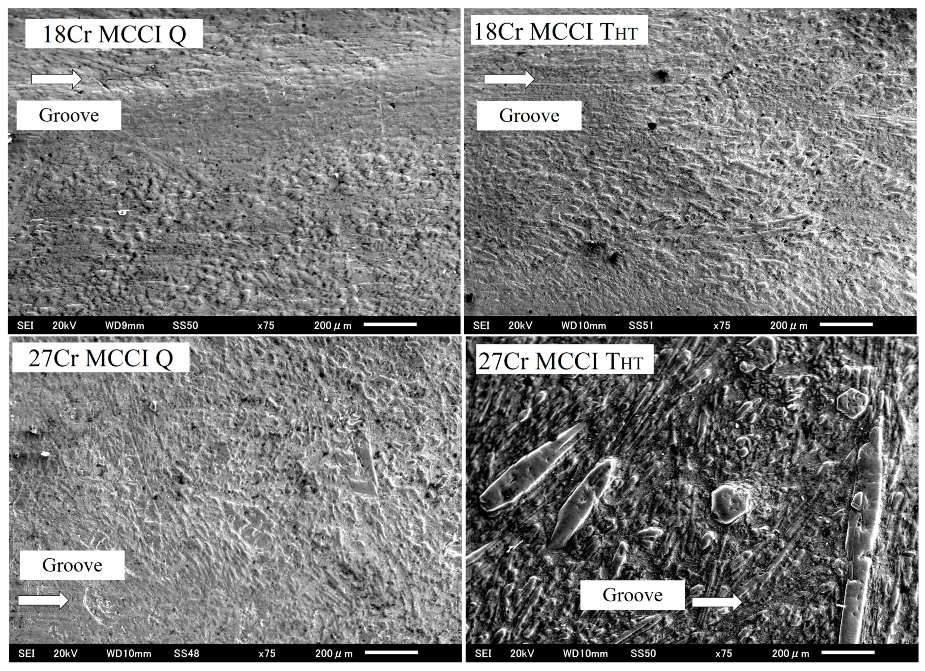
Although the main mechanism of abrasive wear is microcutting, the presence of carbide spalling in the case of 27Cr MCCI deteriorates the wear resistance of the alloy.
3.
The wear resistance of 27Cr MCCI is improved by the tempering process, although its hardness decreases. This is due to the higher fracture toughness level of the M7C3 carbide. However, the opposite result will occur if the tempering temperature is too high. Therefore, QTMT has better wear resistance in the case of 27Cr MCCI.
4.
The fracture toughness of the M7C3 carbide in the case of 18Cr MCCI also increases slightly with the tempering process. However, this does not lead to an increase in the wear resistance of the material. In general, the hardness of the material has a more pronounced effect on its wear resistance than the fracture toughness of separate carbide particles.
5.
The material with the best wear resistance is 18Cr MCCI Q, while the worst is 27Cr MCCI Q among all experimental alloys.

Author Contributions

Validation, K.S.; Formal analysis, R.H.P. and K.K.; Writing an original draft, Investigation, R.H.P.; Resources, K.S.; Data curation, Y.G.; Writing—review & editing, Y.G. and M.J.H.; Supervision, K.K. and K.S. All authors have read and agreed to the published version of the manuscript.

Funding

This research received no external funding.

Data Availability Statement

The data presented in this study are available upon request from the corresponding author.

Conflicts of Interest

The authors declare no conflict of interest.

References

  1. Robert, J.K. Wood. Friction, lubrication, and wear technology. In ASM Handbook; ASM International: Phoenix, AZ, USA, 2017; Volume 18, pp. 266–289. [Google Scholar]
  2. Jain, A.S.; Chang, H.W.; Tang, X.H.; Hinckley, B.; Zhang, M.X. Refinement of primary carbides in hypereutectic high-chromium cast irons: A review. J. Mater. Sci. 2020, 56, 999–1038. [Google Scholar] [CrossRef]
  3. Siekaniec, D.; Kopycinski, D.; Tyrala, E.; Guzik, E.; Szczesny, A. Optimisation of Solidification Structure and Properties of Hypoeutectic Chromium Cast Iron. Materials 2022, 15, 6243. [Google Scholar] [CrossRef] [PubMed]
  4. Dogan, O.N.; Laird, G.; Hawk, J.A. Solidification structure and abrasion resistance of high chromium white cast irons. Metal. Meter. Trans. A 1997, 28, 1315–1328. [Google Scholar] [CrossRef]
  5. Liu, Q.; Shibata, H.; Hedström, P.; Jönsson, P.G.; Nakajima, K. Dynamic precipitation behavior of secondary M7C3 carbides in Ti-alloyed high chromium Cast Iron. ISIJ Int. 2013, 53, 1237–1244. [Google Scholar] [CrossRef] [Green Version]
  6. Bedolla-Jacuinde, A.; Guerra, F.V.; Mejia, I.; Zuno-Silva, J.; Rainforth, M. Abrasive wear of V-Nb-Ti alloyed high-chromium white irons. Wear 2015, 332, 1006–1011. [Google Scholar] [CrossRef]
  7. Chen, Z.; Guo, Q.; Fu, H.; Zhi, X. Effect of heat treatment on microstructure and properties of modified hypereutectic high chromium cast iron. Mater. Test. 2022, 64, 33–54. [Google Scholar] [CrossRef]
  8. Gundlach, R.B.; Parks, J.L. Influence of abrasive hardness on the wear resistance of high chromium irons. Wear 1978, 46, 97–108. [Google Scholar] [CrossRef]
  9. Kositsyana, I.I.; Sagaradze, V.V.; Makarov, A.V.; Kozlova, A.N.; Ustyuzhaninova, A.I. Effect of structure on the properties of white chromium cast irons. Mater. Sci. Heat Treat. 1996, 38, 149–152. [Google Scholar] [CrossRef]
  10. Wiengmoon, A.; Chairuangsri, T.; Chomsang, N.; Poolthong, N.; Pearce, J.T.H. Effects of heat treatment on hardness and dry wear properties of a semi-solid processed Fe-27wt%Cr–2.9wt%C cast Iron. J. Mater. Sci. Technol. 2008, 24, 330–334. [Google Scholar]
  11. Scandian, C.; Boher, C.; de Mello, J.D.B.; Rézaï-Aria, F. Effect of molybdenum and chromium contents in sliding wear of high chromium white cast iron: The relationship between microstructure and wear. Wear 2009, 267, 301–408. [Google Scholar] [CrossRef] [Green Version]
  12. Efremenko, V.; Shimizu, K.; Chabak, Y. Effect of Destabilizing Heat Treatment on Solid-State Phase Transformation in High-Chromium Cast Irons. Metall. Mater. Trans. A 2013, 44, 5434–5446. [Google Scholar] [CrossRef]
  13. González-Pociño, A.; Asensio-Lozano, J.; Álvarez-Antolín, F.; García-Diez, A. Improvement of Impact Toughness and Abrasion Resistance of a 3C-25Cr-0.5Mo Alloy Using a Design of Experiment Statistical Technique: Microstructural Correlations after Heat Treatments. Metals 2021, 11, 595. [Google Scholar] [CrossRef]
  14. Wang, J.; Li, C.; Liu, H.; Yang, H.; Shen, B.; Gao, S.; Huang, S. The precipitation and transformation of secondary carbides in a high chromium cast iron. Mater. Charact. 2006, 56, 73–78. [Google Scholar] [CrossRef]
  15. Guitar, M.A.; Scheid, A.; Suárez, S.; Britz, D.; Guigou, M.D.; Mücklich, F. Secondary carbides in high chromium cast irons: An alternative approach to their morphological and spatial distribution characterization. Mater. Charact. 2018, 144, 621–630. [Google Scholar] [CrossRef]
  16. Jia, X.S.; Hao, Q.G.; Zuo, X.W.; Chen, N.L.; Rong, Y.H. High hardness and toughness of white cast iron: The proposal of a novel process. Mater. Sci. Eng. A 2014, 618, 96–103. [Google Scholar] [CrossRef]
  17. Zhi, X.; Xiang, J.; Fu, H.; Xiao, B. Effect of niobium on the as-cast microstructure of hypereutectic high chromium cast iron. Mater. Lett. 2008, 62, 857–860. [Google Scholar] [CrossRef]
  18. Liu, Q.; Zhang, H.; Wang, Q.; Nakajima, K. Effect of heat treatment on microstructure and mechanical properties of Ti-alloyed hypereutectic high chromium cast iron. ISIJ Int. 2012, 52, 2288–2294. [Google Scholar] [CrossRef] [Green Version]
  19. Ibrahim, K.M.; Nofal, A.A. Effect of titanium addition on structure and properties of the as-cast high Cr-Mo white iron. Int. J. Mater. Res. 2013, 103, 362–370. [Google Scholar] [CrossRef]
  20. Chung, R.J.; Tang, X.; Li, D.Y.; Hinckley, B.; Dolman, K. Effects of titanium addition on microstructure and wear resistance of hypereutectic high chromium cast iron Fe–25 wt%Cr–4 wt%C. Wear 2009, 267, 356–361. [Google Scholar] [CrossRef]
  21. Chung, R.J.; Tang, X.; Li, D.Y.; Hinckley, B.; Dolman, K. Microstructure refinement of hypereutectic high Cr cast irons using hard carbide-forming elements for improved wear resistance. Wear 2013, 301, 695–706. [Google Scholar] [CrossRef]
  22. Arnoldo, B.J.; Guerra, F.; Mejia, I.; Vera, U. Niobium additions to a 15%Cr–3%C white iron and its effects on the microstructure and on abrasive wear behavior. Metals 2019, 9, 1321. [Google Scholar] [CrossRef] [Green Version]
  23. Pourasiabi, H.; Gates, J.D. Effects of chromium carbide volume fraction on high-stress abrasion performance of NbC-bearing high chromium white cast irons. Wear 2022, 498–499, 204312. [Google Scholar] [CrossRef]
  24. Coronado, J.J. Effect of (Fe, Cr)7C3 carbide orientation on abrasive wear resistance and fracture toughness. Wear 2011, 270, 287–293. [Google Scholar] [CrossRef]
  25. Zhou, Y.; Yang, Y.; Yang, J.; Hao, F.; Li, D.; Ren, X.; Yang, Q. Effect of Ti additive on (Cr, Fe)7C3 carbide in arc surfacing layer and its refined mechanism. Appl. Surf. 2012, 258, 6653–6659. [Google Scholar] [CrossRef]
  26. Efremenko, V.G.; Chabak, Y.G.; Lekatou, A.; Karantzalis, A.E.; Shimizu, K.; Fedun, V.I.; Azarkhov, A.Y.; Efremenko, A.V. Pulsed plasma deposition of Fe-C-Cr-W coating on high-Cr-cast iron: Effect of layered morphology and heat treatment on the microstructure and hardness. Surf. Coat. Technol. 2016, 304, 293–305. [Google Scholar] [CrossRef] [Green Version]
  27. Matsubara, Y.; Sasaguri, N.; Shimizu, K.; Yu, S.K. Solidification and abrasion wear of white cast irons alloyed with 20% carbide forming elements. Wear 2001, 250, 502–510. [Google Scholar] [CrossRef]
  28. de Mello, J.D.B.; Polycarpou, A.A. Abrasive wear mechanism of multi-components ferrous alloys abraded by soft, fine abrasive particles. Wear 2010, 269, 911–920. [Google Scholar] [CrossRef]
  29. Liu, T.; Sun, J.; Xiao, Z.; He, J.; Shi, W.; Cui, C. Effect of Multi-Element Microalloying on the Structure and Properties of HighChromium Cast Iron. Materials 2023, 16, 3292. [Google Scholar] [CrossRef]
  30. Kusumoto, K.; Shimizu, K.; Yaer, X.; Zhang, Y.; Ota, Y.; Ito, J. Abrasive wear characteristics of Fe-2C-5Cr-5Mo-5W-5Nb multi-component white cast iron. Wear 2017, 376–377, 22–29. [Google Scholar] [CrossRef]
  31. Purba, R.H.; Shimizu, K.; Kusumoto, K.; Gaqi, Y.; Huq, M.J. A study of the three-body abrasive wear resistance of 5V/5Nb-5Cr-5Mo-5W-5Co-Fe multicomponent cast alloys with different carbon percentages. Materials 2023, 16, 3102. [Google Scholar] [CrossRef]
  32. Purba, R.H.; Shimizu, K.; Kusumoto, K.; Gaqi, Y.; Todaka, T. Effect of boron addition on three-body abrasive wear charac-teristics of high chromium based multi-component white cast iron. Mater. Chem. Phys. 2022, 275, 125232. [Google Scholar] [CrossRef]
  33. Kulyk, V.; Duriagina, Z.; Vasyliv, B.; Vavrukh, V.; Kovbasiuk, T.; Lyutyy, P.; Vira, V. The Effect of Sintering Temperature on the Phase Composition, Microstructure, and Mechanical Properties of Yttria-Stabilized Zirconia. Materials 2022, 15, 2707. [Google Scholar] [CrossRef]
  34. Natarajan, S.; Anand, E.E.; Akhiles, K.S.; Rajagopal, A.; Nambiar, P.P. Effect of graphite addition on the microstructure, hardness, and abrasive weasr behavior of plasma spayed NiCrBSi coatings. Mater. Chem. Phys. 2016, 175, 100–106. [Google Scholar] [CrossRef]
  35. Fernández, I.; Belzunce, F. Wear and oxidation behaviour of high chromium white cast irons. Mater. Charact. 2008, 59, 669–674. [Google Scholar] [CrossRef]
  36. Tang, X.H.; Li, L.; Hinckley, B.; Dolman, K.; Parent, L.; Li, D.Y. Beneficial effects of the core-shell structure of primary carbides in high-Cr (45 wt%) white cast irons on their mechanical behavior and wear resistance. Tribol. Lett. 2015, 58, 44. [Google Scholar] [CrossRef]
  37. Filipovic, M.; Kamberovic, Z.; Korac, M.; Jordovic, B. Effect of niobium and vanadium additions on as-cast microstructure and properties of hypoeutectic Fe-Cr-C alloy. ISIJ Int. 2013, 53, 2160–2166. [Google Scholar] [CrossRef] [Green Version]
  38. Atabaki, M.M.; Jafari, S.; Abdollah-pour, H. Abrasive wear behavior of high chromium cast iron and hadfield steel-a comparison. J. Iron Steel Res. Int. 2012, 19, 43–50. [Google Scholar] [CrossRef]
  39. El-Aziz, K.A.; Zohdy, K.; Saber, D.; Sallam, H.E.M. Wear and corrosion behavior of high-cr white cast iron alloys in different corrosive media. J. Bio-Tribo-Corros. 2015, 1, 25. [Google Scholar] [CrossRef] [Green Version]
  40. JIS R 1607:2010; Testing Method for Fracture Toughness of Fine Ceramics at Room Temperature. Japan Industrial Standard: Tokyo, Japan, 2010.
  41. Keough, J.R.; Hayrynen, K.L. Cast Iron Science and Technology ASM Handbook, 1A; ASM International: Phoenix, AZ, USA, 2017; pp. 275–283. [Google Scholar]
Figure 1. Y-block shape and dimensions of each alloy.
Lubricants 11 00285 g001
Figure 2. Test scheme of rubber wheel abrasion machine.
Lubricants 11 00285 g002
Figure 3. The hardness data (micro and macro) of each material with different heat-treatment conditions.
Lubricants 11 00285 g003
Figure 4. Observation of the microstructure of each experimental alloy obtained by optical microscopy.
Lubricants 11 00285 g004
Figure 5. Observation of eutectic carbide types on each studied material using SEM-EDS.
Lubricants 11 00285 g005
Figure 6. EDS mapping of each added element distribution of representative material.
Lubricants 11 00285 g006
Figure 7. Observation of fine secondary carbide and the matrix types of representative materials.
Lubricants 11 00285 g007
Figure 8. XRD data of representative materials after quenching.
Lubricants 11 00285 g008
Figure 9. Volume fraction of precipitated carbide in all materials microstructure.
Lubricants 11 00285 g009
Figure 10. The wear rate of each experimental alloy as a function of applied loads.
Lubricants 11 00285 g010
Figure 11. The abrasive-wear rate of each experimental alloy at an applied load of 196 N.
Lubricants 11 00285 g011
Figure 12. Surfaces of representative materials after being tested under high load.
Lubricants 11 00285 g012
Figure 13. Observation of the most abraded surface after being tested at high load to determine the wear mechanism.
Lubricants 11 00285 g013
Figure 14. (a) The schematic micro-indentation; and (b,c) crack and EDX peak of the primary M7C3 carbide of 27Cr MCCI Q as the representative, respectively.
Lubricants 11 00285 g014
Table 1. The chemical composition of experimental alloys.
SpecimenCCrMoWVCoFe
18Cr MCCI2.9816.582.712.943.012.73Bal.
27Cr MCCI3.1027.042.902.882.752.84Bal.
Table 2. Hardness and fracture toughness of M7C3 carbide.
MaterialsHardness
(HV)
Fracture Toughness
(MPa.m1/2)
18Cr MCCI Q1567.13  ±  39.442.74  ±  0.1
18Cr MCCI TLT1432.06  ±  55.133.49  ±  0.5
18Cr MCCI TMT1428.67  ±  47.043.50  ±  0.3
18Cr MCCI THT1427.25  ±  63.513.53  ±  0.3
27Cr MCCI Q1677.51  ±  77.391.32  ±  0.7
27Cr MCCI TLT1599.63  ±  45.472.05  ±  0.2
27Cr MCCI TMT1560.44  ±  87.472.24  ±  0.4
27Cr MCCI THT1589.60  ±  26.592.55  ±  0.1
Disclaimer/Publisher’s Note: The statements, opinions and data contained in all publications are solely those of the individual author(s) and contributor(s) and not of MDPI and/or the editor(s). MDPI and/or the editor(s) disclaim responsibility for any injury to people or property resulting from any ideas, methods, instructions or products referred to in the content.

