Article

Wear Resistance of In Situ NbC-Reinforced Laser Cladding Ni45 Coatings

1
Key Laboratory of Advanced Functional Materials, Ministry of Education, Department of Materials Science and Engineering, Beijing University of Technology, Beijing 100124, China
2
College of Automobile and Mechanical Engineering, Changsha University of Science and Technology, Changsha 410114, China
*
Author to whom correspondence should be addressed.
Lubricants 2023, 11(8), 316; https://doi.org/10.3390/lubricants11080316
Submission received: 27 June 2023 / Revised: 19 July 2023 / Accepted: 25 July 2023 / Published: 26 July 2023
(This article belongs to the Special Issue Laser Surface Engineering for Tribology)

Abstract

:
In situ NbC-reinforced laser cladding Ni45 coatings have the advantages of high bond strengths, low dilution rates, small heat-affected zones and good wear resistance and have broad application prospects in the field of surface strengthening and repair of workpieces such as automotive molds and engine turbines. Previous studies have mostly used pure niobium powder for in situ synthesis to prepare Ni-based NbC coatings with a high production cost. In this paper, NbC was successfully synthesized in situ in Ni45 powder using inexpensive FeNb65 and Cr3C2. The prepared coating has a uniform microstructure and excellent wear resistance, and the reinforced phases are mainly NbC and Cr23C6. Coating 4# with 25 wt.% FeNb65 + Cr3C2 has the highest microhardness of 776.3HV0.2, about 1.45 times that of the Ni45 coating, and its wear resistance is 36.36 min/mg, about 60.6 times that of the Cr12MoV steel base material and about 23.76 times that of the Ni45 coating.

1. Introduction

Laser cladding has the advantages of a low dilution rate and a fast cooling rate [1,2,3,4]. It may be used to strengthen material surfaces or to repair the surface of damaged materials and has very broad application prospects [5,6,7]. Metal-based composite coatings are high-quality coatings prepared by mixing self-soluble alloy powders with hard-phase powders by laser cladding [8,9,10]. They have the advantages of high bond strengths, small heat-affected zones, high microhardnesses, and good wear resistance. Nickel-based NbC composite coatings are widely used in the surface strengthening and repair of automotive molds, engine turbines, and combustion turbine blades due to their high microhardness and good wear resistance [11,12,13,14,15].
According to the formation method of hard ceramic phases within the coatings, coating preparation methods can be categorized into the direct addition method and the in situ synthesis method. The direct addition method is convenient and fast, but the hard ceramic phase is less compatible with the substrate. The in situ synthesis method is the main method of coating preparation, as the hard ceramic phase is uniformly distributed and well combined with the substrate. Several scholars have tried to add a NbC hard ceramic phase to coatings by in situ synthesis. Initially, graphite and pure niobium powder were used to synthesize NbC in situ [16,17]. However, due to the large difference in density between graphite and metal powder, graphite tends to float on the surface of the mixed powder when the powder is mixed, resulting in large differences in the organization of different regions of the coating. In addition, graphite has a low ignition point and can be easily burned during laser cladding, thus seriously affecting the stability of the composition in the coating. To solve this problem, the teams of Chang Baohua at Tsinghua University and Tianbiao Yu at Northeastern University tried to replace graphite with B4C to provide a sufficient amount of carbon for the formation of hard ceramic phases in the coatings [18,19]. Fu Hanguang’s team at Beijing University of Technology tried to replace graphite with Cr3C2 in an in situ synthesis reaction [20]. While solving the problem of graphite burnout, the added Cr elements can also form hard ceramic phases such as Cr23C6 and Cr7C3 to further increase the microhardness of the coating. In previous studies of NiCrBSi-NbC composite coatings, the Nb element was mostly provided in the coating by adding pure niobium powder. However, due to the high price of pure niobium powder and its high melting point of 2468 °C, it is not feasible to apply it in practical production. In this paper, we try to use FeNb65 (melting point 1570–1650 °C), which is inexpensive and has a low melting point, to replace pure niobium powder. A NiCrBSi-NbC coating with excellent wear resistance and a low price was prepared by in situ synthesis of NbC with Cr3C2. The microstructure and wear resistance were also tested and analyzed, expecting to provide a reference for the application of in situ NbC-reinforced laser melting of nickel-based composite coatings.

2. Experiment

2.1. Materials

The laser cladding experiment was carried out on Cr12MoV die steel with dimensions of 12 mm × 60 mm × 100 mm. Before the test, the upper surface of the Cr12MoV steel substrate was polished with an angle grinder to remove rust. Subsequently, cotton dipped in acetone was used to wipe off the grease on the surface of the substrate as well as any residual debris from the grinding process. The laser cladding material was Ni45 powder produced by Beikuang New Material Technology Co., Ltd., Beijing, China., which is a standard spherical powder in the particle size range of 45~105 μm. The specific composition of Cr12MoV steel and Ni45 powder is shown in Table 1. The materials used for the in situ synthesis of NbC were 45~105 μm FeNb65 and Cr3C2, both of which were purchased from Xing Rongyuan Technology Co., Ltd., Beijing, China. The theoretical mass fraction of Nb in FeNb65 is 65 wt.%, and the actual mass share is 64.76 wt.%. The atomic ratio of Cr to C in Cr3C2 is 3:2, and the mass fractions of Cr and C are 86.7% and 13.3%. The SEM morphology photographs of FeNb65 and Cr3C2 are shown in Figure 1. Initially, FeNb65 and Cr3C2 were mixed according to a 1:1 molar ratio of Nb to C. Subsequently, a mixed powder of FeNb65 and the Cr3C2 and Ni45 powder was placed into a ball mill and mixed well according to different ratios. The prepared powders were put into a drying oven at a constant temperature of 80 °C for 2 h and set aside. The coating number and composition design are shown in Table 2.

2.2. Laser Parameters

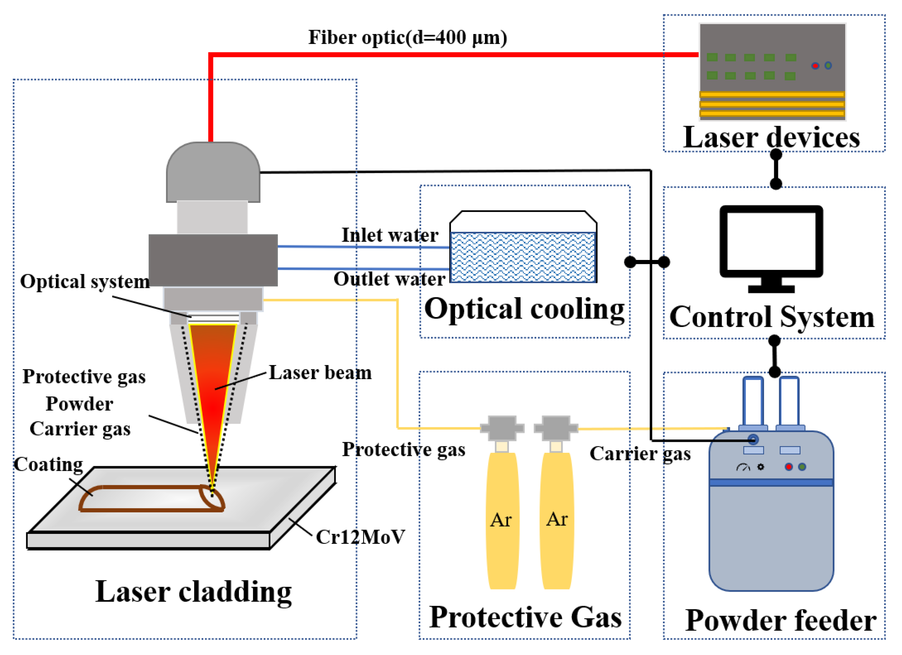
A YLS-6000-S2 fiber laser made by IPG of Oxford, MA, USA. was used for the test, with a maximum output power of 6000 W. The laser system generates a continuous laser with a wavelength of 1070 nm and transmits it through the fiber to the cladding head, where it acts on the substrate in a square spot of 5 mm × 5 mm. The melting head was driven by a six-axis linkage robot from ABB. In addition, an intra-optical coaxial powder feeder was connected to the cladding head to transport the powder. High-purity argon gas (99.99% purity) at 15 L/min was fed into the laser cladding process to avoid oxidation of the melt pool. A schematic diagram of laser cladding is shown in Figure 2. The process parameters of laser cladding were as follows: laser power, 2100 w; powder feeding rate, 15 g/min; scanning speed, 4 mm/s; and lap rate, 32%.

2.3. Microstructure Observation

Metallographic specimens were cut from a single coating in the direction perpendicular to the coating and mechanically ground in a grinding and polishing machine with 240 mesh, 400 mesh, 1000 mesh, 1500 mesh, 2000 mesh and 3000 mesh SiC sandpaper in that order. It was subsequently polished with a diamond polishing paste with a particle size of W2.5. The finished specimens were etched with aqua regia (HNO3:HCl = 1:3) for 22 s. The microstructure of the coatings was observed using a scanning electron microscope (ZEISS Gemini SEM 300 in Germany) and elemental analysis was performed with an additional energy spectrum probe (EDS). A 19 mm × 12 mm × 12 mm specimen was cut from the coating, and the phase composition of the coating was analyzed using a Cu-Kα radiation X-ray diffractometer (BRUKER D8 Advance in Germany) after mechanical grinding with 240 and 400 mesh SiC sandpaper in turn. The specific parameters were as follows: tube voltage, 40 kV; tube current, 40 mA; scanning speed, 8°/min; scanning range, 20~90° coupled continuous scanning; and step size, 0.02°.

2.4. Microhardness and Wear Resistance

To ensure the accuracy of the microhardness test, the specimens were mechanically ground on a grinding and polishing machine with SiC sandpaper of 240, 400, 1000, 1500, 2000 and 3000 mesh in that order. The prepared specimens were measured using a microhardness tester (MICRO-MET-5103 in Germany) with an indenter load of 1.96 N and a loading time of 10 s. Five locations were selected at 250 μm intervals starting from the upper part of the coating and the average value was taken as the microhardness at that location after removing the best value.
To ensure the testing accuracy of coating wear resistance, specimens of 19 mm × 12 mm × 12 mm were mechanically ground using 240 mesh and 400 mesh SiC sandpaper in turn. The prepared specimens were subjected to a friction wear test using a high-speed ring block friction wear tester (Jnstart MRH-3W in China). According to GB/T 3960-1983, the test load was 196 N, the wear time was 2 h, the speed as 200 r/min, the hardness of the grinding ring was 60 HRC and the material was GCr15 steel. The specimens were ultrasonically cleaned with anhydrous ethanol before and after the frictional wear test, and the weight was recorded by weighing them several times on a balance with an accuracy of 0.1 mg. The wear weight loss of the specimens was determined and the wear resistance of the coating was calculated. The surface morphology and roughness of the worn specimens were observed with a laser confocal microscope (OLS40-CB in Japan) and a scanning electron microscope.

3. Results and Discussion

3.1. Microstructure Analysis

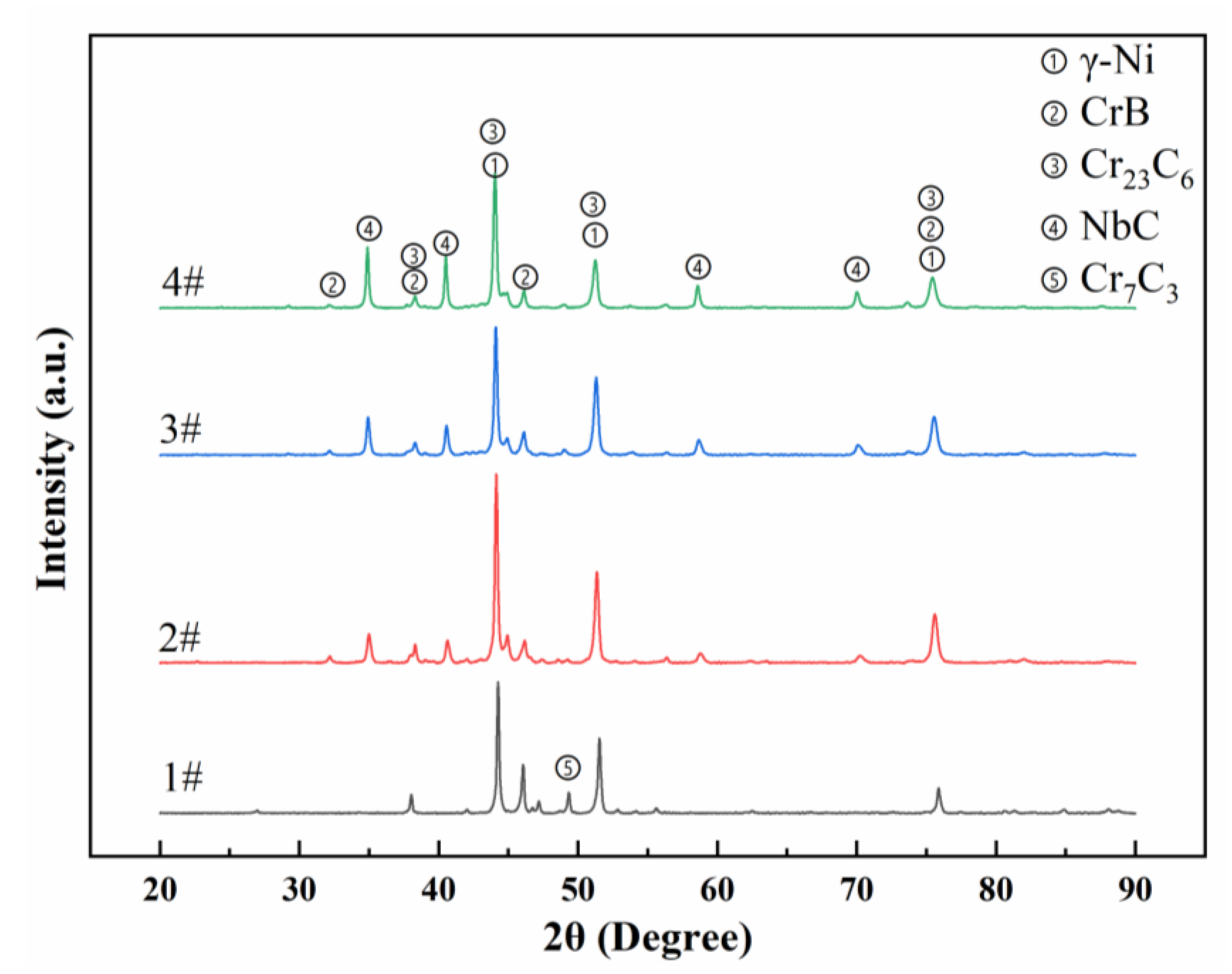
The coatings with different compositions were analyzed by an X-ray diffractometer and the results are shown in Figure 3. By comparing the standard diffraction cards and using Jade 6 analysis software, it can be seen that the possible phases of coating 1# are γ-Ni, Cr23C6, Cr7C3 and CrB. Coatings 2#, 3# and 4# are probably γ-Ni, Cr23C6, CrB and NbC. With the increase in NbC content, the intensity of the three NbC diffraction peaks at 35°, 41° and 58° increases significantly. The results show that it is feasible to synthesize a NbC hard ceramic phase using ferric niobium and Cr3C2 for nickel-based coatings.
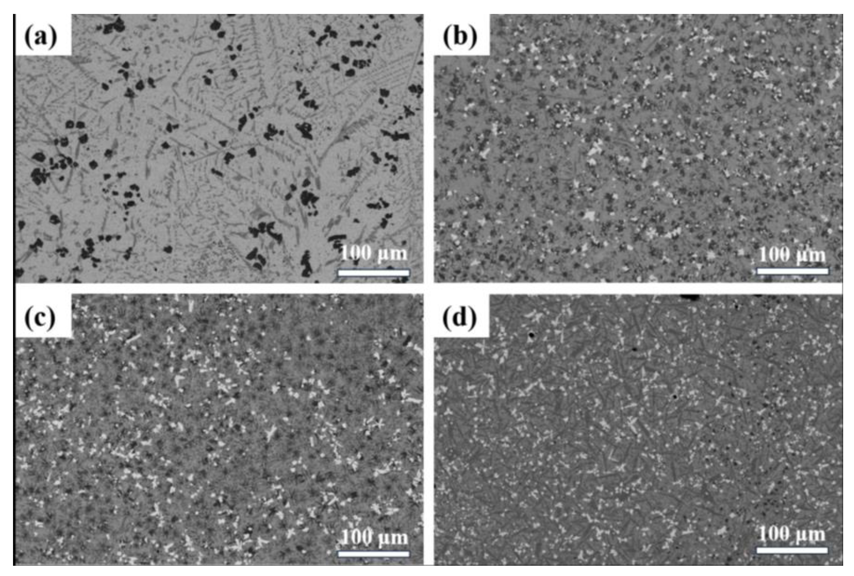
The microstructure photos in Figure 4 show that a large number of bright white phases are distributed inside coatings 2#, 3# and 4#, which is the typical morphology of the NbC phase. This result confirms that the in situ synthesis reaction of Cr3C2 and FeNb65 to generate NbC hard ceramic phases is feasible. Moreover, due to the similar density of NbC and Ni matrices, there is no obvious concentration gradient in each phase in the coating and NbC is uniformly distributed in the coating. In addition, the presence of long gray stripes, black block phases and gray irregularly shaped phases in the coating can be observed in the four sets of images.
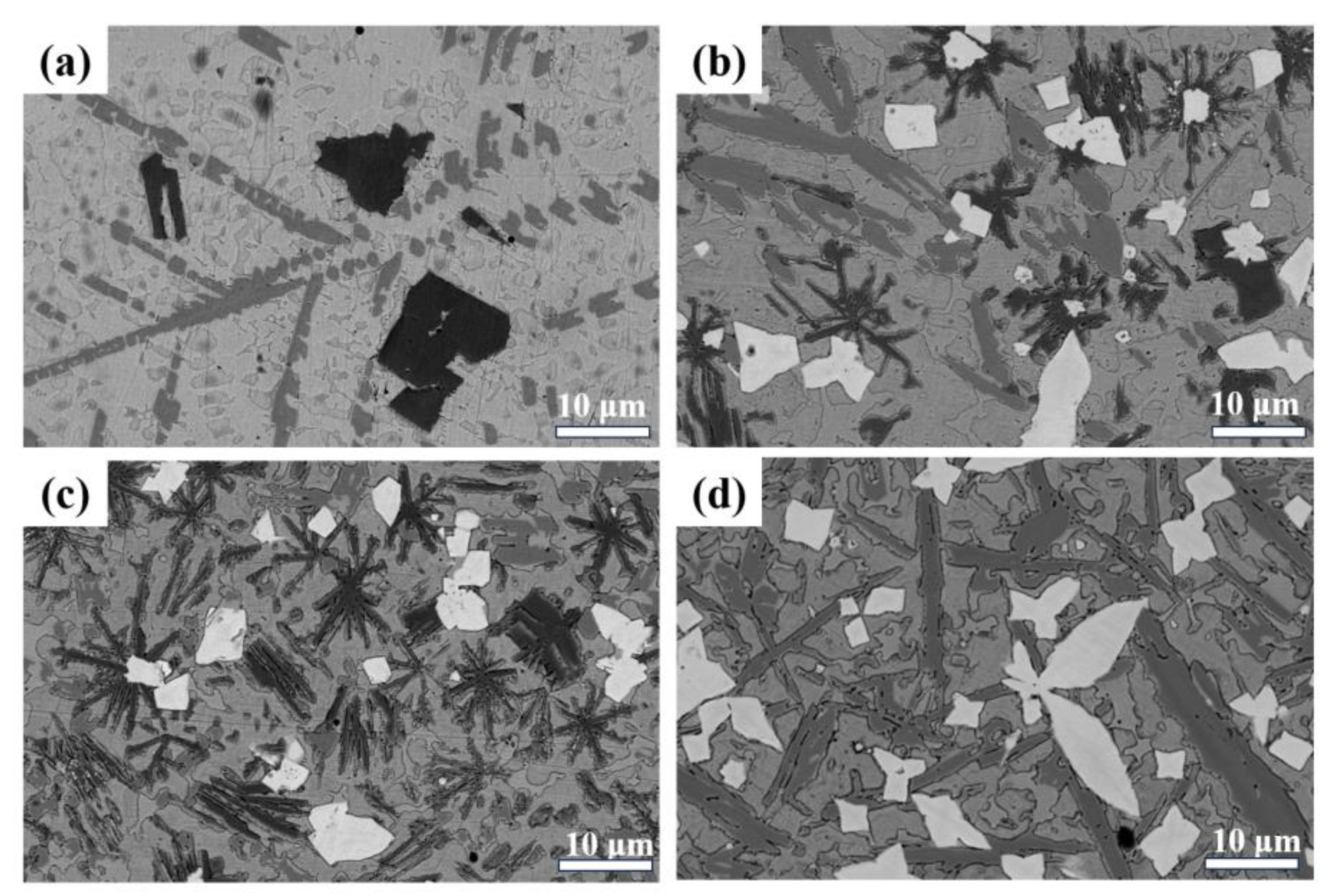
To further analyze the morphology of the phases within the coating, the microstructure morphology of the coating was observed at a higher magnification. The results are shown in Figure 5. Coatings 2# and 3# have irregular polygonal blocks of the NbC hard ceramic phase, while in coating 4#, the morphology of NbC is mostly regular quadrilateral and cross shaped. This is caused by the difference in the Nb content in the melt pool. When the amount of Nb in the melt pool is comparatively low, the nucleation and growth of NbC is limited. As the NbC content increases, the octahedral structure of NbC grows along the [100] direction, forming polygonal or cross-shaped structures with regular edges [9]. In addition, long black phases cross-arranged in clusters were observed in coatings 2# and 3#. In contrast, in specimen 4#, these black clustered phases disappeared and were replaced by black block phases. The long gray stripe phase became thicker and its color was clearly visible in BSE mode, presumably due to the solid solution of some elements of the cluster phase within the long gray stripe phase. The composition of the various phases needs to be further analyzed.
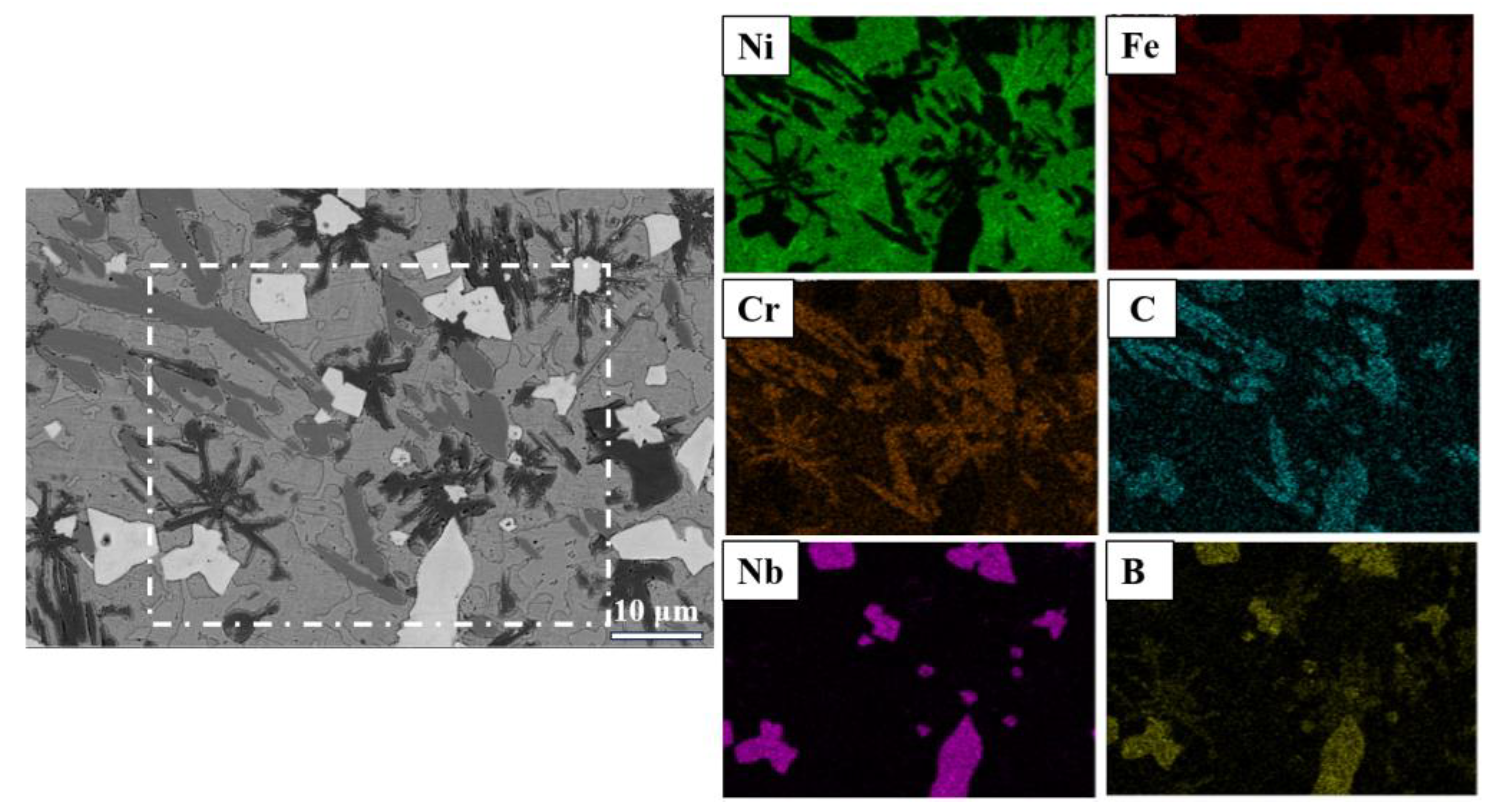
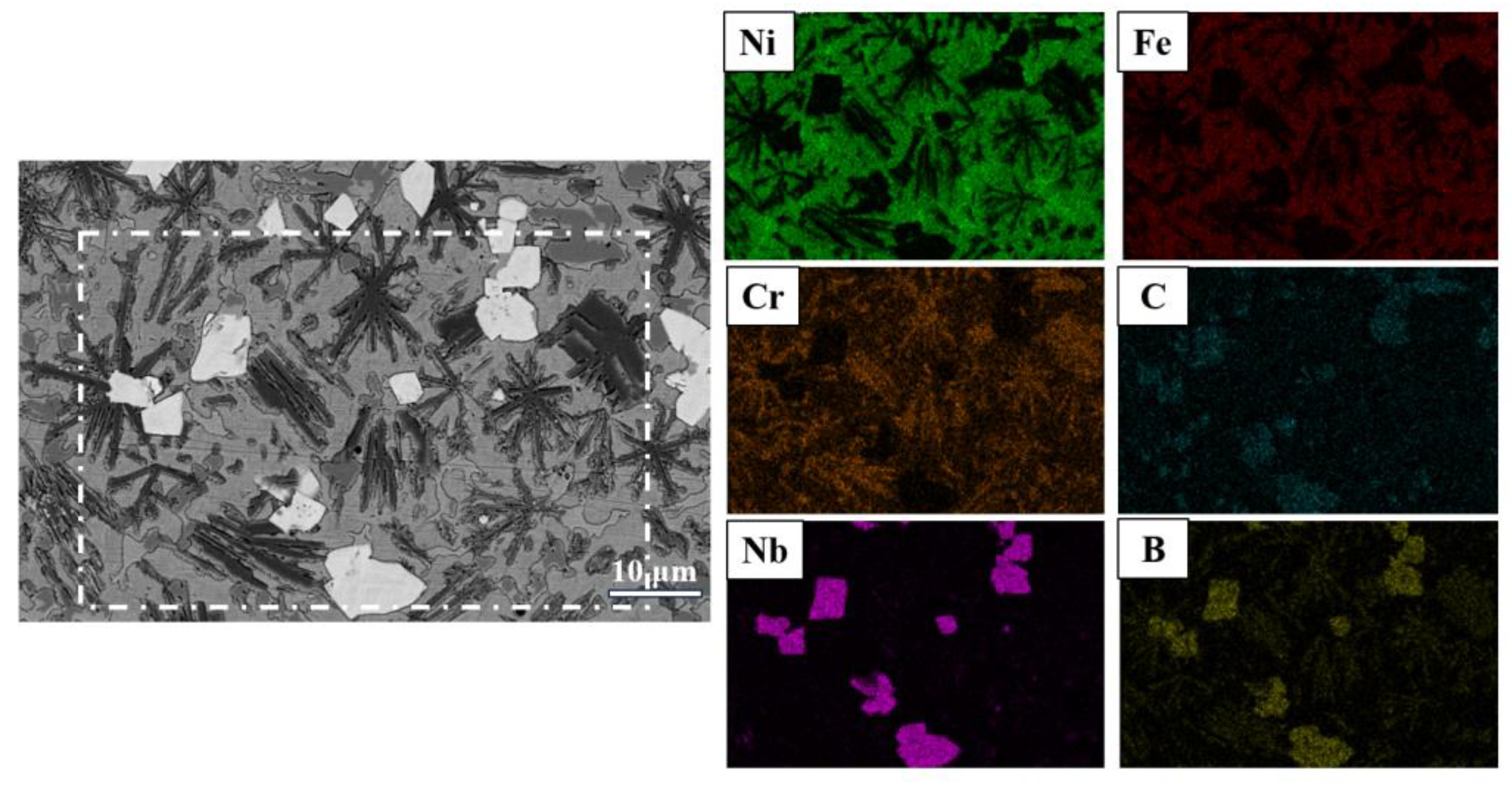
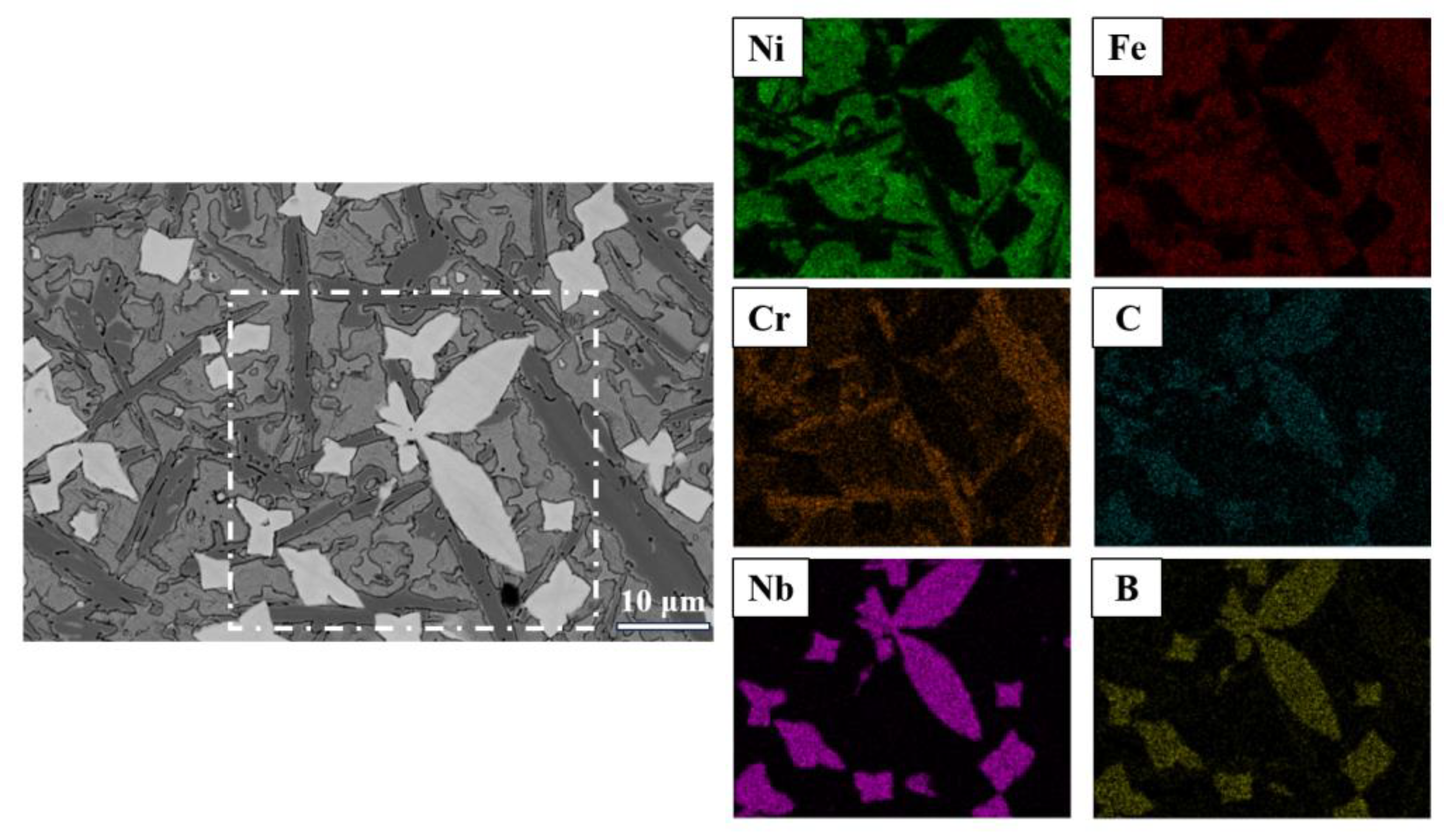
To further determine the types of each phase and the distribution of elements, the mapping of coatings 2#, 3# and 4# was performed using EDS in combination with SEM. As shown in Figure 6 and Figure 7, the matrices of coatings 2# and 3# are mainly Ni as well as a solid solution of Fe and Cr, which is known to be γ-Ni solid solution from XRD analysis. This is due to the rapid diffusion of Fe, Cr and Si from the melt pool into the high temperature austenite phase and solid solution strengthening under the irradiation of the laser beam. The main elements of the gray elongated phase are Cr and C, which are known as Cr23C6 from XRD analysis. The bright white bulk phase is mainly composed of Nb and C, which can be identified as NbC in combination with XRD analysis. In addition, a B solid solution can also be seen in the NbC phase, forming a Nb(C, B) solid solution [21]. The main elements of the black cluster-like phase are Cr and B. Combined with the XRD analysis, it is identified as a CrB phase. As shown in Figure 8, the black cluster-like phase largely disappeared in the coating 4#. It is presumed that with the increase in the amount of added FeNb65, a large number of Nb(C, B) hard ceramic phases are formed, which occupy the majority of B. Therefore, with the increase in NbC content, the CrB phase in the coating gradually disappears and the content of Cr23C6 gradually increases.

3.2. Microhardness Analysis

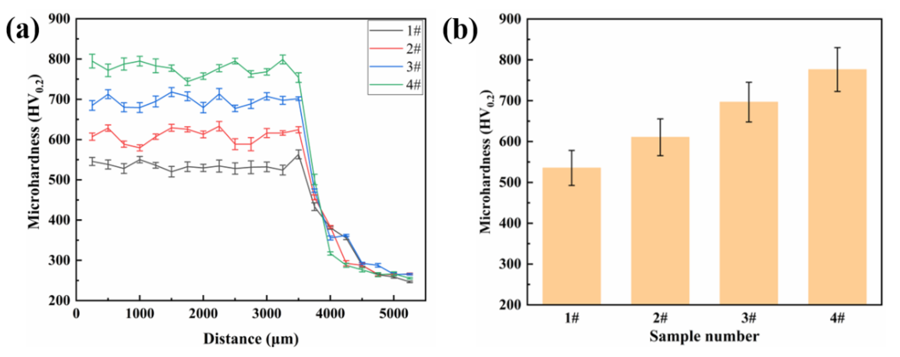
Microhardness is an important indicator of the mechanical properties of coatings, and the microhardness of the coating was tested at different depths along the direction perpendicular to the coating. The microhardness of the four groups of coatings at different depths and the average microhardness of the surface layer (3250 μm) are shown in Figure 9a,b, respectively. As shown in Figure 9a, the microhardness curves of the coatings show the same trend, with a relatively uniform microhardness in the superficial region. The heat-affected zone has a higher microhardness than the substrate due to it experiencing faster thermal cycling. As shown in Figure 9b, the microhardness of coating 1# is the lowest at about 535.3 HV0.2. The microhardnesses of coatings 2#, 3# and 4# increase sequentially, and the microhardness of coating 4# is the highest at 776.33 HV0.2, 45% higher compared to coating 1#. The enhancement of the coating hardness is mainly due to two reasons: One is the in situ synthesis of NbC with a hardness up to 2458.2 HV through ferro-niobium and Cr3C2, which effectively improves the microhardness of the coating. The second is the formation of Cr23C6 in the coating by the excess addition of Cr3C2, which also leads to a great improvement in the microhardness of the coating [22,23]. The relationship between the microhardness of the coating and the wear resistance is generally positively correlated, and the wear resistance of the coating can be effectively improved by enhancing the microhardness of the coating.

3.3. Wear Resistance Analysis

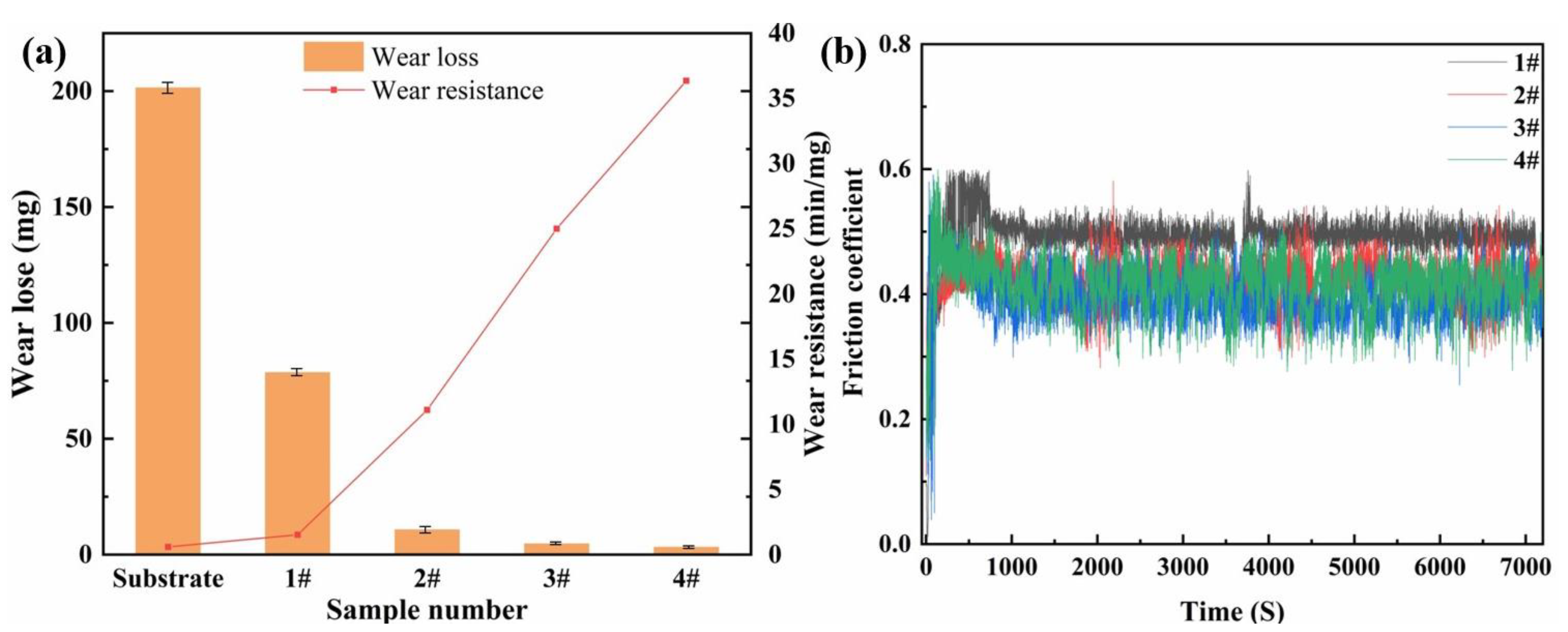
To study the wear resistance of the coating, the specimens were analyzed for wear resistance using a high-speed ring block friction wear tester. The wear loss and wear resistance of the coating after 2 h at 196 N are shown in Figure 10a. The wear loss of the base material Cr12MoV steel was as high as 201.5 mg, while the wear losses of the remaining four groups of coatings were 78.8 mg, 10.8 mg, 4.8 mg and 3.3 mg, respectively. The wear resistance of the coatings was characterized by the inverse of the average wear weight loss per unit time, and the wear resistances of the substrate and the four groups of coatings were 0.6 min/mg, 1.53 min/mg, 11.11 min/mg, 25 min/mg and 36.36 min/mg, respectively. The wear resistance of the Ni45 coating 1# increased by 155% compared to the substrate. The wear resistances of coatings 2#, 3# and 4# further improved due to the generation of high-hardness NbC and Cr23C6 phases. Among them, coating 4# showed the best wear resistance, which was increased by 606% compared to the base material. Figure 10b illustrates the friction coefficients of the four coatings during frictional wear. The friction coefficients of the coatings with the addition of a hard ceramic phase all decrease, but the friction coefficient of coating #2 fluctuates more, which may be due to the exfoliation of the hard phase with a larger particle size during the wear process. The improvement in the surface wear resistance of Cr12MoV steel is more significant compared with previous strengthening methods. Additionally, there are a wealth of very promising applications due to the reduced economic cost of surface strengthening of the material [24,25,26].
In order to analyze the wear morphology of the coating, the wear surface of the coating was observed using a laser confocal microscope. Three-dimensional images were constructed according to the wear depth, and the wear morphology and wear parameters of the coating surface are shown in Figure 11 and Table 3, respectively. Combining Figure 11 with Table 3, we can easily see that the width and depth of the wear marks and the cross-sectional area of coating 1# are the highest among the four groups of coatings. As the content of NbC increases, the width and depth of the abrasion marks and the cross-sectional area decrease significantly. Compared with coating 1#, the width and depth of wear marks and cross-sectional area of coating 4# decreased by 47.1%, 44.7% and 21.1%, respectively, and the wear resistance of the coating improved remarkably.
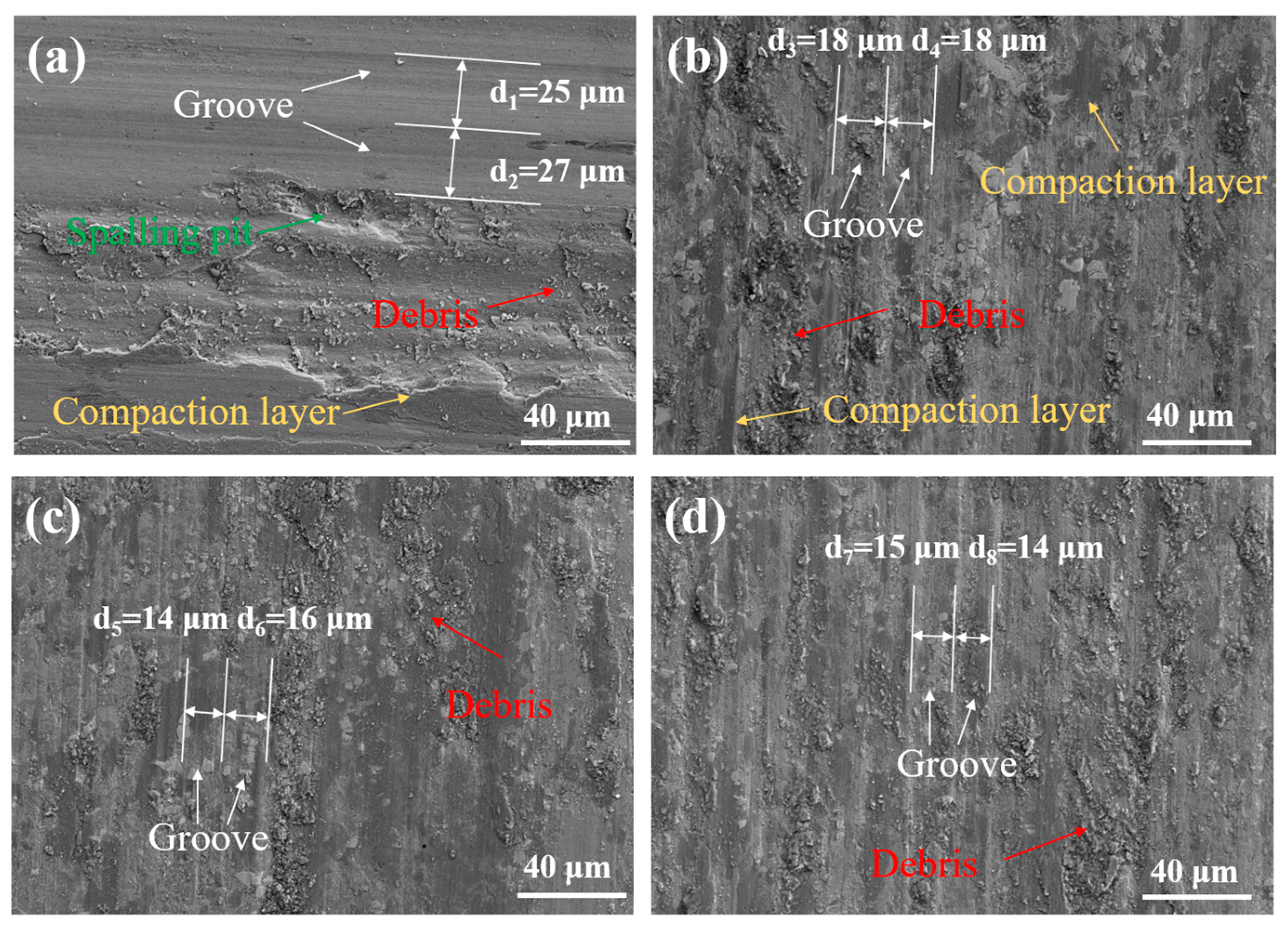
Figure 12 shows the wear morphology under a scanning electron microscope after frictional wear tests for the different compositions of coatings. From Figure 12a, it can be seen that there are plow grooves, a large amount of debris and a compaction layer on the surface of coating 1#, and the whole surface of the coating exhibits a wavy undulation. This is primarily because the hard ceramic phase of the coating flakes off during the wear of the coating and friction. During the relative movement of coating and grinding, ring scratches of different depths are left on the surface of the coating. Subsequently, some of the debris collects near the spalling pits and forms a compacted layer under a load of 196 N and tangential friction. In addition, because the Ni45 coating is relatively soft, the hard ceramic phase was more deeply pressed, forming wave-type undulations on the coating surface. Taken together, the wear mechanism of coating 1#’s surface is severe abrasive wear and intense adhesive wear. From Figure 12b, it can be seen that uniform plow grooves and debris also exist on the wear surface of coating 2#. The presence of hard ceramic phases can be observed in the grooves, and with the protection of these hard ceramic phases, the coating avoids further wear. Figure 12c,d shows that the wear mechanisms of coatings 3# and 4# are similar, with the coating surface uniformly distributed with grooves and a small amount of debris. It can be observed that more hard ceramic phases are formed inside the coating, which enhances the hardness of the coating and reduces the depth of the grooves. The wear mechanism of the coatings of these two samples is mainly abrasive wear. The width of the grooves on the surface of the four groups of coatings was measured, and the average widths were 26.0 μm, 18.0 μm, 15.0 μm and 14.5 μm, respectively. This measurement confirms that the formation of a hard ceramic phase improves the wear resistance of the coatings.
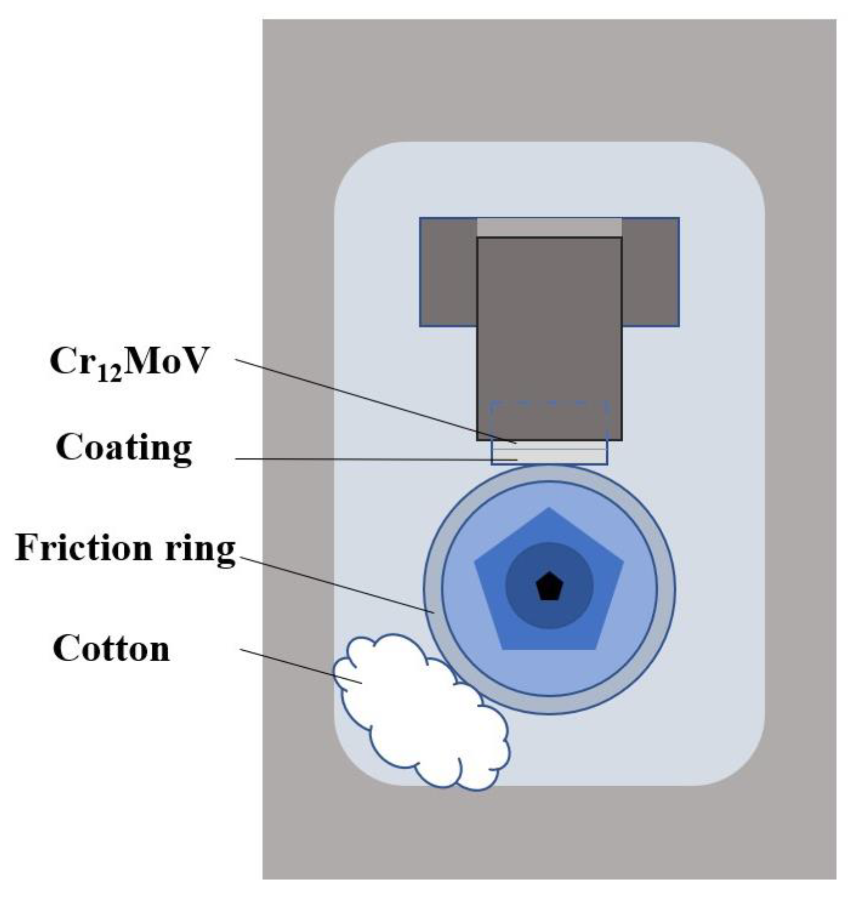
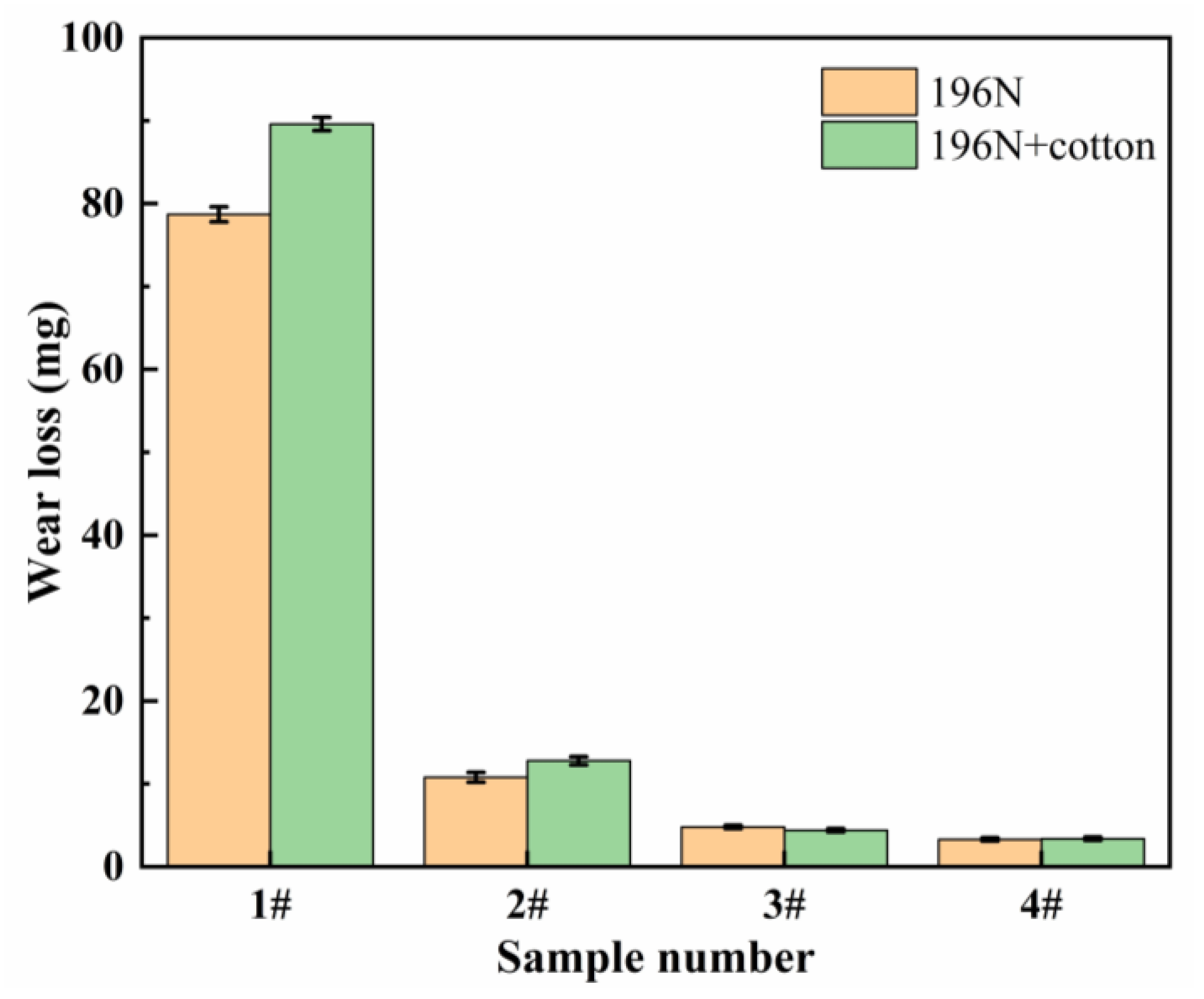
The wear weight loss of coatings 1# and 2# is high, and the exfoliated hard ceramic phase with the abraded debris is compacted under the extrusion of the grinding ring. It has been speculated that these compacted layers have some protective effect on the coating, thus improving the wear resistance of the coating [27,28,29,30]. To analyze the effect of these compacted layers on the wear resistance of the coating, the friction wear test was adjusted. The specific operation was to fix a ball of cotton in the inner cavity of the friction and wear tester, so that it was in close contact with the grinding ring. Thus, abrasive debris is removed from the surface of the grinding ring over time during the wear process to avoid the formation of a compacted layer. Before and after the test, the specimens were weighed using a balance with an accuracy of 0.1 mg, and the wear morphology of the coating was observed by scanning electron microscopy. By measuring the wear weight loss of the coating after modification of the high-speed ring block friction wear tester and observing the wear morphology of the coating, the effect of the compacted layer on the coating surface was studied. A schematic diagram of the modification of the experimental setup is shown in Figure 13. The specimen was rerun on the modified machine for a wear test with a test load of 196 N and a wear time of 2 h.
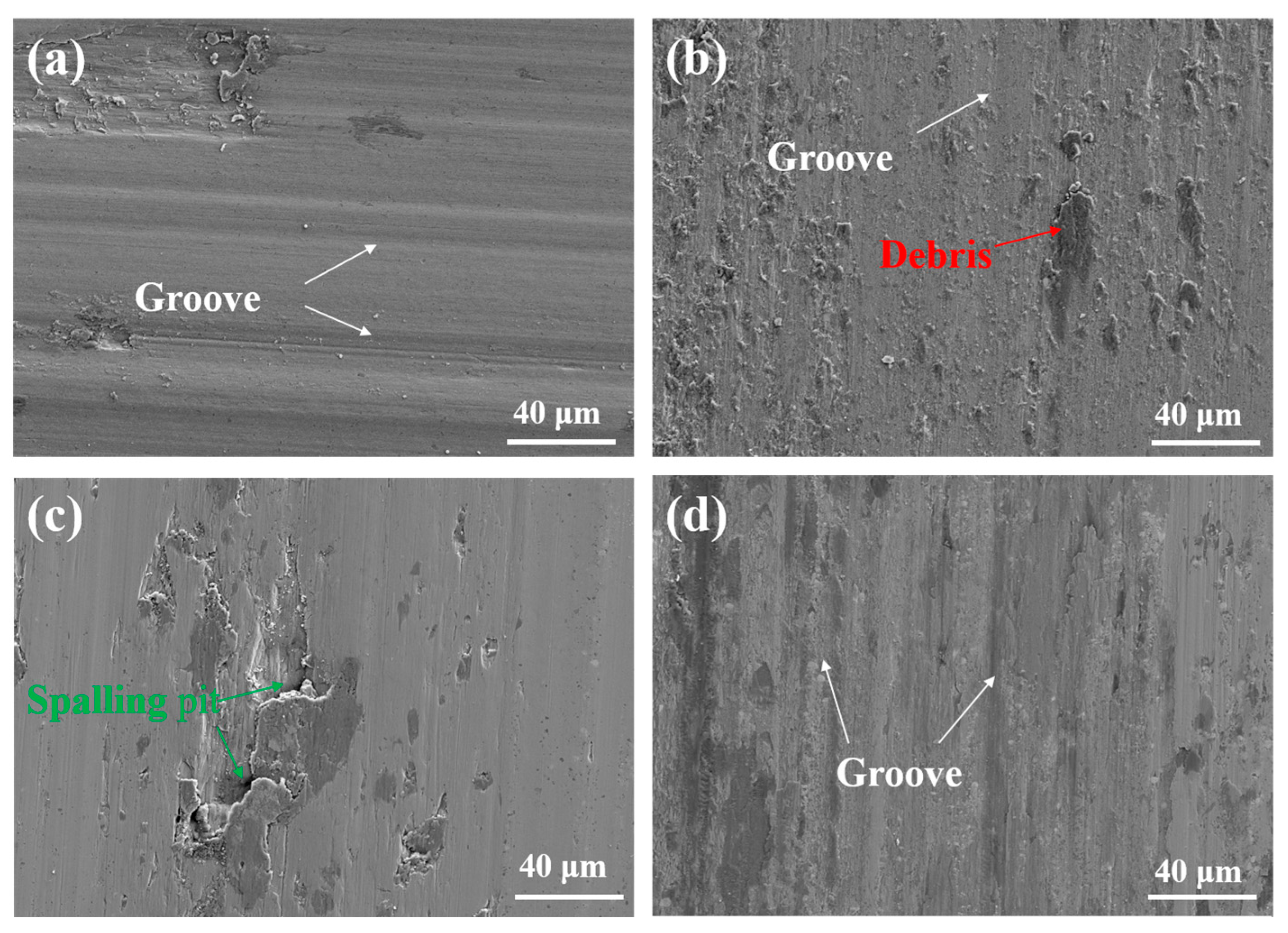
The wear morphology of the coating surface after the modification of the frictional wear experimental machine is shown in Figure 14. It can be seen that the addition of cotton on the grinding ring could effectively remove the debris on the surface of the coating, and the depth of the grooves on each coating surface was significantly reduced.
A comparison of the wear weight loss of the coatings before and after modification of the high-speed friction and wear tester is shown in the Figure 15. For coatings #1 and #2, which have a higher wear weight loss, the weight of wear increases. This is due to the removal of abrasive debris from the grinding ring, reducing the area of the compacted layer on the coating surface and thus reducing the protection of the coating surface. The decrease in the wear weight loss for coatings 3# and 4#, where abrasive wear dominates, is due to the removal of larger hard ceramic phase particles, which flake from the coating surface to avoid more wear on the coating surface from large hard ceramic phase particles.

4. Conclusions

In this study, laser-clad NbC-reinforced nickel-based composite coatings were successfully prepared using a mixture of Ni45, FeNb65 and Cr3C2 powders. The changes in microstructure, microhardness and wear resistance of the coatings were investigated in detail. The results show the significant potential of the coatings to be applied in the field of surface strengthening and repair. The findings of the study are summarized as follows:
1.
NbC was synthesized in situ from FeNb65 and Cr3C2, and elements such as Fe, Cr and Si diffused into the high temperature austenite phase to form a γ-Ni solid solution phase.
2.
With the increase in NbC content, the microhardness of the coating increases. The microhardness of coating 4# reached 776.3 HV0.2, a 45% increase in microhardness compared to coating 1#. This is attributed to the uniform distribution of the NbC phase and Cr23C6 in the coating.
3.
The wear resistance of the coatings increased significantly with the increase in NbC content. Coating 4# with 25 wt.% FeNb65 + Cr3C2 showed the best wear resistance of 36.36 min/mg, an improvement of 606.0% in abrasion resistance compared to the base material and 227.6% compared to coating 1#.
4.
The compacted layer formed by abrasive extrusion protects the coating surface when subjected to wear, reducing the wear of the coating.

Author Contributions

Conceptualization, H.F. and Y.L.; methodology, K.W.; resources, H.F.; data curation, Y.L.; writing—original draft preparation, Y.L.; writing—review and editing, H.F. and Y.L.; visualization, B.Z. and J.Z.; funding acquisition, H.F. All authors have read and agreed to the published version of the manuscript.

Funding

This research was funded by R&D Program of Beijing Municipal Education Commission grant number KZ202210005004.

Data Availability Statement

All data is contained within the article.

Conflicts of Interest

The authors declare no conflict of interest.

References

  1. Jiang, L.; Cui, X.; Jin, G.; Tian, Z.; Wen, X.; Tian, H.; Liu, E. Design and characterization of a novel Cu2.3Al1.3Ni1.7SnCr0.3 multi-principal element alloy coating on magnesium alloy by laser cladding. J. Mater. Sci. Technol. 2023, 152, 220–236. [Google Scholar] [CrossRef]
  2. Zhu, Z.-X.; Liu, X.-B.; Liu, Y.-F.; Zhang, S.-Y.; Meng, Y.; Zhou, H.-B. Effects of Cu/Si on the microstructure and tribological properties of FeCoCrNi high entropy alloy coating by laser cladding. Wear 2023, 512, 204533. [Google Scholar] [CrossRef]
  3. Wu, S.; Liu, Z.; Gong, Y.; Liang, X.; Wu, Y.; Zhao, X. Analysis of the sequentially coupled thermal–mechanical and cladding geometry of a Ni60A-25%WC laser cladding composite coating. Opt. Laser Technol. 2023, 167, 109595. [Google Scholar] [CrossRef]
  4. Budde, L.; Biester, K.; Coors, T.; Faqiri, M.Y.; Lammers, M.; Hermsdorf, J.; Hassel, T.; Pape, F.; Overmeyer, L. Influence of shielding gas coverage during laser hot-wire cladding with high carbon steel. Int. J. Adv. Manuf. Technol. 2023, 127, 3195–3207. [Google Scholar] [CrossRef]
  5. Bhatnagar, S.; Mullick, S. A study on the influence of reinforcement particle size in laser cladding of TiC/Inconel 625 metal matrix composite. Opt. Laser Technol. 2023, 161, 109115. [Google Scholar] [CrossRef]
  6. Thompson, S.M.; Bian, L.K.; Shamsaei, N.; Yadollahi, A. An overview of Direct Laser Deposition for additive manufac-turing; Part I: Transport phenomena, modeling and diagnostics. Addit. Manuf. 2015, 8, 36–62. [Google Scholar]
  7. Szost, B.A.; Terzi, S.; Martina, F.; Boisselier, D.; Prytuliak, A.; Pirling, T.; Hofmann, M.; Jarvis, D.J. A comparative study of additive manufacturing techniques: Residual stress and microstructural analysis of CLAD and WAAM printed Ti–6Al–4V components. Mater. Des. 2016, 89, 559–567. [Google Scholar] [CrossRef] [Green Version]
  8. Sun, D.; Zhu, L.; Cai, Y.; Yan, Y.; Ge, F.; Shan, M.; Tian, Y.; Han, J.; Jiang, Z. Tribology comparison of laser-cladded CrMnFeCoNi coatings reinforced by three types of ceramic (TiC/NbC/B4C). Surf. Coat. Technol. 2022, 450, 129013. [Google Scholar] [CrossRef]
  9. Paul, C.P.; Gandhi, B.K.; Bhargava, P.; Dwivedi, D.K.; Kukreja, L.M. Cobalt-Free Laser Cladding on AISI Type 316L Stainless Steel for Improved Cavitation and Slurry Erosion Wear Behavior. J. Mater. Eng. Perform. 2014, 23, 4463–4471. [Google Scholar] [CrossRef]
  10. Apolinário, L.H.R.; Torres, E.A.; Araújo, H.R.; Vicente, A.d.A.; Santos, T.F.d.A. Effect of laser cladding parameters in NbC reinforced 316L austenitic stainless steel composite depositions on a mild steel. Int. J. Adv. Manuf. Technol. 2022, 122, 3095–3113. [Google Scholar] [CrossRef]
  11. Jie, G.; Qingchao, M.; Yan, S.; Kangning, W.; Qiang, S.; Canming, W. Effect of Nb content on microstructure and corrosion resistance of Inconel 625 coating formed by laser cladding. Surf. Coat. Technol. 2023, 458, 129311. [Google Scholar] [CrossRef]
  12. Wang, J.; Zhang, Q.; Shen, W.; Liang, Z.; Chang, C.; Yang, L.; Li, J.; Huang, F. Failure Analysis of a Chromium Plating Layer on a Piston Rod Surface and the Study of Ni-Based Composite Coating with Nb Addition by Laser Cladding. Metals 2022, 12, 1194. [Google Scholar] [CrossRef]
  13. Pizzatto, A.; Teixeira, M.F.; Rabelo, A.; Falcade, T.; Scheid, A. Microstructure and Wear Behavior of NbC-Reinforced Ni-Based Alloy Composite Coatings by Laser Cladding. Mater. Res. Ibero Am. J. Mater. 2021, 24, e20200447. [Google Scholar] [CrossRef]
  14. Lian, G.F.; Yue, K.; Zeng, J.Y.; Feng, M.Y.; Lan, R.Q.; Kong, L.H. Microstructures and Properties of NbC-Reinforced Ni-Based Coatings Synthesized In Situ by Ultrasonic Vibration-Assisted Laser Cladding. Materials 2023, 16, 1704. [Google Scholar] [CrossRef] [PubMed]
  15. Shi, B.; Huang, S.; Zhu, P.; Xu, C.; Zhang, T. Microstructure and Wear Behavior of In-Situ NbC Reinforced Composite Coatings. Materials 2020, 13, 3459. [Google Scholar] [CrossRef] [PubMed]
  16. Li, Q.; Lei, Y.; Fu, H. Laser cladding in-situ NbC particle reinforced Fe-based composite coatings with rare earth oxide addition. Surf. Coat. Technol. 2014, 239, 102–107. [Google Scholar] [CrossRef]
  17. Dong, G.; Yan, B.; Deng, Q.; Yu, T. Microstructure and wear resistance of in situ NbC particles reinforced Ni-based alloy composite coating by laser cladding. J. Wuhan Univ. Technol. Sci. Ed. 2012, 27, 231–237. [Google Scholar] [CrossRef]
  18. Wang, K.; Du, D.; Liu, G.; Chang, B.; Ju, J.; Sun, S.; Fu, H. Microstructure and property of laser clad Fe-based composite layer containing Nb and B4C powders. J. Alloys Compd. 2019, 802, 373–384. [Google Scholar] [CrossRef]
  19. Chen, L.; Yu, T.; Xu, P.; Zhang, B. In-situ NbC reinforced Fe-based coating by laser cladding: Simulation and experiment. Surf. Coat. Technol. 2021, 412, 127027. [Google Scholar] [CrossRef]
  20. Sun, S.; Fu, H.; Ping, X.; Lin, J.; Lei, Y.; Wu, W.; Zhou, J. Reinforcing behavior and microstructure evolution of NbC in laser cladded Ni45 coating. Appl. Surf. Sci. 2018, 455, 160–170. [Google Scholar] [CrossRef]
  21. Chen, Z.; Yan, H.; Zhang, P.; Yu, Z.; Lu, Q.; Guo, J. Microstructural evolution and wear behaviors of laser-clad Stellite 6/NbC/h-BN self-lubricating coatings. Surf. Coat. Technol. 2019, 372, 218–228. [Google Scholar] [CrossRef]
  22. Jellad, A.; Labdi, S.; Benameur, T. On the hardness and the inherent ductility of chromium carbide nanostructured coatings prepared by RF sputtering. J. Alloys Compd. 2009, 483, 464–467. [Google Scholar] [CrossRef]
  23. Yu, T.; Tang, H. Microstructure and high-temperature wear behavior of laser clad TaC-reinforced Ni-Al-Cr coating. Appl. Surf. Sci. 2022, 592, 153263. [Google Scholar] [CrossRef]
  24. Huang, L.; Zhou, J.; Xu, J.; Huo, K.; He, W.; Meng, X.; Huang, S. Microstructure and wear resistance of electromagnetic field assisted multi-layer laser clad Fe901 coating. Surf. Coat. Technol. 2020, 395, 125876. [Google Scholar] [CrossRef]
  25. Yan, H.; Chen, Z.F.; Zhao, J.; Zhang, P.L.; Yu, Z.S.; Lu, Q.H. Enhancing tribological properties of WS2/NbC/Co-based self-lubricating coating via laser texturing and laser cladding two-step process. J. Mater. Res. Technol. 2020, 9, 9907–9919. [Google Scholar] [CrossRef]
  26. Gao, Y.; Tong, Y.; Guohui, L.; Lu, P.; Zhang, D. Microstructure and Mechanical Properties of Ni-Based Alloy Composite Coating on Cr12MoV by Laser Cladding. Coatings 2022, 12, 1632. [Google Scholar] [CrossRef]
  27. Wu, J.Q.; Li, Z.; Luo, Y.; Li, Y.; Gao, Z.L.; Zhao, Y.B.; Wu, C.W.; Liao, Y.X.; Jin, M. The effects of double ceramic particles (B4C-SiC) on the performance, microstructure, and friction-wear mechanisms of copper-based PM. Tribol. Int. 2022, 175, 107865. [Google Scholar] [CrossRef]
  28. Yin, H.G.; Li, J.H.; Zhao, L.W.; Yao, F. Simulation of in-situ preheating of ni-based multi-layer and multi-pass coatings on H13 steel. J. Mech. Sci. Technol. 2022, 36, 4671–4680. [Google Scholar] [CrossRef]
  29. Zhu, Y.; Song, X.; Liu, M.; Jia, W.; Yin, Z.; Wang, Q.; Zhang, Y.; Jiang, D.; Song, Q.; Cui, H. Improved wear resistance of TiAl composite coatings through NbC@(Ti,Nb)2AlC core-shell structure and nanoscale precipitation strengthening. Vacuum 2023, 213, 112091. [Google Scholar] [CrossRef]
  30. Liu, X.; Bi, J.; Meng, Z.; Li, R.; Li, Y.; Zhang, T. Tribological behaviors of high-hardness Co-based amorphous coatings fabricated by laser cladding. Tribol. Int. 2021, 162, 107142. [Google Scholar] [CrossRef]
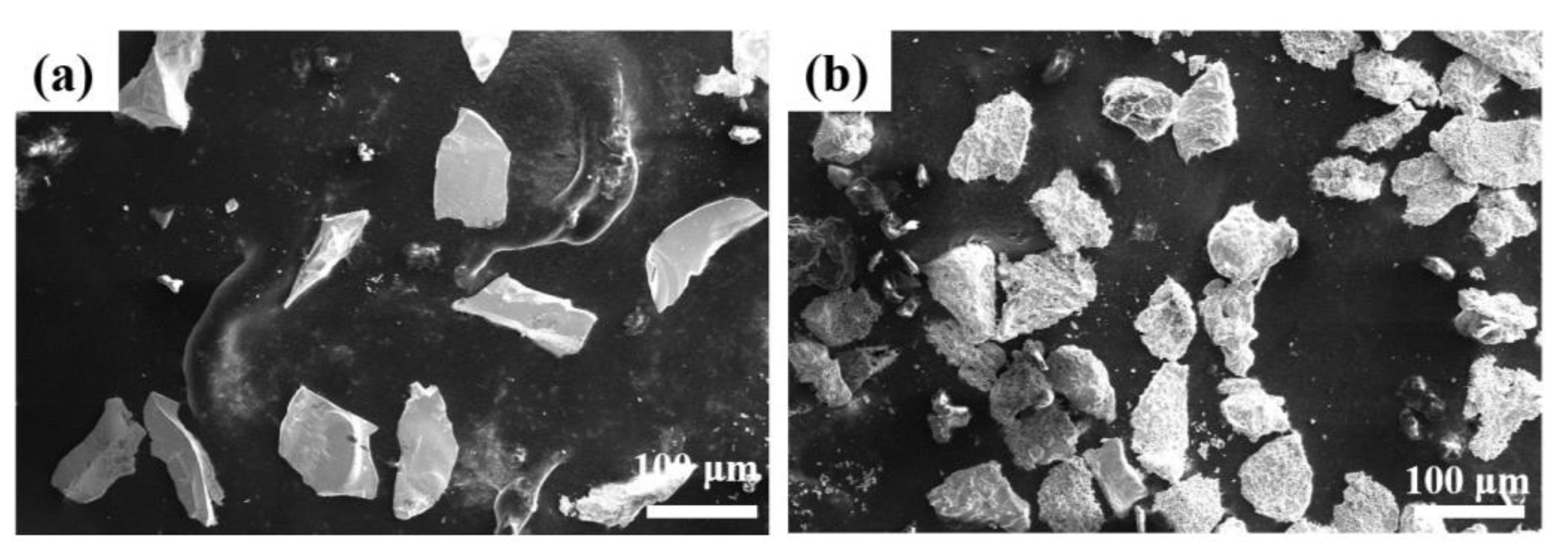
Figure 1. Morphology of Cr3C2 (a) and FeNb65 (b) powders selected for the in situ synthesis of NbC.
Lubricants 11 00316 g001
Figure 2. A diagram of the laser cladding experimental setup.
Lubricants 11 00316 g002
Figure 3. XRD patterns of nickel-based composite coatings with different compositions.
Lubricants 11 00316 g003
Figure 4. Microstructures of the coating at low magnification under SEM: (a) 1#; (b) 2#; (c) 3#; (d) 4#.
Lubricants 11 00316 g004
Figure 5. Microstructures of the coating at high power under SEM: (a) 1#; (b) 2#; (c) 3#; (d) 4#.
Lubricants 11 00316 g005
Figure 6. SEM—element distribution mapping of coating 2#.
Lubricants 11 00316 g006
Figure 7. SEM—element distribution mapping of coating 3#.
Lubricants 11 00316 g007
Figure 8. SEM—element distribution mapping of coating 4#.
Lubricants 11 00316 g008
Figure 9. Microhardness of the coatings: (a) microhardness at different depths; (b) average microhardness.
Lubricants 11 00316 g009
Figure 10. Wear characteristics of coatings: (a) wear weight loss and wear resistance; (b) friction coefficients.
Lubricants 11 00316 g010
Figure 11. Three-dimensional diagram of the wear pattern on the surface of coatings (a) 1#; (b) 2#; (c) 3#; (d) 4#.
Lubricants 11 00316 g011
Figure 12. Morphology of the worn surface of coating (a) 1#; (b) 2#; (c) 3#; (d) 4#.
Lubricants 11 00316 g012
Figure 13. Schematic diagram of the adjusted friction and wear experimental setup.
Lubricants 11 00316 g013
Figure 14. The wear morphology of the coating surface after adding cotton: (a) 1#; (b) 2#; (c) 3#; (d) 4#.
Lubricants 11 00316 g014
Figure 15. Comparison of wear weight loss of coatings before and after modification of the friction and wear tester.
Lubricants 11 00316 g015
Table 1. Composition of Cr12MoV and Ni45 (wt.%).
NiCrBSiFeCMnPVMoSCu
Cr12MoV0.1212.30-0.27Bal.1.440.210.020.270.550.010.13
Ni45Bal.10.021.893.055.300.33------
Table 2. Coating numbers and composition (wt.%).
Ni45FeNb65 + Cr3C2
1#1000
2#8515
3#8020
4#7525
Table 3. Width, depth and cross-sectional area of the wear profile of coating surfaces.
1#2#3#4#
Width (μm)6489.04033.13061.83059.3
Depth (μm)26.522.621.411.9
Area (μm2)86,122.045,636.632,808.318,129.1
Disclaimer/Publisher’s Note: The statements, opinions and data contained in all publications are solely those of the individual author(s) and contributor(s) and not of MDPI and/or the editor(s). MDPI and/or the editor(s) disclaim responsibility for any injury to people or property resulting from any ideas, methods, instructions or products referred to in the content.