Numerical Analysis of Double Riveted Lap Joints


Abstract
:1. Introduction
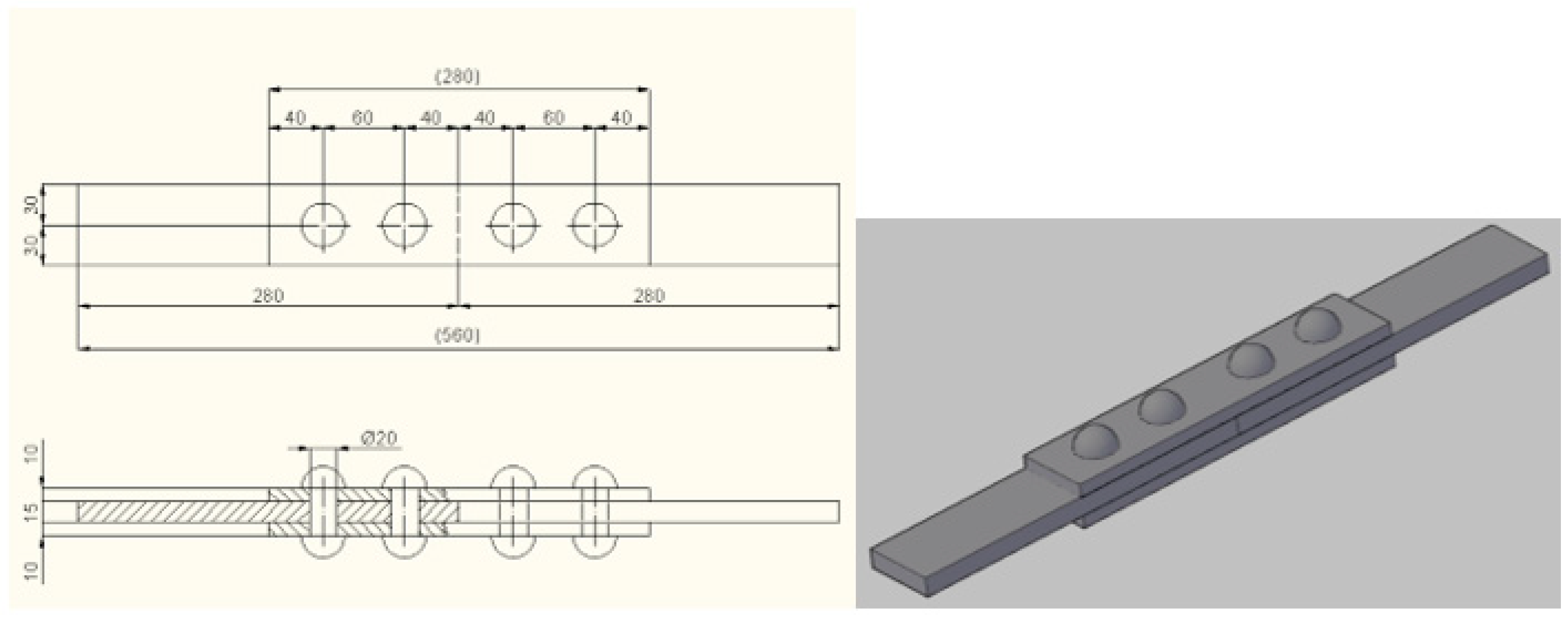
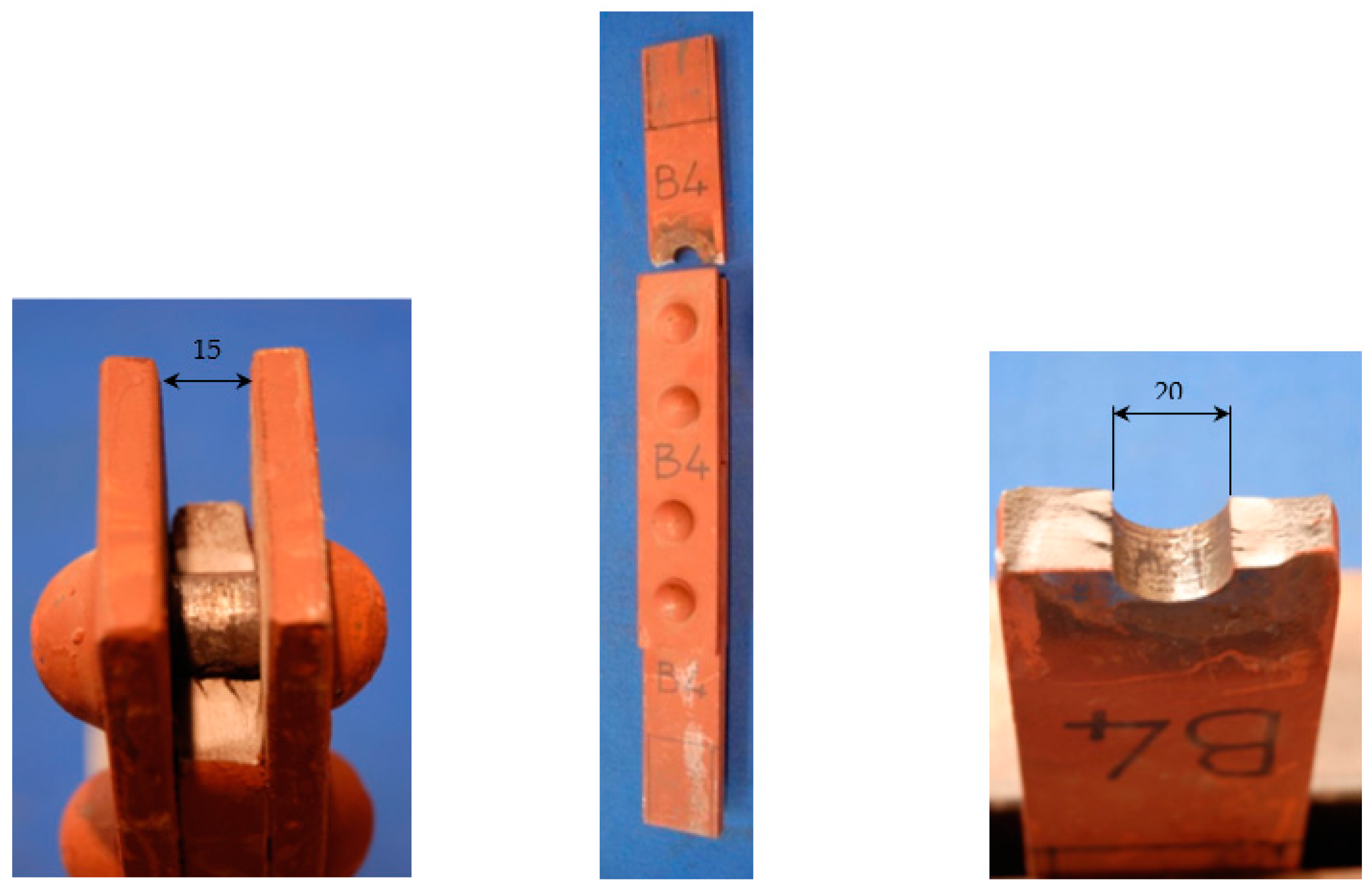
2. Geometry of the Riveted Joints and Fatigue Test
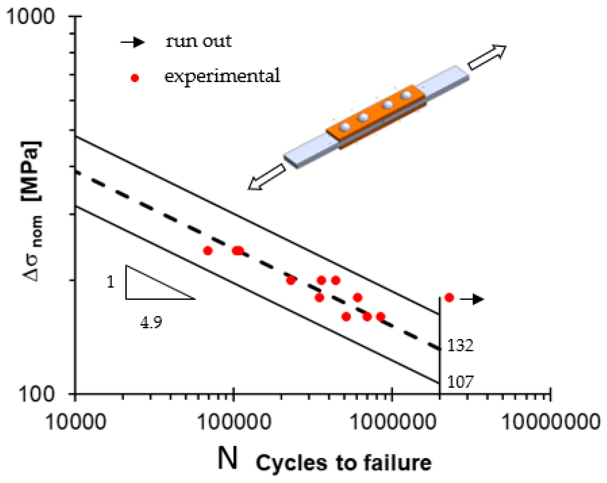
3. Fatigue Life of the Joints
4. Numerical Analysis
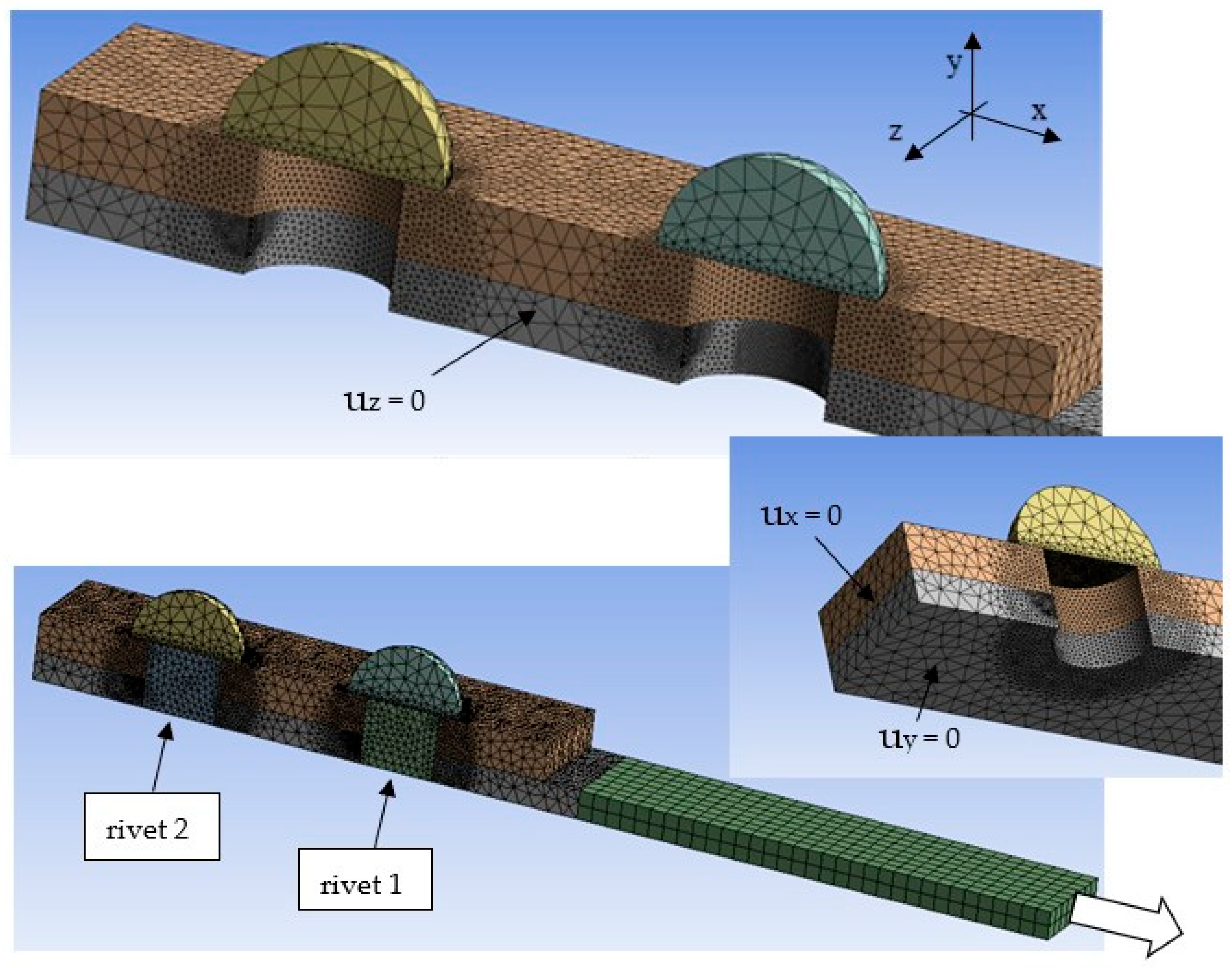
4.1. The FE Model
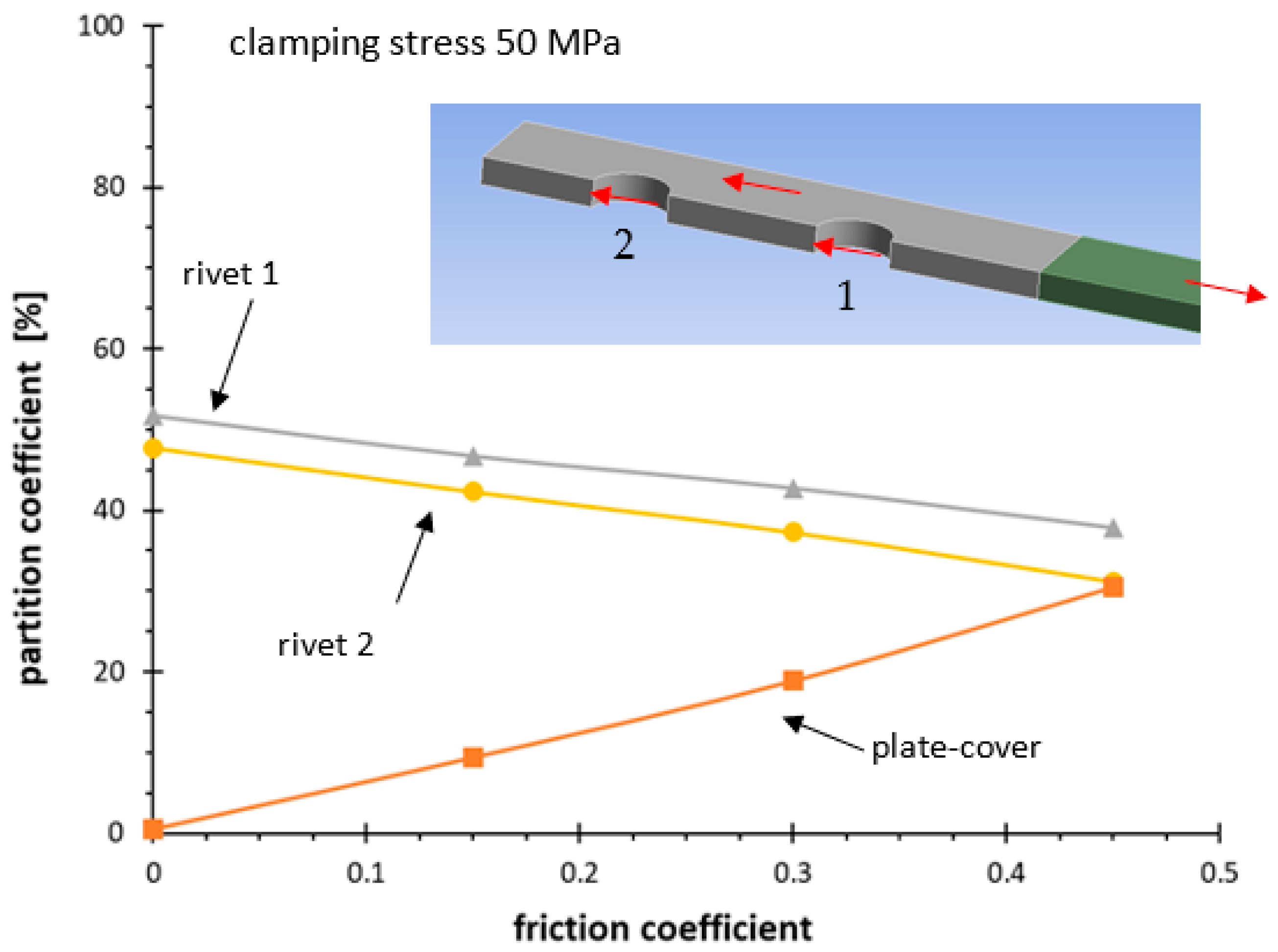
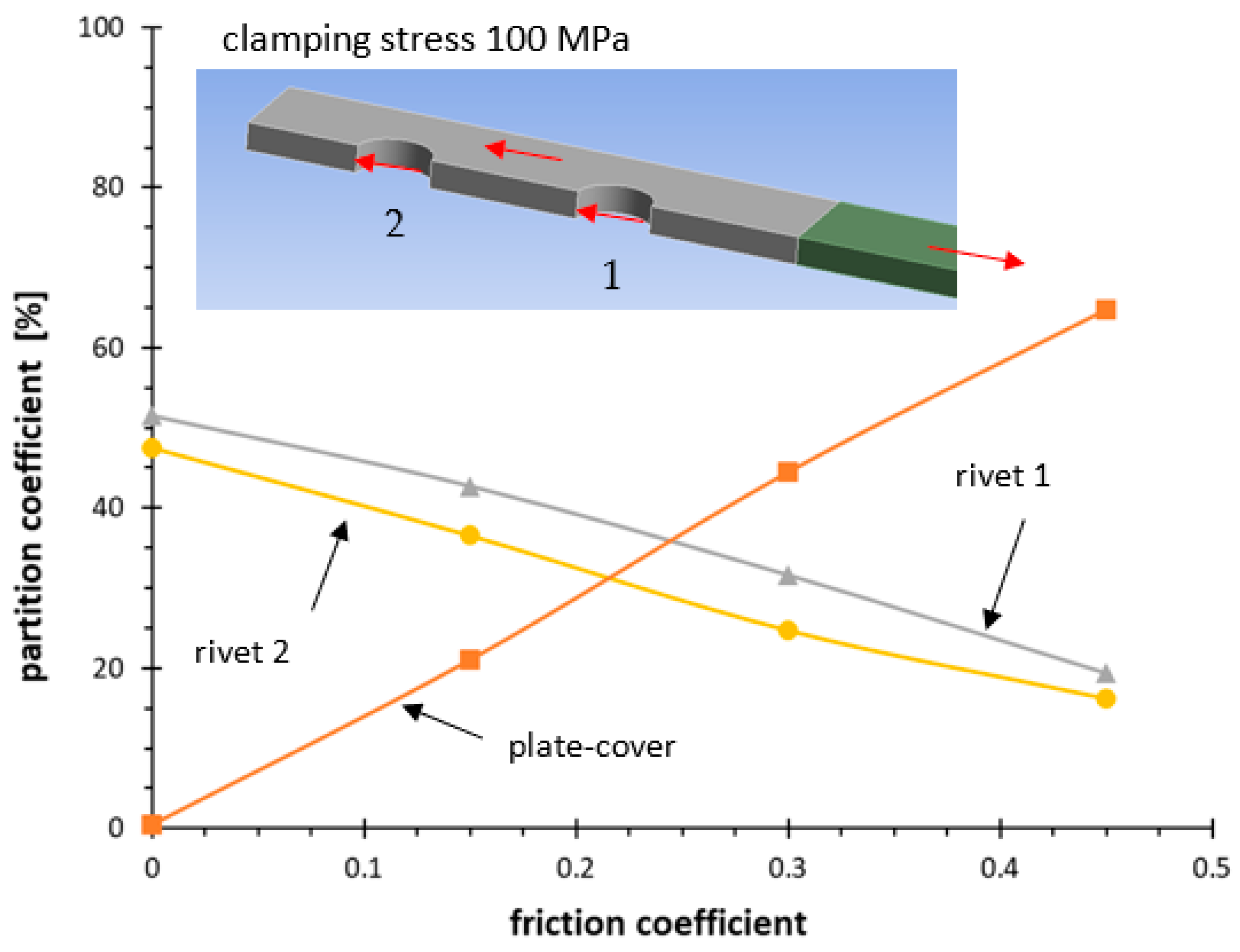
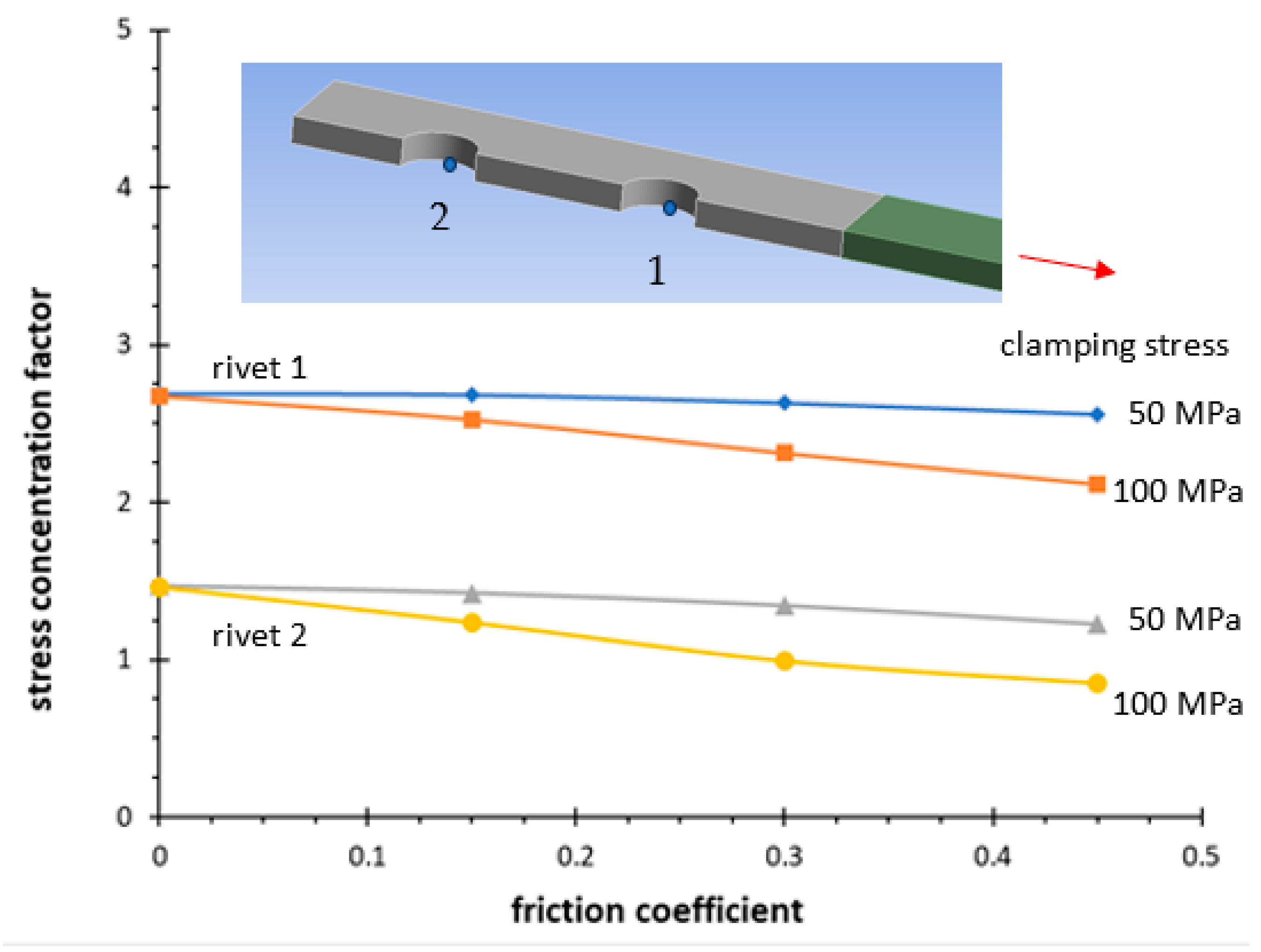
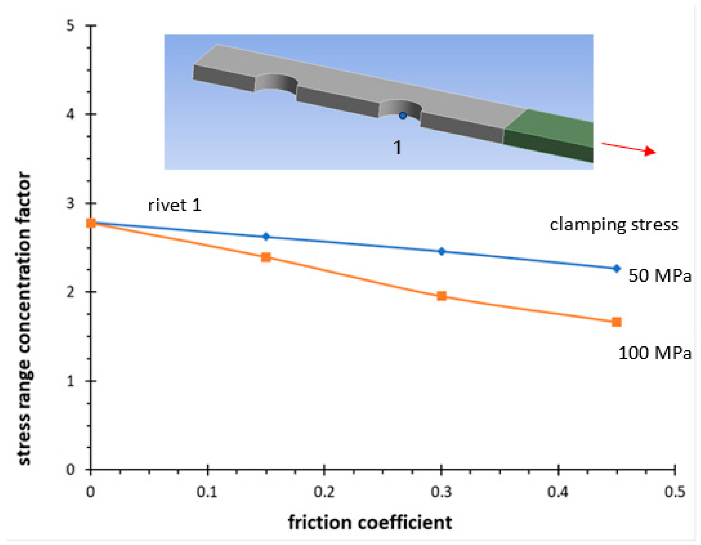
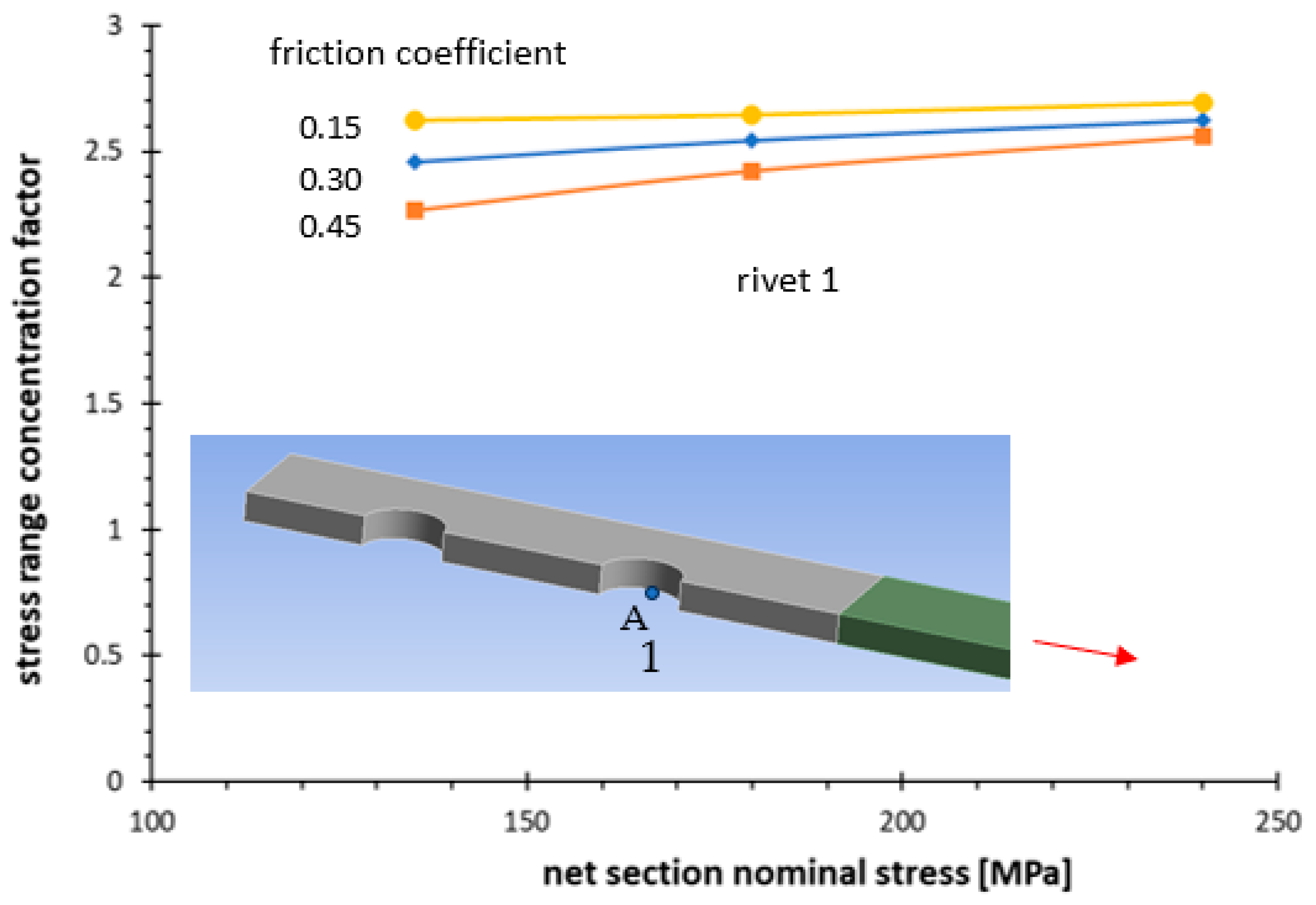
4.2. Results
5. Conclusions
Funding
Data Availability Statement
Conflicts of Interest
Nomenclature
| E | elastic modulus |
| k | slope of the Wöhler curve |
| N | cycles to failure |
| ν | Poisson’s ratio |
| σnom | nominal stress |
| σY | yield stress |
| Δ | range |
| σ | stress component |
| Tσ | scatter index |
| u | displacement |
References
- Brühwiler, E.; Smith, I.F.C.; Hirt, M.A. Fatigue and fracture of riveted bridge members. ASCE J. Struct. Eng. 1990, 116, 199–214. [Google Scholar] [CrossRef]
- Kulak, G.L. Fatigue strength of riveted connections. Stahlbau 1996, 65, 445–451. [Google Scholar]
- Bassetti, A.; Liechti, P.; Nussbaumer, A. Fatigue Design and Reliability; ESIS Publication 23; Marquis, G., Solin, J., Eds.; Elsevier: Amsterdam, The Netherlands, 1999; pp. 207–218. [Google Scholar]
- DiBattista, J.D.; Adamson, E.J.; Kulak, G.L. Fatigue strength of riveted connections. ASCE. J. Struct. Eng. 1998, 124, 792–797. [Google Scholar] [CrossRef]
- American Railway Engineering Association (AREA). Steel Structures; Chapter 15, Manual for Railway Engineering; American Railway Engineering Association: Lanham, MD, USA, 1996. [Google Scholar]
- American Association of State Highway and Transportation Officials. ASHTO LRFD Bridge Design Specifications. S/Units, 1st ed.; American Association of State Highway and Transportation Officials: Washington, DC, USA, 1994. [Google Scholar]
- Design of Steel Structures Part 1, General Rules for Buildings; Eurocode No. 3; 1993.
- Taras, A.; Greiner, R. Development and Application of a Fatigue Class Catalogue for Riveted Bridge Components. Struct. Eng. Int. 2010, 20, 91–103. [Google Scholar] [CrossRef]
- Kühn, B.; Lukic, B.; Nussbaumer, A.; Günther, H.P.; Helmerich, R.; Herion, S.; Kolstein, M.H.; Walbridge, S.; Androic, B.; Dijkstra, O.; et al. Assessment of Existing Steel Structures: Recommendations for Estimation of Remaining Fatigue Life, 1st ed.; JRC Scientific and Technical Reports, Joint Report Prepared under the JRC—ECCS Cooperation Agreement for the Evolution of Eurocode 3; Joint Research Center: Karlsruhe, Germany, 2008. [Google Scholar]
- Pedrosa, B.; Correia, J.A.; Rebelo, C.; Lesiuk, G.; De Jesus, A.M.; Fernandes, A.A.; Duda, M.; Calçada, R.; Veljkovic, M. Fatigue resistance curves for single and double shear riveted joints from old Portuguese metallic bridges. Eng. Fail. Anal. 2019, 96, 255–273. [Google Scholar] [CrossRef]
- Reemsnyder, H.S. Fatigue life extension of riveted connections. J. Struct. Div. ASCE 1975, 101, 2591–2607. [Google Scholar] [CrossRef]
- DiBattista, J.D.; Adamson, D.E.J.; Kulak, G.L. Evaluation of remaining fatigue life for riveted truss bridges. Can. J. Civ. Eng. 1998, 25, 678–691. [Google Scholar] [CrossRef]
- Pipinato, A.; Molinari, M.; Pellegrino, C.; Bursi, O.S.; Modena, C. Fatigue tests on riveted steel elements taken from a railway bridge. Struct. Infrastruct. Eng. 2011, 7, 907–920. [Google Scholar] [CrossRef]
- Livieri, P.; Lazzarin, P.; Mutignani, F.; Tisalvi, M. Fatigue tests on riveted connections. In Proceedings of the 9th Nordic Steel Construction Conference, Helsinki, Finland, 18–20 June 2001; pp. 599–606. [Google Scholar]
- de Jesus, A.M.P.; da Silva, A.L.L.; Correia, J.A.F.O. Fatigue of riveted and bolted joints made of puddle iron—A numerical approach. J. Constr. Steel Res. 2014, 102, 164–177. [Google Scholar] [CrossRef]
- Maljaars, J.; Leonetti, D.; Maas, C. Fatigue life prediction of hot riveted double covered butt joints. Int. J. Fatigue 2019, 124, 99–112. [Google Scholar] [CrossRef]
- Manson, S.S. Fatigue: A complex subject—Some simple approximations. Exp. Mech. 1965, 5, 193–226. [Google Scholar] [CrossRef]
- Morrow, J. Fatigue Properties of Metals. In Fatigue Design Handbook; Graham, J.A., Millan, J.F., Appl, F.J., Eds.; SAE: Warrendale, PA, USA, 1968; pp. 21–29. [Google Scholar]
- Ramberg, W.; Osgood, W.R. Description of Stress-Strain Curves by Three Parameters; Technical Note 902; NASA: Washington, DC, USA, 1943.
- Taylor, D. The theory of critical distances. Eng. Fract. Mech. 2007, 75, 1696–1705. [Google Scholar] [CrossRef]
- Susmel, L.; Taylor, D. The theory of critical distances to estimate lifetime of notched components subjected to variable amplitude uniaxial fatigue loading. Int. J. Fatigue 2011, 33, 900–911. [Google Scholar] [CrossRef]
- Lazzarin, P.; Zambardi, R. A finite-volume-energy based approach to predict the static and fatigue behavior of components with sharp V-shaped notches. Int. J. Fract. 2001, 112, 275–298. [Google Scholar] [CrossRef]
- Lazzarin, P.; Berto, F. Some expressions for the strain energy in a finite volume surrounding the root of blunt V-notches. Int. J. Fract. 2005, 135, 161–185. [Google Scholar] [CrossRef]
- Livieri, P.; Lazzarin, P. Fatigue strength of steel and aluminium welded joints based on generalised stress intensity factors and local strain energy values. Int. J. Fract. 2005, 133, 247–276. [Google Scholar] [CrossRef]
- Berto, F.; Lazzarin, P.; Yates, J.R. Multiaxial fatigue of V-notched steel specimens: A non-conventional application of the local energy method. Fatigue Fract. Eng. Mater. Struct. 2021, 34, 921–943. [Google Scholar] [CrossRef]
- Livieri, P.; Tovo, R. Fatigue strength of aluminium welded joints by a non-local approach. Int. J. Fatigue 2021, 143, 106000. [Google Scholar] [CrossRef]
- Livieri, P.; Tovo, R. Actual weld profile fatigue performance by digital prototyping of defected and un-defected joints. Fatigue Fract. Eng. Mater. Struct. 2022, 45, 3436–3446. [Google Scholar] [CrossRef]
- Skorupa, M.; Machniewicz, T.; Skorupa, A.; Korbel, A. Effect of load transfer by friction on the fatigue behaviour of riveted lap joints. Int. J. Fatigue 2016, 90, 1–11. [Google Scholar] [CrossRef]
- Vivio, F. A new theoretical approach for structural modelling of riveted and spot welded multi-spot structures. Int. J. Solids Struct. 2009, 46, 4006–4024. [Google Scholar] [CrossRef]
- Di Cicco, F.; Fanelli, P.; Vivio, F. Fatigue reliability evaluation of riveted lap joints using a new rivet element and DFR. Int. J. Fatigue 2017, 101, 430–438. [Google Scholar] [CrossRef]
- Jia, D.; Zhang, Q.; Xiong, L.; Li, J.; Bu, Y.; Bao, Y. A unified evaluation method for fatigue resistance of riveted joints based on structural stress approach. Int. J. Fatigue 2022, 160, 106871. [Google Scholar] [CrossRef]
- EN 10025; Hot Rolled Products of Non-Alloy Structural Steels—Technical Delivery Conditions. 1995.


| Series | Δσnom,50% N = 2 × 10⁶ | k | Tσ |
|---|---|---|---|
| B | 131.7 | 4.9 | 1.53 |
| E [MPa] | 206,000 |
| ν | 0.3 |
| σY [MPa] | 355 |
| Friction coefficient | 0.15; 0.3; 0.45 |
| Clamping stress [MPa] | 50; 100 |
| σnom [MPa] | 135 ÷ 240 |
| Element type | In large part 3D quadratic elements with 10 nodes and 3D quadratic elements with 20 nodes |
| Number of nodes | ~350,000 |
| Number of solid elements | ~240,000 |
| Number of contact elements | ~47,000 |
Disclaimer/Publisher’s Note: The statements, opinions and data contained in all publications are solely those of the individual author(s) and contributor(s) and not of MDPI and/or the editor(s). MDPI and/or the editor(s) disclaim responsibility for any injury to people or property resulting from any ideas, methods, instructions or products referred to in the content. |
© 2023 by the author. Licensee MDPI, Basel, Switzerland. This article is an open access article distributed under the terms and conditions of the Creative Commons Attribution (CC BY) license (https://creativecommons.org/licenses/by/4.0/).
Share and Cite
Livieri, P. Numerical Analysis of Double Riveted Lap Joints. Lubricants 2023, 11, 396. https://doi.org/10.3390/lubricants11090396
Livieri P. Numerical Analysis of Double Riveted Lap Joints. Lubricants. 2023; 11(9):396. https://doi.org/10.3390/lubricants11090396
Chicago/Turabian StyleLivieri, Paolo. 2023. "Numerical Analysis of Double Riveted Lap Joints" Lubricants 11, no. 9: 396. https://doi.org/10.3390/lubricants11090396
APA StyleLivieri, P. (2023). Numerical Analysis of Double Riveted Lap Joints. Lubricants, 11(9), 396. https://doi.org/10.3390/lubricants11090396