Article

Leakage Characteristics and Experimental Research of Staggered Labyrinth Sealing

1
School of Mechanical Engineering and Automation, Northeastern University, Shenyang 110819, China
2
Guangzhou KEYSEMI Technology Co., Ltd., Guangzhou 510700, China
3
Department of Mechanical Engineering, The State University of New York, Korea (SUNY Korea), Incheon 21985, Republic of Korea
4
Department of Mechanical Engineering, Industrial University of Ho Chi Minh City (IUH), Ho Chi Minh City 70000, Vietnam
*
Authors to whom correspondence should be addressed.
Lubricants 2024, 12(11), 369; https://doi.org/10.3390/lubricants12110369
Submission received: 25 September 2024 / Revised: 22 October 2024 / Accepted: 23 October 2024 / Published: 24 October 2024
(This article belongs to the Special Issue Thermal Hydrodynamic Lubrication)

Abstract

:
The staggered labyrinth seal is widely used in aerospace, transportation, mining, and other fields due to its advantages of adapting to high speed, reliable sealing performance, and low or even frictionless friction between dynamic and static rotors. The traditional calculation method of labyrinth seal leakage mostly focuses on the fact that the internal medium is an ideal gas and only considers a single effect, which cannot accurately describe the leakage of liquid medium lubricating oil in the labyrinth seal. Therefore, this study focuses on the leakage characteristics of labyrinth seals, and it proposes a leakage calculation method based on liquid medium in view of the shortcomings of existing calculation methods under liquid medium conditions. By considering the thermodynamic and frictional effects of the staggered labyrinth sealing, the resistance loss and thermodynamic effect of the lubricating oil in the sealing cavity were analyzed. The flow field analysis was used to reveal the leakage law of lubricating oil under different conditions, and the factors such as total inlet pressure, spindle speed, and sealing clearance were considered. Finally, the leakage characteristics of the staggered labyrinth seal and the accuracy of the calculation method of the leakage of the staggered labyrinth seal under multiple effects were revealed through experimental verification. This study provides useful guidance for the performance optimization of labyrinth seals in practical applications.

Graphical Abstract

1. Introduction

Labyrinth sealing is a typical non-contact dynamic sealing method [1], which can be applied to high pressure, high speed, and high temperature occasions because of its advantages of long service life, low heat generation, and no friction between dynamic and static rotors, and it has been widely used in aero engines, high-speed rail bullet trains, steam turbines, compressors, roller mills, and other mechanical equipment. Typical labyrinth seals include straight-through labyrinth seals, staggered labyrinth seals, high- and low-tooth labyrinth seals, and stepped labyrinth seals [2,3,4], as shown in Figure 1.
In this paper, the staggered labyrinth seal of the final reducer was studied in the bar production line. The schematic diagram of staggered labyrinth sealing structure in the main reducer of the bar production line is shown in Figure 2. The staggered labyrinth sealing rig is composed of stator and rotor, and the rotor sealing blade and the stator sealing blade are staggered along the axial direction to form a sealing cavity and a sealing gap. When the fluid flows through the sealing gap, the pressure energy is converted into kinetic energy, and the fluid velocity increases at the sealing gap. The flow area becomes larger after the fluid enters the sealing cavity, where a vortex is generated in the cavity. The part of the kinetic energy is converted into internal energy to dissipate the speed decreases, and the remaining kinetic energy is converted into pressure energy again and enters the next cycle, which is called the kinetic energy carrying effect [5]. Analogously, the final pressure can be gradually dissipated to achieve the effect of sealing. It can be seen that the working principle of labyrinth sealing is relatively complex, and the working process includes the mutual conversion of a variety of energy, involving fluid mechanics, thermodynamics and other disciplines. The principle can be summarized into four major effects: frictional effect, air permeability effect, thermodynamic effect, and flow beam shrinkage effect [6,7].
With the continuous development and improvement of computer technology, many efficient and high-precision calculation methods have emerged, and more and more researchers have conducted a lot of research on labyrinth sealing with the help of computer-aided tools. U.Yuce [8] used numerical simulation to study and analyze the main factors affecting the labyrinth seal, and the results showed that the factors such as temperature, internal and external pressure difference, the number of cavities, and tooth shape will have an impact on the sealing performance of the labyrinth seal, but the order of the influence of each factor on the sealing performance was not discussed and studied. Chen [9] developed an optimal labyrinth sealing structure in order to explore the structure of the locomotive gearbox and the distribution of the internal flow field, and numerically simulated the internal flow field and sealing characteristics of the labyrinth sealing device through hydrodynamic analysis on the basis of considering the two-phase flow of lubricating oil and air. Subramanian et al. [10] constructed a 3D model of a straight-through labyrinth seal to study the rotational dynamics and heat exchange effect of the labyrinth seal, and they analyzed the effects of spindle speed and sealing coefficient on the sealing performance. Jia [11] used CFD technology to establish a two-dimensional axisymmetric flow model of the labyrinth seal with diffusion cavity, and simulated the leakage of the labyrinth seal under different speeds, sealing clearances, and other factors, based on the simulation results; the Design-Expert 8.0 software was used to optimize the structure of the labyrinth sealing device with the leakage as the response value, and the results showed that the sealing gap had the greatest impact on the leakage, and the spindle speed had little impact on the leakage of the labyrinth sealing device. Yuan [12] et al. established a 3D model of the straight-through labyrinth seal at the shaft end of a certain type of high-speed gearbox; they numerically simulated the change of the flow field of the labyrinth seal through the Navier-Stokes (N-S) equation and the k-ε turbulence model, and finally they analyzed the mechanism of the labyrinth seal.
In the past century, scholars from all over the world have successively conducted a lot of research on the leakage characteristics of labyrinth seals and proposed a variety of leakage calculation methods for different types of labyrinth seals. Martin [13] was the first to propose a method for calculating the leakage of labyrinth seals based on gaseous media under thermodynamic effects, which was based on the assumption that the labyrinth seal was an ideal seal [14]. Although the calculation method explained the principle of labyrinth sealing to a certain extent, due to the harsh conditions of use and large calculation errors, it was generally not used in practical applications. Egli [15], Kearton [16] and other scholars considered the adiabatic coefficient, kinetic energy carrying coefficient and other factors to modify and supplement the Marcion leakage calculation method, but their findings still have certain limitations. Zhu [17] used computer technology to iteratively calculate the leakage of the ideal labyrinth seal, but there is no complete theory for the calculation method of the leakage of the labyrinth seal under liquid medium. Zhai [18] proposed a theoretical method for analyzing the leakage rate and dynamic characteristics of spiral groove liquid seals based on Iwatsubo and Childs theory. The experimental results showed, a significant improvement in the accuracy of the predictions of stiffness and damping coefficients compared to the accuracy of the solution method proposed by Iwatsubo. Zhou [19] proposed a new labyrinth seal with a staggered helical tooth structure. The effects of seal gap, pressure drop, number of teeth and eccentricity on the new model were investigated by numerical simulation. The experimental results showed that the numerical model of the labyrinth tooth structure has better accuracy and leakage performance, and the model and its results can provide meaningful references for the research of ring seal structure. Han [20] presented semi-empirical analytical equations for the leakage flow rate and tooth gap pressure of liquid-phase flow in a straight-through labyrinth seal. The results show that the error between calculation and simulation is generally within ±5%, except for the pressure values of the first two teeth. This work provides a theoretical basis for further investigation of the leakage equation in other labyrinth seals. Raparelli [21] described the tests carried out to determine the applicability of a simple means for reducing friction force in linear pneumatic actuators. He presented a model of the lip seal, which was used to analyze the lip deflections, exchanged forces, and leakage flow rate between seal and barrel.
In short, previous scholars have discussed in detail the calculation method of labyrinth seal leakage, which has made great contributions to the development and application of labyrinth seal. However, there are limitations in accurately describing the amount of leakage of liquid media lubricants in labyrinth seals. Therefore, this paper takes the staggered labyrinth seal of the main reducer in the bar production line as the research object, and mainly investigates the leakage characteristics and leakage calculation method of the labyrinth seal. The theoretical calculation method of the leakage was proposed for staggered labyrinth seal under the liquid medium, and the leakage characteristics of the existing labyrinth seal was conducted by a fluid simulation of the sealing area with different factors. A prototype of the staggered labyrinth seal was fabricated and a series of tests were carried out to investigate the leakage rules of the staggered labyrinth seal, as well as the verification of the theoretical and simulation results.

2. Theoretical Calculation of the Leakage for Staggered Labyrinth Seals Under Multiple Effects

Current methods for calculating leakage in labyrinth seals are based on the assumption that the internal fluid is gas and only consider a single effect, so these methods do not fully reflect the fluid leakage characteristics of the labyrinth seal device. While iterative calculation methods can be used for liquid media leakage calculations, they are limited to ideal labyrinth seals [22,23]. This section presents the theoretical derivation of the leakage in staggered labyrinth seals for L-ckc320 lubricating oil medium, and the analysis takes into account both the thermodynamic effect and the frictional effect.

2.1. Thermodynamic Effect in Staggered Labyrinth Seals

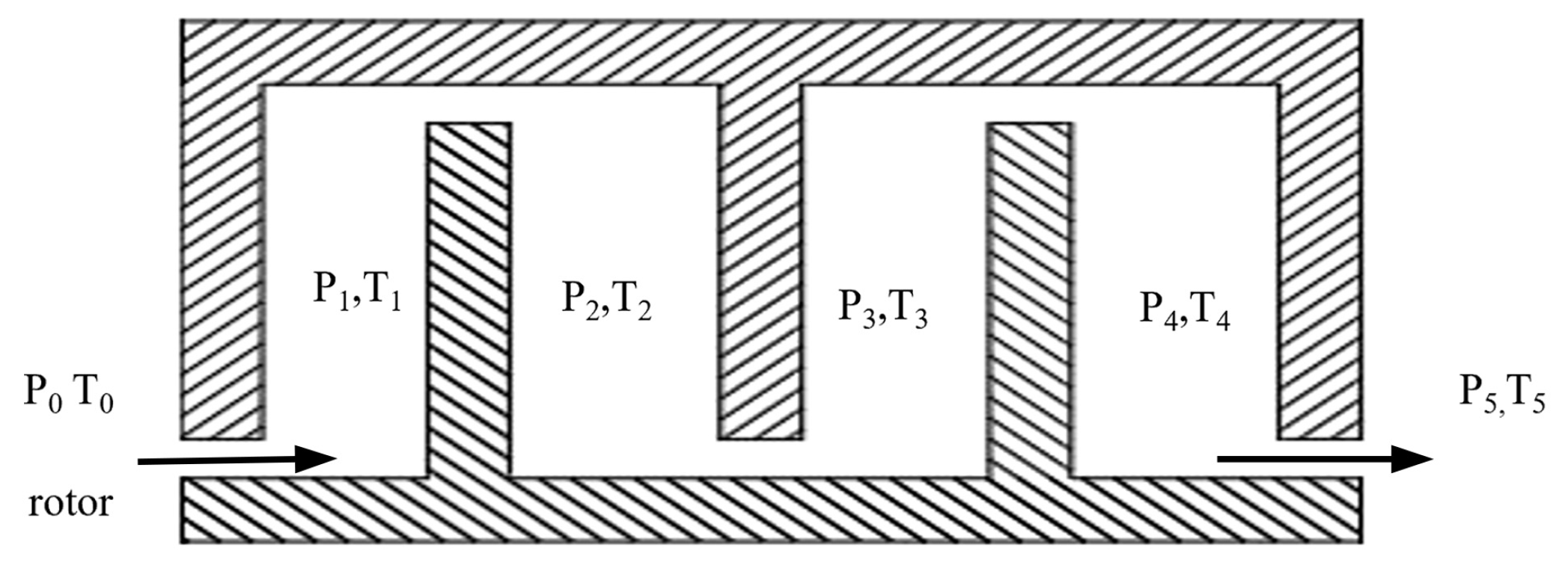
Under the effect of the inlet and outlet pressure differential, the internal lubricating oil in the staggered labyrinth seal flows from the high-pressure inlet to the low-pressure outlet. Assuming that the total inlet pressure of the fluid is P0, the total inlet temperature is T0, the outlet pressure is Pn, and the outlet temperature is Tn, where n represents the sealing stage. Figure 3 is a schematic diagram of the pressure and temperature distribution of the staggered labyrinth seal cavity.
According to the first law of thermodynamics, the sum of energies in a system remains constant. It is assumed that there is no heat exchange between the thermodynamic system of the staggered labyrinth seal and the outside world, namely, the flow of lubricating oil inside the labyrinth seal is regarded as an adiabatic process. When the lubricating oil flows axially from one sealing cavity into the next sealing cavity in a staggered labyrinth seal, the amount of internal energy change U in the thermodynamic system can be defined as [24,25]
U = C v T i T i 1
where Cv is the constant volume heat capacity, and T is the Kelvin temperature.
In a thermodynamic system, in addition to its inherent internal energy itself, the energy also includes work produced due to the changes in internal pressure or volume in the system. In the thermodynamic system of the staggered labyrinth seal, the pressure distribution of the sealing cavity at all levels is uneven due to the continuous energy conversion and dissipation of the lubricating oil in the staggered labyrinth seal, that is, the pressure in the thermodynamic system changes to perform work on the system, and the enthalpy H is used to measure the parameters of the material energy of the system in thermodynamics [26,27], and H can be defined as
H = U + P V
where P is the pressure and V is the volume in this state.
According to the first law of thermodynamics, the heat exchanged per unit mass of lubricant from one sealed cavity to another sealed cavity, dq, can be found by the following formula.
d q = C p d T T d p R P
Integration of Equation (3) yields the entropy gain Δs [28,29,30,31] of the fluid flowing through the sealed cavity as
Δ s = C p ln T 2 T 1 R ln P 2 P 1
where Cp is the constant pressure heat capacity per unit mass, and R is the specific heat capacity of the lubricating oil.

2.2. Friction Effect in Staggered Labyrinth Seals

2.2.1. Calculation of Resistance Loss Along the Route for Staggered Labyrinth Seals

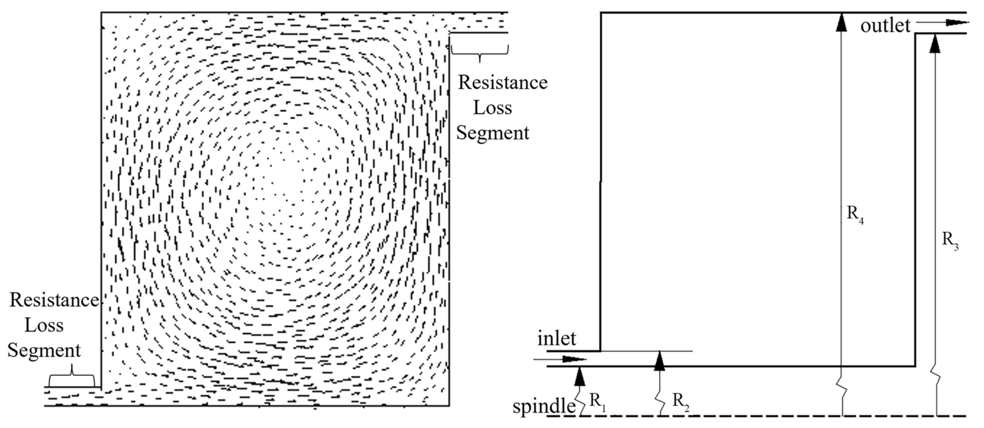
When the lubricating oil flows in the labyrinth sealing device, the resistance loss along the route occurs due to the influence of its own viscosity and the roughness of the inner surface in the sealing device. As shown in Figure 4, the lubricant velocity near the wall is lower than the center of the flow beam. The resistance loss of the staggered labyrinth seal is mainly concentrated in the sealing gap, where the lubricant flow is represented by Q and the sealing gap cross-sectional area is represented by A. The flow rate through the two sealing gaps can be defined as
V 1 = Q 1 A 1 = Q π R 2 2 R 1 2 V 2 = Q 2 A 2 = Q 2 π R 4 2 R 3 2
where R1 is the radius from the spindle to the inner wall of the staggered labyrinth seal inlet, R2 is the radius from the spindle to the outer wall of the staggered labyrinth seal inlet, R3 is the radius from the spindle to the inner wall of the staggered labyrinth seal outlet, and R4 is the radius from the spindle to the outer wall of the staggered labyrinth seal outlet.
The total along-stream pressure loss in a staggered labyrinth seal cavity can be obtained by engineering fluid dynamics.
h r f = λ 1 l v 1 2 4 ( R 2 R 1 ) g + λ 2 l v 2 2 4 ( R 4 R 3 ) g
where v is the speed of lubricating oil, l is the length of the pipeline, and λ1, λ2 are the frictional resistance coefficient along the route related to the roughness of the pipeline.

2.2.2. Calculation of Local Resistance Loss for Staggered Labyrinth Seals

As shown in Figure 5, when the lubricating oil flows along the staggered labyrinth seal, it will also be accompanied by the impact of the fluid particle point due to the change of direction of the flow path or the sharp change in the size and direction of the flow velocity of the variable diameter fluid, which will separate the boundary layer of the fluid and produce vortex. At the same time, the friction and energy exchange will occur between the various particles of the fluid due to the effect of viscosity, which hinders the normal movement of the fluid. Lubricating oil generates local resistance loss and energy loss when flowing into and out of the staggered labyrinth seal cavity [32].
The local resistance loss of the lubricant hlf1 in a staggered labyrinth seal due to the expansion of the flow bundle can be obtained by Bernoulli’s equation.
h l f 1 = V 1 2 2 g 1 A 1 A 2 2 = V 2 2 2 g A 2 A 1 1 2
where V is the flow velocity and A is the cross-sectional area of the sealing gap, g is the acceleration of gravity.
The local drag loss of lubricating oil hlf2 in a staggered labyrinth seal due to abrupt contraction of the watershed can be defined as
h l f 2 = 0.5 V 1 2 2 g 1 A 2 A 1 2
The total pressure loss of the lubricant flowing through the seal cavity of the staggered labyrinth seal described in Equations (6)–(8) can be defined as the following equation.
Δ P = ρ g Q 2 2 g A 1 λ 1 l 1 2 ( R 2 R 1 ) + λ 2 l 2 2 ( R 4 R 3 ) A 1 A 2 2 + 1.5 1 A 1 A 2 2
Considering both the thermodynamic effect and the friction effect, the leakage function of the lubricating oil flowing through a sealing cavity of the staggered labyrinth seal can be defined as
P 1 e Δ s R T 2 T 1 C p R = ρ g Q 2 2 g A 1 λ 1 l 1 2 ( R 2 R 1 ) + λ 2 l 2 2 ( R 4 R 3 ) A 1 A 2 2 + 1.5 1 A 1 A 2 2 + P 1
In Equation (10), Q is the amount of lubricating oil leaking through a sealed cavity. When the lubricating oil flows in a multi-stage labyrinth seal, the energy loss of the lubricating oil due to the frictional effect increases, and the thermodynamic effect is more obvious.

3. Parametric Simulation of the Flow Field of a Staggered Labyrinth Seal

3.1. Governing Equations and Turbulence Models

Considering that the labyrinth seal leakage is closely related to the fluid motion, the state of fluid motion can all be described according to the corresponding equations of the three major theorems.
The conserved differential form of the continuity equation is shown in Equation (11).
P t + ρ V = 0
where ρ is the fluid density and V is the velocity of the fluid.
The momentum equation can be defined as
ρ d U d t = ρ f x + t x x x + t x y y + t x z z P x ρ d V d t = ρ f y + t y y y + t x y x + t z y z P y ρ d W d t = ρ f z + t z z z + t z x x + t z y y P z
The equation shows the momentum component of the viscous flow on the left side, while the sum of the volume force component and the surface force component acting on the fluid micro cluster is shown on the right side. The fluid density is represented by ρ, and f represents the volume force per unit fluid micro cluster.
The energy equation can be defined as
Δ U = Q W
The change in internal energy (ΔU) is determined by the amount of heat energy (Q) and work (W) done on the system.
The turbulent flow state of lubricating oil in the staggered labyrinth seal is described using the standard k-ω turbulent flow model. This is because the lubricating oil flows through the seal as a two-dimensional steady-state turbulent flow, and due to the compressibility of the lubricating oil and the shear flow caused by spindle rotation.
The standard k-ω turbulent flow model can be defined as
ρ k t + ρ K u i x i = x i Γ k K x i + G K Y K + S K ρ ω t + ρ ω u i x i = x i Γ ω ω x i + G ω Y ω + S ω
where ρ is the fluid density, k is the turbulent kinetic energy, ω is the dissipation rate, GK denotes the turbulent kinetic energy generated by the mean velocity gradient; Gω denotes the generation of ω; Γk and Γω represent the effective diffusion coefficients of k and ω, respectively; YK and Yω denote the dissipation of k and ω under turbulence; SK and Sω are user-defined source terms.

3.2. Parametric Simulation

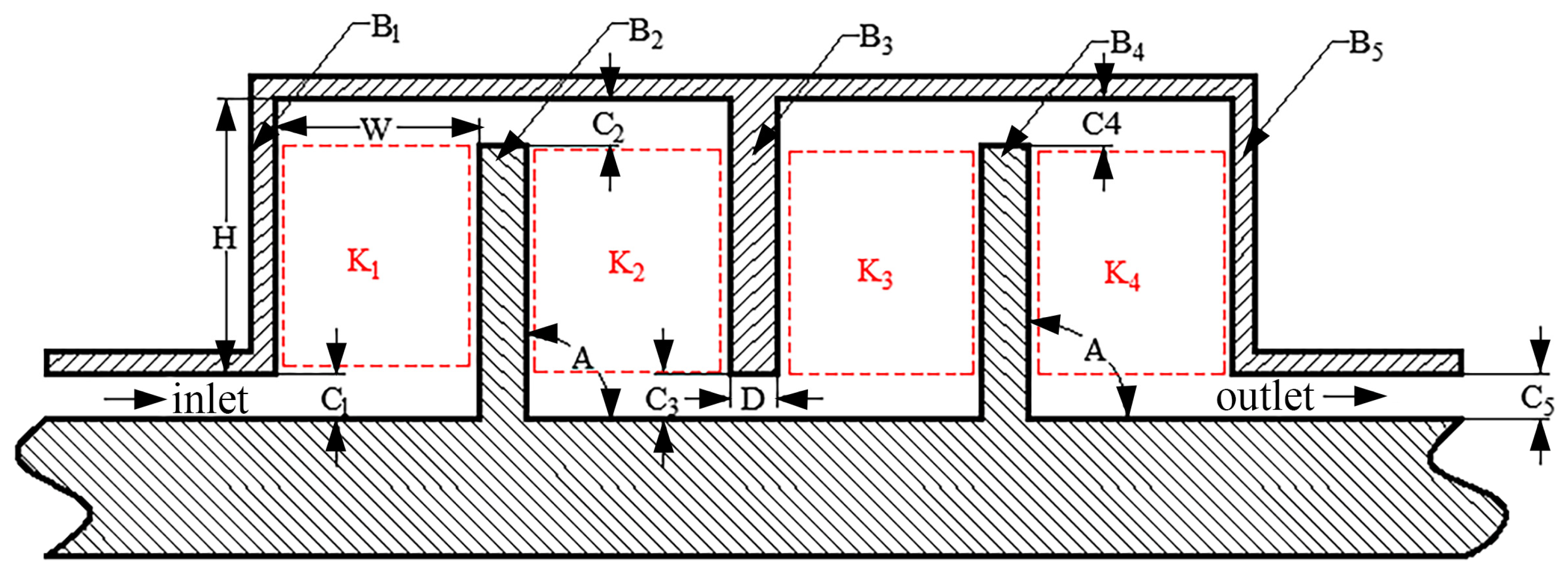
The Design Molder module in Ansys CFX is used to perform parametric modeling of the staggered labyrinth seal watershed. The sealing gap, sealing cavity depth, and sealing cavity width dimensions are defined parametrically. Table 1 shows the parameters for each dimension of the staggered labyrinth seal. The model has been meshed and the boundary conditions have been set, converged, and finally solved and analyzed using finite element theory with the corresponding solver. Figure 6 shows the structure of the original staggered labyrinth seal.
This paper utilizes the commercial software Ansys Meshing2023R1 for local and overall meshing processing. The fluid domain’s primary locations are encrypted for mesh processing. Table 2 shows the working conditions of the labyrinth seal when operating on the sealing device. The inlet boundary is set for a pressure range between 1.1- and 2-times atmospheric pressure, while the outlet boundary is set as a standard atmospheric pressure. The purpose is to investigate the leakage of the staggered labyrinth seal at different speeds, with a rotor wall speed range from 300 to 1200 rpm. The convergence targets for turbulent [33,34] kinetic energy and turbulent dissipation are specified as 10−3.
As shown in Table 3, this paper considers the working conditions of the labyrinth sealing to set the parameter range of the main influencing factors of the sealing device, so as to simulate the watershed under different conditions. The inlet pressure ranges from 1.1 to 1.8 times atmospheric pressure, the spindle speed ranges from 300 to 1200 rpm and the sealing gap ranges from 3 to 10 mm.

3.3. Simulation Results of Leakage Characteristics of Staggered Labyrinth Seals Under the Main Influencing Factors

3.3.1. Grid-Independent Verification

In order to guarantee the precision and efficacy of the calculation while simulating the leakage of the staggered labyrinth sealing device, it is essential to ascertain the irrelevance of the mesh and determine the number of meshes that can guarantee the accuracy and efficient calculation. By modifying the minimum edge size to obtain varying mesh numbers under the same meshing method, the leakage of the staggered labyrinth sealing device can be simulated. Figure 7 illustrates that the leakage of the interleaved labyrinth sealing device varies with grid number. As the grid number increases, the leakage initially decreases and then increases. At grid number 542,424, the leakage does not change smoothly with increasing grid number. Considering the precision and computational efficiency, the leakage of the interleaved labyrinth sealing device is not significant. The optimal number of meshes was determined to be 542,424.

3.3.2. Effect of Total Inlet Temperature on Leakage Characteristics

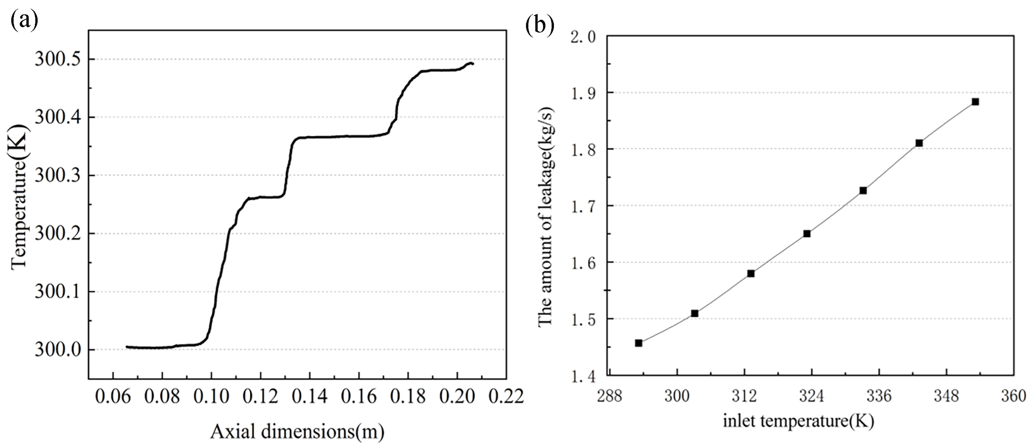
The kinetic energy and pressure energy conversion that occurs in staggered labyrinth seal work results in the conversion of a portion of the kinetic energy into internal energy dissipation. Additionally, the pressure distribution within the cavity is not uniform, leading to an uneven temperature distribution within the cavity. The flow of lubricant through the various sealing cavities, influenced by changes in temperature, causes a notable alteration in lubricant viscosity, which subsequently affects the sealing performance of the sealing device. This paper considers the operational temperature of the staggered labyrinth seal to be 40 °C (313.15 K).
As the temperature rises, the L-ckc320 lubricant power viscosity gradually decreases, resulting in enhanced fluidity. Figure 8a illustrates the temperature distribution curve for the L-ckc320 lubricant within the sealing cavity of a staggered labyrinth seal. As can be observed in the figure, the temperature distribution of the lubricant within the various sealing cavities of the device is not uniform, with a gradual increase in temperature. As the temperature rises, the viscosity of the lubricant decreases, enabling a more fluid flow and greater smoothness within the staggered labyrinth seal. However, this also leads to an increase in leakage and a subsequent deterioration in sealing performance. As illustrated in Figure 8b, the leakage of the staggered labyrinth seal is directly proportional to the total inlet temperature. As the working temperature increases, the leakage of labyrinth seals becomes more severe. Severe loss of liquid medium can deteriorate the working environment of labyrinth seals and reduce their working life.

3.3.3. Effect of Total Inlet Pressure on Leakage Characteristics

The gearboxes discussed in this paper are lubricated using a thin oil station that applies pressure to the injection line to achieve different degrees of lubrication for the gears. The pressure in the gearbox increases when the injection line is in operation. The lubricant enters the staggered labyrinth seal due to the internal pressure of the gearbox, and the amount of leakage varies with the lubricant flow and pressure. The relationship between leakage and total inlet pressure is shown in Figure 9.
At various inlet pressures, the fluid will flow through the labyrinth cavity and into the next sealing cavity. Vortexes are produced by the fluid in the center of the labyrinth cavity, resulting in the dissipation of kinetic energy and a decrease in the velocity of the fluid near the center of the cavity. As the fluid flows through the sealing gap, there will be a pressure drop, causing an increase in the fluid velocity in the direction of flow. However, the fluid flow rate is still relatively small, the fluid will flow downward due to gravity after passing through the vane. As a result, there is a tendency for the flow velocity to increase in the direction of the flow bundle and near the seal gap.
In Figure 9a, the lubricant is under 1.1 times atmospheric pressure. It can be observed that the initial kinetic energy of the lubricant is very low due to the small difference in entrance and exit pressure. At a spindle speed of 700 rpm, the lubricant has difficulty flowing into the seal cavity and the flow beam into the port of the lubricant is reduced. Only a small amount of lubricant flows smoothly through the seal gap into the next seal cavity. Figure 9b shows that when the pressure ratio increased to 1.5, the inlet pressure increased, resulting in the lubricant having a larger initial energy. This caused an increase in the lubricant flow into the staggered labyrinth seal, which in turn increased the beam and leakage. Figure 9c shows that as the inlet pressure ratio increases to 1.8, the lubricant flow beam through the seal gap in the seal cavity increases significantly, resulting in a significant increase in leakage. Based on the above analysis, it can be verified that Figure 9d shows that as the inlet pressure increases, the flow into the seal chamber increases, the leakage of the staggered labyrinth seal increases. As the inlet pressure increases, the leakage of labyrinth seals becomes more severe. Severe loss of liquid medium can deteriorate the working environment of labyrinth seals and reduce their working life.

3.3.4. Effect of Spindle Speed on Leakage Characteristics

As the rotor rotates at high speed, the lubricating oil in the staggered labyrinth seal flows along the axial direction due to inlet pressure. But the lubricating oil experiences hindrance due to the circumferential speed caused by the spindle’s high-speed rotation. This hindrance affects the seal’s leakage. The flow rate of the lubricating oil through the seal gap changes significantly as the spindle speed increases.
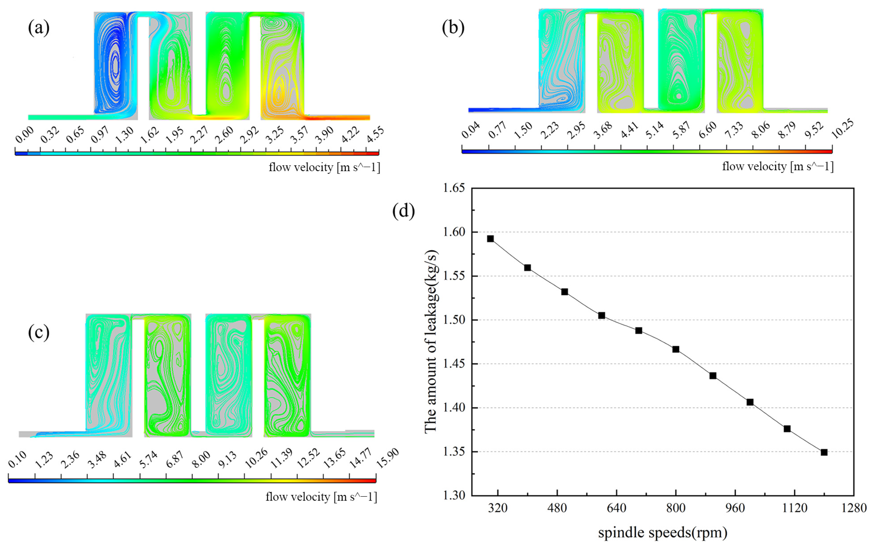
Figure 10a illustrates that the fluid’s kinetic energy decreases as it flows through the second sealing cavity due to the moiré effect and thermal energy loss. This reduction in energy prevents the fluid from overcoming the circumferential velocity to continue flowing into the next seal cavity, resulting in a decrease in leakage volume. When the rotational speed is increased to 700 rpm, the streamline cloud diagram of the lubricant in the staggered labyrinth seal is shown in Figure 10b. Turbulence occurs near the rotor wall surface after the lubricant enters the first seal cavity, causing a significant dissipation of kinetic energy in the flow process. At the same time, the high-speed rotation of the spindle impedes the axial movement of the lubricant, preventing it from entering the next sealing cavity and significantly reducing the flow rate through the sealing gap. When the rotational speed reaches 1200 rpm, the flow pattern of the lubricant inside the staggered labyrinth seal is shown in Figure 10c. It is evident that as the spindle speed increases, the lubricant in the interlaced labyrinth seal cavity becomes more disturbed, resulting in turbulent flow. Additionally, the lubricant flow through the sealing gap decreases with increasing speed.
Based on the analysis above, it is evident that the lubricating oil has a circumferential velocity around the spindle inside the labyrinth sealing device due to the high-speed rotation of the spindle. The leakage varies with the speed as follows: as the spindle speed increases, the flow of lubricating oil along the axial direction of the staggered labyrinth seal becomes increasingly difficult. This obstruction becomes more pronounced at higher speeds. According to the analysis above, Figure 10d confirms that the leakage of the staggered labyrinth seal decreases as the spindle speed increases. When the spindle speed is very low, the leakage of the labyrinth seal becomes more severe. An appropriate increase in spindle speed will reduce labyrinth seal leakage and prolong its working life. However, excessive spindle speed can exacerbate the wear of the labyrinth seal and reduce its working life.

3.3.5. Effect of Seal Clearance on Leak Characteristics

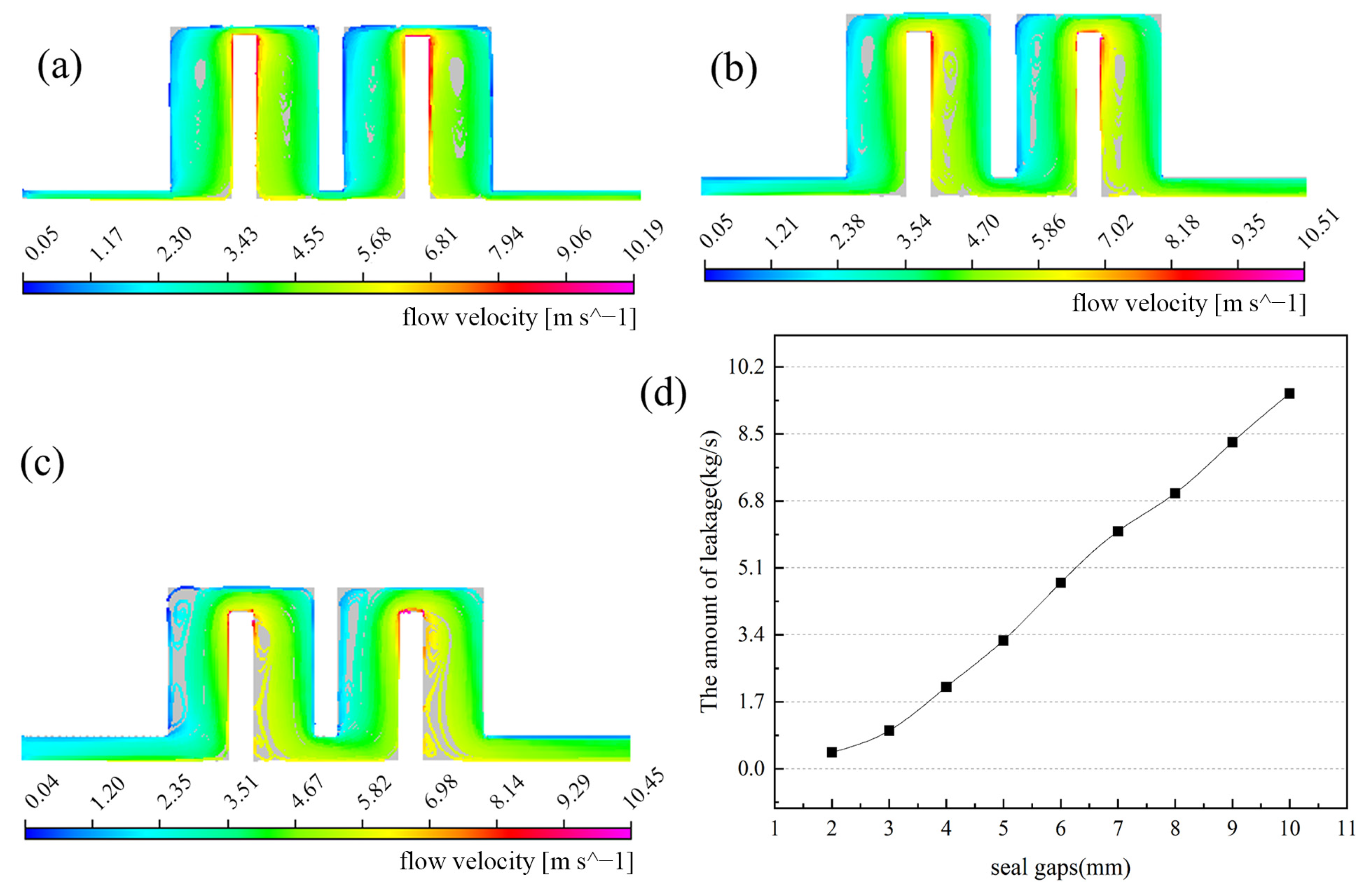
The velocity of the fluid tends to increase in the direction of the flow beam and close to the seal gap. A change in the seal gap alters the local resistance of the lubricating oil as it flows through the seal gap. The larger the seal gap, the smaller the local resistance, resulting in an increase in the flow beam into the labyrinth cavity. Meanwhile, the larger the sealing gap, the smaller the pressure drop, causing the flow rate of the beam into the labyrinth cavity becomes smaller. This results in a more stable fluid and a smaller eddy current area generated in the cavity, leading to less kinetic energy loss. The majority of the kinetic energy of the lubricating oil in the sealing cavity does not convert into internal energy. Instead, it flows directly into the next sealing stage. This reduces the sealing performance of the staggered labyrinth seal and increases the amount of leakage.
Figure 11a is a streamline contour with a sealing gap of 3 mm, which shows that the eddy current area in the labyrinth seal is larger due to the small sealing gap, and more kinetic energy is dissipated. The lubricating oil flows into the next sealing stage through multiple eddy currents, resulting in less leakage. As shown in Figure 11b, the eddy current area in the labyrinth seal is smaller, and the kinetic energy dissipated is less. Lubricating oil flows more easily into the next sealing stage and ends up leaking more. As shown in Figure 11c, when the sealing clearance is increased to 10 mm, the eddy current area is further reduced, the lubricating oil is more likely to flow into the next sealing stage, the leakage is further increased. Based on the analysis above, it is evident that Figure 11d demonstrates an increase in fluid flow into the next sealing stage as the seal gap widens. This is due to a decrease in kinetic energy dissipated by the eddy current, resulting in an increase in leakage of the staggered labyrinth seal. As the sealing gap increases, the leakage of labyrinth seals becomes more severe. Severe loss of liquid medium can deteriorate the working environment of labyrinth seals and reduce their working life.

4. Experimental Verification of Staggered Labyrinth Seals

4.1. Staggered Labyrinth Seal Leakage Test Bench

The section above presents the theoretical derivation of the leakage amount of a staggered labyrinth seal for lubricating oil medium. Additionally, it investigates and discusses the flow characteristics of lubricating oil inside the staggered labyrinth seal, as well as the leakage law of the staggered labyrinth seal under different influencing factors. This section describes the experimental setup used to verify the theoretical calculation of the leakage volume of the staggered labyrinth seal and to investigate the leakage law under different conditions. Figure 12 shows the experimental setup used to measure the leakage of the staggered labyrinth seal.
The experimental bench consists of a speed-regulating motor, pressure gauge, intelligent temperature control display instrument, labyrinth sealing, pressure reducing valve, and hydraulic system. The measurement of lubricating oil leakage and the monitoring of temperature can be realized through the above-mentioned staggered labyrinth seal leakage test bench. The blades to be studied are installed on the rotating spindle through the shaft sleeve, the sealing gasket is installed, and the sealant is applied. Turn on the speed-regulating motor and the gear pump. Fill the entire pipeline with lubricating oil for a period of time. Turn off the speed-regulating motor and the gear pump. Observe the volume of lubricating oil in the beaker and convert any observed lubricating oil leakage.
In order to further explain the leakage characteristics of the staggered labyrinth sealing, the leakage patterns were investigated under different working conditions. The effects of the total inlet pressure, sealing clearance, and spindle speed on the leakage of the staggered labyrinth sealing were studied by using the scheme under the main influencing factors. The specific test parameters in this test protocol are shown in Table 4. In order to study the influence of the total inlet pressure, sealing clearance, and spindle speed on the leakage of the labyrinth sealing, the leakage of the staggered labyrinth sealing was evaluated by reading the volume of lubricating oil flowing into the beaker. In order to minimize human operation error and machine error, each test was repeated at least three times, and the average of the three tests was taken as the test result.
The results shown in this subsection are a comparison of the experimental simulation of the labyrinth seal after the optimized structure, with the aim of verifying the leakage of the optimized labyrinth seal and also doing a comparative qualitative study with the pre-optimization. The specific dimensional parameters of the optimized labyrinth seal is shown in Table 5.

4.2. The Results and Discussion of the Leakage Test of the Staggered Labyrinth Seal

4.2.1. The Influence of the Total Inlet Pressure on the Leakage of the Staggered Labyrinth Seal Was Verified by the Test

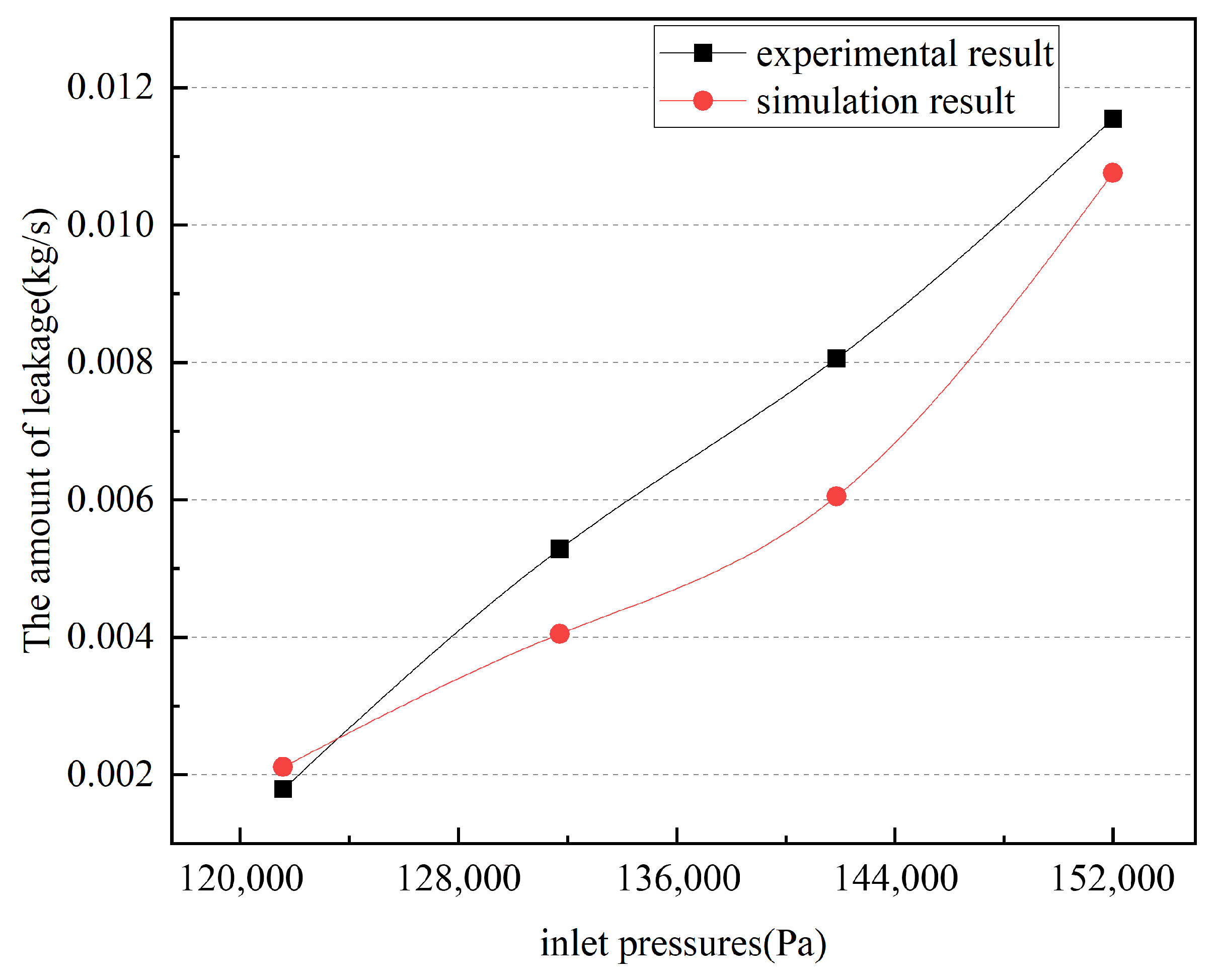
Based on the analysis above, the total pressure at the inlet is the primary factor affecting the leakage of the staggered labyrinth sealing device. To conduct the leakage experiment, the total inlet pressure was set to 121,590 Pa, 131,722.5 Pa, 141,855 Pa and 151,987.5 Pa by adjusting the opening of the pressure reducing valve. The test results, as shown in Figure 13, were compared with the simulation results.
As can be seen from Figure 13, the experimental results are consistent with the simulation results regarding the influence of total inlet pressure on the leakage of the staggered labyrinth sealing. The leakage of the labyrinth sealing increases as the total inlet pressure increases. Additionally, the sealing device’s leakage becomes more pronounced as the pressure increases. Figure 13 shows that the simulation results range from 0.00211 kg/s to 0.01076 kg/s, while the experimental results range from 0.00179 kg/s to 0.01155 kg/s. The maximum deviation between the two sets of results is 0.002 kg/s. As the pressure increases, the impact of the lubricant on the sealing vanes also increases, generating radial forces on the spindle and affecting the coaxiality of the spindle and the staggered labyrinth seal. The coaxiality set in the simulation process does not change, thus making the experimental value slightly larger than the simulation value at higher pressures. Therefore, the experimental results are different from the simulation results, showing an approximate linear change in the results. The relative errors between the simulation and experimental results at each point in the graph are 18.1%, 23.4%, 24.9%, and 6.8%, in that order.

4.2.2. The Influence of Spindle Speed on the Leakage of Staggered Labyrinth Sealing Device Was Verified by the Test

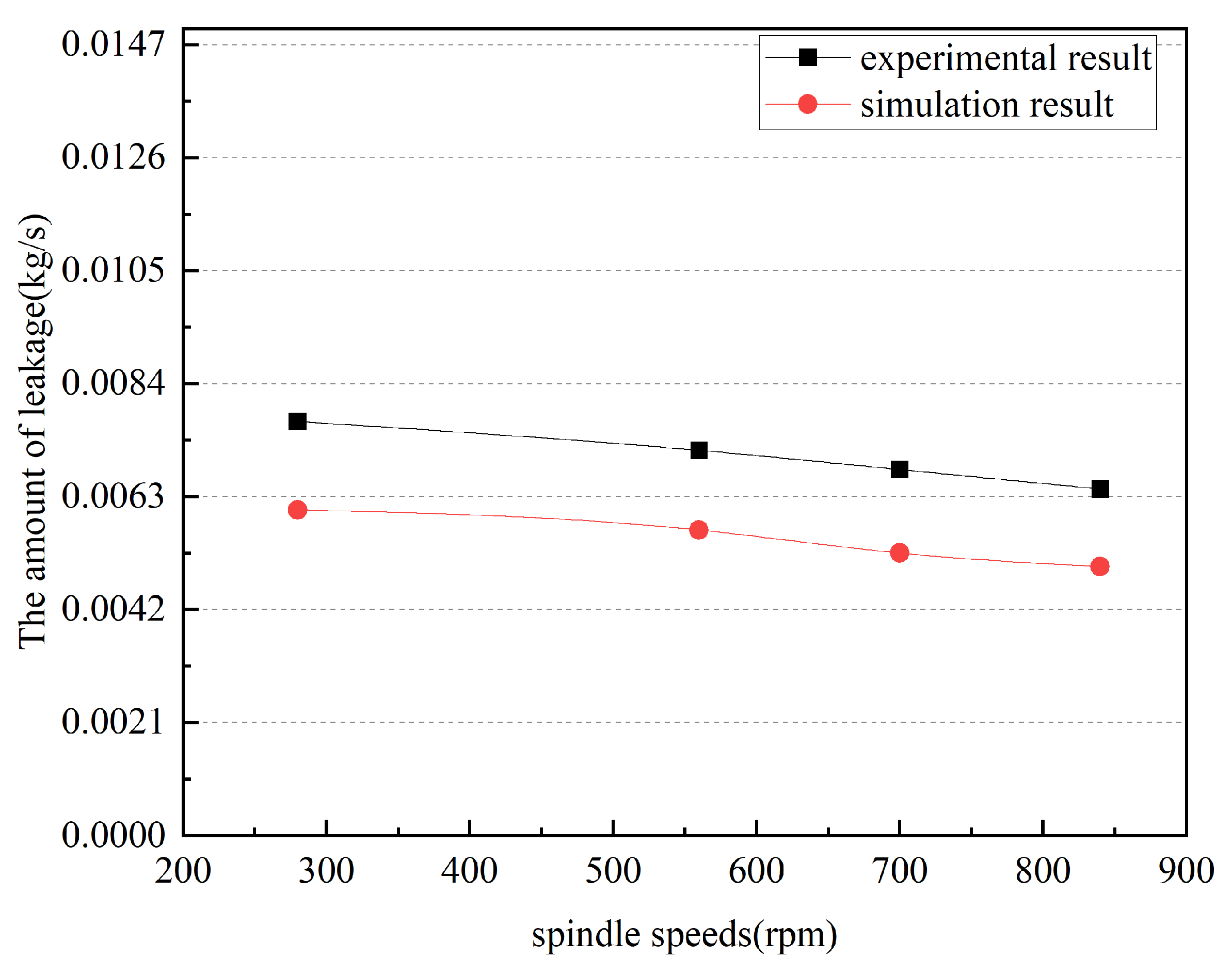
In the staggered labyrinth sealing, the spindle speed range is between 500 rpm and 1200 rpm, and the leakage test is selected at 280 rpm, 560 rpm, 700 rpm and 840 rpm respectively. The test data were compared to the simulation data, as depicted in Figure 14, which shows the comparison curve between the test and simulation results.
Figure 14 shows that the experimental and simulation results both indicate that the leakage of the staggered labyrinth seal decreases with increasing speed. Additionally, the lubricating oil leakage decreases faster at higher speeds. This is due to the centrifugal force causing a slight increase in the diameter of the sealing blade, resulting in a smaller sealing gap and less leakage. The descriptions of leakage at different speeds in Figure 14 are nearly identical. Within the tested speed range, the maximum experimental value of staggered labyrinth seal leakage is only 0.001257 kg/s higher than the minimum value. This suggests that the speed has little influence on the leakage of the staggered labyrinth seal, and in some practical engineering applications, the speed’s effect on labyrinth seal leakage can be disregarded. The relative errors between the simulation and experimental results at each point in the graph are 21.4%, 20.7%, 22.8%, and 22.4%, in that order.

4.2.3. The Influence of Seal Clearance on the Leakage of Staggered Labyrinth Seal Was Verified by Experiment

The simulation of the flow field in the staggered labyrinth seal shows that as the sealing gap increases, the lubricant is more likely to flow through the device’s gap, resulting in increased leakage. To investigate the leakage of the staggered labyrinth seal under different sealing gaps, an experimental bench was constructed, and the experiments were conducted. As can be seen from Figure 15, the study compared experimental and simulation results for sealing gaps of 1 mm, 3 mm, 5 mm, and 7 mm using staggered labyrinth seals. Both sets of results indicate that seal leakage increases with larger sealing gaps. The relative errors between the simulation and experimental results at each point in the graph are 4.5%, 9.5%, 4.9%, and 6.1%, in that order. The maximum deviation between experimental and simulated values occurred at a sealing gap of 3 mm, with a difference of 9.497%.

4.3. Experimental Verification of the Leakage Calculation Method of Staggered Labyrinth Seal Under Multiple Effects

A new method for calculating the leakage volume of staggered labyrinth seals was proposed in the above section, taking into account the friction effect as well as the thermodynamic effect. In this section, a staggered labyrinth seal leakage test bench is utilized for validation. The entropy increase in lubricant flow through the seal is calculated by monitoring the temperature and pressure of each sealing cavity, thus validating Equation (10). Table 6 shows the use of thermocouple temperature sensors on the optimized staggered labyrinth seal. The temperature distribution of the cavity was measured in three groups of experiments, with each group consisting of three measurements. The final results were obtained by averaging the measurements.
At the same time, in the staggered labyrinth seal of each seal cavity, the pressure distribution measurement was performed. By adjusting the pressure reducing valve, the total inlet pressure of the lubricating oil into the interlaced labyrinth seal device was set to 141,855 Pa. Three measurements were made on the same seal cavity, and the average of the three sets of pressure values was taken as the experimental results.
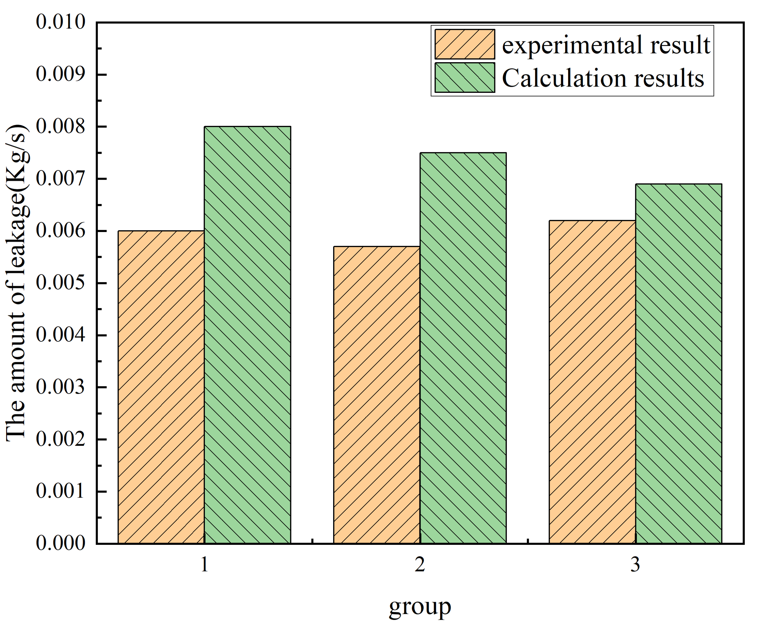
According to the average temperature and pressure average value in the above table, the entropy increase in the lubricating oil flowing through the cavity of a staggered labyrinth sealing is calculated by Equation (4). The calculation results were brought into the new leakage calculation formula, and the theoretical value of lubricating oil leakage was obtained. The experimental results were compared with the experimental results, as shown in Figure 16, which is a comparative histogram of the experimental value and the theoretical value of the leakage of the staggered labyrinth seal.
As shown in Figure 16, it can be seen that after three sets of leakage tests, the experimental values are basically consistent with the theoretical values of the description of the leakage of the staggered labyrinth seal. To a certain extent, the staggered labyrinth seal leakage calculation model proposed in this paper can better reflect the real leakage, but the theoretical value is greater than the actual value because the friction effect is not considered.

5. Conclusions

In this paper, the leakage characteristics of staggered labyrinth seals under different influencing factors were compared and analyzed, and the effects of different inlet total pressure, seal clearance, and spindle speed on the leakage characteristics of labyrinth seals were evaluated. The purpose was to provide guiding recommendations for improving the working performance and prolonging the service life of staggered labyrinth seals. The main findings are summarized below:
(1)
A method for calculating the leakage of staggered labyrinth seals considering thermodynamic effects and frictional effects under liquid medium was proposed.
(2)
The leakage characteristics of labyrinth seals were investigated by comparing experimental and simulation results. Based on the calculation method of leakage under liquid medium, a method of calculating the leakage of staggered labyrinth seals considering the friction effect and thermodynamic effect was proposed, and the traditional calculation method was optimized. At the same time, corresponding simulation analyses were carried out, and the results showed that the leakage volume of the staggered labyrinth seal is different under different influencing factors, and the leakage volume is directly proportional to the total inlet pressure and the sealing gap, and inversely proportional to the spindle speed.
(3)
Verification experiments were designed, and the experimental results were compared with the theoretical values and simulation results to verify the accuracy of the theory. The experimental results showed that the leakage calculation method proposed in this paper can calculate the leakage and has reference significance to a certain extent.
It is worth noting that the calculation of the leakage of the staggered labyrinth seal is not only related to the consideration of the frictional effect and the thermodynamic effect, but also the beam shrinkage effect and the air permeability effect. Therefore, the study of the effect of beam shrinkage and the effect of the breathability effect on the leakage of staggered labyrinth seals will be carried out soon for the second phase of this work.

Author Contributions

Conceptualization, N.W. and S.-B.C.; Methodology, N.W. and S.-B.C.; Validation, N.W., Y.C. and Z.S.; Formal analysis, N.W. and S.-B.C.; Investigation, N.W. and S.T.; Resources, N.W. and S.T.; Data curation, N.W., Y.C. and Z.S.; Writing—original draft, N.W., Y.C. and Z.S.; Writing—review & editing, N.W., Y.C. and S.-B.C.; Visualization, N.W.; Supervision, N.W.; Project administration, N.W. All authors have read and agreed to the published version of the manuscript.

Funding

This project was supported by the National Natural Science Foundation of China (Grant No. 52005085).

Data Availability Statement

The data used to support the findings of this study are included in the manuscript.

Conflicts of Interest

Author Zhencong Sun was employed by the company Guangzhou KEYSEMI Technology Co., Ltd. The remaining authors declare that the research was conducted in the absence of any commercial or financial relationships that could be construed as a potential conflict of interest.

References

  1. Zhang, M.J. Study of Flow Characteristics and Efficiency Improvement Technology for Turbine Seal. Master’s Thesis, Southeast University, Nanjing, China, 2017. [Google Scholar]
  2. Lin, M. 3D Flow Field Analysis and Piston Structure Optimization for Reciprocating Compressor Based on CFD. Master’s Thesis, Shenyang Ligong University, Shenyang, China, 2013. [Google Scholar]
  3. Wang, Y.F.; Zhang, W.F.; Pan, B.; Li, C. Effect of shaft misalignment on dynamic and static characteristics of interlocking labyrinth seals. Hangkong Xuebao 2020, 41, 212–223. [Google Scholar]
  4. Yang, Y.L. Flow Fields Study and Rotordynamic Analysis of Labyrinth Seals. Master’s Thesis, Huazhong University of Science & Technology, Wuhan, China, 2006. [Google Scholar]
  5. Li, Y.H. Research the Characteristics of the Large Motor Sliding Bearing Labyrinth Seal Resisting Negative Pressure. Master’s Thesis, Xiangtan University, Xiangtan, China, 2015. [Google Scholar]
  6. Zhang, Y.; Zhang, K.L.; Yao, Y.; Wang, X.P. Numerical Analysis of the Rotor Speed Effect on Labyrinth Seal Characteristics. Mach. Des. Manu. 2017, 3, 183–185. [Google Scholar]
  7. Zhang, Y. Numerical Analysis of Flow Filed and Labyrinth Seal for High-Speed Train Gearbox. Master’s Thesis, Southewest Jiaotong University, Chengdu, China, 2016. [Google Scholar]
  8. Yucel, U.; Kazakia, J.Y. Analytical prediction techniques for axisymmetric Flow in Gas Labyrinth Seals. J. Eng. Gas Turbines Power 2001, 123, 255–257. [Google Scholar] [CrossRef]
  9. Wang, C. The Research of Locomotive Traction Gear Box Sealing Device Internal Flow Field and Structure Optimization Design. Master’s Thesis, Dalian Jiaotong University, Dalian, China, 2015. [Google Scholar]
  10. Subrnabuab, S.; Sekhar, A.S. Prasad BVSS. Rotordynamic Characterization of Rotating Labyrinth Gas Turbine Seals with Radial Growth: Combined Centrifugal and Thermal Effects. Int. J. Mech. Sci. 2017, 123, 1–19. [Google Scholar]
  11. Jia, W.C.; Xu, H.H.; Wei, L.H. Orthogonal Simulation Test and Optimization for Leakage of Labyrinth Seal in High Speed Gear Box. Lubr. Eng. 2018, 43, 126–131. [Google Scholar]
  12. Yuan, J.B.; Shi, X.X.; Hu, T.; Mei, Z.J. Summarize on the Labyrinth Seal Research for High Speed Gear Box. Hydr. Pneu. Seals 2019, 39, 72–77. [Google Scholar]
  13. Martin, M. Labyrinth Packings. Engineering 1980, 1, 35–36. [Google Scholar]
  14. Zhu, G.T. Analysis of Leakage Character of a Labyrinth Piston Compressor. Master’s Thesis, Nanjing University of Aeronautics and Astronautics, Nanjing, China, 2006. [Google Scholar]
  15. Egli, A. The Leakage of Steam Through Labyrinth Seals. Trans. ASME 1935, 57, 115–122. [Google Scholar] [CrossRef]
  16. Kearton, W.J.; Keh, T.H.; Eng, D. Leakage of Air through Labyrinth Glands of Staggered Type. Proc. I Mesh. E 1952, 166, 319–320. [Google Scholar] [CrossRef]
  17. Zhu, G.T.; Liu, W.H. Analysis of Calculational Methods on Leakage for Labyrinth Seals. Lubr. Eng. 2006, 176, 123–126. [Google Scholar]
  18. Zhai, L.; Zhu, Z.; Zhang, Z.; Guo, J.; Cui, B. Theoretical Solutions for Dynamic Characteristics of Spiral-Grooved Liquid Seals. Tribol. T 2018, 62, 22–33. [Google Scholar] [CrossRef]
  19. Zhou, W.J.; Zhao, Z.B.; Wang, Y.F.; Shi, J.L.; Gan, B.; Li, B.; Qiu, N. Research on leakage performance and dynamic characteristics of a novel labyrinth seal with staggered helical teeth structure. Alex. Eng. J. 2021, 60, 3177–3187. [Google Scholar] [CrossRef]
  20. Han, L.; Wang, Y.; Liu, K.; Ban, Z.; Qin, B.; Liu, H.; Dai, M. Theoretical Leakage Equations Towards Liquid-Phase Flow in the Straight-Through Labyrinth Seal. ASME J. Tribol. 2022, 144, 1448–1462. [Google Scholar] [CrossRef]
  21. Raparelli, T.; Mazza, L.; Trivella, A. Experimental analysis and preliminary model of non-conventional lip seals. Trib. Int. 2023, 181, 108311. [Google Scholar] [CrossRef]
  22. Wang, Y.M.; Liu, W.; Liu, Y. Current Research and Developing Trends on Non-contacting Mechanical Seals. Hydr. Pneu. Seals 2011, 31, 29–33. [Google Scholar]
  23. Lin, L. Theoretical Research on the Principles of Seal in Labyrinth Piston Compressors. Master’s Thesis, Nanjing University of Aeronautics and Astronautics, Nanjing, China, 2007. [Google Scholar]
  24. Li, G.B.; Cui, H. Fundamentals of Fluid Mechanics and Thermal Engineering, 1st ed.; Beijing Institute of Technology Press: Beijing, China, 2016; pp. 58–81. [Google Scholar]
  25. Wei, W.; Wu, J.Q.; Ma, X.D. The Strong about Thermodynamics First Law. J. Xinjiang Norm. Univ. 2011, 30, 59–62. [Google Scholar]
  26. McCulloh, R.S. Treatise on the Mechanical Theory of Heat and Its Applications to the Steam-Engine, Etc, 1st ed.; University of Michigan Library: Ann Arbor, MI, USA, 2005; pp. 77–97. [Google Scholar]
  27. Clausius, R. On the Motive Power of Heat, and on the Laws Which Can Be Deduced from It for the Theory of Heat. Philos. Mag 1865, 40, 1–35. [Google Scholar]
  28. Jaynes, E.T. Information Theory and Statistical Mechanics. Phys. Rev. 1957, 106, 620. [Google Scholar] [CrossRef]
  29. Sun, D.; Lu, J.; Wang, W.; Ai, Y.T.; Wang, Z. Numerical Investigations for Sealing Mechanism of Labyrinth Seals Based on Thermodynamic Effect. Therm. Turbine 2018, 47, 175–181. [Google Scholar]
  30. Lu, J. Study of Labyrinth Seals on Sealing Mechanism and New Vibration Suppression Seal Structure. Master’s Thesis, Shenyang Aerospace University, Shenyang, China, 2019. [Google Scholar]
  31. Xu, W.J.; Wang, L.W. Numerical Study on Leakage and Dynamic Coefficients of Three Types of Labyrinth Seals. Lubr. Eng. 2017, 42, 96–101. [Google Scholar]
  32. Yu, Y.Q.; Zhang, Y.X.; Kang, Y.J. Research on Wellhead at Offshore Platform Based on Straight-through Labyrinth Seal. Hydr. Pneu. Seals 2009, 23, 2830–2838. [Google Scholar]
  33. Tong, S.K.; Cha, K.S. ; Cha, K.S. Comparative analysis of the influence of labyrinth seal configuration on leakage behavior. J. Mech. Sci. Technol. 2009, 23, 2830–2838. [Google Scholar]
  34. Wang, W.Z.; Liu, Y.Z.; Meng, G.; Jiang, P.N. A nonlinear model of flow-structure interaction between steam leakage through labyrinth seal and the whirling rotor. J. Mech. Sci. Technol. 2009, 23, 3302–3315. [Google Scholar] [CrossRef]
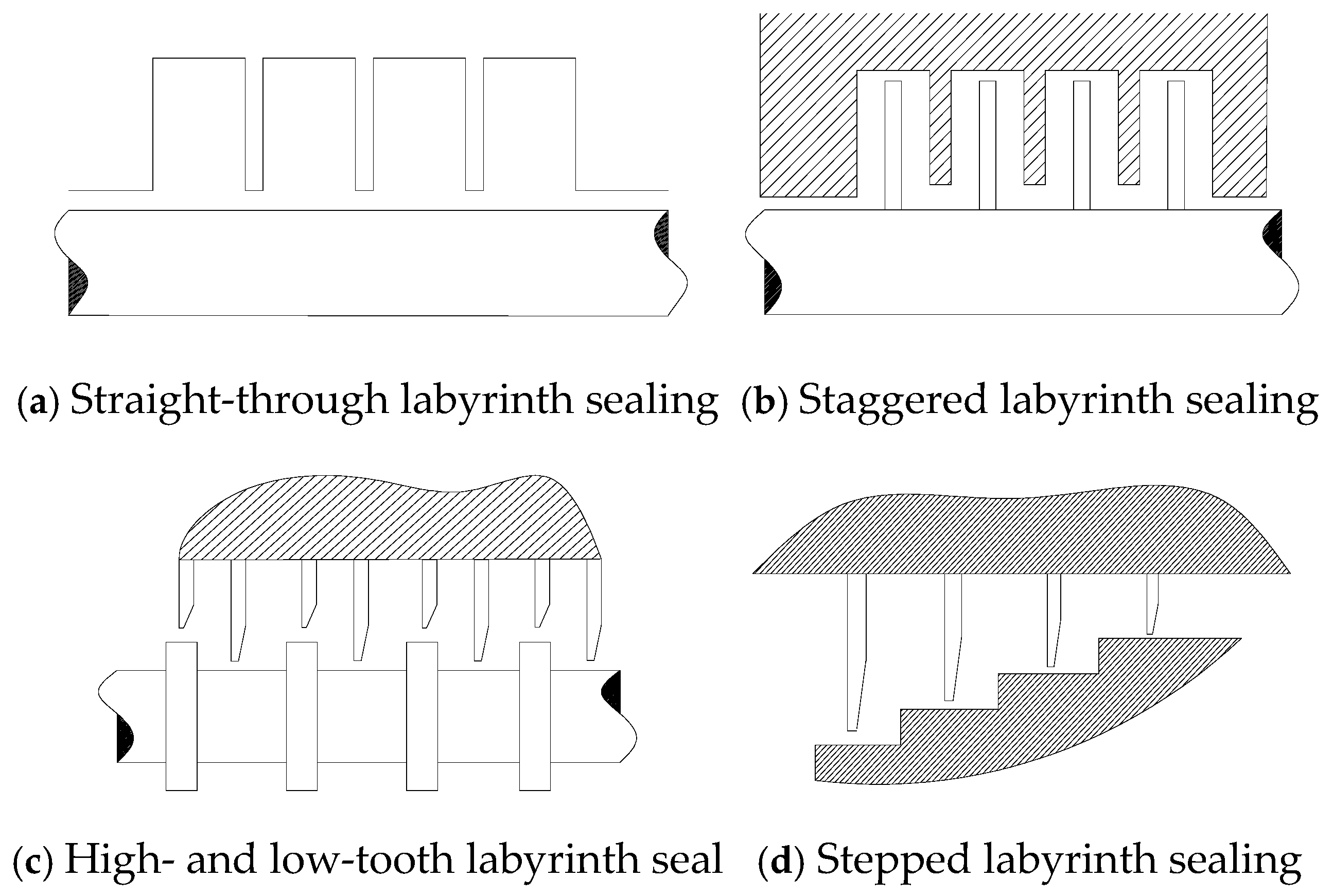
Figure 1. Several typical labyrinth seals.
Lubricants 12 00369 g001
Figure 2. Structural diagram of staggered labyrinth sealing.
Lubricants 12 00369 g002
Figure 3. Schematic diagram of pressure and temperature distribution at all levels of staggered labyrinth seal.
Lubricants 12 00369 g003
Figure 4. Schematic diagram of resistance and dimension of interleaved labyrinth seal cavity.
Lubricants 12 00369 g004
Figure 5. Across-sectional diagram of the flow of lubricants. where V1 is the flow velocity of inlet, V2 is the flow velocity of export; A1 is the cross-sectional area of the inlet, A2 is the cross-sectional area of the export; P1 is the pressure of the inlet, P2 is the pressure of the export.
Lubricants 12 00369 g005
Figure 6. Dimension diagram of staggered labyrinth seal.
Lubricants 12 00369 g006
Figure 7. Grid independence verification.
Lubricants 12 00369 g007
Figure 8. (a) Staggered labyrinth seal cavity temperature distribution. (b) Leakage curves of staggered labyrinth seals at different total inlet temperatures.
Lubricants 12 00369 g008
Figure 9. Streamline diagram with different pressure ratios: (a) 1.1, (b) 1.5, (c) 1.8, and (d) variation of leakage rate of staggered labyrinth seal under different inlet total pressures.
Lubricants 12 00369 g009
Figure 10. Streamline diagram with different speeds: (a) 300 rpm, (b) 700 rpm, (c) 1200 rpm, and (d) variation of leakage rate of staggered labyrinth seal at different speeds.
Lubricants 12 00369 g010
Figure 11. Streamline diagram with different gaps: (a) 3 mm, (b) 7 mm, (c) 10 mm, and (d) variation of leakage rate of staggered labyrinth seal with different gaps.
Lubricants 12 00369 g011
Figure 12. Test bench for leakage characteristics of staggered labyrinth seal.
Lubricants 12 00369 g012
Figure 13. Comparison of experimental and simulated leakage rate of staggered labyrinth seal under different inlet pressures.
Lubricants 12 00369 g013
Figure 14. Comparison of experimental and simulated leakage of staggered labyrinth seal under different spindle speeds.
Lubricants 12 00369 g014
Figure 15. Comparison of experimental and simulated leakage rate of staggered labyrinth seal under different seal gaps.
Lubricants 12 00369 g015
Figure 16. Comparison diagram of theoretical and experimental leakage of staggered labyrinth seal.
Lubricants 12 00369 g016
Table 1. Dimension parameter range of staggered labyrinth seal.
ParameterValue
The length of the entry extension L130 mm
The length of the outlet extension L230 mm
Seal gap C0.5–10 mm
Seal cavity depth H40–100 mm
Width of the sealing chamber W35–80 mm
Blade thickness D10 mm
Blade inclination A90°
Table 2. Boundary conditions of watershed simulation.
ParameterValue
Inlet pressure101,325–20,265,030 Pa
Outlet pressure101,325 Pa
Total inlet temperature293.15–353.15 K
Rotate speed300–1200 rpm
Number of sealing stages4
MediaL-ckc320
Table 3. Range of parameter settings for major influencing factors in watershed simulation.
ParameterValue
Inlet pressure101,325–20,265,030 Pa
Rotate speed300–1200 rpm
Seal gap3–10 mm
Table 4. Test parameter setting of staggered labyrinth seal device.
Group1234
Total inlet pressure (Pa)121,590, 131,722.5,
141,855, 151,987.5
141,855131,722.5131,722.5
Seal gap (mm)3331, 3, 5, 7
Spindle speed (rpm)280280,560,
700,840
280280
Table 5. Structural parameters of optimized staggered labyrinth seal.
Blade Inclination (°)Blade Thickness (mm)Sealing Gap (mm)Cavity Depth (mm)Cavity Width (mm)
8091.57035
Table 6. Average value of cavity temperature and distribution of labyrinth sealing device under three groups of experiments.
Group123
The average temperature of the first seal cavity ( K ¯ )294.25294.25294.3
The average temperature of the second seal cavity ( K ¯ )294.55294.5294.5
The average temperature of the third seal cavity ( K ¯ )294.8294.8294.75
The average temperature of the fourth seal cavity ( K ¯ )294.87295.17295
The average pressure of the cavity of the first seal ( P a ¯ )138,811.3138,249.3138,049.3
The average pressure of the cavity of the second seal ( P a ¯ )136,214136,056135,743.7
The average pressure of the cavity of the second seal ( P a ¯ )128,204.3127,861127,487
The average pressure of the cavity of the first seal ( P a ¯ )125,760.7125,390125,276.3
Disclaimer/Publisher’s Note: The statements, opinions and data contained in all publications are solely those of the individual author(s) and contributor(s) and not of MDPI and/or the editor(s). MDPI and/or the editor(s) disclaim responsibility for any injury to people or property resulting from any ideas, methods, instructions or products referred to in the content.