Article

Sliding Contact Fatigue Damage of Metallic Implants in a Simulated Body Fluid Environment

by
Mihir V. Patel
,
Edward Cudjoe
and
Jae Joong Ryu
*
Rayen School of Engineering, Youngstown State University, Youngstown, OH 44555, USA
*
Author to whom correspondence should be addressed.
Lubricants 2024, 12(12), 437; https://doi.org/10.3390/lubricants12120437
Submission received: 21 October 2024 / Revised: 1 December 2024 / Accepted: 5 December 2024 / Published: 8 December 2024
(This article belongs to the Special Issue Biomechanics and Tribology)

Abstract

:
At the modular interface of the joint implants, repeated contact stresses in a corrosive synovial environment cause surface degradation that worsens over time. The lubricating mechanisms at the joints are altered by the deteriorated synovial fluid by the wear debris and corrosion products. As a result, the joint implants’ unsatisfactory performance will be exacerbated by the synergistic combination of wear and corrosion. In this work, reciprocal sliding contact tests in simulated synovial fluid were conducted on the two main metallic implant materials, CoCrMo and Ti6Al4V. The mechanical and electrochemical reactions were described by monitoring the open-circuit potential (OCP) and coefficient of friction (COF). The electrochemical damage that altered the oxidation chemistry on both surfaces was illustrated by the potentiostatic test findings. The surface damage process of CoCrMo under all contact loads presented unstable chemomechanical responses. On the other hand, the Ti6Al4V results revealed a moderate decrease in fretting current and stable changes in the coefficient of friction. Consequently, the experimental investigation determined that, when mechanical loadings and electrochemical stimulus are combined, Ti6Al4V’s biocompatibility would be superior to CoCrMo’s.

1. Introduction

Total joint replacement (TJR) is considered as among the most challenging treatments in orthopedic surgeries [1]. Because of the decrease in friction at the synovial contact caused by articular cartilage and synovial fluid, normal synovial joints allow for extremely smooth motion between limb segments [2,3]. While referring to the successful repair of injured joints, total joint replacements have been recognized as one of the most effective orthopedic procedures [2,3]. On the other hand, a synthetic joint material is utilized in place of the natural articular cartilage in TJR. The smooth motion and wear protection of the artificial joints are inevitably lost, and the nature of synovial joint lubrication is altered. The strong shearing action that occurs during joint articulation causes subtle tribological issues such as surface fatigue and the wear that follows on the modular joint contacts. Modular interfaces, including the stem-head interface in hip replacements, are constantly susceptible to wear and corrosion, even though the main reason for the modular design of joint replacements is the simplicity of modification for anatomic customization. In periprosthetic tissue, the corrosion products result in osteolysis, and the wear debris migrates both locally and systemically [4,5]. The physiology at the periprosthesis is denaturalized by the multifactorial bio-tribological action of active articulation, and the poor physiopathological state of synovial fluid severely reduces the longevity of joint implants [6,7,8].
The mechanical functions for smooth articulation and load bearing are enhanced by the use of prosthetic implant materials. In biological and physiological settings, local and systemic stability is essential for them to carry out biomechanical tasks in the human body. Metals, ceramics, and polymers are the three primary materials used to create such implantable devices [9,10]. Because of their mechanical and manufacturing benefits, such as a lower probability of fracture, a lower chance of dislocation, and a lower overall loss of material being removed, metal alloys have been shown to be highly preferred for prosthetic implants [11,12]. However, only a few metal alloys, like titanium-based and cobalt-chromium-based alloys, are biocompatible and have proved successful as orthopedic implants for long-term services
The most popular alloys for orthopedic implants and medical devices are titanium (Ti) alloys due to their exceptional mechanical strengths and exceptional inertness in a biochemical environment [13,14]. Titanium exhibits advantageous specific strength (strength/density) when compared to other alloys like cobalt chromium and steels. The titanium alloying elements stabilize the phases and have a significant influence on the transformation temperature between α-HCP and β-BCC [15]. Due to their solubility in both α and β phases and their ability to enhance strength and ductility, aluminum and vanadium elements are present in the majority of commercially available medical-grade titanium alloys [16,17,18]. Commercially pure titanium (ASTM F67) and extra-low interstitial Ti6Al4V alloy (ASTM F136) are the two most widely utilized titanium alloys in implant construction. Because cobalt chromium (CoCr) alloys have stable chemical responses in the human body and high mechanical strength and stiffness, they are used as the bearing components in joint replacements. Moreover, CoCr alloys’ superior hardness leads to outstanding wear resistance. With the inclusion of molybdenum and other elements up to certain limits (ASTM F75 and F1537), cobalt chromium alloys show markedly increased strength and chemical inertness [19,20]. These qualities make them suitable for use in load-bearing joint implant components.
Ti and CoCr alloys, as previously indicated, create a robust passive layer that shields the metal substrate from corrosion attack. To increase the usable life of joint implants, the passive film’s mechanical and chemical stability is crucial. The hard surface layer successfully minimizes friction force by reducing adhesion between the contacting metal surfaces. By creating a kinetic barrier of chemical activation, this passive layer isolates the base metals from the reactive environments around them. Consequently, the oxide layer’s increased hardness and inertness lead to better wear and corrosion resistance against biomechanical stimuli [21,22].
Despite having superior mechanical and chemical qualities, the patient’s regular movements and the corrosive synovial fluids around the implant gradually erode the implant surfaces, which can result in an unanticipated joint failure. The oxide film loses its defense against corrosion attack when joint components rub against one another during active articulations, causing damage to the surface layer [23,24,25]. The enhanced electrochemical potential causes quick metal ion dissolution through the injured surface region, instantly rebuilding the passive layer. In the periprosthetic tissues, dissolved metal ions and corroded wear debris are typically linked to detrimental physiological relationships [26,27]. Recent studies have demonstrated a direct correlation between the high early failure rate of hip implants and the fretting corrosion of the modular taper interfaces of hip joint replacements. However, Ti and CoCr alloys continue to be used in the production of joint implants today because of their superior mechanical and biochemical performance. Despite the CoCr surface’s higher hardness than the Ti alloy surface, the previous investigation of tribocorrosion of metallic implants revealed that the CoCr surface exhibited a higher wear rate under the same mechanical and electrochemical stimuli [28,29,30,31]. Prior research corroborated the hip replacement retrieval studies: the harder CoCr surface at the CoCr–Ti interface exhibited faster wear behavior than the counter-Ti surface [32]. This is due to the fact that when the mechanical damage process occurs in chemically reactive surroundings, the combined complexity alters the damage pathways. Tribocorrosion behaviors are changed by the combination of mechanical loads and a reactive synovial environment, and this eventually results in different degradation processes for Ti and CoCr alloys. CoCr alloys exhibit higher levels of hardness and strength than Ti alloys. It has been established as a result that CoCr joints have a longer lifespan than Ti joints. Nevertheless, despite CoCr’s better mechanical qualities, prior clinical research and in vitro tribocorrosion simulations produced contradictory findings, meaning that the CoCr implant surface exhibited a greater wear rate than the Ti implant surface [12,15].
This research reports on the continuous sliding contact of CoCrMo (F1537) and Ti6Al4V (F136) alloys in a corrosive environment. Fretting contact tests were conducted in a tribochemical cell to comprehend the damage recovery behaviors and chemomechanical synergism of the two distinct oxides. The electrochemical and mechanical changes in the alloy surfaces were studied in a simulated synovial condition of phosphate-buffer saline (PBS). An alumina sphere was subjected to a regulated elastic normal load and allowed to reciprocate cyclically while the potentiostatic condition was monitored for fretting current and OCP. On the surface of the Ti alloy, favorable modifications to the oxide chemistry and passive film recovery process were noted. This outcome clarified how the CoCrMo implant surface showed a higher wear rate than that of the Ti6Al4V implant surface.

2. Materials and Experimental Description

Medical grade CoCrMo (F1537) and Ti6Al4V (F136) rectangular rods were machined into a test specimen of 1.00 × 2.54 × 22.95 mm3 using the electrical discharge machining (EDM) method to minimize the effect from residual stresses. Specimens were implanted in an epoxy disk and the small cross-sectional rectangular areas of 1.00 × 2.54 mm2 were exposed for the wear and electrochemical experiments. The exposed surface was polished using 600, 1200, and 2400 grit silicon carbide papers, and then 0.05 μm colloidal silica and alumina powders were used to achieve a mirror-finished surface. The CoCrMo surface was etched in a solution of 20 mL of HCl, 10 mL of HO3, and 3 g of FeCl3. The Ti6Al4V surface was etched in a solution of 100 mL of H2O, 6 mL of HNO3, and 3 mL of HF to investigate the microstructure of specimens. A high-resolution optical microscope (Nanovea, Irvine, CA, USA) was used to view the microstructure. Large grain sizes were displayed in the CoCrMo surface, as seen in Figure 1a. The microstructure consisted of Co matrix and σ -phase precipitation CoCr enriched in molybdenum along the grain boundaries. The surface of Ti6Al4V was composed of primary α (HCP) and a small amount of secondary α and β (BCC) phase along the α grain boundaries. Chemical elements investigated through the X-ray fluorescence (XRF) and optical emission spectroscopy (OES) methods of both specimens are summarized in Table 1.
Prior to testing, the mechanical characterizations of the Ti6Al4V and CoCrMo samples were carried out, including the measurements of their hardness and near surface elastic modulus. The nanoindenter (Nanovea, CA, USA) was used to determine the hardness and elastic modulus. A standard Berkovich diamond tip was used to indent the samples with a loading rate of 300 mN/min, a peak load of 200 mN, and an unloading rate of 300 mN/min. The optical profilometer (Nanovea, Irvine, CA, USA) was used to conduct a linear scan to determine the roughness of both specimen surfaces. Several random locations on the surface were selected to perform nanoindentations and line scans. The scan distance was 1 mm and the lateral resolution was 4 µm to cover the number of grains and grain boundaries. Table 2 summarizes the results of both specimens’ surface characteristics.
To perform the electrochemical tests during active sliding contact against a 3 mm diameter aluminum oxide sphere, a custom designed tribochemical bath was manufactured. The specimen embedded in an epoxy disk was securely mounted in between two bath components by using a rubber ring to prevent solution leakage. The components of the test bath were made from a nylon block that was chemically inert. Figure 2a illustrates electrical connections of the three electrodes including the working electrode, the reference electrode, and the counter electrode. Figure 2b presents the experimental design of the specimen and liquid bath for the corrosion test. Aluminum foil and silver paste were used to ensure an electrical connection between the working electrode (specimen) and Reference 600 potentiostat controller (Gamry Instruments, Warminster, PA, USA). To monitor the electrochemical evolutions of the specimen surfaces by mechanical disturbance, a 0.3 mm 99.95% platinum wire as a counter electrode (CE) and a saturated calomel reference electrode (SCE) were used. The reference electrodes and counter electrode were in contact with the specimen surface in a sufficient volume of a phosphate-buffer saline solution (pH 7.4). The integrated electrochemical bath was installed on a nanoscale tribomechanical test (Nanovea, CA, USA) to conduct reciprocal sliding contact experiments on the specimen surface. Changes in the coefficients of friction and electrochemical signals were monitored.
To compare the electrochemical responses by mechanical stimuli, three different normal contact loads of 50, 100, and 200 mN were applied. The specimen’s exposed surface was subjected to cyclic sliding contact stresses using an alumina sphere with a diameter of 3 mm. Contact stresses were approximated by the Hertzian contact theory. Measured mechanical properties of specimens and the alumina ball’s Poisson’s ratio of ν = 0.21 and Young’s modulus of E = 310   G P a were used to ensure the contact stress within an elastic range. As a result, the normal contact load of 200 mN corresponds to approximately 50.76% of the yield strength of CoCrMo and 45.44% of the yield strength of Ti6Al4V; the contact load of 100 mN corresponds to 40.29% of the yield strength of CoCrMo and 36.07% of the yield strength of Ti6Al4V; and the contact load of 50 mN corresponds to 31.97% of the yield strength of CoCrMo and 28.63% of the yield strength of Ti6Al4V. The reciprocal sliding motion was applied for 60 min at a sliding speed of 12 mm/min, which is equivalent to 1800 reciprocation cycles and a total of 720 mm of accumulated sliding distance. Table 3 summarizes the wear test parameters. A sliding distance of 200 μ m was determined to be 10 times greater than the maximum contact radius based on the Hertzian sphere-to-flat contact theory.
In order to understand the anodic behaviors of the specimen surfaces, a potentiodynamic polarization resistance test was performed in the range from −1 V up to 2.0 V at 1 mV/s scan rate in a phosphate-buffer saline (PBS) environment without mechanical contacts. The measurement was conducted after an hour-long stabilization of both specimens in PBS. The transition from cathodic to anodic current was identified to determine anodic and cathodic Tafel slopes from polarization curves. The passive domain due to oxide formation on the specimen surfaces where the current density remains stable was identified to characterize the passivation current density (ip) and potential (Ep).

3. Results and Discussion

3.1. Open-Circuit Potential Measurement

Open-circuit potential results measured during reciprocal sliding contacts on both CoCrMo and Ti6Al4V surfaces in the PBS environment using a calomel reference electrode are summarized in terms of three different normal loads. The average potential drops were compared with applied normal loads to determine the electrochemical responses during active elastic sliding contact. It illustrated that when a protective passive film is damaged, the potential drops to the negative values with a consequent increase in anodic current [33]. The evolution of the potential during continuous sliding would explain the oxidation chemistry of titanium and chromium surfaces against wear and corrosion.

3.1.1. Open-Circuit Potential Under Normal Force of 50 mN

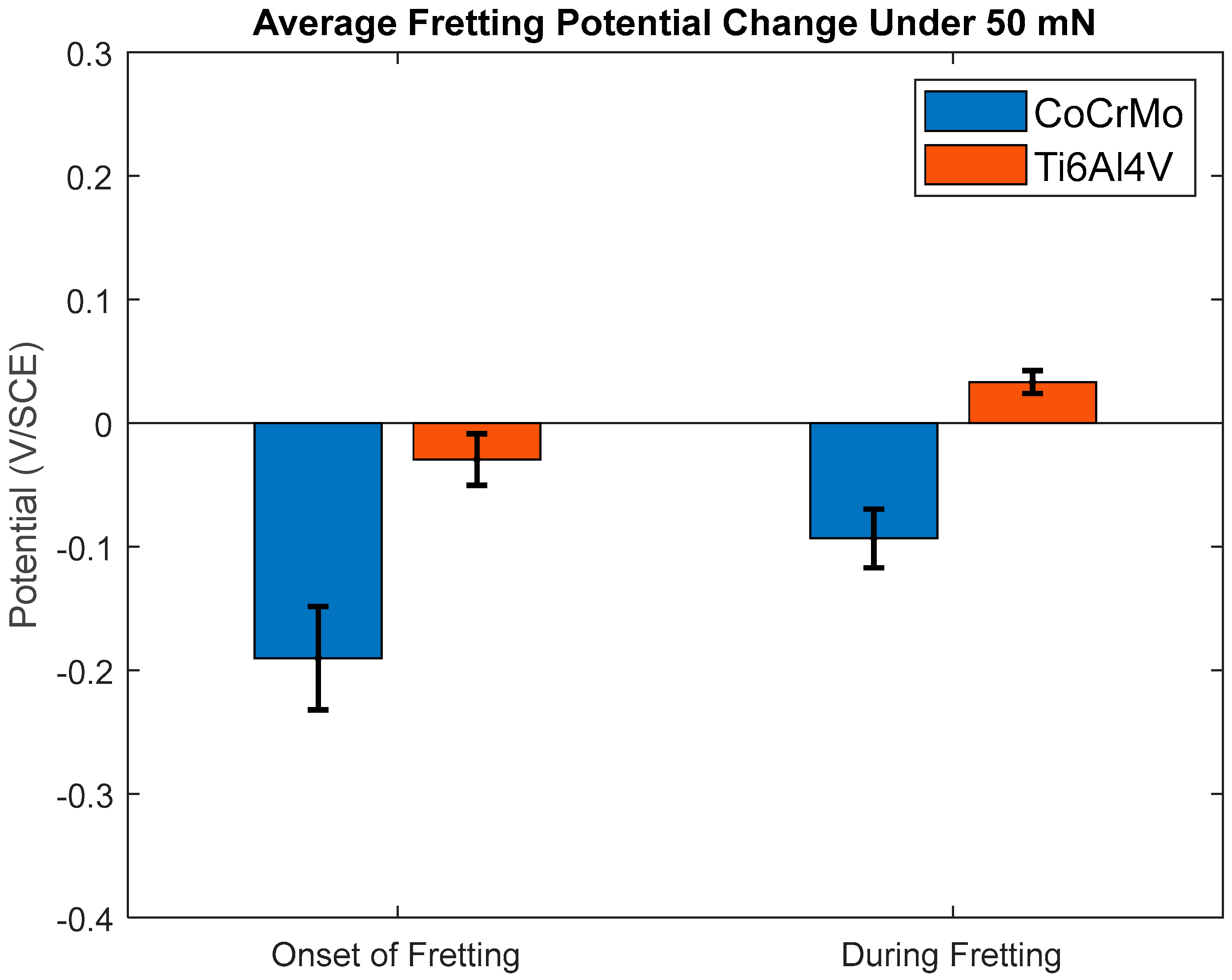
The change in potential was measured with a normal load of 50 mN (corresponds to 0.32 σ y of CoCrMo and 0.29 σ y of Ti6Al4V) before the sliding contact was initiated (dwell), during sliding contact (active articulations), and after sliding motion was ceased (recovery) on CoCrMo and Ti6Al4V as shown in Figure 3, Figure 4 and Figure 5. The potential was monitored until stabilized. After a 1 h dwell period, the reciprocating motion of the spherical slider was applied at 50 mN of the normal load. There was a significant potential drop on the CoCrMo surface immediately after the sliding contact was initiated. The frictional contact on the CoCrMo surface damaged the protective oxide layer and exposed the metal subsurface to a PBS solution. However, the potential drop on the Ti6Al4V surface was relatively insignificant. The average potential drop by sliding contact is compared in Figure 3 and Figure 5. It is evident that the potential of Ti6Al4V instantaneously drops as soon as the slider motion is initiated, but spontaneous repassivation takes place and the potential is gradually recovered to its original potential of the dwell period, while the sliding motion of the slider is continued. It is notable that the presence of the electrolyte is beneficial for titanium to reform the stable oxide layer under light normal contact loads. A small potential drop of Ti6Al4V at 50 mN describes the minimum contact stress to activate an electrochemical reaction is approximately 325 MPa, corresponding to 29% of the yield strength of Ti6Al4V. In contrast, the sliding contact fatigue on CoCrMo continually drops the potential until the sliding motion is ceased. During sliding contact fatigue on the CoCrMo surface, a rapid fluctuation in potential implies a repetition of breakage-reformation of the oxide layer in PBS [24,25,26]. As a result, the porosity of the reformed chromium oxide layer would substantially increase as the frictional contact proceeded. The progressive accumulation of the contact strain also would augment the thermodynamic driving force of surface reactivity in corrosive aqueous environments [30,34]. After sliding motion is ceased, the CoCrMo surface is rapidly repassivated, while Ti6Al4V is readily repassivated even during active sliding contact. Therefore, the Ti6Al4V presented superior oxide chemistry that effectively recovers the oxide layer in the PBS environment by the sliding wear with the 50 mN of normal load.
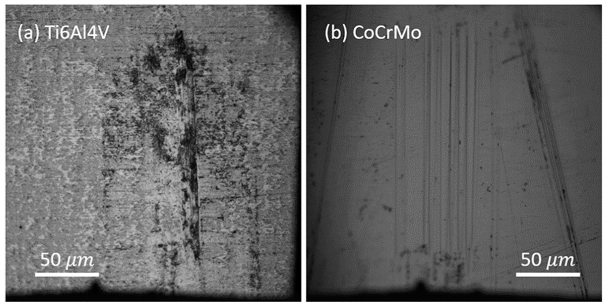
Figure 4 shows the optical microscopic image of the tested areas on both specimen surfaces at the smallest normal load of 50 mN. The frictional contact creates narrow grooves parallel to the sliding direction in the limited area of the tested zone. Through the micro-image inspection, it is not evident that the wear-damaged area is associated with corrosion attacks. However, the open-circuit results presented potential changes that implied the subsequent electrochemistry of the surfaces was activated by mechanical sliding motions. On the Ti6Al4V surface, wear particles produced by adhesion contact were accumulated at the end of the wear track. The rapid oxidation followed by plastic deformation after successive elastic sliding contacts resulted in strain-hardened brittle wear particles. The small wear tracks on CoCrMo resulted from three-body wear by repeating entrainment ejection of wear debris. The progressive plowing of the top layer of chromium oxide produced nano-sized wear debris that adhered on the ceramic slider head and subsequently abraded the surface. The micro-image does not present significant corrosion damages. It may imply the anodic reaction is due to metal ion dissolution and the reformation of the chromium oxide damaged by sliding contact.
The open-circuit potential changes are summarized in Figure 5. The negative change describes oxide layer damage, and therefore, the anodic response is established. As discussed, greater potential drops on CoCrMo are observed upon the onset of sliding contact. The drastic potential drop upon the surface damage is followed by a mild change in potential during successive sliding fatigue. During continuous sliding contact, the negative potential change implies successive metal ion dissolution and oxide regrowth of the CoCrMo surface. The positive change in the potential on the Ti6Al4V surface illustrates that its responsive repassivation produces a mechanically stable oxide layer with considerably low porosity. The reformed oxide layer effectively protects the surface from environmental corrosion. Therefore, the results concluded that the tribocorrosion behaviors of Ti6Al4V would be superior to that of CoCrMo at a small sliding contact load.
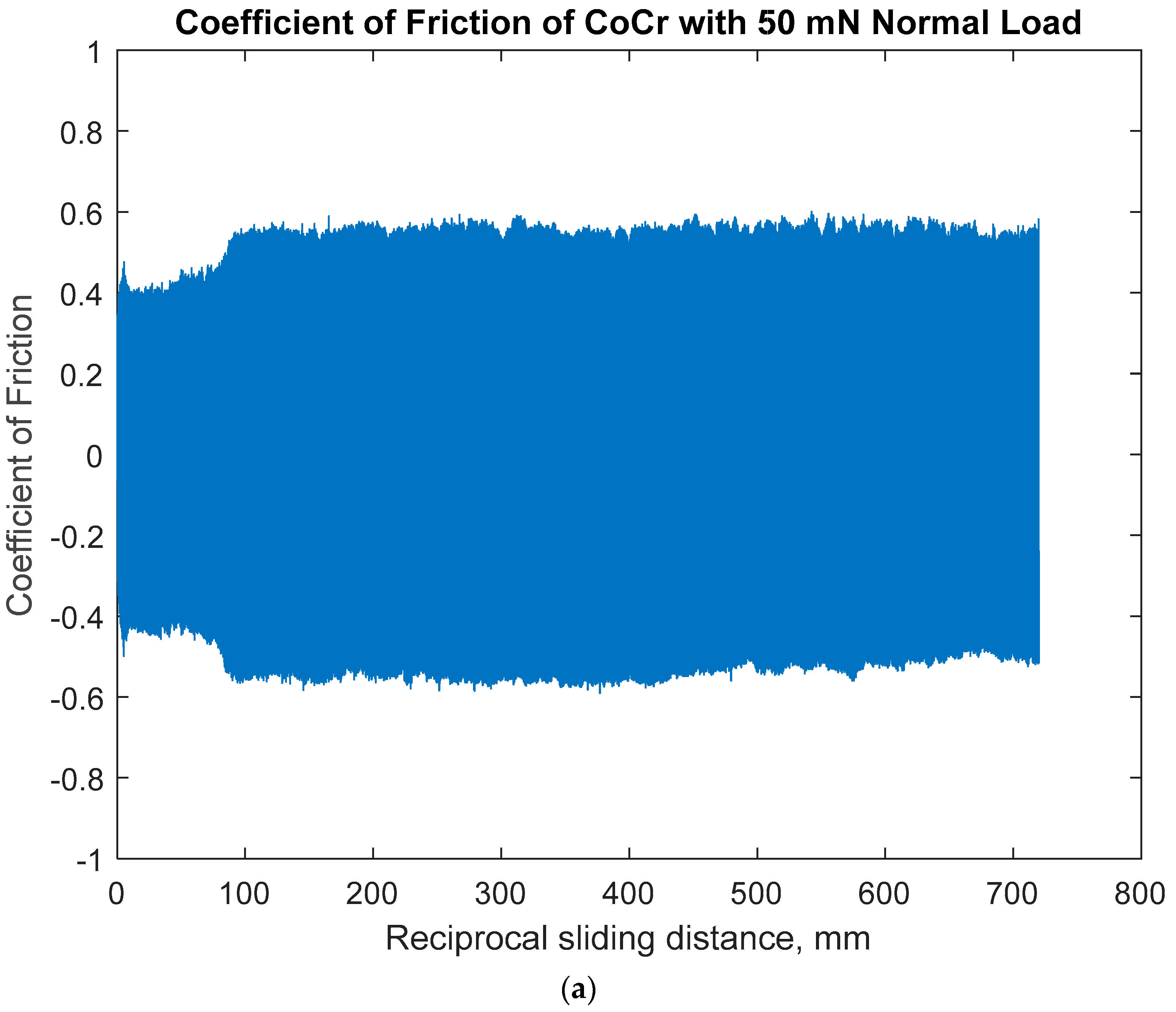
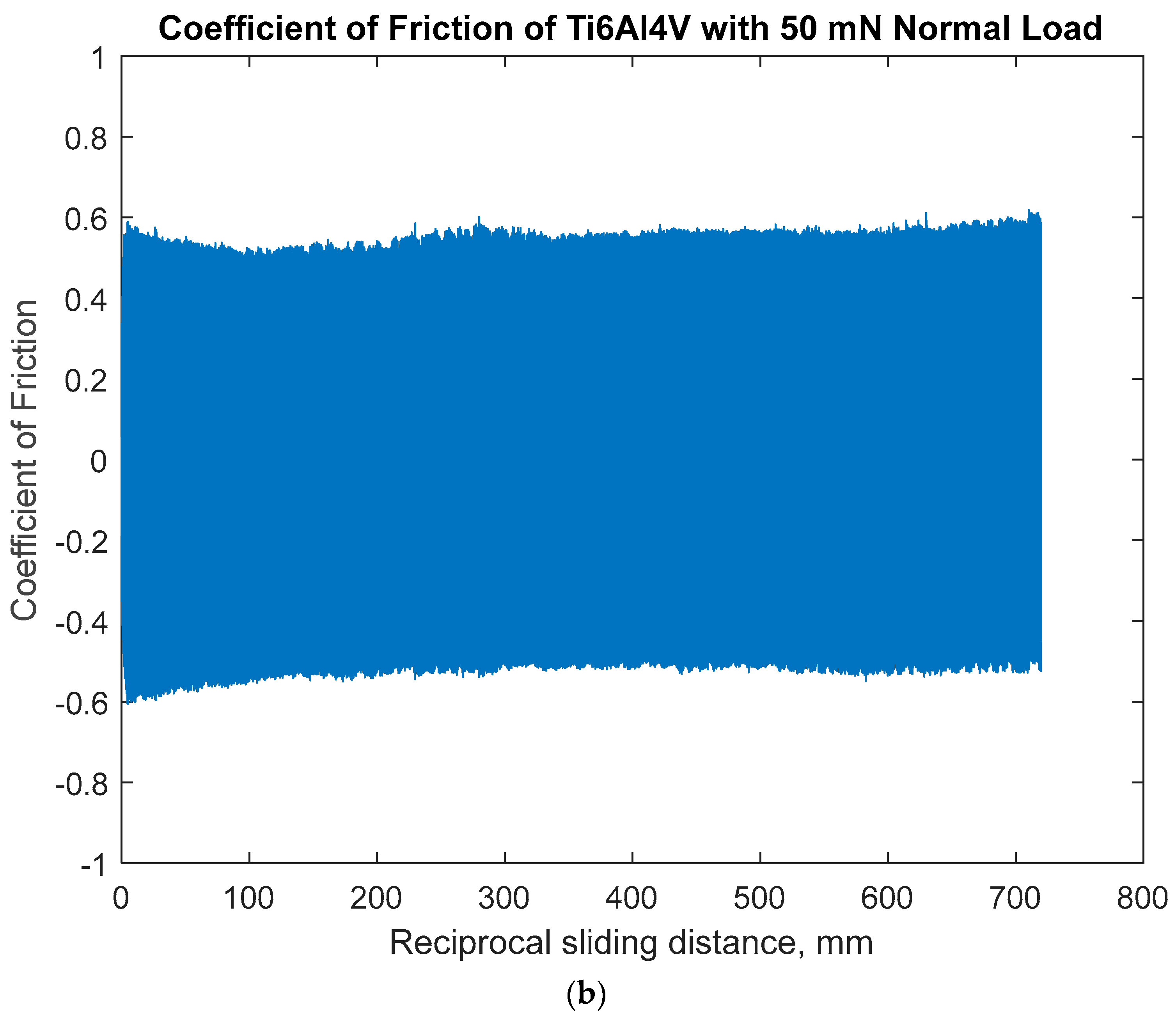
The evolution of the coefficients of friction (COF) monitored during the sliding contact PBS is illustrated in Figure 6. It represents the ratio between the frictional shearing force and the normal loads during the forward and backward motion of the alumina sphere head. The slider motion was controlled at the speed of 12 mm/min and the forward and backward strokes at 200 μ m for an hour (1800 cycles). The COF is closely related to the physical and chemical characteristics of the surface as well as the morphology of the surface including roughness and grain sizes at small-scale contact. In the early stage of the wear test, two surfaces showed different behaviors: the CoCrMo surface initially presented a lower COF of 0.4 and increased up to 0.6 of COF, while the Ti6Al4V surface presented initially 0.6 of COF and slowly decreased after 100 mm of cumulative sliding distance. It would be due to the differences in wear mechanisms: the width of the wear track on Ti6Al4V was greater than that on CoCrMo, and the wear debris of Ti6Al4V were agglomerated; therefore, the wear grooves were bigger than that of CoCrMo. The abrasive wear damage of CoCrMo after 250 reciprocal cycles (100 mm cumulative sliding distance) produced brittle chromium oxide debris that subsequently plowed the damaged surface. The continuous sliding on the Ti6Al4V surface leads to elastic–plastic deformation, and the strain-hardened subsurface layer would promote hardness and reduce the friction coefficient. In both cases, the friction response tended to settle to a stable mechanical process with 50 mN of normal loads. The minor fluctuations in COF for both surfaces suggest that the locally damaged oxide layer may increase adhesive friction, and the repassivation may decrease adhesive force at the interface.

3.1.2. Open-Circuit Potential Under Normal Force 100 mN

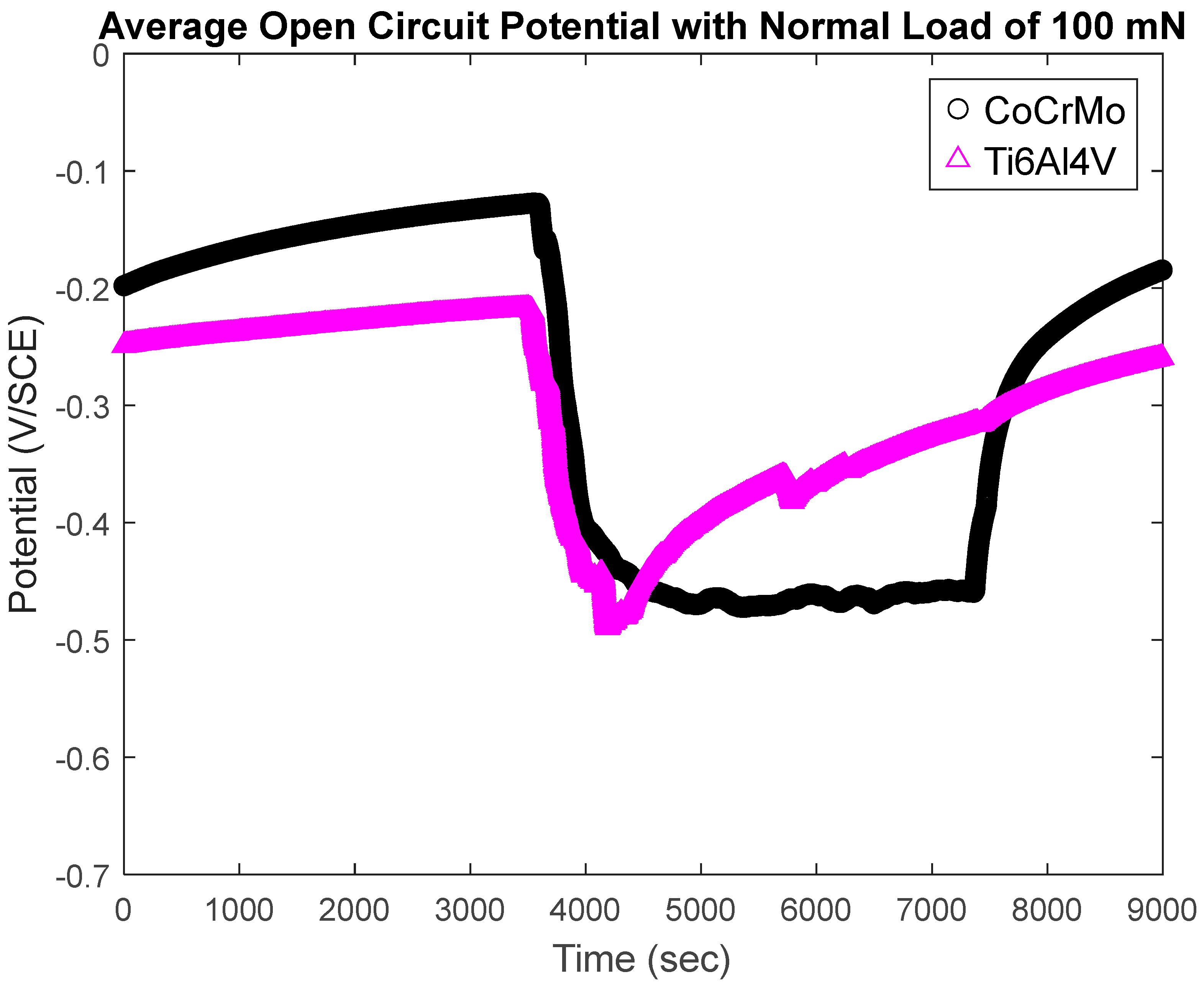
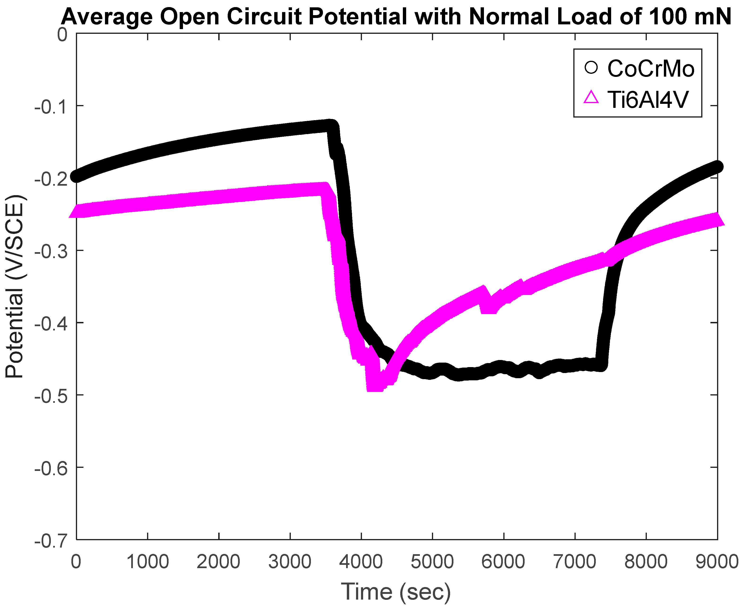
The change in potential was monitored on CoCrMo and Ti6Al4V surfaces at a normal load of 100 mN during three stages including the dwell period, active sliding contact, and after sliding cycles ceased. The potential was allowed to stabilize for 1 h (dwell period) and then the sliding contact was initiated at a 100 mN of normal load. This elastic contact stress by 100 mN of the normal load was approximated by the Hertzian contact theory. The normal load induced contact stresses that corresponded to approximately 0.4 σ y of CoCrMo and 0.36 σ y of Ti6Al4V, respectively. At this greater normal contact load, a rapid potential drop was observed for both surfaces. Figure 7 illustrates substantial oxide layer damages upon the sliding motion. The potential change on Ti6Al4V at 100 mN of normal load presented progressive increase (from negative to zero) in the potential even during active frictional contact. Similarly to the wear experiment with 50 mN, the reformation of the TiO2 layer took place spontaneously. The residual stress developed at the subsurface by frictional contact augments thermodynamic driving forces to reproduce the protective oxide layer. As a result, the rate of oxide layer growth would be greater than the rate of metal ion dissolutions on the Ti6Al4V surface. It clearly illustrates that titanium oxide is capable of spontaneous recovery of the oxide film against corrosion fatigue. The potential change on CoCrMo showed a similar trend as to Ti6Al4V as soon as the sliding contact was initiated. However, during active sliding, the potential was stabilized at a constant level. It may imply that the exposed area of metal matrix by oxide film damage and electrochemical permissibility of the regenerated chromium oxide layer would be consistent. The rate of passive layer recovery on CoCrMo was very immediate when the sliding motion was ceased, while the rate of passivation on Ti6Al4V was continuous from the end of the active reciprocating phase.
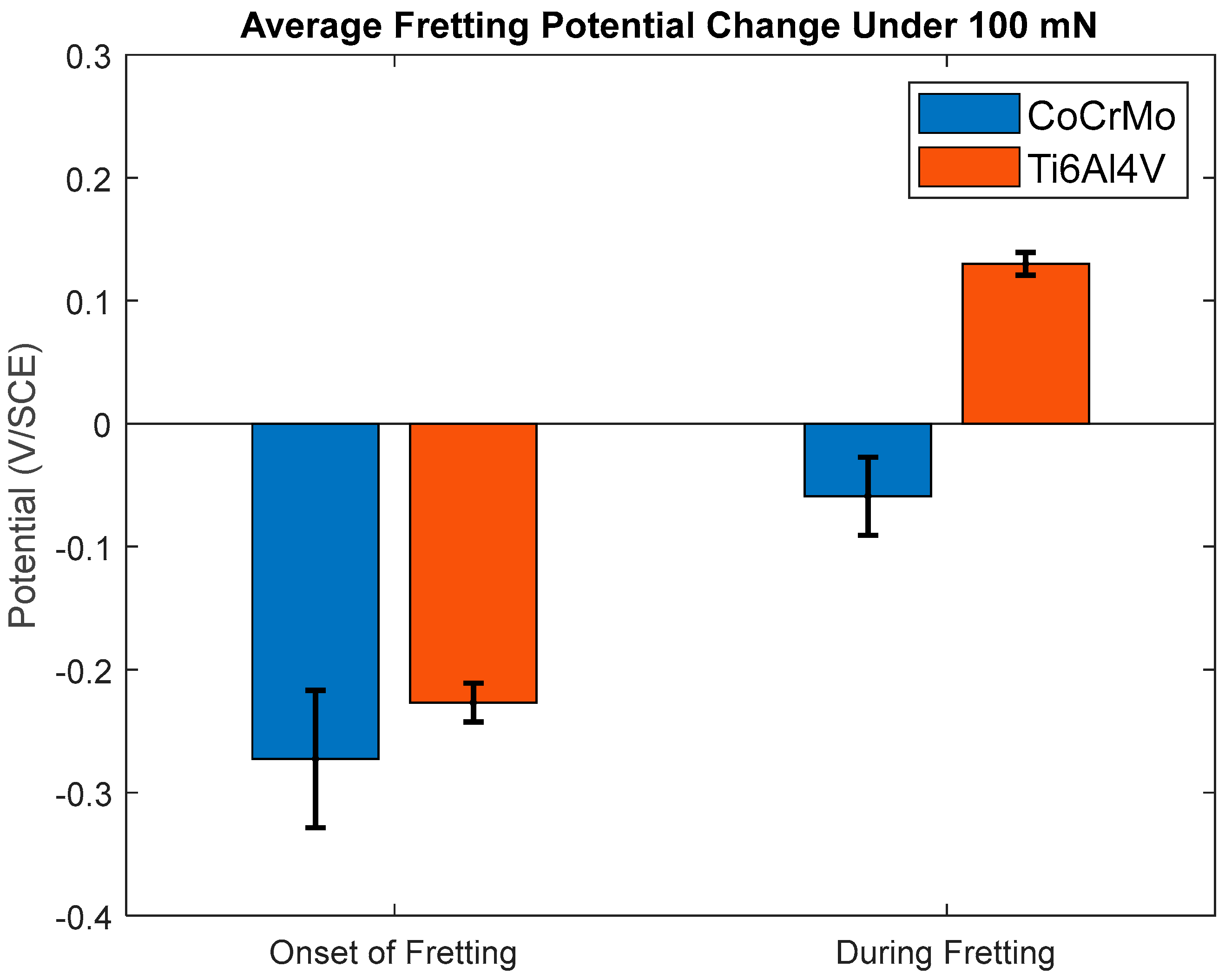
The contact stress on CoCrMo was approximately 30% of its yield strength. The deformation energy by insignificant nominally elastic contact stress was released by the abrasion of the limited depth of CoCr oxide film. As illustrated in Figure 8b, the sliding contact at 100 mN of normal load produced nano-sized wear debris by progressive plowing of the oxide layer and accumulated at the vicinity of the damaged area. Wear particles produced on Ti6Al4V presented a different damage mechanism. The larger agglomerated particles were ceased on the wear track. The wear damage mechanism would be explained by the accumulated elastic stress by adhesion that leads to subsurface delamination. Therefore, the wear particles separated from the surface would be subjected to large-scale plastic deformations by the following cycles of ceramic slider. The corrosion product of the plastically deformed particles would repeat the entrapment and ejection between two surfaces. OCP changes at the onset of sliding fatigue and during the progress of reciprocation are summarized in Figure 9. OCP drops on both CoCrMo and Ti6Al4V were significant when the fretting contact was initiated. However, the capability of oxide layer reformation on Ti6Al4V is much superior to that of CoCrMo during active sliding contact. The positive change in Ti6Al4V illustrated the degree of active repassivation.
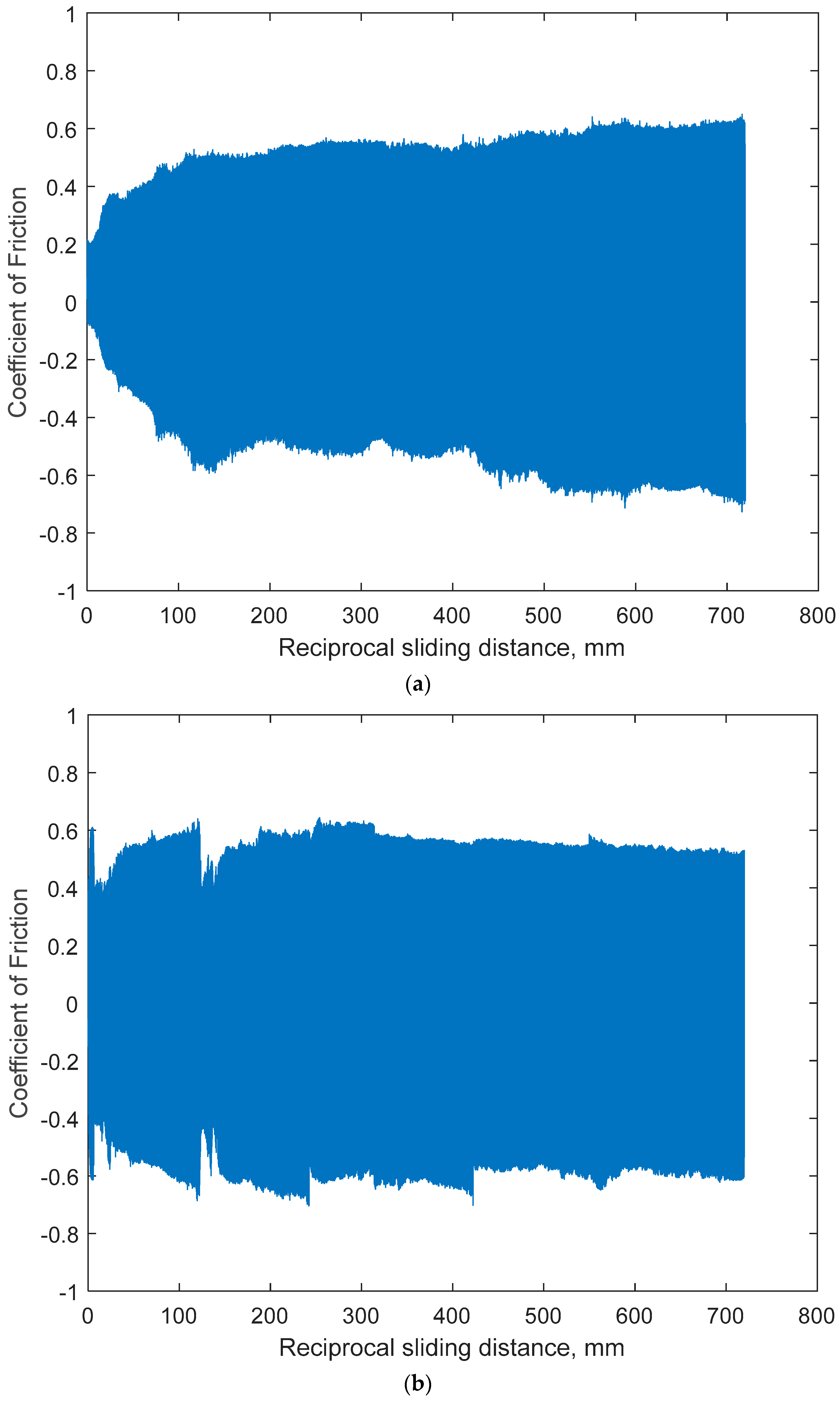
During its cumulated sliding distance, the COF values of CoCrMo surface progressively increased during both forward and backward sliding strokes as shown in Figure 10. However, COF from the Ti6Al4V surface illustrated more fluctuational behaviors at the early stage of the sliding test up to 250 mm (625 cycles). This fluctuation would be induced by the seizure and ejection of wear particles. As discussed in the micromorphologies on the damaged area, the result suggests that the dynamic changes in COF on both surfaces is due to the greater wear depth by larger normal load (100 mN). Therefore, the result describes that during the early sliding cycles, the mechanical loading significantly initiated electrochemical response, and during the following cycles the recovered oxide layer stabilized the tribological response of the Ti6Al4V surface.

3.1.3. Open-Circuit Potential Under Normal Force of 200 mN

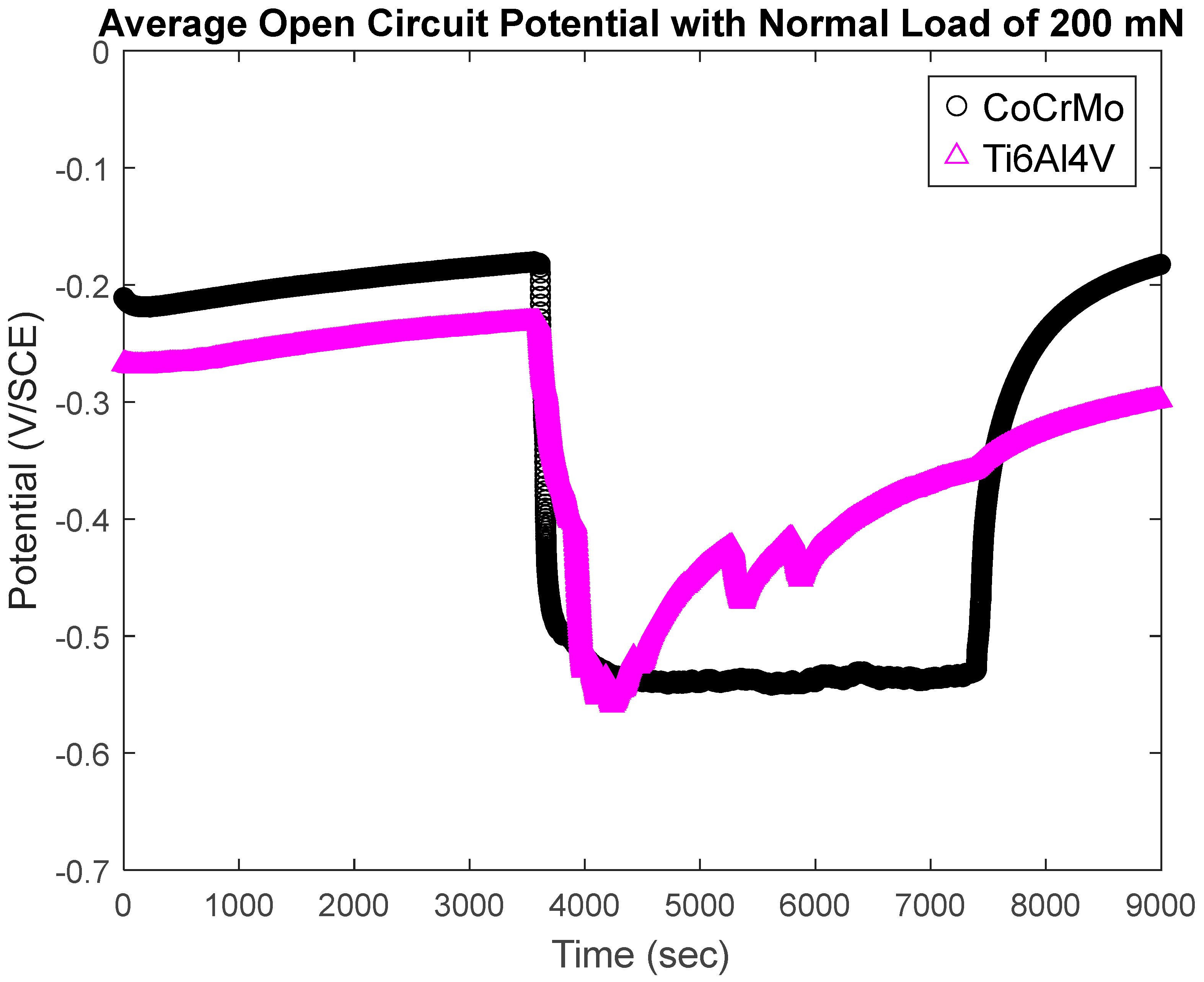
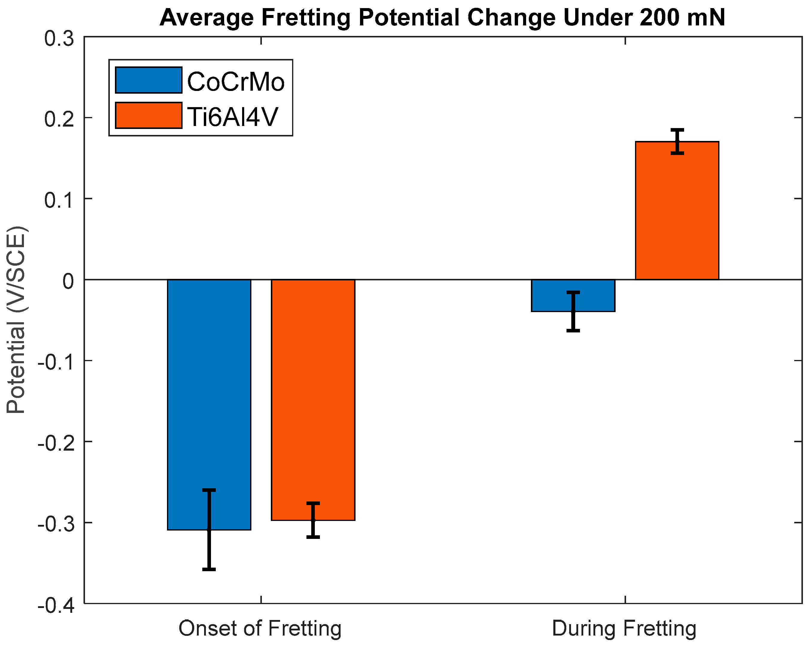
The change in potential was measured with the same parameters as shown in experimental methodology. Three stages of measurements including before the onset of fretting, during active fretting, and after fretting motion stops were conducted on the CoCrMo and Ti6Al4V surfaces with the normal load of 200 mN. The potential changes are depicted in Figure 11. The OCP responses on both CoCrMo and Ti6L4V at 200 mN were very similar to those at 200 mN in general. A large potential drop was obtained as soon as fretting contact was initiated. With different initial OCP before fretting started, all the measured potential levels upon the fretting were mostly the same level at −0.56 V. During the active fretting motions, potentials on CoCrMo were stable with minor fluctuations until the fretting motion was ceased. Similarly, a potential drop on Ti6Al4V was initiated upon the fretting motion. However, during the continuous fretting, the potential increased rapidly and gradually with time. There were several significant changes in OCP on Ti6Al4V. It may be because of the fatigue delamination of the surface layer due to continuous fretting contact. Subsurface cracks would progressively grow during cyclic frictional forces and reach a critical length. The plastically deformed surface layer were flaked from subsequent sliding and the layer was separated from the surface. The drastic potential drops during fretting took place when the delaminated wear particle was produced. However, the desirable nature of oxidative recovery on the Ti6Al4V surface gradually increased the potential as the secure oxide film was formed.
The microscopic inspection of the damaged area as shown in Figure 12 illustrated wear tracks due to large particles sliding on the Ti6Al4V surface. The morphology of the damaged area on CoCrMo with 200 mN of normal force was similar to that with 100 mN of normal loads. The nano-sized wear particles promoted the progressive oxidative wear process on chromium oxide, while the dark area of Ti6Al4V presented a large scale of plastic deformation and an abrasive wear of the subsurface layer. The unstable COF and OCP responses on Ti6Al4V may be described as contact fatigue damage as illustrated in the delamination wear theory by Suh [35]. The wear debris were subjected to large-scale plastic deformation and oxidation that resulted in agglomerated hard and brittle wear particles. During the following mechanical loadings, the brittle debris may induce third-body friction.
Figure 13 shows the OCP changes during the dwell and active sliding processes. As presented in the results with 100 mN, a dramatic potential drop was observed when the sliding contact was initiated on both CoCrMo and Ti6AL4V surfaces. However, the positive potential obtained on Ti6Al4V described the spontaneous repassivation of titanium oxide even during active sliding contact. The oxidation chemistry on the Ti6Al4V surface triggered by continuous mechanical stimuli resulted in the prompt recovery of the passive layer with higher normal loads at 200 mN.
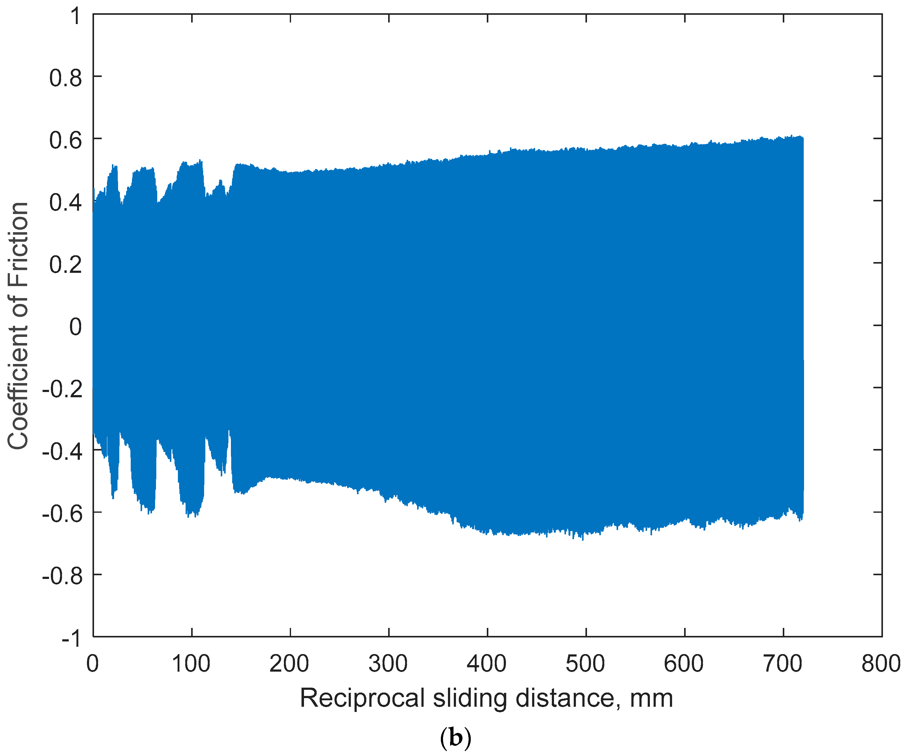
However, friction responses are significantly modified with an increased normal load as can be seen in Figure 14. COF values on CoCrMo instantaneously reached a steady level of COF, approximately 0.5. Throughout the sliding process, COF values on CoCrMo presented stable and constant. The nano debris progressively produced by reciprocal slider motions without complete spalling of the oxide layer. However, the unstable COF changes on Ti6Al4V are because of delamination wear by repeated nominally elastic strains and accumulated dislocations. The process may produce subsurface cracks and their extensions parallel to the interface between the oxide film and metal matrix. While the evolution of OCP and COF on Ti6Al4V during microcracking would not be sensible, when the fatigue wear separated surface flake, large fluctuations of OCP and COF were detected as shown in Figure 11 and Figure 14. It is evident that the fretting cycles at OCP drops are simultaneous with COF changes.
OCP changes during sliding fatigue under three nominally elastic normal loads illustrated a continuous anodic response on CoCrMo and the spontaneous recovery of the Ti6Al4V surface layer upon sliding damage. Therefore, it concluded that the CoCrMo implants may be subjected to electrochemical attacks during an active biomechanical stimulus. However, the Ti6Al4V would be able to reform the oxide layer effectively and block the electrochemical environment spontaneously. The different tribocorrosion behavior of Ti6Al4V and CoCrMo could be explained as the greater hardness and brittle oxide on CoCrMo prevented the surface from plastic deformation and abrasive wear; therefore, the adhesive contact with the shearing motions of the slider would be the dominant wear mechanism. Slow microcracking due to strain hardening at the subsurface cracks would delay the removal of the surface layer. The greater ductility and plastic strain on Ti6Al4V would promote the thermodynamic driving force to facilitate the secure oxide film.

3.2. Potentiodynamic Polarization Resistance

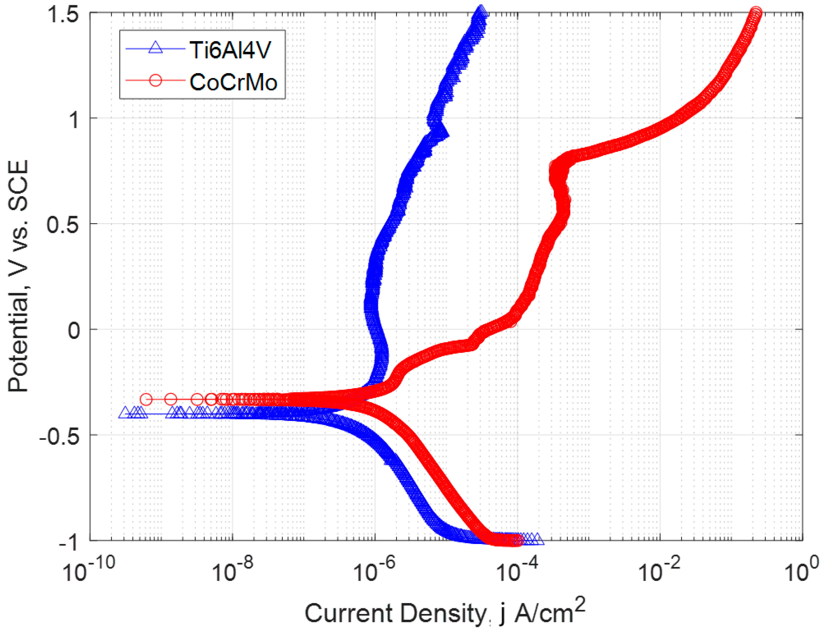
The potentiodynamic response of both metals in PBS without sliding contact was monitored as presented in Figure 15. The polarization curves showed four potential domains including cathodic domain, transition domain, passive domain, and transpassive domain. In the cathodic domain, the current density was due to the reduction in water and partially dissolved oxygen. The transition domain from the cathodic to anodic current took place at the corrosion potential ( E c o r r ) and corrosion current density ( i c o r r ) was obtained. Tafel slopes along the anodic and cathodic branches of the curve were used to determine E c o r r and i c o r r values. The third passive domain corresponded to the passive zone due to oxide formation on the metal surface and where the current density remained stable at the passive current density [36]. The transpassive domain corresponded to the area above the breakdown potential, characterized by the increase in current due to the dissolution of the protective oxide film as well as water oxidation [36].
In order to investigate the stable corrosion protection by surface oxide layers, the potentiondynamic polarization data were analyzed and are summarized in Table 4. They presented clearly dissimilar behaviors in the anodic curve. The passive current of Ti6Al4V is insensitive to potentials, while the passive current of CoCrMo increases with potential. This implies that continuous reformation of TiO2 film during sliding cycles can effectively protect the metal substrate from corrosion attack. However, the oxidation mechanism of the CoCrMo surface illustrates active dissolution of metal ions into the PBS environment.
CoCrMo showed the E c o r r value of −0.331 V which was the same as observed in the OCP measurement before mechanical contact was initiated. For Ti6Al4V, the E c o r r value was −0.401 V. For potential values above +0.75 V, an increase in current density took place. This showed the dissolution of the oxide layer of CoCrMo, whereas for Ti6Al4V, the passive domain was very large and spontaneous, and it did not show a transpassive region at all where the dissolution of the passive film occurred; rather, it stayed in the active–passive zone. CoCrMo was more on the active side than passive and had a transpassive zone where there was only an increase in current after +0.75 V. The i c o r r value of CoCrMo at 1.351 μ A / c m 2 was approximately twice higher than that of Ti6Al4V at 0.722 μ A / c m 2 which signifies that the corrosion rate of CoCrMo is higher in a corrosive aqueous environment [34,37].

3.3. Potentiostatic Polarization Test

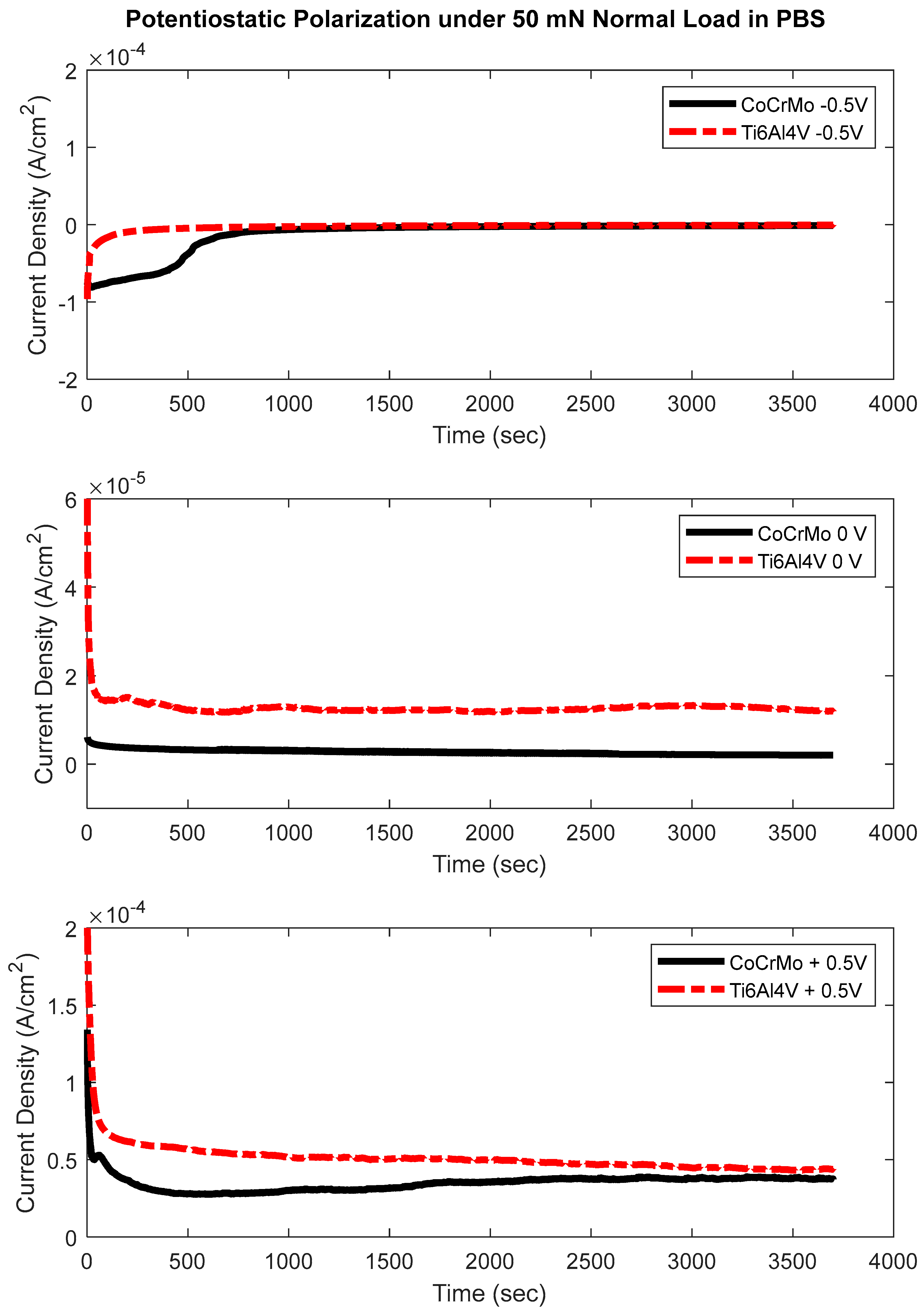
Potentiostatic polarization tests were performed at three potential voltages at −0.5, 0.0, and +0.5 V, applied during active sliding contacts at three normal loads of 50 mN, 100 mN, and 200 mN on both alloys. Figure 16 represents current density change against potentials applied to CoCrMo during sliding fatigue at 50 mN of normal load. During the test, the current settled on a stable value known as the baseline current density (up to 600 s before fretting was initiated). The baseline current would depend upon the surface condition during the time of the test and the electrolyte. However, the current change was not notable due to the sliding motion at 50 mN of normal load on both specimens. This surface traction by the sliding motion would not significantly disturb the oxidation chemistry. This result is in accordance with the micromorphology of the damaged area as illustrated in Figure 4.
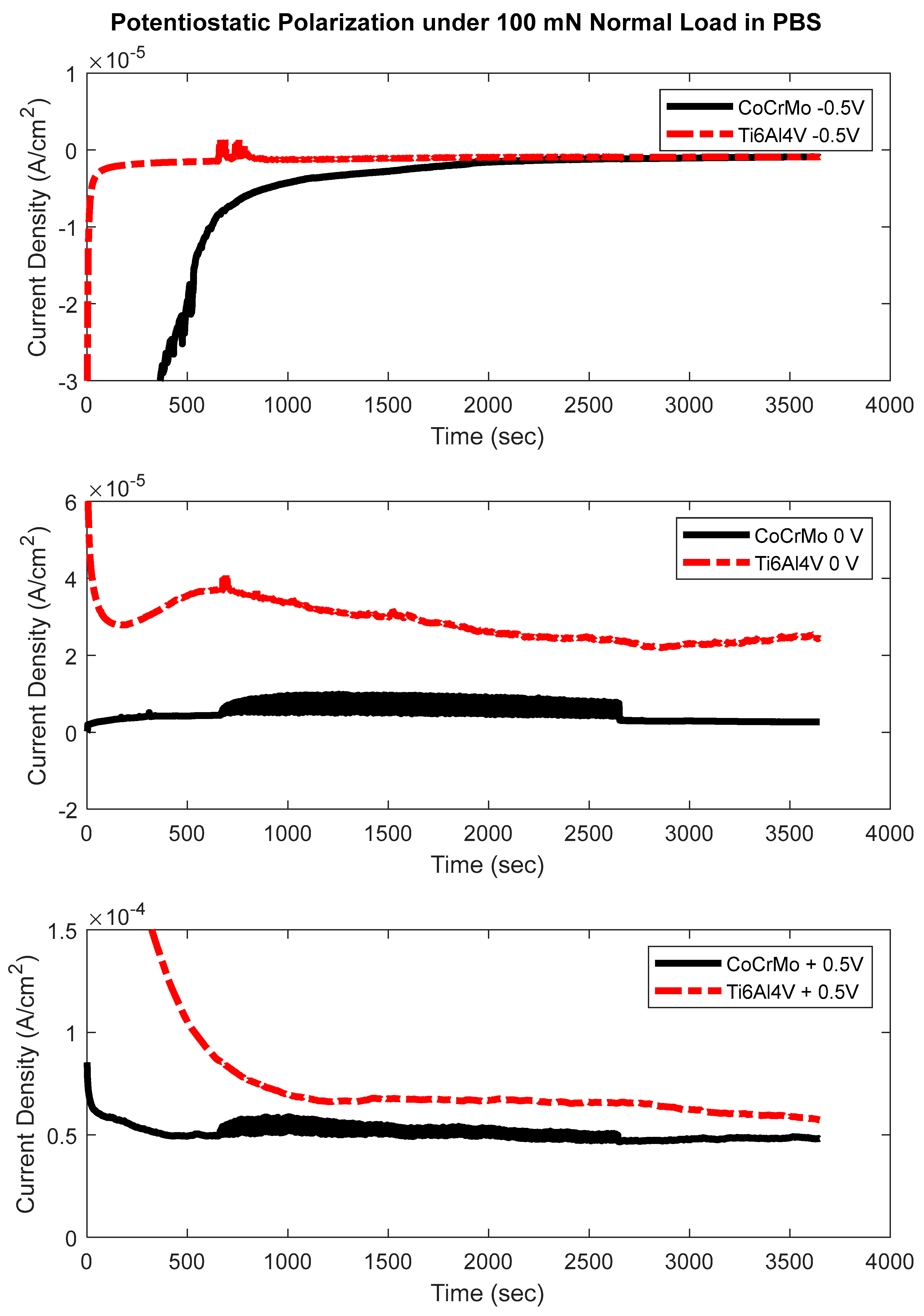
The evolution of current density during sliding contact with 100 mN of normal load is presented in Figure 17. The current density with applied potentials presented electrochemical disturbance at the beginning of sliding contact on the Ti6Al4V surface. Conversely, the current density of CoCrMo illustrated continuous anodic reactions during the course of sliding with zero and positive applied potential. The negative potential on CoCrMo improved corrosion resistance under active mechanical stimuli. On Ti6Al4V, however, without potential and with the positive potential, it is evident that the current density was disturbed instantaneously but settled on a level of a current. This rise in current density on Ti6Al4V indicates the metal dissolutions by the exposure of metal matrix and spontaneous reformation of the oxide layer.
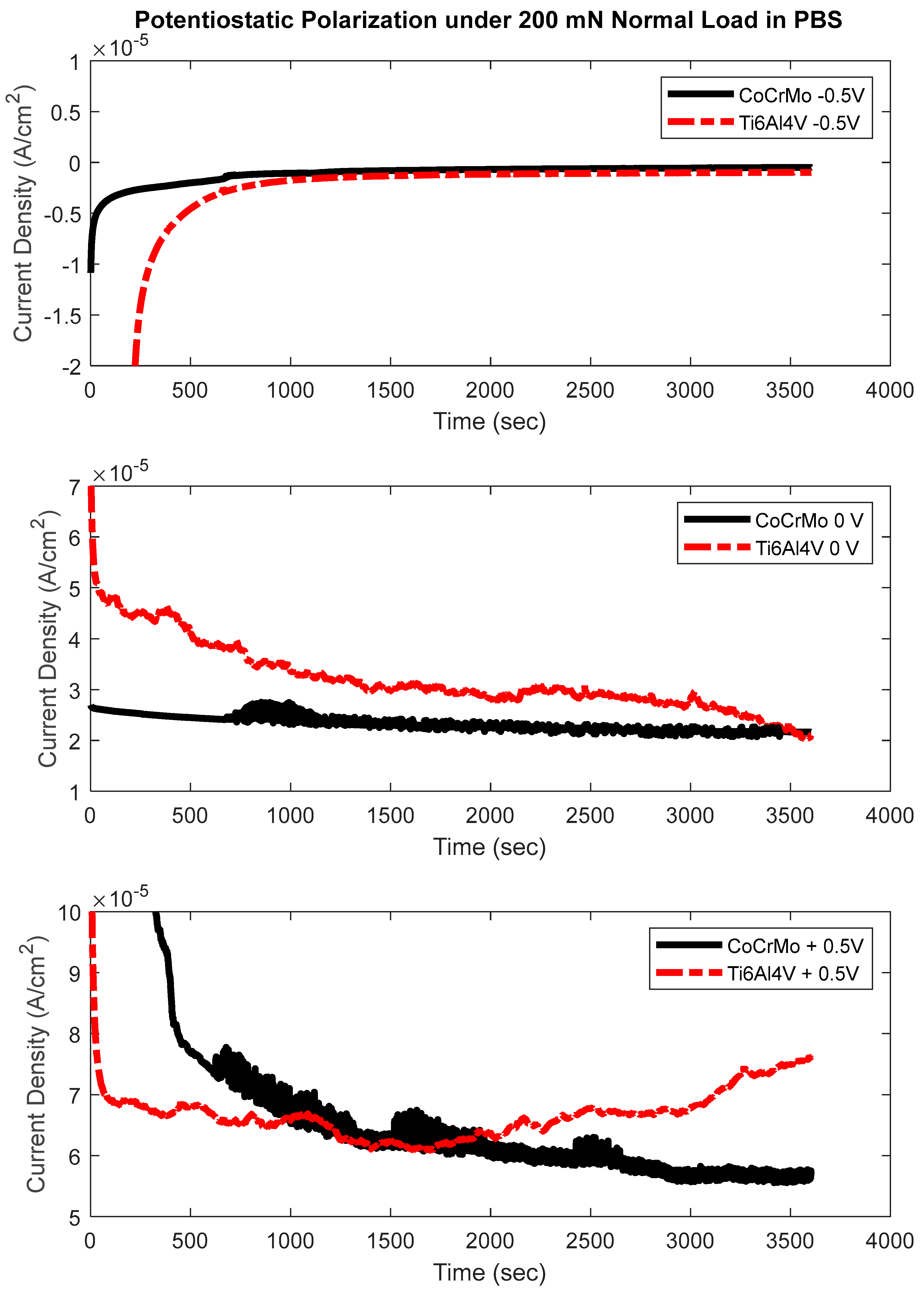
Figure 18 represents current density on CoCrMo change during the highest normal load with 200 mN. Similarly to previous observation with 100 mN of normal load, the baseline current moved from negative values to positive values and settled with a negative potential of −0.5 V. After the initial time for stabilization was allowed, the sliding motion was applied while monitoring current changes. It is more evident on the CoCrMo surface with 200 mN of normal load that the disturbance in current density with positive 0.5 V potential was greater than the current density without potential applied (0.0 V). A series of current density measurement on Ti6Al4V at the same potential values indicated insignificant current change at all potentials. However, with zero and positive potential, the current response of the Ti6Al4V surface showed fluctuation without mechanical contact. The results confirmed that the oxidation chemistry of Ti6Al4V is not sensitive against electrochemical and mechanical stimuli. It may conclude that Ti6Al4V implants would be more stable for a load-bearing orthopedic application.
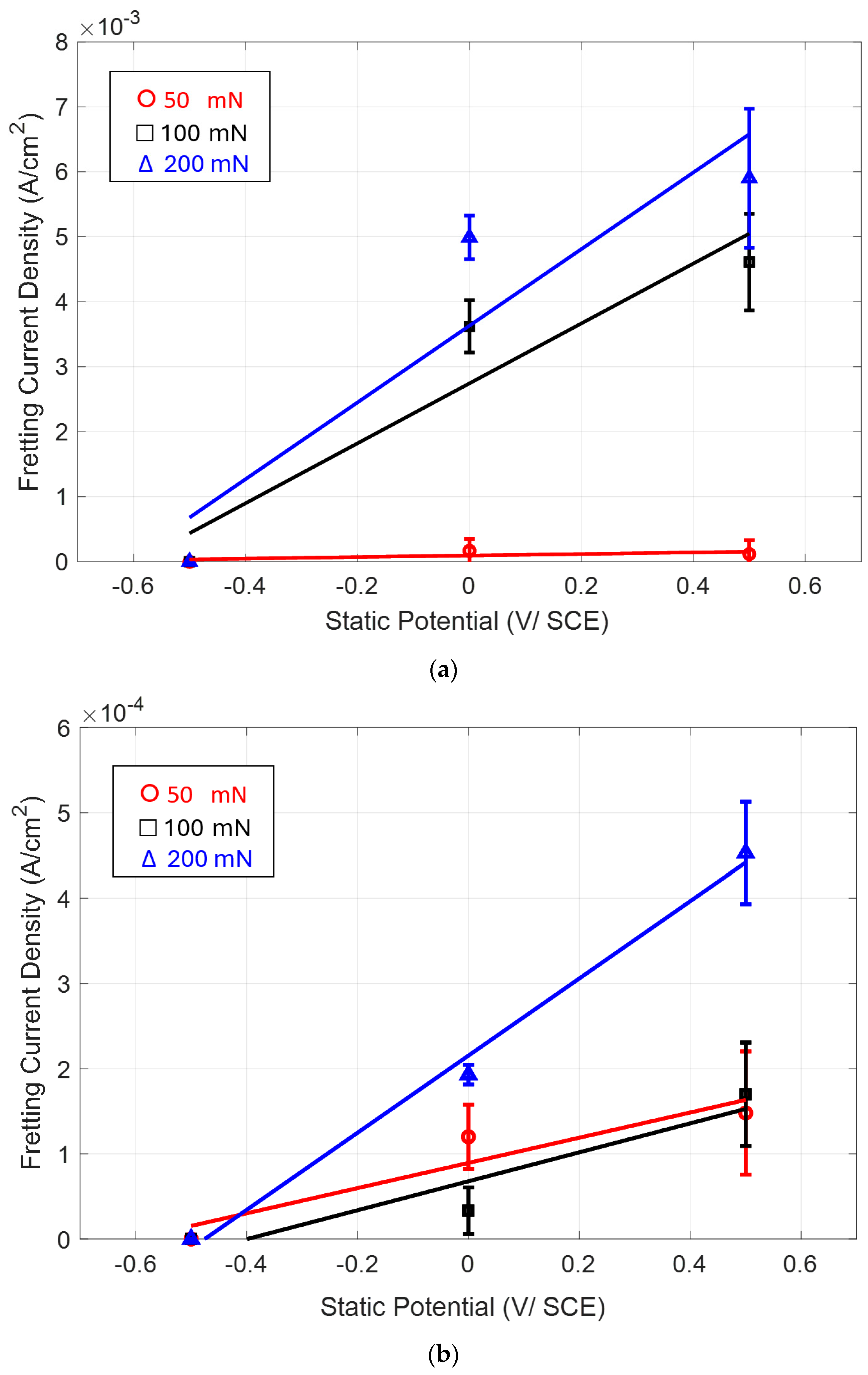
The current density evolution of two surfaces as a function of applied potentials and frictional tractions is summarized in Figure 19. A statistical representation of potentiostatic illustrated that the active anodic dissolution and oxidation took place on the CoCrMo surface with the increase in both potential and tribological loads, while the electrochemical response of Ti6Al4V was stable in the mechanical and chemical combinations. The onset of the significant corrosion damage of CoCrMo with zero and positive potential was observed under 100 mN and 200 mN of normal loads. However, the onset of significant corrosion damage of Ti6Al4V with zero and positive potential was observed only at 200 mN of normal load. Therefore, it concluded that the CoCrMo surface is more sensitive to both tribological and electrochemical stimuli.

4. Conclusions

  • This study compared the modified electrochemical responses on medical grade CoCrMo and Ti6Al4V surfaces when the active sliding fatigue initiated oxide damages. Reciprocal sliding motions were applied at varying normal contact loads in the elastic range to comprehend the multi-factorial behaviors of implant materials utilizing OCP, potentiodynamic polarization, and potentiostatic polarization measurements.
  • The nominally elastic contact stress significantly accelerates electrochemical responses for both implant materials.
  • The wear mechanism of Ti6Al4V in an aqueous environment illustrated that delamination would be the dominant wear process. The following contact cycles plastically deform and agglomerate produced wear particles that are ultimately seized on the damaged area.
  • Nano-sized wear debris on CoCrMo produced during active sliding contact in PBS solution implies that immediate abrasive damage would take place on the brittle Cr oxide film at all normal loads. Wear debris were piled up surrounding the damaged zone.
  • During active sliding, OCP dropped more in CoCrMo at all loads than Ti6Al4V suggesting more accelerated tribocorrosion damage on CoCrMo. OCP data illustrated prompt recovery of the titanium oxide layer that effectively protected metal matrix from anodic reactions.
  • The sliding friction by COF was affected by the combination of anodic potential change and the wear damage processes of both specimens: the larger variation in OCP and COF on Ti6Al4V would be due to the alternating entrapment and ejection of the wear particle.
  • The thermodynamic driving force initiated by cumulated elastic strains on Ti6Al4V played a significant role in establishing electrochemically stable titanium dioxide.
  • The potentiodynamic polarization test results showed a high passive zone for Ti6Al4V. The icorr value was lower by an order of one magnitude suggesting a lower corrosion rate. The spontaneous and wide passive zone of titanium oxide represented less corrosion on higher potential. CoCrMo was more on an active anodic side and had a transpassive region which represents the dissolution of the metal ion in the electrolyte.
  • The potentiostatic test concluded that oxidation chemistry on CoCrMo exhibited more sensitivity at the greater normal loads of 100 mN and 200 mN. Significant electrochemical sensitivity on Ti6Al4V was found only at the highest normal load of 200 mN.
  • This experimental work generally concluded that CoCrMo is more prone to be vulnerable when mechanical stimuli is accompanied with corrosion attacks. Ti6Al4V would be a more durable metallic implant material for the load-bearing orthopedic applications.

Author Contributions

Data curation, E.C., M.V.P.; Formal Analysis, E.C., M.V.P. and J.J.R.; Methodology, E.C., M.V.P. and J.J.R.; Supervision, J.J.R.; Writing—original draft, M.V.P. and J.J.R.; Writing—review and editing, J.J.R. All authors have read and agreed to the published version of the manuscript.

Funding

The research was funded by the Youngstown State University Research Council grant and Center for Excellence program.

Institutional Review Board Statement

Not applicable.

Informed Consent Statement

Not applicable.

Data Availability Statement

The raw data supporting the conclusions of this article will be made available by the authors upon request.

Acknowledgments

The Authors gratefully acknowledge the financial support of the University Research Council grant and Center for Excellence program at Youngstown State University.

Conflicts of Interest

The authors declare no conflicts of interest.

References

  1. Morlock, M.M.; Hube, R.; Wassilew, G.; Prange, F.; Huber, G.; Perka, C. Taper corrosion: A complication of total hip arthroplasty. EFORT Open Rev. 2020, 5, 776–784. [Google Scholar] [CrossRef] [PubMed]
  2. Nečas, D.; Usami, H.; Niimi, T.; Sawae, Y.; Krupka, I.; Hartl, M. Running-in friction of hip joint replacements can be significantly reduced: The effect of surface-textured acetabular cup. Friction 2020, 8, 1137–1152. [Google Scholar] [CrossRef]
  3. Martin, R.B.; Burr, D.B.; Sharkey, N.A.; Fyhrie, D.P. Skeletal Tissue Mechanics; Springer: New York, NY, USA, 2015. [Google Scholar]
  4. Hallab, N.; Jacobs, J. Orthopedic Implant Fretting Corrosion. Corros. Rev. 2003, 21, 183–214. [Google Scholar] [CrossRef]
  5. Couto, M.; Vasconcelos, D.; Sousa, D.M.; Sousa, B.; Conceição, F.; Neto, E.; Lamghari, M.; Alves, C.J. The Mechanisms Underlying the Biological Response to Wear Debris in Periprosthetic Inflammation. Front. Mater. 2020, 7, 274. [Google Scholar] [CrossRef]
  6. Zhu, J.; Xu, N.; Zhang, C. Characteristics of copper corrosion in simulated uterine fluid in the presence of protein. Adv. Contracept. 1999, 15, 179–190. [Google Scholar] [CrossRef]
  7. Liu, Y.; Gilbert, J.L. The effect of simulated inflammatory conditions and pH on fretting corrosion of CoCrMo alloy surfaces. Wear 2017, 390–391, 302–311. [Google Scholar] [CrossRef]
  8. Rebenda, D.; Vrbka, M.; Cípek, P.; Toropitsyn, D.; Necas, D.; Pravda, M.; Hart, M. On the Dependence of Rheology of Hyaluronic Acid Solutions and Frictional Behavior of Articular Cartilage. Materials 2020, 13, 2659. [Google Scholar] [CrossRef]
  9. Moharrami, N.; Langton, D.; Sayginer, O.; Bull, S. Why does titanium alloy wear cobalt chrome alloy despite lower bulk hardness: A nanoindentation study? Thin Solid Film. 2013, 549, 79–86. [Google Scholar] [CrossRef]
  10. Mihalko, W.M.; Haider, H.; Kurtz, S.; Marcolongo, M.; Urish, K. New materials for hip and knee joint replacement: What’s hip and what’s in kneed? J. Orthop. Res. 2019, 38, 1436–1444. [Google Scholar] [CrossRef]
  11. Park, J.B.; Lakes, R.S. Biomaterials: An Introduction; Springer: New York, NY, USA, 2007. [Google Scholar]
  12. Langton, D.J.; Sidaginamale, R.; Lord, J.K.; Nargol, A.V.F.; Joyce, T.J. Taper junction failure in large-diameter metal-on-metal bearings. Bone Jt. Res. 2012, 1, 56–63. [Google Scholar] [CrossRef]
  13. Compte, P. Metallurgical observations of Biomaterials. In Contemporary Biomaterials; Boretos, J.W., Eden, M., Eds.; Noyes Publications: Park Ridge, NJ, USA, 1984. [Google Scholar]
  14. Tardelli, J.D.C.; Bolfarini, C.; dos Reis, A.C. Comparative analysis of corrosion resistance between beta titanium and Ti-6Al-4V alloys: A systematic review. J. Trace Elem. Med. Biol. 2020, 62, 126618. [Google Scholar] [CrossRef]
  15. ASTM International. Standard Terminology Relating to Wear and Erosion. In Annual Book of Standards; ASTM: West Conshohocken, PA, USA, 1987; Volume 3, pp. 243–250. [Google Scholar]
  16. Lipsitt, H.A.; Wang, D.Y. The effects of interstitial solute atoms on the fatigue limit behavior of titanium. Trans. AIME 1961, 221, 918. [Google Scholar]
  17. Sonntag, R.; Reinders, J.; Gibmeier, J.; Kretzer, J.P. Fatigue Performance of Medical Ti6Al4V Alloy after Mechanical Surface Treatments. PLoS ONE 2015, 10, e0121963. [Google Scholar] [CrossRef] [PubMed]
  18. Ratner, B.D. Biomaterials Science: An Introduction to Materials in Medicine; Elsevier, Academic Press: Amsterdam, The Netherlands, 2011. [Google Scholar]
  19. Oungoulian, S.R.; Durney, K.M.; Jones, B.K.; Ahmad, C.S.; Hung, C.T.; Ateshian, G.A. Wear and damage of articular cartilage with friction against orthopedic implant materials. J. Biomech. 2015, 48, 1957–1964. [Google Scholar] [CrossRef] [PubMed]
  20. Gilbert, J.L. Electrochemical behavior of metals in the biological milieu. In Comprehensive Biomaterials; Healy, K.E., Ducheyne, P., Kirkpatrick, C.J., Eds.; Elsevier Press: Amsterdam, The Netherlands, 2011; Chapter 13. [Google Scholar]
  21. Hatamleh, M.M.; Wu, X.; Alnazzawi, A.; Watson, J.; Watts, D. Surface characteristics and biocompatibility of cranioplasty titanium implants following different surface treatments. Dent. Mater. 2018, 34, 676–683. [Google Scholar] [CrossRef]
  22. Wimmber, M.A.; Radice, S.; Janssen, D.; Fischer, A. Fretting-corrosion of CoCr-alloys against Ti6Al4V: The importance of molybdenum in oxidative biological environments. Wear 2021, 477, 203813. [Google Scholar] [CrossRef]
  23. Quiram, G.; Gindri, I.M.; Kerwell, S.; Shull, K.; Mathew, M.T.; Rodrigues, D.C. Nanoscale Mechanical Evaluation of Electrochemically Generated Tribolayer on CoCrMo Alloy for Hip Joint Application. J. Bio- Tribo-Corros. 2016, 2, 15. [Google Scholar] [CrossRef]
  24. Sasikumar, Y.; Indira, K.; Rajendran, N. Surface Modification Methods for Titanium and Its Alloys and Their Corrosion Behavior in Biological Environment: A Review. J. Bio- Tribo-Corros. 2019, 5, 36. [Google Scholar] [CrossRef]
  25. Baragetti, S.; Villa, F. Corrosion Fatigue of High-Strength Titanium Alloys under Different Stress Gradients. J. Miner. Met. Mater. Soc. 2015, 67, 1154–1161. [Google Scholar] [CrossRef]
  26. Beevers, C.J.; Robinson, J.L. Some observations on the influence of oxygen content on the fatigue behavior of α-titanium. J. Less Common Met. 1969, 17, 345–352. [Google Scholar] [CrossRef]
  27. Posada, O.M.; Tate, R.J.; Meek, R.D.; Grant, M.H. In Vitro Analyses of the Toxicity, Immunological, and Gene Expression Effects of Cobalt-Chromium Alloy Wear Debris and Co Ions Derived from Metal-on-Metal Hip Implants. Lubricants 2015, 3, 539–568. [Google Scholar] [CrossRef]
  28. Chandra, A.; Ryu, J.; Karra, P.; Shrotriya, P.; Weik, T. Electrochemical dissolution of biomedical grade Ti6Al4V: Influence of stress and environment. CIRP Ann. 2009, 58, 499–502. [Google Scholar] [CrossRef]
  29. Ryu, J.; Shrotriya, P. Mechanical load assisted dissolution response of biomedical cobalt–chromium and titanium metallic alloys: Influence of in-plane stress and chemical environment. Wear 2015, 332–333, 662–668. [Google Scholar] [CrossRef]
  30. Ryu, J.J.; Shrotriya, P. Influence of roughness on surface instability of medical grade cobalt–chromium alloy (CoCrMo) during contact corrosion–fatigue. Appl. Surf. Sci. 2013, 273, 536–541. [Google Scholar] [CrossRef]
  31. Ryu, J.; Letchuman, S.; Shrotriya, P. Roughness evolution of metallic implant surfaces under contact loading and nanometer-scale chemical etching. J. Mech. Behav. Biomed. Mater. 2012, 14, 55–66. [Google Scholar] [CrossRef]
  32. Chattopadhyay, R. Surface Wear—Analysis, Treatment, and Prevention; ASM International: Materials Park, OH, USA, 2001. [Google Scholar]
  33. Kumar, S.; Sivakumar, B.; Narayanan, T.S.; Raman, S.G.S.; Seshadri, S.K. Fretting-corrosion mapping of CP-Ti in Ringer’s solution. Wear 2010, 268, 1537–1541. [Google Scholar] [CrossRef]
  34. Alemón, B.; Flores, M.; Ramírez, W.; Huegel, J.C.; Broitman, E. Tribocorrosion behavior and ions release of CoCrMo alloy coated with a TiAlVCN/CNx multilayer in simulated body fluid plus bovine serum albumin. Tribol. Int. 2015, 81, 159–168. [Google Scholar] [CrossRef]
  35. Flemming, J.R.; Suh, N.P. Mechanics of crack propagation in delamination wear. Wear 1977, 44, 9–56. [Google Scholar] [CrossRef]
  36. Mellado-Valero, A.; Muñoz, A.; Pina, V.; Sola-Ruiz, M. Electrochemical Behaviour and Galvanic Effects of Titanium Implants Coupled to Metallic Suprastructures in Artificial Saliva. Materials 2018, 11, 171. [Google Scholar] [CrossRef]
  37. Mitchell, A.; Shrotriya, P. Mechanical load-assisted dissolution of metallic implant surfaces: Influence of contact loads and surface stress state. Acta Biomater. 2008, 4, 296–304. [Google Scholar] [CrossRef]
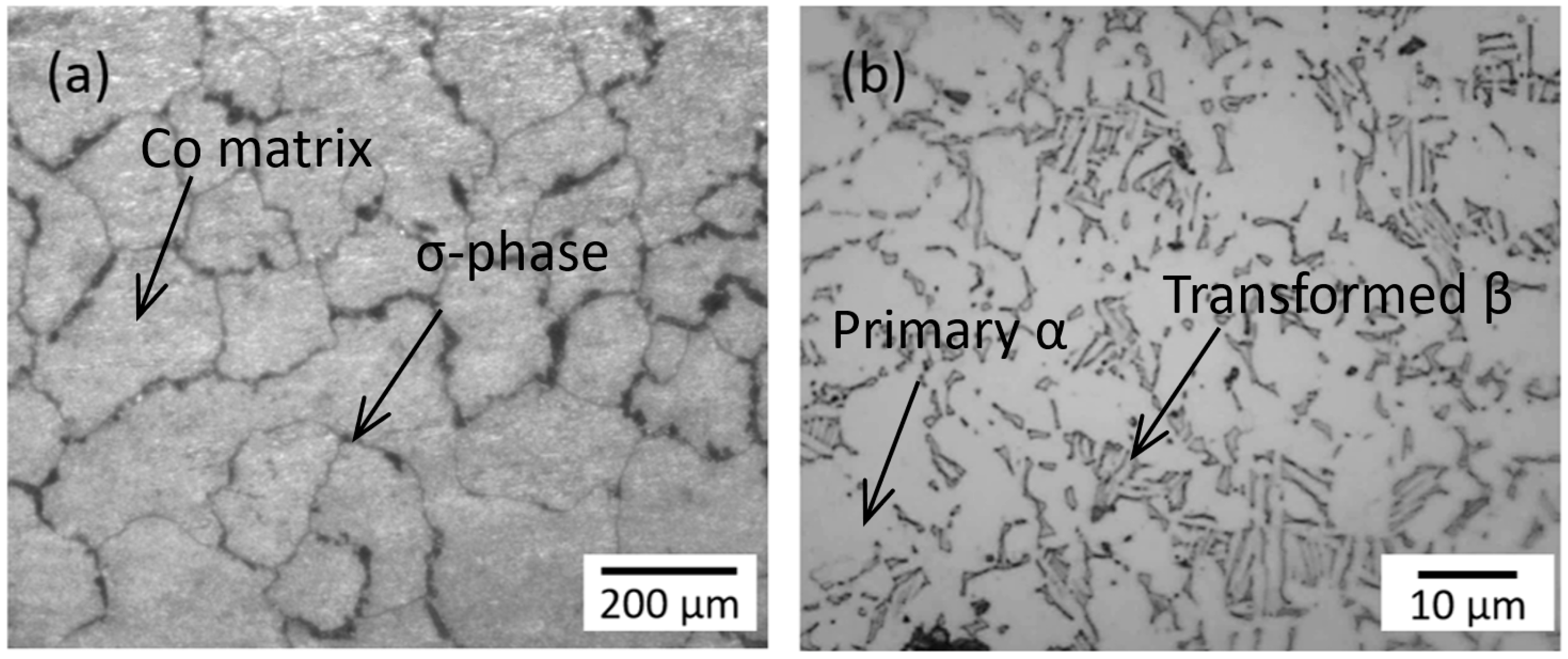
Figure 1. Microstructures of (a) CoCrMo and (b) Ti6Al4V.
Lubricants 12 00437 g001
Figure 2. (a) Schematic of a tribocorrosion experimental set up that consists of a nanoscale tribometer and an electrochemical bath; (b) specimen prepared in epoxy and custom-built liquid bath.
Lubricants 12 00437 g002
Figure 3. OCP change on Ti6Al4V and CoCrMo at 50 mN of normal load.
Lubricants 12 00437 g003
Figure 4. Optical microscope image at 50 mN; (a) Ti6Al4V and (b) CoCrMo.
Lubricants 12 00437 g004
Figure 5. Average OCP change in CoCrMo and Ti6Al4V at 50 mN of normal load.
Lubricants 12 00437 g005
Figure 6. COF change on (a) CoCrMo and (b) Ti6Al4V at 50 mN of normal load in PBS.
Lubricants 12 00437 g006aLubricants 12 00437 g006b
Figure 7. OCP change on Ti6Al4V and CoCrMo at 100 mN of normal load.
Lubricants 12 00437 g007
Figure 8. Optical microscope image at 100 mN; (a) Ti6Al4V and (b) CoCrMo.
Lubricants 12 00437 g008
Figure 9. Average OCP change in CoCrMo and Ti6Al4V at 100 mN.
Lubricants 12 00437 g009
Figure 10. COF change on (a) CoCrMo and (b) Ti6Al4V at 100 mN of normal load in PBS.
Lubricants 12 00437 g010
Figure 11. OCP change on Ti6Al4V and CoCrMo at 200 mN of normal load.
Lubricants 12 00437 g011
Figure 12. Optical microscope image at 200 mN; (a) Ti6Al4V and (b) CoCrMo.
Lubricants 12 00437 g012
Figure 13. Average OCP change in CoCrMo and Ti6Al4V at 200 mN of normal load.
Lubricants 12 00437 g013
Figure 14. COF change on (a) CoCrMo and (b) Ti6Al4V at 200 mN of normal load in PBS.
Lubricants 12 00437 g014aLubricants 12 00437 g014b
Figure 15. Potentiodynamic polarization resistance (PPR) of CoCrMo and Ti6Al4V.
Lubricants 12 00437 g015
Figure 16. Potentiostatic polarization with sliding contact at 50 mN of normal loading.
Lubricants 12 00437 g016
Figure 17. Potentiostatic polarization with sliding contact at 100 mN of normal loading.
Lubricants 12 00437 g017
Figure 18. Potentiostatic polarization with sliding contact at 200 mN of normal loading.
Lubricants 12 00437 g018
Figure 19. Current density of (a) CoCrMo and (b) Ti6Al4V with applied static potentials and sliding contact.
Lubricants 12 00437 g019
Table 1. Chemical compositions of specimens.
Ti6Al4V (F136)
C (%)N (%)O (%)Fe (%)Al (%)V (%)Ti
0.032 ± 0.010.0063 ± 0.0010.12 ± 0.010.18 ± 0.0654.67 ± 1.723.95 ± 0.11Balance
CoCrMo (F1537)
C (%)Si (%)Mn (%)Ni (%)Cr (%)Mo (%)Fe (%)N (%)Co
0.05 ± 0.010.59 ± 0.0050.748 ± 0.1050.133 ± 0.08327.52 ± 0.4395.59 ± 0.150.198 ± 0.0390.168 ± 0.004Balance
Table 2. Characterization of implant specimens.
Materials Roughness
(Ra, nm)
Elastic Modulus
(GPa)
Yield Strength
(GPa)
Hardness
(GPa)
Ti6Al4V36 ± 8134 ± 21924 ± 19.15.07 ± 0.25
CoCrMo40 ± 12299 ± 131014 ± 19.86.96 ± 0.16
Table 3. Corrosion fatigue test parameters.
MethodParameters
Contact modeReciprocal sliding
Normal contact load50 mN
100 mN
200 mN
Sliding distance200 µm
Sliding speed12 mm/min
Sliding cycles1800 cycles
EnvironmentPBS pH 7.4
Table 4. Average corrosion parameters obtained from potentiodynamic polarization test.
MaterialsEcorr, V I corr ,   μ A c m 2 Ep, V I p ,   μ A c m 2
CoCrMo−0.3311.351−0.2062.176
Ti6Al4V−0.4010.722−0.1331.242
Disclaimer/Publisher’s Note: The statements, opinions and data contained in all publications are solely those of the individual author(s) and contributor(s) and not of MDPI and/or the editor(s). MDPI and/or the editor(s) disclaim responsibility for any injury to people or property resulting from any ideas, methods, instructions or products referred to in the content.