Abstract
This study delves into the drag-reducing properties of nickel plating coatings applied to hydraulic pipelines. To investigate the drag reduction characteristics of pipeline coatings, we designed a specialized experimental apparatus to conduct deceleration experiments. The primary objective was to systematically assess the drag reduction effect of varying coating thicknesses on liquid flow within the pipeline. Chemical nickel plating was employed for preparing drag reduction coatings with diverse thicknesses, achieved through precise adjustments in the composition and operating conditions of the plating solution. In the design of the experimental apparatus, careful consideration was given to crucial parameters such as the inner diameter of the pipeline, the inlet flow rate, and the control of experimental variables. It quantitatively assesses how varying coating thicknesses, flow velocities, and pipeline diameters impact the pipelines’ resistance to flow. By meticulously measuring the pressure differential across the pipeline, the research evaluates the extent of drag reduction afforded by the coatings and simultaneously elucidates the underlying mechanisms. Findings indicate a peak drag reduction rate of 5% under conditions of a 20 µm-thick nickel coating, 5 m/s flow velocity, and a 10 mm pipeline diameter. This study aims to comprehend how coatings affect linear losses along the pipeline, thereby establishing the groundwork for optimizing drag reduction technology. These outcomes highlight the coatings’ potential to mitigate linear losses due to shear stress during fluid transport, offering a viable solution to enhance hydraulic pipeline efficiency with significant industrial implications.
1. Introduction
In contemporary engineering applications, hydraulic systems are widely employed in various mechanical equipment. In their endeavor to optimize the performance of hydraulic systems [1], researchers have focused on the drag reduction capabilities of hydraulic pipelines. This choice arises from the fact that the resistance within pipelines directly impacts fluid movement, and reducing this resistance is crucial for enhancing the efficiency of hydraulic systems [2]. Drag reduction technologies [3,4], notably coatings, are integral to fluid mechanics, targeting energy conservation and enhanced flow within pipeline systems. These coatings function by modulating the fluid’s interaction with the pipeline walls, diminishing shear forces and fluid resistance across flow layers [5]. Their adoption is widespread across the aerospace, automotive, maritime, and wind energy industries [6,7], proving crucial for system efficiency and performance [8,9]. The efficacy of drag reduction coatings is contingent on the synthesis process, material substrates [10,11], and coating thickness, which influence adhesion and longevity. Operational factors like temperature, pressure, and flow velocity also critically impact the coating’s stability and performance. Overall, drag reduction coating [12], as a significant technical approach, necessitates a comprehensive consideration of the production process, substrate selection, coating thickness, and real-world application conditions to achieve and sustain peak performance across diverse implementation scenarios.
Domestic and international scholars have investigated drag-reducing coatings in recent years. Hansen et al. [13] described investigating the dynamics of turbulent shear flows over non-smooth surfaces. The interaction of a turbulent boundary layer with a compliant surface is studied experimentally in a rotating disk geometry. A hydroelastic instability, in the form of a wave structure in the compliant surface-liquid interface, develops when the quotient (free stream fluid velocity) × (square root of the liquid density)/(square root of the shear modulus of the compliant material) exceeds a critical value. Li et al. [14] studied the analysis of the drag reduction performance of the bionic flexible coating. Inspired by dolphins, five bionic loose layers with drag reduction performance were designed and manufactured, focusing on the flexible coating of the mechanical properties that affect the station of flow. Selecting the aluminum disk without any coating as a reference, numerical simulation methods were introduced to explore the drag reduction mechanism of the bionic flexible coating. The results indicate that the drag reduction ratio is 21.6% at a rotation velocity of 50 rpm. Under the action of frictional resistance, the coating of elastic deformation caused by the viscoelasticity of the coating, like the dolphin skin, results in a decrease in the frictional resistance of the wall. Saadatbakhsh et al. [8] aimed to study the drag reduction in a superhydrophobic nanocomposite coating for engineering applications. The superhydrophobic properties of fabricated surfaces are investigated through different Polydimethylsiloxane/hydroph-obic silica nanoparticle ratios. Drag reduction tests showed that the air layer placed at the water-superhydrophobic interface was stable in front of wall shear stress up to 11 Pa. The maximum drag reduction and slip length were measured at about 25% and 70 μm, respectively. Lv et al. [15] proposed a facile method of constructing a composite layer consisting of a zinc coating and a superhydrophobic surface on a steel surface. A geopolymer-based zinc coating was precoated on the steel surface, and sand particles were used to form a rough microstructure. The results show that the designed steel coating displayed a 45% drag reduction rate, 98% superhydrophobic repairability, and excellent corrosion protection. Rowin et al. [16] developed a novel coating that bonds drag-reducing polymers to metallic surfaces. A large DR of 19% occurred in the first 10 min of the tests and was then gradually reduced to zero within an hour. Increasing Re resulted in a greater initial DR that spanned over a shorter duration, potentially due to the faster dissolving rate of the polymer coating. By conducting model tests with a hydrofoil boat and a speedboat, Vakarelski et al. [4] demonstrated that applying nanoparticle deposition-based superhydrophobic coatings to marine vessels can also lead to hydrodynamic effects that significantly increase drag. Ott et al. [17] used a blend of computational fluid dynamics simulations and optimization techniques to refine the size and structure of shark skin, aiming to minimize drag. Results show that by changing the size, shape, and orientation of the denticles, the boundary layer can be altered, thereby reducing drag. This research demonstrates that denticles play a similar role as vortex generators in energizing the boundary layer to decrease drag. Gu et al. [18] systematically categorized the mechanisms governing drag-reducing agents and the variables influencing drag-reduction characteristics. Their primary focus was on a drag-reducing agent combined with a polymer and a surfactant, encompassing mechanism modeling, drag-reduction attributes, and anti-degradation properties. Wang et al. [19] proposed a straightforward bionics-inspired methodology to create a bionic superhydrophobic surface with drag-reduction capabilities, offering valuable insights for the development of underwater drag-reducing characters. Zhu et al. [20] introduced various representative flora and fauna exhibiting low drag surfaces found in nature, emphasizing their patterns for drag reduction. The ongoing research into drag-reducing surfaces has notably advanced the efficacy of diverse surface designs in mitigating drag in recent years. Surface modification through nickel plating [21,22] has emerged as a promising technique for mitigating linear loss in hydraulic pipelines [23,24]. Applying nickel-plated coatings to pipeline surfaces, especially in hydraulic and various fluid transfer systems, is a crucial optimization strategy. Its ability to generate a nickel layer significantly enhances fluid behavior on these surfaces. Within hydraulic systems, integrating nickel-plated coatings on pipeline surfaces augments fluid transportation efficiency, thereby reducing energy consumption, improving operational effectiveness, and amplifying system performance. This coating fosters smoother, more durable pipeline surfaces, minimizing energy dissipation during fluid conveyance and ensuring sustained system functionality. Incorporating nickel-plated layers in hydraulic lines and other fluid transfer systems aims to optimize fluid dynamics while mitigating energy usage. Embracing this technology contributes to more sustainable and efficient fluid conveyance and system operation. This study aims to systematically evaluate how variations in nickel coating thickness affect pipeline drag reduction. It is hypothesized that coating thickness is a determinant of performance; thus, its impact on linear loss will be quantitatively assessed. The study will investigate how flow velocity and pipeline diameter changes influence linear loss, aiming to understand the interplay of these variables on drag reduction outcomes. While metal coatings have been widely used in drag reduction research, a notable gap exists in investigating mitigating energy losses in hydraulic pipelines. The processed pipeline involves a slight inner wall coating, focusing on drag reduction in the internal flow field, especially given the high hydraulic system pressures. Previous studies have yielded highly reliable research conclusions in this domain. The significance of the research presented in this paper lies in its crucial implications for enhancing the efficiency of hydraulic pipelines, thereby addressing an essential aspect of hydraulic system optimization. The empirical research conducted here seeks to offer a holistic understanding of the factors affecting drag reduction in hydraulic systems. The findings are expected to refine the application of nickel coatings, yielding actionable insights for enhanced engineering practices. Applying chemical nickel-plated coatings to steel pipes in hydraulic systems is essential in practical applications. These coatings reduce friction resistance in the hydraulic pipeline, improving system efficiency. This is crucial for reducing energy consumption and enhancing hydraulic system performance, especially in high-pressure environments. The smooth surface created by the coating enhances liquid flow within the pipeline, positively impacting the response speed of the hydraulic system and reducing overall fluid resistance. This research validates the feasibility and effectiveness of these findings in real-world engineering applications. Integrating nickel-plated coatings on steel tubes in hydraulic systems represents a promising technological innovation expected to actively contribute to increased system reliability, reduced maintenance costs, and improved energy efficiency.
2. Drag Reduction Experiment with Nickel Plating Coating
2.1. Preparation of Nickel Plating Coating
This study explores the process of preparing nickel-plated coatings [25,26] on the inner walls of pipelines using a chemical plating technique [27,28]. The processing method of chemical nickel plating is used because the inner coating of the pipe wall in this paper is not easy to process. The method of chemical nickel plating can ensure the quality of the coating so that it can achieve the effect of drag reduction. The investigation focused on utilizing 45# hydraulic steel tubing as the primary metal substrate, renowned for its exceptional mechanical properties and corrosion resistance within hydraulic systems. Chemical plating entails depositing metal ions from a plating-coating solution onto the substrate’s surface, creating a uniform and dense coating. This method, conducted at room temperature, offers superior control and uniformity compared to alternative plating methods. The study leveraged the benefits of chemical plating to apply nickel to the inner wall surface of the 45# hydraulic steel tubing to enhance fluid flow efficiency within the pipeline. I was achieving precise control over the thickness and uniformity of the plating layer, which involved strategically selecting plating and coating process parameters and tailoring the composition of plating and coating solutions to meet diverse engineering demands. Adopting chemical plating for developing nickel coatings on inner pipeline walls offers an effective solution to augment pipeline performance and reliability. This technological approach serves as a gateway to advancing hydraulic systems and improving piping systems.
The process, depicted in Figure 1, encompasses several meticulous steps: (a) thorough pretreatment, including mechanical buffing, acid washing, and water rinsing, to achieve a contaminant-free surface; (b) preparation of a plating solution rich in nickel salts and other additives, to modulate the final coating’s attributes; (c) submerging the pretreated pipeline in the nickel solution at room temperature; (d) chemical reduction in nickel ions, leading to their accumulation on the steel’s surface, resulting in a progressive formation of the coating; (e) post-deposition washing to strip away any lingering solution and impurities, thereby enhancing the coating’s purity; (f) drying the coat to bolster its density and adherence. Therefore, it is possible to measure the pressure value of the pipeline to assess the linear loss. To explore the effect of coating thickness on the drag reduction effect, the research applies layers of 10 µm, 20 µm, and 30 µm, ensuring the generation of consistent nickel plating within the pipeline. Nickel plating advances in 10 µm increments, necessitating an extra procedure for every additional 10 µm thickness. To achieve a 20 µm thick coating, a secondary chemical nickel plating process is required following the initial preparation of the 10 µm pipeline. Likewise, to reach a 30 µm-thick coating, an additional chemical nickel plating process is needed after the initial 20 µm. This technologically sophisticated procedure aims to elevate the pipeline’s resistance to corrosion and overall performance and serves as a significant methodological contribution to engineering practices.
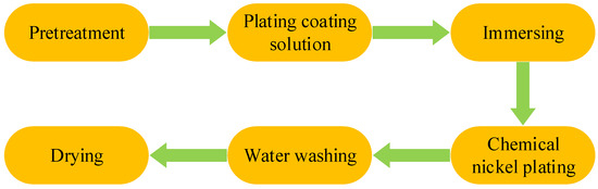
Figure 1.
Preparation process of nickel plating coating.
2.2. Drag Reduction Experiment with Nickel Plating Coating
An experimental setup is established to investigate the drag reduction effects of nickel coatings in hydraulic pipelines. The design measures the pressure difference across a horizontal circular pipeline to quantify drag reduction based on the principle that mechanical energy consists of kinetic and potential energy, with the latter encompassing both pressure and gravitational components. Since flow velocity and gravity are constants, only the pressure component is varied. Consequently, assessing pressure loss directly measures linear loss within the pipeline. Therefore, the linear loss can be evaluated by measuring the value of the pipeline pressure difference.
Figure 2 presents the design of an experimental setup for assessing drag reduction in hydraulic pipelines, featuring schematic 2a and physical 2b diagrams. The comprehensive system incorporates a power subsystem with a motor and pump, a control subsystem with valves to regulate force and flow, and an auxiliary subsystem consisting of an accumulator, filter, oil tank, temperature sensor, and stirrer for energy storage, fluid filtration, temperature control, and heat dissipation. Instruments such as pressure gauges, differential pressure sensors, and flow meters are deployed to quantify the pipeline’s operational parameters. A data acquisition unit is installed for real-time data collection, enabling continuous monitoring of pressure variations, oil tank temperature, and flow velocity throughout the experiment. The collective framework of power, control, and auxiliary subsystems is centralized around the fuel tank, linked by hoses to the test pipeline. This allows for direct pressure measurement and loss detection at both pipeline ends. The critical parameters that govern the experimental system are detailed in Table 1.
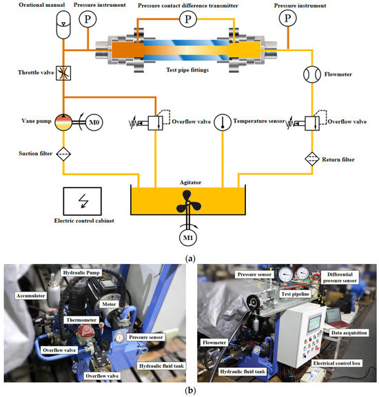
Figure 2.
Linear loss of a liquid pipeline. (a) Schematic diagram. (b) Physical diagram.

Table 1.
Test platform parameters.
This study investigates how various parameters affect the drag reduction in circular pipelines with laminar flow (Reynolds numbers Re < 2300). It utilizes seamless steel pipelines of uniform length but varying internal diameters for experimentation. The research evaluates the impact of different nickel coating thicknesses, pipeline diameters, and flow velocities on the linear losses within a hydraulic pipeline. By analyzing data across these variables, the study aims to discern their relative effects on drag reduction, thus contributing empirical data and theoretical insights to the field of fluid dynamics as it pertains to coating technologies for drag reduction.
The experimental setup includes pipelines of 1 m in length (l) with diameters (d) of 8 mm, 9 mm, and 10 mm, coatings of 10 µm, 20 µm, and 30 µm thicknesses (δ), and flow velocities (v) set at 5 m/s, 4 m/s, and 3 m/s, with an inlet pressure maintained at 5 MPa. Considering various factors, the selected inner diameter of the hydraulic steel pipeline is intended to sustain a laminar flow state. The pressures and flow rates employed in the experiments mirrored the standard operational parameters of the hydraulic system. A piping length of 1 m is sufficient for the oil to reach a fully developed flow upon entering and exiting the pipeline. When fluid is transported through pipelines, achieving a stable, predictable flow relies on sufficient pipeline length. This allows the fluid to reach a fully developed flow state by traveling within the pipeline, gradually conforming to its shape and dimensions, and stabilizing velocity, pressure, and distribution. Inadequate pipeline length can impede the fluid from fully adapting to the pipeline’s characteristics, leading to irregular flow patterns. This irregularity can heighten resistance during oil transportation, compromising flow efficiency and causing pressure fluctuations or uneven velocity distribution within the pipeline. Therefore, considering sufficient pipeline length in pipeline design is critical to ensuring consistent fluid flow. Optimal pipeline length contributes to improved fluid uniformity, reduced energy dissipation during fluid movement, and the maintenance of a stable flow regime throughout conveyance, ultimately enhancing the efficiency and reliability of the entire system. Choosing the correct pipe diameter and flow rate is crucial for enhancing hydraulic system performance and should align with the type of nickel selected in the electroplating process. Adjusting the pipeline diameter and flow rate effectively reduces losses. Coating addition aims to reduce drag by modifying surface smoothness and friction coefficient. The selected nickel coatings in the electroplating process complement each other for optimal performance. Coordination between the chosen coating, pipe diameter, and flow rate-matching liquid properties is essential for the most effective resistance reduction.
The study was meticulously designed to examine the drag-reducing potential of nickel coatings applied to hydraulic pipelines, specifically investigating the effects of varying coating thickness as the primary variable. Simultaneously, the research encompassed the assessment of pipeline diameters and flow velocities, recognized as crucial quantitative parameters under examination. The experimental framework was devised to deeply investigate how alterations in nickel coating thickness influence drag reduction within hydraulic pipelines. The study aimed to untangle the complex interrelationships among these variables by systematically manipulating coating thickness while considering diverse pipeline diameters and flow velocities. The overarching goal was to identify optimal conditions that minimize drag and enhance the overall efficiency of fluid flow in pipelines. This research aimed to provide comprehensive insights into the effectiveness of nickel coatings in reducing drag within hydraulic systems, with meticulous analysis and precise control of variables contributing to this fundamental understanding.
3. Experiment Results and Drag Reduction Mechanism
3.1. Experiment Results
The study rigorously examines how coating thickness, pipeline diameter, and flow velocity variations influence drag reduction. A robust experimental protocol is enacted to ensure result precision and consistency. The pipeline for this experiment selected three samples. Each sample underwent ten tests under various parameters, and each sample’s 10 sets of data were averaged. Subsequently, the average data of the three samples was calculated. Each set of experimental data falls within a reasonable error range. Upon reaching a steady temperature of 40 °C, pressure differentials are measured 10 times to average out fluctuations and secure stable outcomes. This repeated measurement approach negates anomalies, resulting in dependable and reproducible data. The aggregate findings in Table 2 reflect these methodically averaged results, underscoring the study’s commitment to experiment results.
Table 2.
Pressure difference.
This study used data from Table 2 to compare differential pressure values observed with and without coatings. Subsequently, it computed the drag reduction performance of nickel-plated coatings across varying coating thicknesses, pipeline diameters, and fluid flow rates, culminating in the presentation of findings in Table 3. This study achieved an unbiased evaluation of the nickel coating’s impact on fluid flow through a comprehensive comparison and analysis of differential pressure in coated versus uncoated scenarios. The calculation of drag reduction rates, indicative of the coating’s efficacy in mitigating pipeline resistance, was meticulously executed, considering diverse coating thicknesses, pipeline diameters, and fluid flow conditions. These systematically calculated values are meticulously arranged in Table 3, illustrating the influence of nickel-plated coatings on pipeline fluid flow across diverse scenarios.
Table 3.
Drag reduction rate.
Drag reduction rate η() is shown in Table 3 as follows:
This research evaluates how different factors like coating thickness, pipeline diameter, and flow velocity impact drag reduction in hydraulic systems. The study indicates that nickel coating leads to lower pressure differences and less linear loss than uncoated pipelines (Δpcoating < Δpcoating free). However, increasing the coating thickness does not always enhance drag reduction; it first lowers the pressure difference and then raises it (Δp20 > Δp30 > Δp10 > Δpcoating free), with the drag reduction rate peaking and then declining (η20 > η30 > η10). An optimal coating thickness (δ) of 20 µm achieves a maximum 5% drag reduction (η) at a 10 mm pipeline diameter (d) and 5 m/s flow velocity (v).
When the coating thickness and inlet flow velocity are constant but the pipeline diameter increases, there is a corresponding decrease in the pressure difference (Δp8 < Δp9 < Δp10) and an increase in the drag reduction rate (η8 < η9 < η10), underscoring the significant impact of pipeline diameter on pressure drop and drag reduction in hydraulic systems. Larger diameters appear to yield better drag reduction outcomes.
Similarly, with a constant coating thickness and pipeline diameter, an increase in inlet flow velocity results in a higher pressure difference (Δp3 < Δp4 < Δp5) and an ascending drag reduction rate (η3 < η4 < η5), showing that flow velocity also plays a critical role in the system’s pressure drop and can enhance drag reduction within certain limits.
These observations confirm that coating thickness, pipeline diameter, and inlet flow velocity significantly influence the pressure difference and drag reduction rate. They should be carefully balanced in the design and optimization of hydraulic systems. A disproportionate increase in coating thickness might introduce unnecessary costs and complexities without commensurate benefits in drag reduction, pointing to the importance of optimizing these parameters for practical applications.
3.2. Analysis of the Drag Reduction Mechanism
Frictional drag results from internal friction and is evaluated through simulations of internal fluid flow. The focus revolves around examining the characteristics of linear loss, necessitating the study of an incompressible, uniformly flowing fluid within a horizontally arranged, constant-diameter, straight pipeline. This pipeline maintains a consistent circular cross-sectional shape with an unchanging length and diameter. “Incompressible” signifies a constant fluid density, while “equidistant straight pipeline” indicates the pipeline’s sustained diameter. The term “constant flow” refers to the continual state of fluid flow within the channel. In Figure 3, sections 1 and 2 represent the inlet and outlet at z. The average flow velocity within the pipeline section progresses along the x-axis direction. Given the constant pipeline diameter, it is known from the continuity equation that v1 = v2.
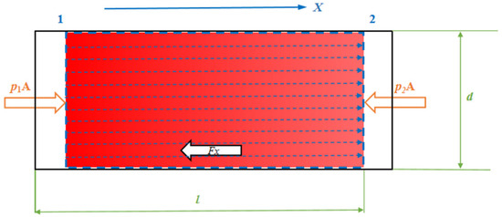
Figure 3.
Analysis of linear loss.
The total energy of the fluid (kinetic, pressure, and potential) will decrease as the fluid flows from Section 1 to Section 2, which is expressed according to Bernoulli’s equation listed as Equation (1) [29]:
where p1 and p2 are the pressures at the ends of the pipeline (Pa), ρ is the fluid density (kg/m3), v1 and v2 are the flow velocities at two points (m/s), g is the acceleration of gravity (m/s2), z1 and z2 are the positions of the two cross sections (m), and hf is the linear loss. If a circular pipeline placed horizontally has z1 = z2, ν1 = ν2, then the above formula is expressed as Equation (2):
where Δp is the linear loss, ρ is the fluid density, g is the acceleration of gravity, and hf is the linear loss.
The equation for linear loss for laminar flow in a circular tube is used to calculate the energy loss due to resistance during the along-travel flow of a fluid in a circular pipeline. Firstly, it is necessary to calculate the Reynolds number (Re), which is the ratio of the inertial and viscous forces of the fluid and represents the flow state of the fluid, calculated as Equation (3) [29]:
where ρ is the fluid density, v is the fluid velocity, d is the diameter of the circular tube, and μ is the fluid viscosity. The flow state of the fluid can be determined from the magnitude of Re < 2300, and the liquid is in a laminar flow state.
The linear loss can be calculated using the Darcy–Weisbach equation, which, when brought into Equation (2), can be derived as Equation (4):
where λ is the coefficient of head loss along the course; l is the length of the pipeline between the two pressure measurement points; d is the diameter of the pipeline; v is the average flow velocity of the section; g is the acceleration of gravity, taken as 9.81 m/s2.
The drag coefficient equation describes the relationship between the drag coefficient and the roughness of the inner pipeline wall in laminar flow. This coefficient, associated with fluid properties and the inner wall of the pipeline, measures the resistance created by the liquid’s motion within the channel. In scenarios with smooth wall conditions, where there’s minimal friction between the fluid and the wall, determining the resistance coefficient along the path during laminar flow is commonly feasible using the Darcy–Weisbach formula, as in Equation (6) [29]:
Bringing Equation (6) into Equation (5), the pressure loss for laminar flow in a circular pipeline can be obtained as Equation (7):
Based on the law of conservation of mass and the continuity equation, the equation for the average flow in a circular section can be derived as Equation (8) [29]:
where Q denotes flow rate, A denotes cross-sectional area, and v denotes flow velocity. For circular interfaces, d is the cross-sectional diameter.
Bringing Equation (8) into Poise Tuille’s law also gives the pressure loss for laminar flow in a circular tube as:
As per Equation (7), the differential pressure’s magnitude correlates with the flow velocity and the pipeline diameter. Specifically, the differential pressure shows a direct proportionality to the square of the flow velocity. When the pipeline diameter remains constant, higher flow rates amplify losses, resulting in increased pressure discrepancies. Conversely, the pressure demonstrates an inverse relationship with the pipeline diameter. Therefore, losses diminish with a consistent fluid flow rate as the pipeline diameter increases. The trends observed in Table 2 consistently validate and support Equation (7). Additionally, when maintaining a constant coating thickness and inlet flow rate, the differential pressure decreases as the pipeline diameter increases. Similarly, with a continuous coating thickness and pipeline diameter, the differential pressure rises as the flow rate increases.
Accessing the information, the absolute roughness of the inner surface of the new seamless steel pipeline is approximately between 0.01 and 0.02 mm, where the surface particles, averaging about 20 µm high, are modeled as uniform arc-shaped protrusions (Figure 4). This model enables a more precise evaluation of how the coating fills and covers the pipeline’s roughness, determining the ideal thickness for practical and durable coverage. The findings suggest that the roughness level is critical to determining the necessary coating thickness, which must be ample to envelop the pipeline’s uneven texture, ensuring the coating’s performance and longevity. The roughness of the coated pipeline changes. With coating thicknesses of 10 µm and 20 µm, the roughness decreases. However, at a coating thickness of 30 µm, the coating covers the surface roughness, resulting in a smooth pipeline.
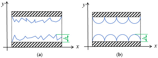
Figure 4.
Cross-sectional view of the pipeline interior. (a) True texture of the internal wall. (b) Simplified representation of the internal wall.
Figure 5 depicts the axial cross-section of a pipeline, where the flow within is characterized as laminar. Given the no-slip condition at the wall, the adjacent oil layer remains still, with the flow velocity of subsequent layers increasing progressively away from the wall in the standard (y) direction. This creates a boundary layer extending across the entire pipeline, which can induce turbulence near the border.
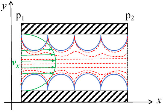
Figure 5.
The internal flow of the pipeline.
Figure 6 illustrates a fluid section of length Δx inside a pipeline with radius R, where the flow is steady and laminar. The inlet pressure is p1, and the friction coefficient between the pipeline and the pipeline wall is μ. The pressure gradient is consistent along the flow’s direction, leading to an outlet pressure represented by Equation (10). This gives rise to a pressure difference across the pipeline length, as shown in Equation (11). The shear force F at the wall arises due to the friction between the fluid and the pipeline, which is Equation (12).
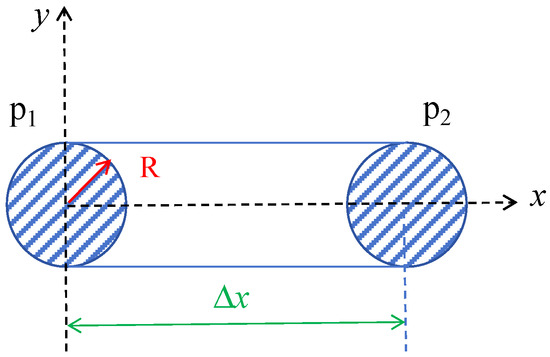
Figure 6.
Shear stress.
Given the laminar flow without velocity changes, the net force equals 0, simplifying Equations (13) and (14). The velocity of the oil near any surface irregularities is divided into components along the flow vx and perpendicular to vy (Figure 6). The more significant the velocity gradient in the x direction of flow (dvx0/dt > dvx10/dt > dvx20/dt) corresponds to a higher friction coefficient, a thinner boundary layer, and more significant shear stress between adjacent flow layers. An increase in vy, the velocity component perpendicular to the flow, enhances momentum exchange between layers, equalizing the velocities and reducing shear stress.
The velocity of the oil near any surface irregularities is divided into components along the flow vx and perpendicular to vy (Figure 7). The more significant the velocity gradient in the x direction of flow (dvx0/dt > dvx10/dt > dvx20/dt) corresponds to a higher friction coefficient, a thinner boundary layer, and more significant shear stress between adjacent flow layers. An increase in vy, the velocity component perpendicular to the flow, enhances momentum exchange between layers, equalizing the velocities and reducing shear stress. In Figure 7, the red arrows depict momentum interactions, whereas the yellow dots represent intermolecular thermal motion.
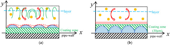
Figure 7.
Inter-layer momentum transfer in fluid flow. (a) Molecular thermal motion across Laminar sheets. (b) Combined thermal motion and fluid y direction dynamics in flow layers.
In Figure 8, the distance Sx from the bottom to the top of any surface irregularities diminishes, resulting in a reduced pressure difference (p1 > p2 > p3) along the flow direction. With a thicker coating, the flow’s velocity gradient next to these protrusions decreases in the x direction, while momentum exchange continues in the y direction. These two effects lead to a drop in shear stress and flow resistance over the protrusions. The optimal drag reduction is observed with a 20 µm coating, where the pipeline surface becomes smoother, reducing turbulence. At 30 µm, despite a further smoothed surface, the velocity vy effectively reaches 0, causing momentum exchange to diminish and rely solely on molecular motion, which decreases the drag reduction effect. Nonetheless, this effect remains superior to that observed with thinner coatings of 10 µm and uncoated pipelines.
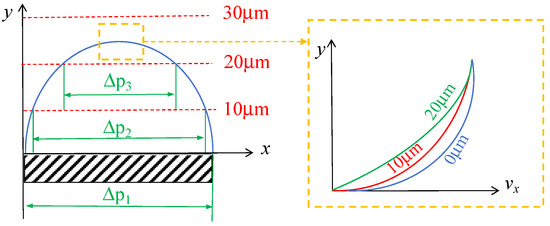
Figure 8.
Velocity gradient adjacent to surface protrusions.
Furthermore, the internal pressure and the pressure gradient escalate when the pipeline’s diameter expands or its flow rate quickens under unchanged conditions. This increase results in a more significant pressure difference (dΔp/dx) around protrusions. The pressure variation around these particles increases as the pressure gradient increases. Under these conditions, the drag reduction becomes more marked as the coating proves more effective in reducing fluid flow resistance at elevated pressure gradients.
4. Conclusions
This study provides an in-depth examination of nickel plating coatings’ efficacy in minimizing linear losses within hydraulic pipelines, focusing on the effects of coating thickness, pipeline diameter, and flow velocity on drag reduction. The research indicates that employing nickel-coated pipelines can effectively lower pressure differentials compared to uncoated ones. This decrease in pressure difference directly correlates with reduced linear losses within the system. The primary cause of the decrease in pressure difference is the reduction in overall loss along the pipeline. Formula (2) in Section 3 elucidates the relationship between these two factors. Nickel plating demonstrates the capability to diminish losses along hydraulic lines and optimize fluid flow. An optimal coating thickness of 20 µm achieves a maximum 5% drag reduction at a 10 mm pipeline diameter and 5 m/s flow velocity. The optimal drag reduction is observed with a 20 µm coating; at 30 µm, this effect remains superior to that observed with thinner coatings of 10 µm and uncoated pipelines. The diameter of the line and the inlet flow rate impact the losses incurred during line travel. Enlarging the line diameter or augmenting the flow rate will alleviate losses along the hydraulic line. Simultaneously, the study shows that both pipeline diameter and flow velocity significantly affect drag reduction, with increases in either leading to improved rates. This emphasizes the importance of careful diameter and velocity selections to enhance hydraulic system performance.
These insights are pivotal for refining drag reduction strategies in hydraulic systems and recommending tailored adjustments of coating parameters to suit specific operational requirements. The conclusions drawn here serve as a resource for engineering design, contributing to the enhanced efficiency of hydraulic pipelines. The research results of this paper provide a reliable reference for using coatings to reduce hydraulic pipeline losses, which is highly beneficial for drag reduction technology research. However, the method used to minimize losses in hydraulic hoses has limitations. In this study, the coating underwent chemical nickel plating as part of the processing methodology. The limitations of the processing technology constrained the coating thickness, and there was no exploration or comparison of thickness variations across other dimensions. Future research endeavors could explore more rational processing techniques, such as composite metal coatings, to increase coating thickness and enhance drag reduction capabilities.
Author Contributions
Conceptualization, X.W.; data curation, B.Y. and W.L.; methodology, X.W.; writing—review and editing, J.Z. All authors have read and agreed to the published version of the manuscript.
Funding
This research was funded by the Scientific research projects of ministries and commissions (Grant No. 3030021322304).
Data Availability Statement
The data presented in this study are available on request from the corresponding author.
Conflicts of Interest
The authors declare no conflicts of interest.
Correction Statement
This article has been republished with a minor correction to the existing affiliation information. This change does not affect the scientific content of the article.
References
- Burger, E.D.; Chorn, L.G.; Perkins, T.K. Perkins. Studies of drag reduction conducted over a broad range of pipeline conditions when flowing prudhoe bay crude oil. J. Rheol. 1980, 24, 603–626. [Google Scholar] [CrossRef]
- Golda, J. Hydraulic transport of coal in pipes with drag reducing additives. Chemical Eng. Commun. 1986, 43, 53–67. [Google Scholar] [CrossRef]
- Yunqing, G.; Junjun, Z.; Songwei, Y.; Chengqi, M.; Zhou, L.; Chendong, H.; Denghao, W.; Jiegang, M.; Yun, R. Unsteady numerical simulation method of hydrofoil surface cavitation. Int. J. Mech. Sci. 2022, 228, 107490. [Google Scholar]
- Vakarelski, I.U.; Kamoliddinov, F.; Jetly, A.; Thoroddsen, S.T. When superhydrophobicity can be a drag: Ventilated cavitation and splashing effects in hydrofoil and speed-boat models tests. Colloids Surf. A Physicochem. Eng. 2021, 628, 127344. [Google Scholar] [CrossRef]
- Hnativ, R.; Verbovskiy, O. Distribution of local velocities in a circular pipe with accelerating fluid flow. East. Eur. J. Enterp. Technol. 2019, 2, 58–63. [Google Scholar] [CrossRef]
- Li, Y.Z.; Woo, Y.; Manoj, S.; Srikanth, N.; Dong, Z.L. Effect of nano-titanium dioxide contained in titania-polyurea coating on marina biofouling and drag reduction. J. Biomed. Nanotechnol. 2021, 16, 1530–1541. [Google Scholar] [CrossRef] [PubMed]
- Cho, Y.; Jeon, K.H.; Lee, S.B.; Park, H.; Lee, I. Evaluation of in-service speed performance improvement by means of FDR-AF (frictional drag reducing anti-fouling) marine coating based on ISO19030 standard. Sci. Rep. 2021, 11, 1062. [Google Scholar] [CrossRef] [PubMed]
- Saadatbakhsh, M.; Asl, S.J.; Kiani, M.J.; Nouri, N.M. Slip length measurement of pdms/hydrophobic silica superhydrophobic coating for drag reduction application. Surf. Coat. Technol. 2020, 404, 126428. [Google Scholar] [CrossRef]
- Rose, J.B. Interfacial slip-and-drag reduction by superhydrophobic polymer coating. In Superhydrophobic Polymer Coatings; Elsevier: Amsterdam, The Netherlands, 2019; pp. 299–319. [Google Scholar]
- Yunqing, G.; Longbiao, M.; Muhan, Y.; Chendong, H.; Junjun, Z.; Jiegang, M.; Denghao, W.; Yun, R. Strategies for improving friction behavior based on carbon nanotube additive materials. Tribol. Int. 2022, 176, 107875. [Google Scholar]
- Bellemare, J.; Laliberté-Riverin, S.; Ménard, D.; Brochu, M.; Sirois, F. Coating density as the key factor behind hydrogen embrittlement of cadmium-plated 4340 steel. J. Appl. Electrochem. 2020, 50, 1045–1058. [Google Scholar] [CrossRef]
- Mawignon, F.J.; Qin, L.; Kouediatouka, A.N.; Lu, S.; Yang, H.; YEO, K.F.H.; Dong, G. Highly strong bio-inspired ZnO/PDMS superhydrophobic surface with drag reduction and antibacterial properties. Tribol. Int. 2023, 189, 109003. [Google Scholar] [CrossRef]
- Hansen, R.J.; Hunston, D.L. An experimental study of turbulent flows over compliant surfaces. J. Sound Vib. 1974, 34, 297–308. [Google Scholar] [CrossRef]
- Li, L.C.; Liu, B.; Hao, H.L.; Li, L.Y.; Zeng, Z.X. Investigation of the drag reduction performance of bionic flexible coating. Phys. Fluids 2020, 32, 084103. [Google Scholar] [CrossRef]
- Lv, X.S.; Qin, Y.; Liang, H.; Zhao, B.; Cui, X. A facile method for constructing a superhydrophobic zinc coating on a steel surface with anti-corrosion and drag-reduction properties. Appl. Surf. Sci. 2021, 562, 150192. [Google Scholar] [CrossRef]
- Rowin, W.A.; Asha, A.B.; Narain, R.; Ghaemi, S. A novel approach for drag reduction using polymer coating. Ocean Eng. 2021, 240, 109895. [Google Scholar] [CrossRef]
- Ott, J.O.; Lazalde, M.T.; Gu, G.X. Algorithmic-driven design of shark denticle bioinspired structures for superior aerodynamic properties. Bioinspiration Biomim. 2020, 15, 026001. [Google Scholar] [CrossRef] [PubMed]
- Gu, Y.; Yu, S.; Mou, J. Research progress on the collaborative drag reduction effect of polymers and surfactants. Materials 2020, 13, 444. [Google Scholar] [CrossRef]
- Wang, Y.H.; Zhang, Z.B.; Xu, J.K. One-step method using laser for large-scale preparation of bionic superhydrophobic & drag-reducing fish-scale surface—ScienceDirect. Surf. Coat. Technol. 2021, 409, 126801. [Google Scholar]
- Zhu, Y.; Yang, F.C.; Guo, Z.G. Bioinspired surfaces with special micro-structures and wettability for drag reduction: Which surface design will be a better choice? Nanoscale 2021, 13, 6. [Google Scholar] [CrossRef]
- Bonin, B.V.; Delaunois, F. Replacement of Lead stabilizer in electroless Nickel-Boron baths: Synthesis and characterization of coatings from bismuth stabilized bath. Sustain. Mater. Technol. 2020, 23, e00130. [Google Scholar] [CrossRef]
- Azli, N.N.; Amin, N.F.; Oluhende, S.T.; Mohamad, S.Z.; Fadil, N.A. Electroless deposited black nickel-phosphorous solar absorber coatings on carbon steel: Effect of plating bath pH. Mater. Today Proc. 2020, 39, 1071–1076. [Google Scholar] [CrossRef]
- Wu, W.; Huang, J.; Nther, J.; Omar, N.A.; Kster, F. Texture orientation, morphology and performance of nanocrystalline nickel coatings electrodeposited from a Watts-type bath: Effects of H3BO3 concentration and plating time. Surf. Coat. Technol. 2021, 424, 127648. [Google Scholar] [CrossRef]
- Yue, B.W.; Zhu, G.M.; Wang, Y.W.; Song, J.B.; Chang, Z. Uncertainty analysis of factors affecting coating thickness distribution during nickel electrodeposition. J. Electroanal. Chem. 2021, 891, 115274. [Google Scholar] [CrossRef]
- Güler, O.; Varol, T.; Alver, Ü.; Biyik, S. The wear and arc erosion behavior of novel copper based functionally graded electrical contact materials fabricated by hot pressing assisted electroless plating. Adv. Powder Technol. 2021, 32, 2873–2890. [Google Scholar] [CrossRef]
- Chen, M.; Dong, W.; Qin, C. A Method for Electroless Nickel Plating on Aluminum Alloy Surface. Eng. Sci. 2020, 5, 33. [Google Scholar] [CrossRef]
- Salicio-Paz, A.; Grande, F.; Pellicer, E.; Sort, J.; Fornell, J. Monolayered versus multilayered electroless NiP coatings: Impact of the plating approach on the microstructure, mechanical and corrosion properties of the coatings. Surf. Coat. Technol. 2019, 368, 138–146. [Google Scholar] [CrossRef]
- Fu, H.; Lu, Y.; Liang, H.R.; Wang, S.; Ling, K.G. Diagnosis of the single leakage in the fluid pipeline through experimental study and CFD simulation. J. Pet. Sci. Eng. 2020, 193, 107437. [Google Scholar] [CrossRef]
- White, F. Fluid Mechanics; McGraw-Hill Education: New York, NY, USA, 2010. [Google Scholar]
Disclaimer/Publisher’s Note: The statements, opinions and data contained in all publications are solely those of the individual author(s) and contributor(s) and not of MDPI and/or the editor(s). MDPI and/or the editor(s) disclaim responsibility for any injury to people or property resulting from any ideas, methods, instructions or products referred to in the content. |
© 2024 by the authors. Licensee MDPI, Basel, Switzerland. This article is an open access article distributed under the terms and conditions of the Creative Commons Attribution (CC BY) license (https://creativecommons.org/licenses/by/4.0/).