Analysis of Thermo-Hydrodynamic Lubrication of Three-Lobe Semi-Floating Ring Bearing Considering Temperature–Viscosity Effect and Static Pressure Flow


Abstract
:1. Introduction
2. Theoretical
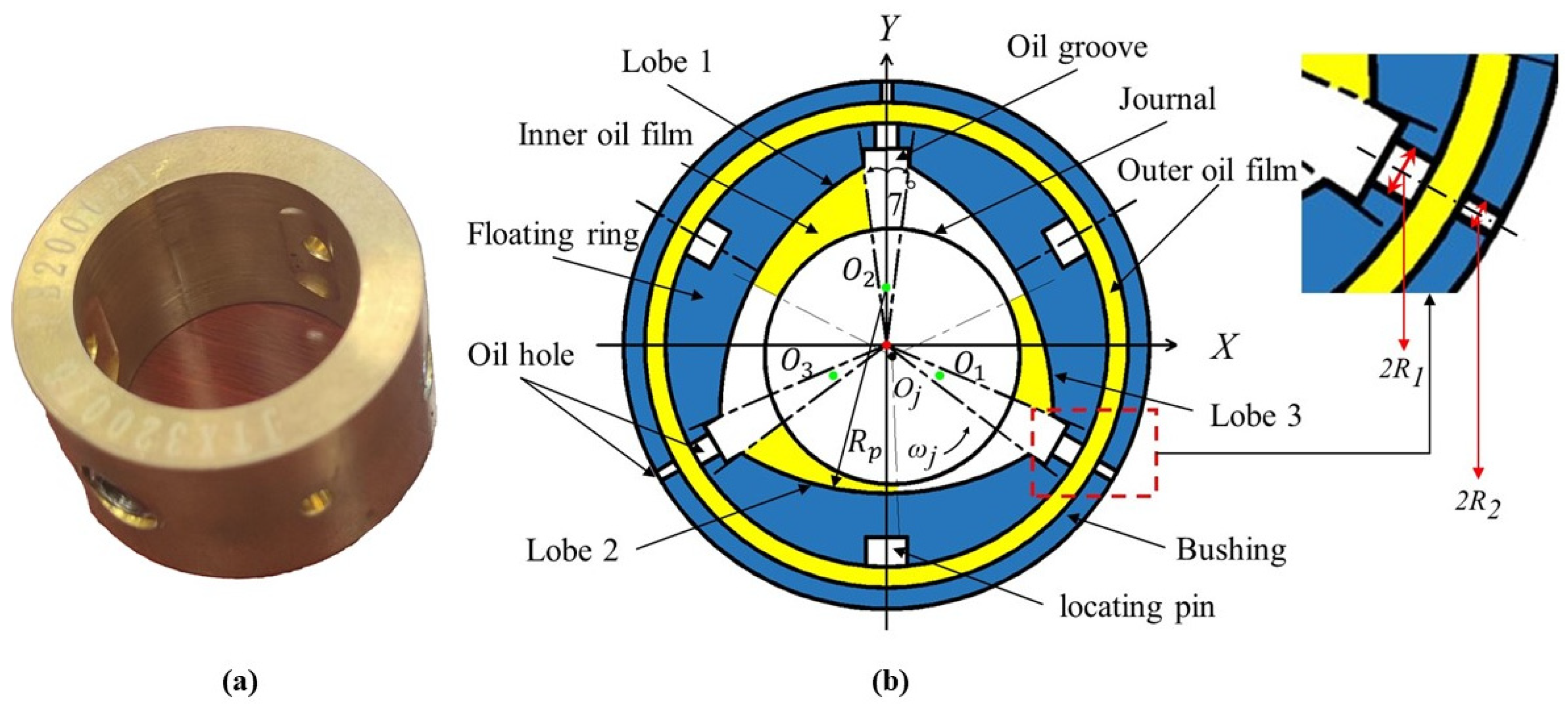
2.1. Physical Model
2.2. Mathematical Model
2.2.1. Dynamic Pressure Equation
2.2.2. Thickness Equation
2.2.3. Thermal Equation
2.2.4. Static Characteristic Parameters
2.2.5. Dynamic Coefficients
2.2.6. Boundary Conditions
3. Procedure and Verification
3.1. The Solution Procedure
3.2. Verification of Pressure and Static Characteristics Parameters
4. Results and Discussion
4.1. Effect of Operating Parameters on the Static Characteristics
4.1.1. Effect of Operating Parameters on the Temperature Rise
4.1.2. Effect of Operating Parameters on the Power Loss
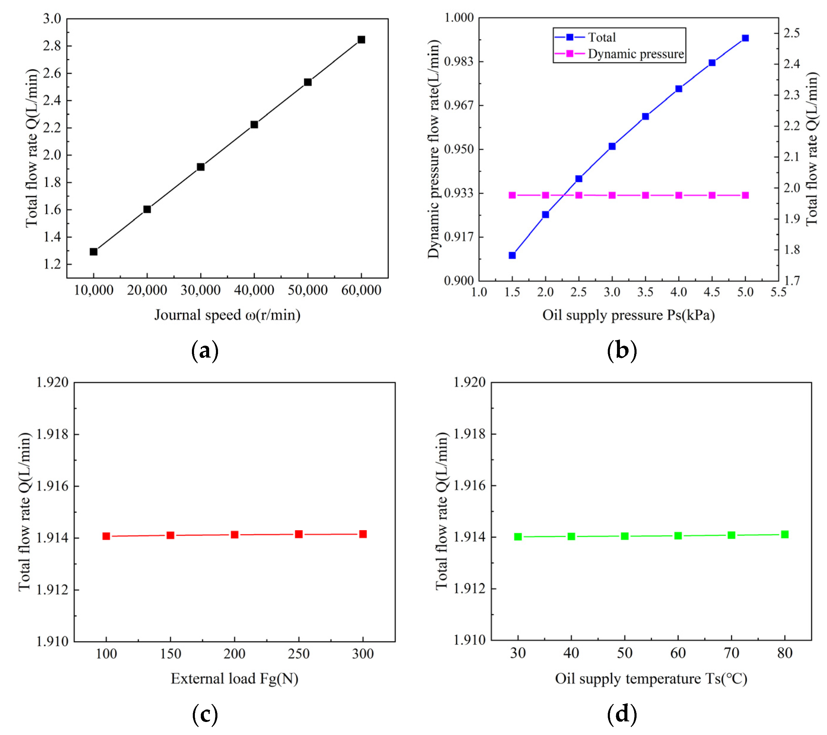
4.1.3. Effect of Operating Parameters on the End Leakage
4.1.4. Effect of Operating Parameters on Eccentricity Ratio and Attitude Angle
4.1.5. Effect of Operating Parameters on the Maximum Film Pressure
4.1.6. Effect of Operating Parameters on the Minimum Film Thickness
4.2. Effect of Operating Parameters on the Dynamic Characteristics
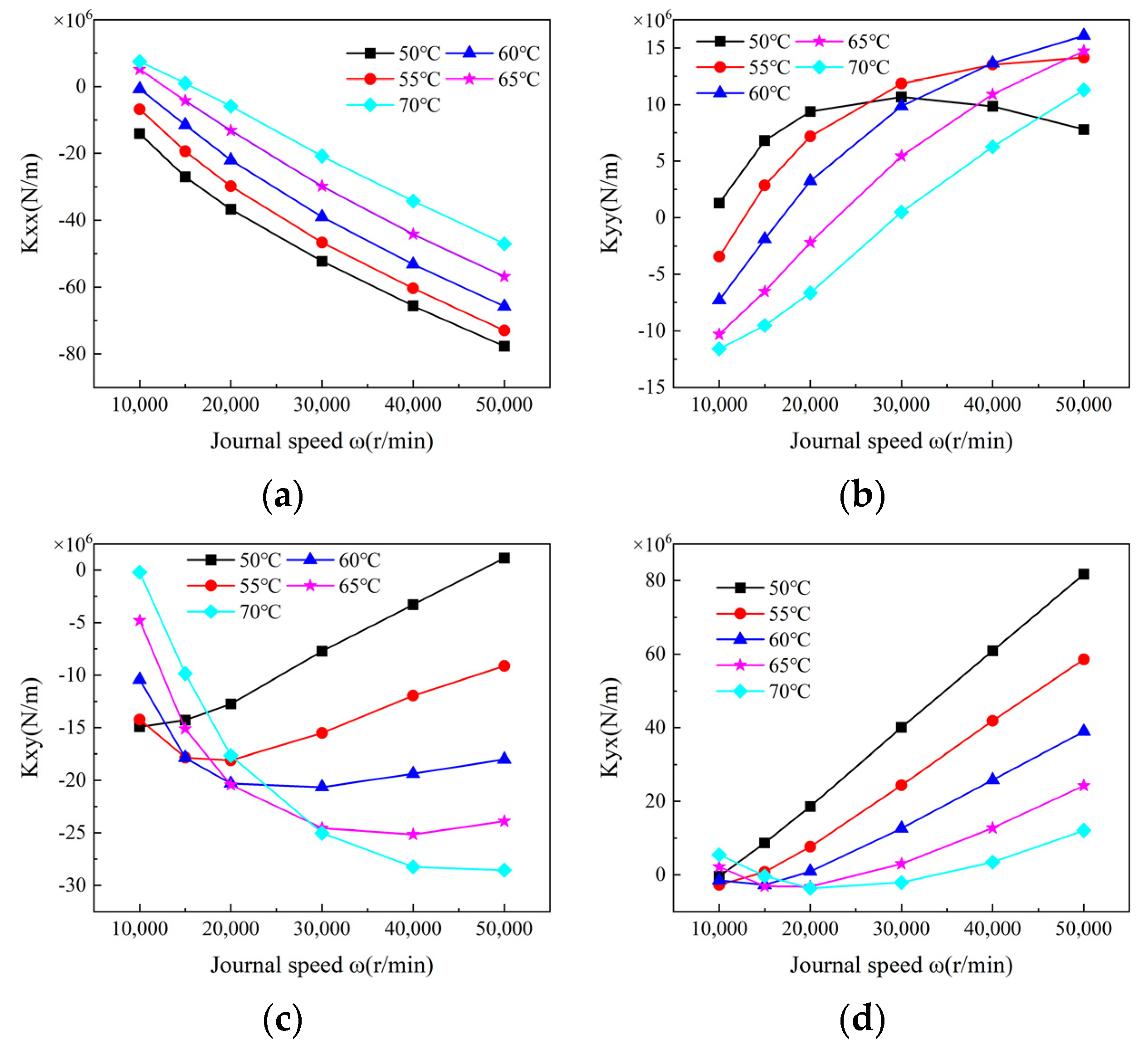
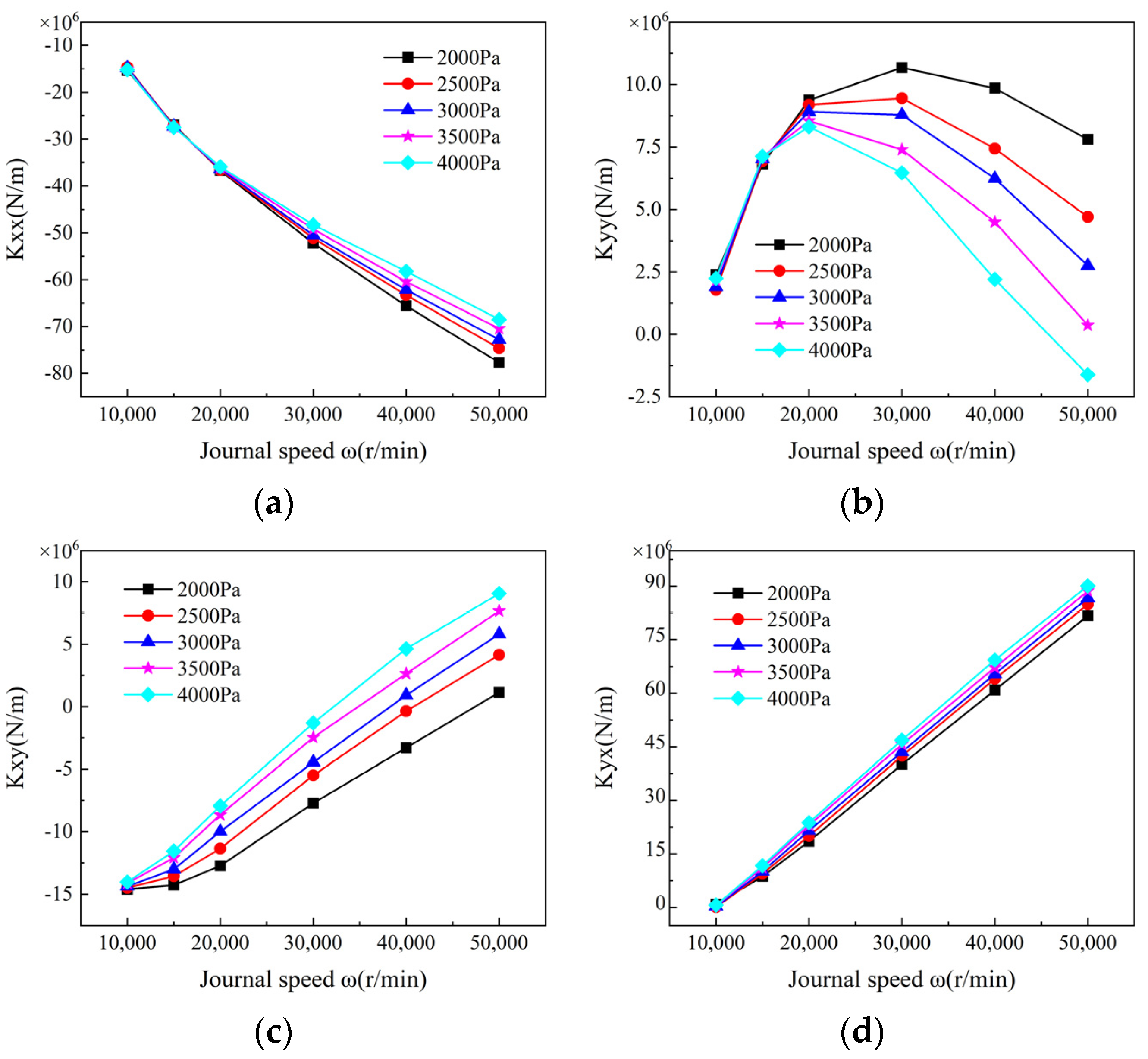
4.2.1. Coupling Effect on the Stiffness Coefficients
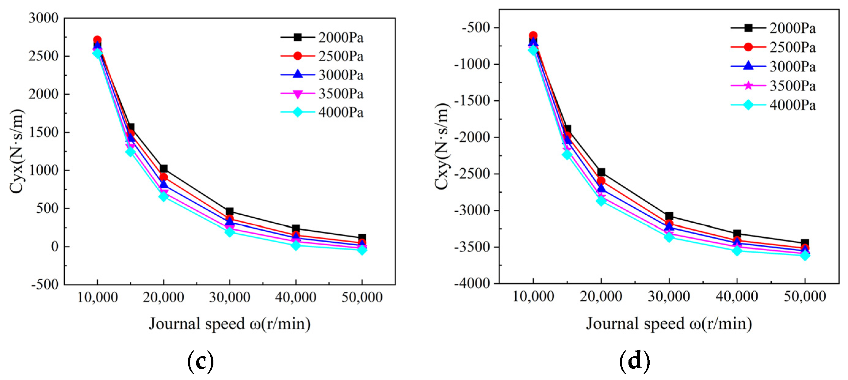
4.2.2. Coupling Effect on the Damping Coefficients
5. Conclusions
Author Contributions
Funding
Data Availability Statement
Conflicts of Interest
Nomenclature
| , , | Heat transfer area of inner oil film, floating ring, outer oil film |
| , | Area of inner film flank, outer film flank |
| Radius clearance of lobe | |
| Cb | Radius clearance of bearing |
| cp | Heat transfer coefficient |
| , , , | Damping coefficients under coordinates |
| , , , | Damping coefficients under coordinates |
| e | Eccentricity of journal |
| F, Fg | Oil film load capacity, external load |
| h, | Oil film thickness, minimum film thickness |
| , | Pressure loss of inner film, outer film |
| , , , | Stiffness coefficients under coordinates |
| , , , | Stiffness coefficients under X–Y coordinates |
| m | Preload factor |
| N1, N2 | Number of holes on floating ring, on bushing |
| P, | Pressure, maximum pressure |
| , , , | Disturbance pressure |
| Power loss based on dynamic pressure equation | |
| , , | Pressure of inlet on floating ring, on bushing, supply pressure |
| Q, , ,, | Flow rate, flow rate of inner film, outer film, dynamic pressure flow rate of inner film, static pressure flow rate of inner film |
| Rj, R1, R2 | Journal radius, radius of hole on floating ring, on bushing |
| Ts, , , | Supply oil temperature, temperature rise of inner film, outer film, ring |
| Journal linear velocity | |
| α | Lobe sequence number, α = 1, 2, 3 |
| Cover angle of lobe | |
| Journal eccentricity ratio | |
| Attitude angle | |
| κ | Oil specific heat |
| Pressure loss coefficient | |
| μ | Oil viscosity |
| ρ | Oil density |
| Journal rotation speed |
Appendix A

References
- Kirk, R.G. Experimental Evaluation of Hydrodynamic Bearings for a High Speed Turbocharger. J. Eng. Gas Turbines Power 2014, 136, 072501. [Google Scholar] [CrossRef]
- Zhang, Y.; Wang, W.; Wei, D.G.; Wang, G.; Xu, J.M.; Liu, K. Coupling analysis of tribological and dynamical behavior for a thermal turbulent fluid lubricated floating ring bearing-rotor system at ultra-high speeds. Tribol. Int. 2022, 165, 107325. [Google Scholar] [CrossRef]
- Tian, L.; Wang, W.J.; Peng, Z.J. Nonlinear effects of unbalance in the rotor-floating ring bearing system of turbochargers. Mech. Syst. Signal Process. 2013, 34, 298–320. [Google Scholar] [CrossRef]
- Eling, R.; Te Wierik, M.; Van Ostayen, R.; Rixen, D. Rotordynamic and Friction Loss Measurements on a High Speed Laval Rotor Supported by Floating Ring Bearings. Lubricants 2017, 5, 7. [Google Scholar] [CrossRef]
- Cao, J.; Dousti, S.; Allaire, P.; Dimond, T. Nonlinear Transient Modeling and Design of Turbocharger Rotor/Semi-Floating Bush Bearing System. Lubricants 2017, 5, 16. [Google Scholar] [CrossRef]
- Zhang, Y.; Wang, W.; Wei, D.; Wang, G.; Xu, J.; Liu, K. Dynamic stability of unbalance-induced vibration in a turbocharger rotor-bearing system with the nonlinear effect of thermal turbulent lubricating fluid film. J. Sound Vib. 2022, 528, 116909. [Google Scholar] [CrossRef]
- Chen, W.J. Rotordynamics and bearing design of turbochargers. Mech. Syst. Signal Process. 2012, 29, 77–89. [Google Scholar] [CrossRef]
- Schweizer, B. Dynamics and stability of turbocharger rotors. Arch. Appl. Mech. 2009, 80, 1017–1043. [Google Scholar] [CrossRef]
- Orcutt, F.K.; Ng, C.W. Steady-State and Dynamic Properties of the Floating-Ring Journal Bearing. J. Lubr. Technol. 1968, 90, 243–253. [Google Scholar] [CrossRef]
- Nikolajsen, J.L. The Effect of Variable Viscosity on the Stability of Plain Journal Bearings and Floating-Ring Journal Bearings. J. Lubr. Technol. 1973, 95, 447–456. [Google Scholar] [CrossRef]
- Mokhtar, M.O.A. Floating ring journal bearings: Theory, design and optimization. Tribol. Int. 1981, 14, 113–119. [Google Scholar] [CrossRef]
- Li, C.-H.; Rohde, S.M. On The Steady State and Dynamic Performance Characteristics of Floating Ring Bearings. J. Lubr. Technol. 1981, 103, 389–397. [Google Scholar] [CrossRef]
- Clarke, D.M.; Fall, C.; Hayden, G.N.; Wilkinson, T.S. A Steady-State Model of a Floating Ring Bearing, Including Thermal Effects. J. Tribol. 1992, 114, 141–149. [Google Scholar] [CrossRef]
- Jung, W.; San Andres, L.; Kim, J. A Nonlinear Rotordynamics Model for Automotive Turbochargers Coupled to a Physical Model for A (Semi) Floating Ring Bearing System. J. Eng. Gas Turbines Power 2022, 144, 111002. [Google Scholar] [CrossRef]
- San Andrés, L.; Jung, W.; Hong, S.-K. A Thermo-Hydrodynamic Model for Thermal Energy Flow Management in A (Semi) Floating Ring Bearing System for Automotive Turbochargers. J. Eng. Gas Turbines Power 2021, 143, 011013. [Google Scholar] [CrossRef]
- San Andrés, L.; Yu, F.; Gjika, K. On the Influence of Lubricant Supply Conditions and Bearing Configuration to the Performance of (Semi) Floating Ring Bearing Systems for Turbochargers. J. Eng. Gas Turbines Power 2017, 140, 032503. [Google Scholar] [CrossRef]
- Gjika, K.; San Andrés, L.; Larue, G.D. Nonlinear Dynamic Behavior of Turbocharger Rotor-Bearing Systems with Hydrodynamic Oil Film and Squeeze Film Damper in Series: Prediction and Experiment. J. Comput. Nonlin. Dyn. 2010, 5, 041006. [Google Scholar] [CrossRef]
- Andres, L.S.; Rivadeneira, J.C.; Gjika, K.; Groves, C.; LaRue, G. Rotordynamics of small turbochargers supported on floating ring bearings—Highlights in bearing analysis and experimental validation. J. Tribol. T Asme 2007, 129, 391–397. [Google Scholar] [CrossRef]
- Andrés, L.S.; Rivadeneira, J.C.; Gjika, K.; Groves, C.; LaRue, G. A Virtual Tool for Prediction of Turbocharger Nonlinear Dynamic Response: Validation Against Test Data. J. Eng. Gas Turbines Power 2006, 129, 1035–1046. [Google Scholar] [CrossRef]
- Duan, W.; Chu, F.; Kim, C.-H.; Lee, Y.-B. A bulk-flow analysis of static and dynamic characteristics of floating ring seals. Tribol. Int. 2007, 40, 470–478. [Google Scholar] [CrossRef]
- Pei, S.; Xu, H.; Yun, M.; Shi, F.; Hong, J. Effects of surface texture on the lubrication performance of the floating ring bearing. Tribol. Int. 2016, 102, 143–153. [Google Scholar] [CrossRef]
- Wang, X.; Li, H.; Lu, W.; Meng, G. Stiffness and Damping Properties of (Semi) Floating Ring Bearing Using Magnetorheological Fluids as Lubricant. J. Tribol. 2017, 139, 051701. [Google Scholar] [CrossRef]
- Guo, H.; Yang, S.; Zhang, S.; Zhang, Z. Influence of temperature–viscosity effect on ring-journal speed ratio and stability for a hydrodynamic floating ring bearing. Ind. Lubr. Tribol. 2019, 71, 540–547. [Google Scholar] [CrossRef]
- Zhang, C.; Men, R.; Wang, Y.; He, H.; Chen, W. Experimental and numerical investigation on thermodynamic performance of full-floating ring bearings with circumferential oil groove. Proc. Inst. Mech. Eng. Part J J. Eng. Tribol. 2019, 233, 1182–1196. [Google Scholar] [CrossRef]
- Dyk, Š.; Smolík, L.; Rendl, J. Predictive capability of various linearization approaches for floating-ring bearings in nonlinear dynamics of turbochargers. Mech. Mach. Theory 2020, 149, 103843. [Google Scholar] [CrossRef]
- Yang, S.; Guo, H.; Zhang, S.-L.; Xia, B.-Q. Thermohydrodynamic Characteristics and Stability Analysis for a Journal Hybrid Floating Ring Bearing within Laminar and Turbulent Mixed Flow Regime. J. Tribol. 2020, 143, 031801. [Google Scholar] [CrossRef]
- Ziese, C.; Irmscher, C.; Nitzschke, S.; Daniel, C.; Woschke, E.; Klimpel, T. Influence of Lubricant Film Cavitation on the Vibration Behavior of a Semifloating Ring Supported Turbocharger Rotor with Thrust Bearing. J. Eng. Gas Turbines Power 2022, 144, 041014. [Google Scholar] [CrossRef]
- Xie, Z.; Zhu, W. An investigation on the lubrication characteristics of floating ring bearing with consideration of multi-coupling factors. Mech. Syst. Signal Process. 2022, 162, 108086. [Google Scholar] [CrossRef]
- Soni, S.; Vakharia, D. Dynamic performance analysis of a noncircular cylindrical floating ring bearing. Proc. Inst. Mech. Eng. Part J J. Eng. Tribol. 2017, 231, 745–765. [Google Scholar] [CrossRef]
- Soni, S.; Vakharia, D. A steady-state performance analysis of a non-circular cylindrical floating ring journal bearing. Proc. Inst. Mech. Eng. Part J J. Eng. Tribol. 2017, 231, 41–56. [Google Scholar] [CrossRef]
- Zhang, C.; Wang, Y.; Men, R.; He, H.; Chen, W. The effect of three-lobed bearing shapes in floating-ring bearings on the nonlinear oscillations of high-speed rotors. Proc. Inst. Mech. Eng. Part J J. Eng. Tribol. 2020, 234, 751–769. [Google Scholar] [CrossRef]
- Zhang, C.; Wang, Y.; Men, R.; He, H.; Chen, W. Dynamic behaviors of a high-speed turbocharger rotor on elliptical floating-ring bearings. Proc. Inst. Mech. Eng. Part J J. Eng. Tribol. 2019, 233, 1785–1799. [Google Scholar] [CrossRef]
- San Andrés, L.; Kerth, J. Thermal effects on the performance of floating ring bearings for turbochargers. Proc. Inst. Mech. Eng. Part J J. Eng. Tribol. 2004, 218, 437–450. [Google Scholar] [CrossRef]
- User Manuals of Fluent. Available online: https://ansyshelp.ansys.com/account/secured?returnurl=/Views/Secured/prod_page.html?pn=Fluent&pid=Fluent&lang=en (accessed on 3 April 2024).
- User Manuals and Documentation of Dyrobes. Available online: https://dyrobes.com/features/user-manuals/ (accessed on 3 April 2024).


| Parameters | Value | Parameters | Value |
|---|---|---|---|
| Rotor speed | 64,500 r/min | External load Fg | 63.49 N |
| Oil supply pressure Ps | 0.2 MPa | Preload factor m | 0.8592 |
| Bearing length L | 20.2 mm | Oil-specific heat κ | 2000 J/kg·°C |
| Radius clearance Cp | 0.149148 mm | Oil density ρ | 850 kg/ |
| Radius clearance Cb | 0.021 mm | Heat transfer coefficient cp | 0.13 W/m·K |
| Rotor radius Rj | 12.35 mm | Oil supply temperature Ts | 50 °C |
| Radius of hole R1 | 3 mm | Number of holes N1 | 3 |
| Radius of hole R2 | 1.6 mm | Number of holes N2 | 3 |
| Surface roughness σ | 0.8 μm |
| Performance Parameters | Dyrobes | Present | Relative Error |
|---|---|---|---|
| Maximum pressure /Mpa | 7.8268 | 7.1973 | 8.0% |
| Minimum film thickness /mm | 0.02045 | 0.02039 | 0.29% |
| Attitude angle /deg | 23.8 | 22.1 | 7.1% |
| Power loss /kW | 3.12451 | 2.98549 | 4.4% |
| Flow rate Q/lpm | 1.832 | 2.005 | 9.44% |
| Eccentricity ratio e/Cb | 0.0287 | 0.0310 | 8.0% |
| Viscosity μ/cPoise | 10.6601 | 9.8037 | 8.0% |
Disclaimer/Publisher’s Note: The statements, opinions and data contained in all publications are solely those of the individual author(s) and contributor(s) and not of MDPI and/or the editor(s). MDPI and/or the editor(s) disclaim responsibility for any injury to people or property resulting from any ideas, methods, instructions or products referred to in the content. |
© 2024 by the authors. Licensee MDPI, Basel, Switzerland. This article is an open access article distributed under the terms and conditions of the Creative Commons Attribution (CC BY) license (https://creativecommons.org/licenses/by/4.0/).
Share and Cite
Dong, J.; Wen, H.; Zhu, J.; Guo, J.; Zong, C. Analysis of Thermo-Hydrodynamic Lubrication of Three-Lobe Semi-Floating Ring Bearing Considering Temperature–Viscosity Effect and Static Pressure Flow. Lubricants 2024, 12, 140. https://doi.org/10.3390/lubricants12040140
Dong J, Wen H, Zhu J, Guo J, Zong C. Analysis of Thermo-Hydrodynamic Lubrication of Three-Lobe Semi-Floating Ring Bearing Considering Temperature–Viscosity Effect and Static Pressure Flow. Lubricants. 2024; 12(4):140. https://doi.org/10.3390/lubricants12040140
Chicago/Turabian StyleDong, Jiwei, Huabing Wen, Junchao Zhu, Junhua Guo, and Chen Zong. 2024. "Analysis of Thermo-Hydrodynamic Lubrication of Three-Lobe Semi-Floating Ring Bearing Considering Temperature–Viscosity Effect and Static Pressure Flow" Lubricants 12, no. 4: 140. https://doi.org/10.3390/lubricants12040140