Article

The Effect of Ethanol Fuel-Diluted Lubricants on the Friction of Oil Control Ring Conjunction: A Combined Analytical and Experimental Investigation

1
Wolfson School of Mechanical, Electrical and Manufacturing Engineering, Loughborough University, Loughborough LE11 3TU, UK
2
School of Engineering, University of Central Lancashire, Preston PR1 2HE, UK
3
Capricorn Automotive Ltd., Basingstoke RG24 8LJ, UK
*
Author to whom correspondence should be addressed.
Lubricants 2024, 12(5), 150; https://doi.org/10.3390/lubricants12050150
Submission received: 28 March 2024 / Revised: 20 April 2024 / Accepted: 22 April 2024 / Published: 27 April 2024

Abstract

:
This paper presents an investigation of the frictional behaviour of three-piece piston oil control rings. A bespoke tribometer replicates the kinematics of the contact between a full oil control ring and the cylinder liner. The three-piece oil control ring is composed of two segments, separated by a waveform-type expander. The experimental results indicate the dominance of a mixed regime of lubrication throughout the stroke. This is particularly the case when the experiments are conducted at 80 °C, a typical engine sump temperature, when compared with those at 20 °C (a typical engine start-up temperature in the UK in the summer). A mixed hydrodynamic analytical model of the oil control ring–cylinder liner tribological interface is employed to apportion frictional contributions with their physical underlying mechanisms. Therefore, combined numerical and experimental investigations are extended to lubricant contamination/dilution by ethanol-based fuels. This study shows that the transition from E10 to E85 would have an insignificant effect on the friction generated in the oil control ring conjunction. This holistic approach, using a detailed predictive l mixed regime of lubrication model and a representative bespoke tribometry, has not hitherto been reported in the open literature.

1. Introduction

A common strategy to reduce parasitic power losses of internal combustion engines (ICE) is to decrease the pumping and viscous friction losses through the use of low-viscosity engine oils. However, reducing lubricant viscosity can also decrease its load carrying capacity, thus exacerbating direct interaction of contacting surfaces. This leads to boundary frictional losses in contacts prone to a mixed regime of lubrication. At the same time, there is a move towards blending petroleum with bioethanol to further reduce net emissions. Currently, E10 (10% bioethanol, 90% gasoline) is commonly used across the UK, with further substitution by ethanol expected in the near future, for example, E20. As a result, detailed experimental and modelling studies of engine component frictional behaviour are required to ensure that the engine-level trade-offs are understood when dilution of the lubricant by unburnt ethanol-based fuel occurs.
The oil control ring spreads the crank-case lubricant supply to the upper scraper and the piston compression rings. The oil control ring design affects the lubricant blow-by to the combustion chamber and can potentially cause starvation of the compression and scraper rings. In addition, the oil control ring contributes significantly to piston cylinder parasitic losses. There are several common oil control ring designs. One of the most common types is the three-piece oil control ring, which is the subject of the current investigation.
Three-piece oil control rings comprise three constituent parts: a top and a bottom segment, separated by an expander. The outermost radial surface of the segments forms lubricated contact conjunctions with the cylinder wall. The expander axially separates the other segments and provides radial tension through the segment seats. A number of studies have been conducted to investigate the losses of various oil control ring types. Two-piece oil control rings have been investigated by Profito et al. [1], Söderfjäll et al. [2,3], Liu et al. [4], Westerfeld et al. [5] and Kikuhara et al. [6]. Profito et al. [1] used a numerical tribological model to show that an increased hydrodynamic load carrying capacity was achieved after the cylinder liners were run-in for an extended period of time. Söderfjäll et al. [2] employed a tribodynamic model to investigate twin-land oil control rings for use in heavy-duty diesel engines. The model was able to quantify the effect of ring design changes upon losses. In a subsequent paper, Söderfjäll et al. [3] described a new test rig for measuring piston ring friction. The results showed that the twin-land oil control ring promotes starvation of the upper piston rings. Liu et al. [4] used a combined numerical and experimental floating liner set-up, investigating the effect of cross-hatched liners and a twin-land oil control ring upon generated friction. Westerfeld et al. [5] used an engine, furnished with a floating liner to investigate the influence of various twin-land ring designs and their differences upon frictional behaviour, between two- and three-piece oil control rings. The authors noted that higher sliding speeds were required for the three-piece oil control rings to achieve transition to full hydrodynamic lubrication than for the equivalent two-piece oil control rings. Kikuhara et al. [6] showed that surface texturing of the cylinder bore/liner surface could, under some operating conditions, reduce viscous frictional losses.
Three-piece oil control rings have also been investigated by Tian et al. [7], Zhang et al. [8], Li and Tian [9] and Mochizuki et al. [10]. Tian et al. [7] conducted a tribodynamic study of three-piece oil control rings, noting that there is asperity frictional loss across a wide range of engine speeds. Zhang et al. [8] presented a combined experimental and numerical study, employing an optical access engine to investigate the transport of lubricant by a three-piece oil control ring. Li and Tian [9] used the same optical engine with 2D laser-induced fluorescence to investigate oil consumption. The study focused on the accumulation of oil in the ring gaps. Mochizuk et al. [10] also investigated lubricant oil consumption and the three-piece oil control ring behaviour, focusing on the role of lubricant inertia, ring dynamics and gas pressure.
Recently, the authors developed a bespoke tribometer that replicates the kinematics of the contact between a full three-piece oil control ring and the cylinder liner [11]. The experimental results indicated the dominance of a mixed regime of lubrication throughout the stroke and the role of friction modifiers on non-ferrous cylinder liner coatings. The study investigated the behaviour at 80 °C, a typical engine sump temperature, compared with a temperature of 20 °C (a typical engine start-up temperature in the UK in the summer).
Fuel dilution of the lubricant can occur as a result of the presence of liquid fuel in the cylinder and the absorption of fuel into the lubricant film on the cylinder wall [12]. There have been long-standing concerns regarding the friction and wear performance implications on the piston ring pack as result of fuel dilution by high-ethanol-content fuels [13,14]. A recent review on the tribology of ethanol-fuelled engines highlights both rheological and additive chemistry ethanol lubricant interactions [15].
Ajayi et al. [16] discussed the influence of various tribological properties of marine engine lubricants, considering dilution by three types of fuel: pure unleaded petrol (E0), a blend of 10% ethanol and petrol (E10), and a 16% blend of iso-butanol and petrol (i-B16). These fuels were extensively tested using a marine engine under on-water conditions. Subsequently, the lubricants were extracted from the crankcase to study their impact on friction and wear. These tests were conducted using four standard methods: pin-on-disk, ball-on-disk, HFRR (High-Frequency Reciprocating Rig) tribometry and a scuffing test. Although viscosity reduction occurred due to lubricant dilution, little impact on friction was observed due to a severe mixed regime of lubrication. However, lower resistance to scuffing was noted. Dos Santo et al. [17] also observed that lubricant diluted with gasoline or ethanol had very similar frictional characteristics; however, the ethanol-diluted fuels experienced higher wear scar diameters.
Khuong et al. [18] investigated lubricant degradation and viscosity changes in SAE 5W-40 with bioethanol–petrol blends, noting a significant decrease in viscosity at 6% v/v fuel dilution. A reduction in the friction of the lubricated contact is observed when the ethanol fuel is allowed to separate into two distinct layers of petrol and ethanol/water mixture in a fuel tank. De Silva et al. [19] studied the frictional response of top piston rings when lubricated with 5W-30 oil contaminated by these separated phases in a Plint TE77 tribometer. They showed that the separated ethanol and water both served to reduce friction in the contact, especially at elevated temperatures.
Costa and Spikes [20] examined ethanol contamination in base oils, highlighting a viscosity reduction and a transition from full film to mixed regime of lubrication. They also noted a decrease in the rate of formation of ZDDP-derived tribolfilms. Costa et al. [21] also investigated ZDDP tribofilm formation in the presence of ethanol using XANES and XPS. It was shown that ethanol increased the friction and surface damage, with reduced long-chain phosphates and increased Fe-rich sulphides in the tribofilms, suggesting poorer wear performance. Lenauer et al. [22] also observed a difference in piston ring wear and reduced tribofilm thickness in the presence of ethanol combustion products. Banerji et al. [23] explored the impact of E85-diluted engine lubricants on both cast iron contacting pairs and cast iron–non-hydrogenated DLC contacting pairs. In both cases, a decrease in boundary friction was observed with the use of diluted oil. Moreover, lower wear rates were attributed to ethanol dilution, helping the formation of nano-crystalline sulphide and zinc phosphate within an amorphous carbon matrix. Cousseau et al. [24] used a reciprocating tribometer to compare a 5W-30 lubricant with a MoDTC Friction modifier with aged lubricants drain after engine tests fuelled by E22 and E100. Both aged lubricants showed similar frictional results despite the difference in fuel usage, while the new neat lubricants showed lower frictional behaviour.
Hamdan et al. [25] explored lubricant dilution with varying percentages of biodiesel. In most instances, the addition of palm methyl ester had minimal impact on the coefficient of friction in the boundary regime of lubrication. However, significant differences were noted in the load-carrying capacity and the entrainment speed at which a hydrodynamic film was formed. Specifically, with palm methyl ester-diluted 5W-40, its load-carrying capacity increased, whereas the opposite effect was observed for 10W-40.
A significant body of research has been conducted to investigate various types of oil control rings’ performance and separately, the role of ethanol dilution in engine tribology. The current study presents a dedicated bespoke tribometer with representative experimental conditions combined with an analytical predictive approach to fundamentally investigate oil control ring–cylinder liner conjunction when the lubricant is diluted by ethanol.

2. Methodology

2.1. Experimental Piston Ring Test Facility

A bespoke piston ring tribometer, housed at Loughborough University, is used in the current study to measure oil control ring–cylinder liner friction [11,26]. The test rig introduces a relative motion between the piston and cylinder bore surface. However, unlike a typical engine, the test rig reciprocates the liner against a spatially fixed ring. This enables the ring to be easily instrumented. Figure 1 shows the experimental set up. The liner is driven by an electric motor (1) via a belt drive (2) and pully system (4) connected to a scotch yoke mechanism (3). This arrangement creates a simple harmonic motion of the cylinder liner (5 and 7). A mirror arrangement to the driven system (7) is used to achieve dynamic balance. The ring holder (5) is instrumented with thermocouples and a piezoelectric load cell to measure the cylinder liner–ring contact friction. The test rig is heated through a heating block and a cartridge heater arrangement that encases the reciprocating liner throughout its stroke.
The test rig is a 1:1 drive system, which can operate in the speed range of 150–3000 rpm, with an effective stroke length of 60 mm. The ring is loaded against the liner by tension of the segment and expander assembly. For these experiments, a three-piece oil control ring produced by Nippon Piston Ring Corporation Ltd. (Saitama City, Japan) was used. The ring is made up of a 100 series (6227) steel with Titanium Nitride (TiN) running segmental faces. The two segments are separated by a waveform expander. The oil control ring was run against an 80 mm diameter bore cylinder liner made of a 19MNV6 stress-relieved steel with nickel ceramic coating. The coated liner was cross-hatched with a 30° honing angle. The surface roughness properties of both the oil control ring and the cylinder liner are listed in Table 1 and Table 2. The test lubricant was evenly applied via a graduated syringe to the liner surface at the beginning of each test.

2.2. Analytical Mixed Lubrication Model

An analytical model of an oil control ring–cylinder liner conjunction is developed. The ring’s axial contact face–width profile is parabolic. Therefore, the lubricant film shape follows:
h x = h m + x 2 2 R
where h m , x and R are the minimum film thickness, the position along the ring face–width in the direction of sliding, and the radius of curvature of the ring profile, respectively. The radial load is partially carried by hydrodynamic action, W h , and partially by the direct interaction of surface asperities on the counter face contiguous surfaces, W a . Hence, the total contact load is:
W t = W h + W a
The hydrodynamic load carrying capacity of the lubricant film is obtained based on an unwrapped line contact geometry as a long, thin rectangular strip (assuming fully conforming ring-bore condition). For contacts with aspect ratios greater than 30 [27], a one-dimensional form of the Reynolds equation can be employed [28,29]:
W h = 2.45 η R U L λ m σ
where η , U , and L are the lubricant’s dynamic viscosity, sliding velocity, and ring circumference length, respectively. In the test rig described in the previous section, the cylinder liner moves with a sinusoidal velocity profile. Thus, the speed of sliding motion becomes: U = r ω sin ω t . Variables r and ω are the crank radius of the scotch yoke mechanism and the angular velocity of the crank. In the relationship above, the minimum film thickness is written in terms of the Stribeck parameter: λ m = h m / σ , where σ is the composite root mean square of asperity heights of the contacting surfaces.
The contact load is partially carried by the boundary interactions of the ring and the liner surface asperities in the mixed regime of lubrication. The load carried by the asperities can be predicted using the Greenwood and Tripp [30] asperity contact model. Due to the curvature of the ring profile, the Greenwood and Tripp [30] model should be applied to a parabolic ring profile. The modified asperity load is predicted using the approach described by Gore et al. [31] based on the modification of the original relationship provided by Greenwood and Tripp for the case of curved surfaces as follow:
W a = 16 2 15 π η a β a σ 2 σ β a E L 2 R σ λ m λ c F 5 2 λ   λ 1 / 2 d λ
where η a and β a are the asperity density per unit area of contact and the average radius of curvature of asperities tips, respectively. E is the combined Young’s modulus of elasticity of the contacting surfaces: E 1 = 1 ν 1 2 E 1 1 + 1 ν 2 2 E 2 1 ( E 1,2 and ν 1,2 are the moduli of elasticity and Poisson’s ratios of the contacting surfaces). The Stribeck film ratio parameter, λ , is variable along the width of contact, where a critical Stribeck parameter value λ c = h c / σ = 4 denotes a fully flooded condition (no asperity interactions). In the absence of surface height distribution data for the surfaces, an exponential function fit, proposed by Dolatabadi et al. [32], is used for the probability function, F 5 / 2 , defined by Greenwood and Tripp [30] as:
F 5 2 λ = 6.879 exp λ + 2.791 2 2 × 1.271 2
The exponential function fit was shown by Leighton et al. [33] to result in a slight under prediction of generated friction for cross-hatched surfaces. The real contact area is determined by the modification provided by Gore et al. [31] to the original Greenwood and Tripp’s model [30] for the case of curved surfaces as:
A a = π 2 η a β a σ 2 L 2 R σ λ m λ c F 2 λ λ 1 / 2 d λ
where F 2 λ is a second probability function based on the Greenwood and Tripp [30]. This function can be approximated by a fitted exponential function [34] as:
F 2 λ = 3.585 exp λ + 2.495 2 2 × 1.257 2
The total friction, f f , of the oil control ring–liner contact is defined as:
f f = f f , v + f f , b
where the viscous friction is predicted using the analytical method in Rahmani and Rahnejat [35]:
f f , v = A 1 + A 2 + A 3 4 ζ ζ 1 η U 2 b h m L
where b is the ring’s face half-width, and the coefficients A i are provided by:
A 1 = 12 ζ 2 12 ζ c 2 3 ζ atan 2 c ζ 1 A 2 = 12 ζ 2 12 ζ c 2 7 ζ atan ζ 1 A 3 = 12 c + 1 2 ζ 1 1 2 + ζ 1 c
in which c = 0.24636   ζ 0.5062 , and ζ = 1 + h / h m is determined based on Equation (1). Boundary friction depends on the characteristic shear stress, τ 0 [36], real contact area of asperities, A a , pressure coefficient of boundary shear strength, ξ , and the asperity contact load, W a . Thus [37]:
f f , b = τ 0 A a + ξ W a
Finally, the coefficient of friction is predicted by:
μ = f f / W t
Table 1. Bore and oil ring mechanical properties (Dolatabadi et al. [32]).
ParameterRing Coating, TiNBore Coating, Nickel CeramicUnit
Young’s modulus of elasticity251165GPa
Poisson ratio0.250.31--
Density52205175kg m−3
Coating thickness1.5–350–70µm
Table 2. Surface topography of the coated ring and bore [11,26].
ParameterRing Coating, TiNUnit
Composite   root   mean   square   roughness   height ,   σ 0.433 ± 0.02µm
Surface   roughness   parameter   ( σ β a η a )1.560--
Surface   roughness   parameter   ( σ / β a )1.200 × 10⁻⁴--
Coefficient   of   boundary   shear   strength ,   ξ 0.26--

3. Results and Discussion

The thermal and mechanical properties of the surface materials are provided in Table 1 for both the cylinder liner and the coated oil control ring pieces. The surface topographical parameters for the piston rings [11,24] are listed in Table 2. In application, a range of lubricant viscosity grades are used such as 0W-20, 5W-20 and 5W-30. In this study, a lubricant with a known composition and rheology of grade 0W-40 was used for tribometric tests. The rheological properties of the lubricant are provided in Table 3, and these are also used in the numerical analysis. Simulations were carried out at two lubricant temperatures of 20 °C and 80 °C. The dynamic viscosity of the lubricant was 101.3 and 15.2 mPa·s at these temperatures, respectively.
Frottier et al. [38] showed sump and piston skirt fuel dilutions of 1.35% and below, while Smith [39] showed that the fuel dilution of the lubricant at the compression ring can be 5–11%, while on the liner, it can range from 0.2 to 3.6%. In addition, cold start fuel dilution rates can be as high as 20% [40,41,42]; however, for warm engines, sump fuel dilution rates have been shown to stabilize at 2% [40]. This paper investigates the oil control ring–cylinder liner conjunction, and as a result, the selected value is in line with sump rather than top ring dilution values at warm steady-state operation. The lubricant is diluted with 2.5% fuel ingression; as fuel dilution above this level is considered to be excessive [43]. The fuels used are E10 and E85. The viscosity data for E10 and E85 at both 20   ° C   a n d   80   ° C are listed in Table 4 and are also shown in Figure 2. While the E10 and E85 viscosity at 20 are provided by [44], neat ethanol and gasoline data are provided by Huang et al. [45], and E10 and E85 values are calculated proportionally to their volume fraction.
The assembled oil control ring tension was measured using a ring tensioning device as 70 N. It is assumed that the tension force is equally distributed between the two ring segments circumferentially. Therefore, the applied contact force was 35 N on each segment.
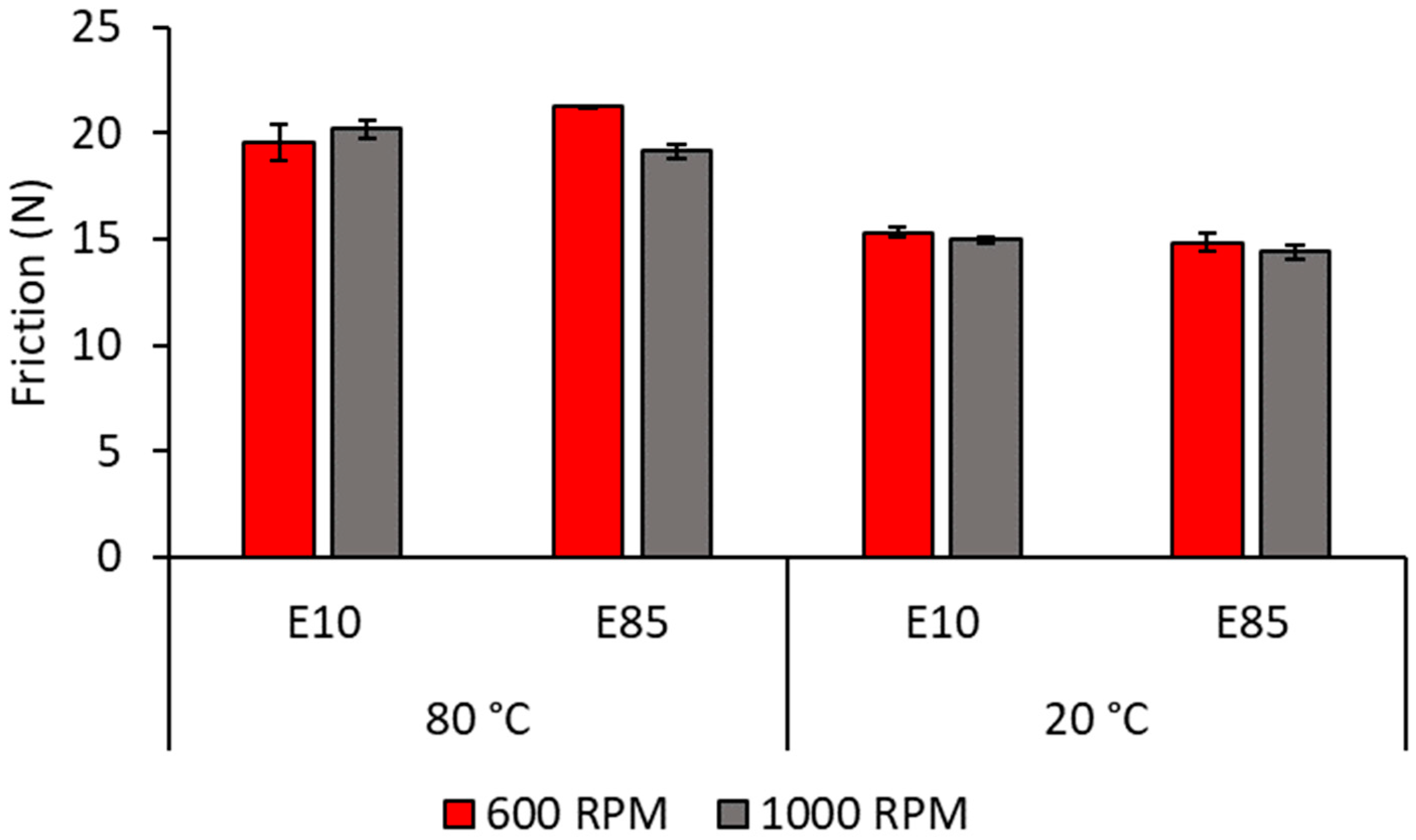
The measured ring friction is taken at two chosen contact temperatures of 20 °C and 80 °C, two speeds: 600 and 800 RPM, and with 2.5% E10 lubricant dilution and 2.5% E85 lubricant dilution. The mean oil control ring–cylinder liner experimentally measured friction for each of these cases is shown in Figure 3.
In Figure 3, friction is shown to be higher at 80 °C because of a reduction in lubricant viscosity with temperature, reducing its load carrying capacity. This leads to increased direct boundary interactions, and thus, friction. The difference observed between lubricant action diluted with E10 and E85 is shown to be fairly small. Therefore, a negligible effect on oil control ring–cylinder liner friction would be expected in progressing from the use of E10 fuel to E85. Cousseau et al. [24] and Ajayi et al. [16] found similar results during their experimental investigations considering E10 and E100, and E10 fuel dilution, respectively. Cousseau et al. [24] noticed, however, a significant difference between the undiluted and diluted lubricant.
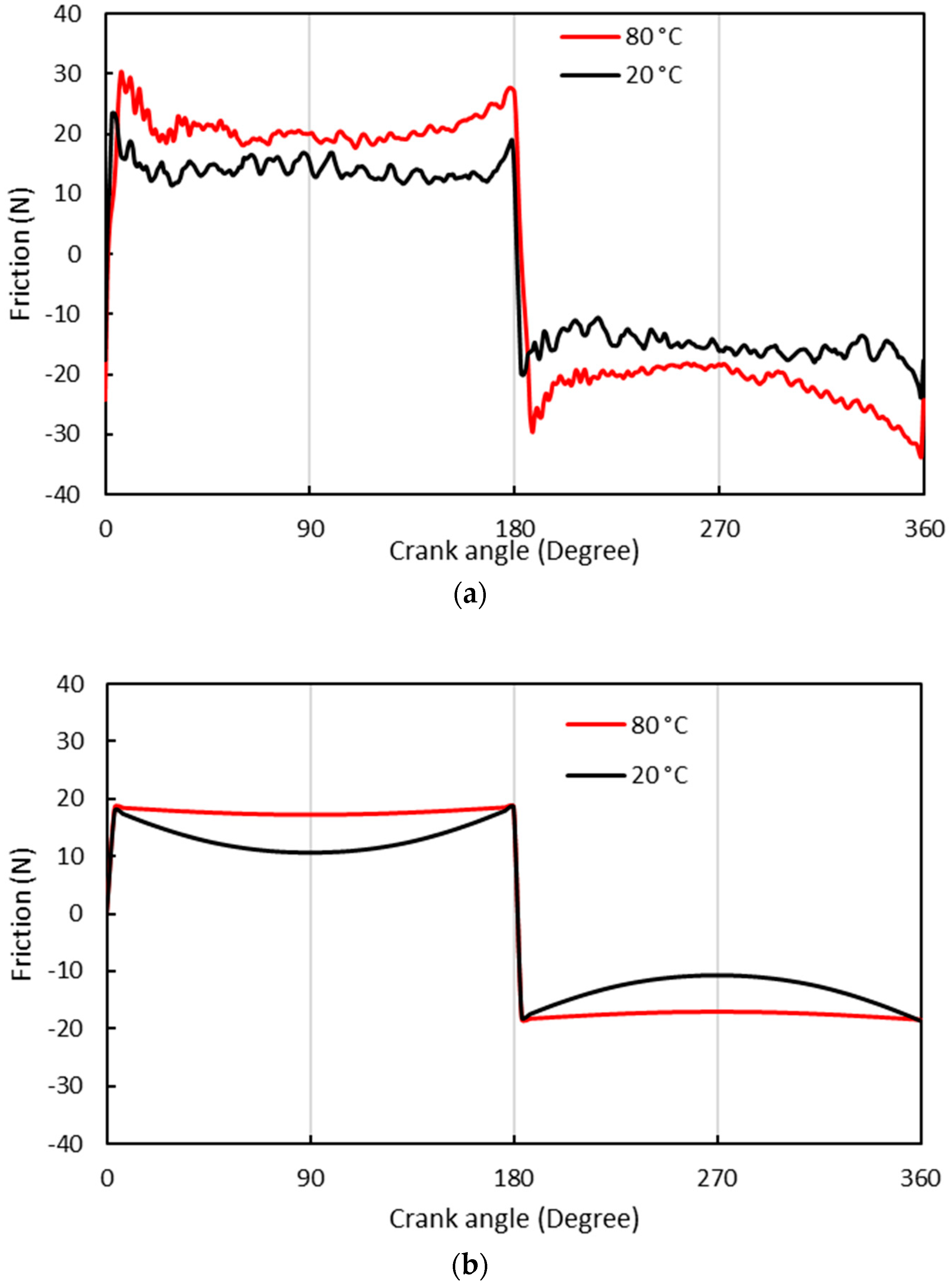
Figure 4a highlights the differences in the measured frictional behaviour between the 0W-40 lubricant containing 2.5% E85 at 20 °C and 80 °C, while Figure 4b shows the predicted differences at two studied temperatures.
From Figure 4, it is clear that at 20 °C, a significant reduction in friction at mid-stroke occurs, which is because of high entrainment speeds leading to increased film thickness. At 80 °C, the viscosity of the lubricant decreased by an order of magnitude (see Figure 2), resulting in very limited hydrodynamic load carrying capacity. Since the model does not include the effect of generated heat in the contact and hydrodynamic squeeze film effect, some details of piston reversal [32] are not fully captured. It is proposed that the asymmetry at about the midpoint of each stroke’s experimental friction data is not captured in the analytical analysis, as the squeeze film effect is not included. However, the model demonstrates an ability to capture the key aspects of frictional behaviour and highlights the importance of thermal effects in determining oil control ring–cylinder liner friction.
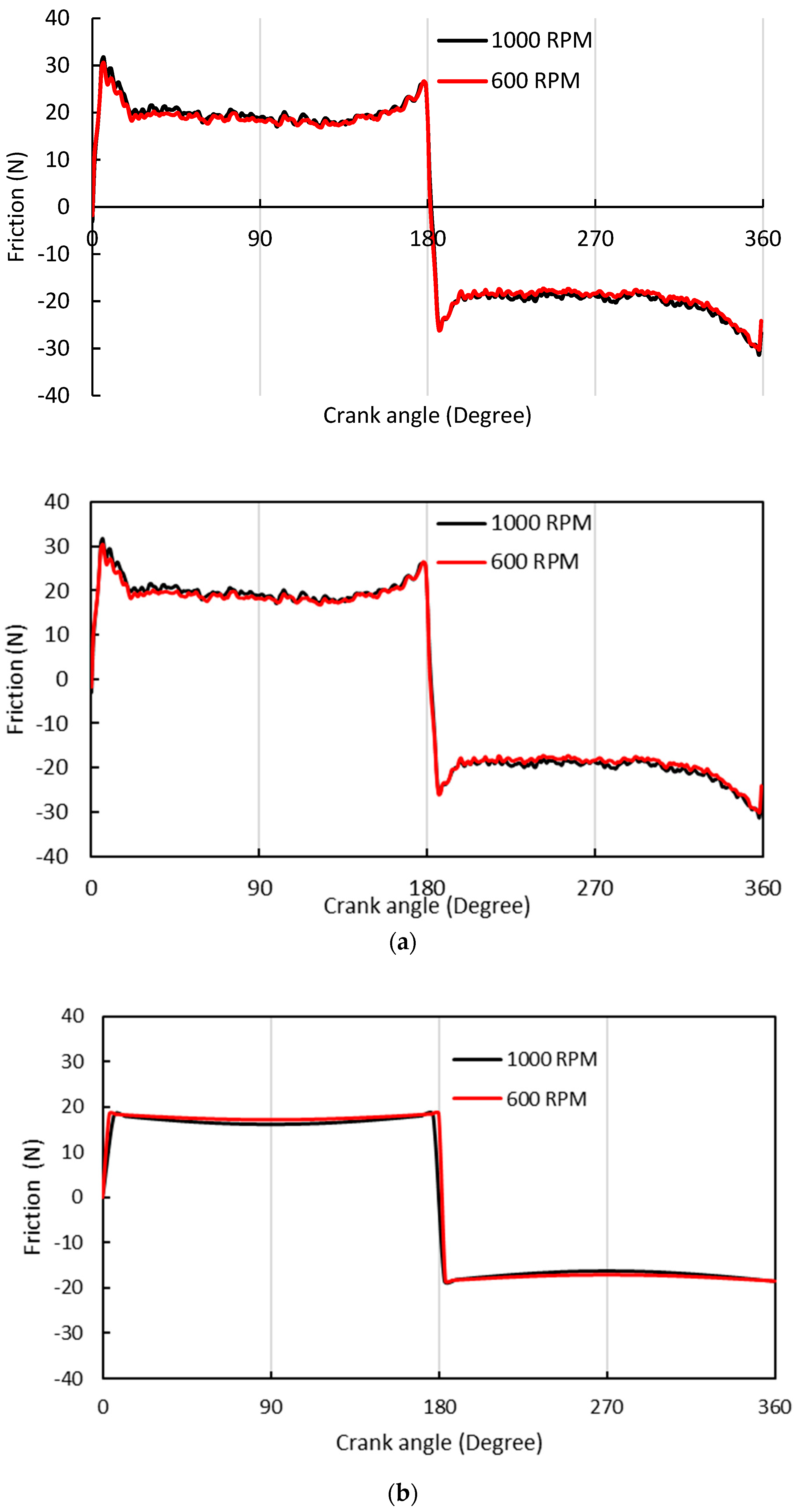
Figure 5a,b depict the experimentally measured and numerically predicted results for the lubricant diluted by 2.5% E10 at crank speeds of 600 and 1000 RPM. Both the experimental and numerical results indicate very little differences in frictional behaviour.
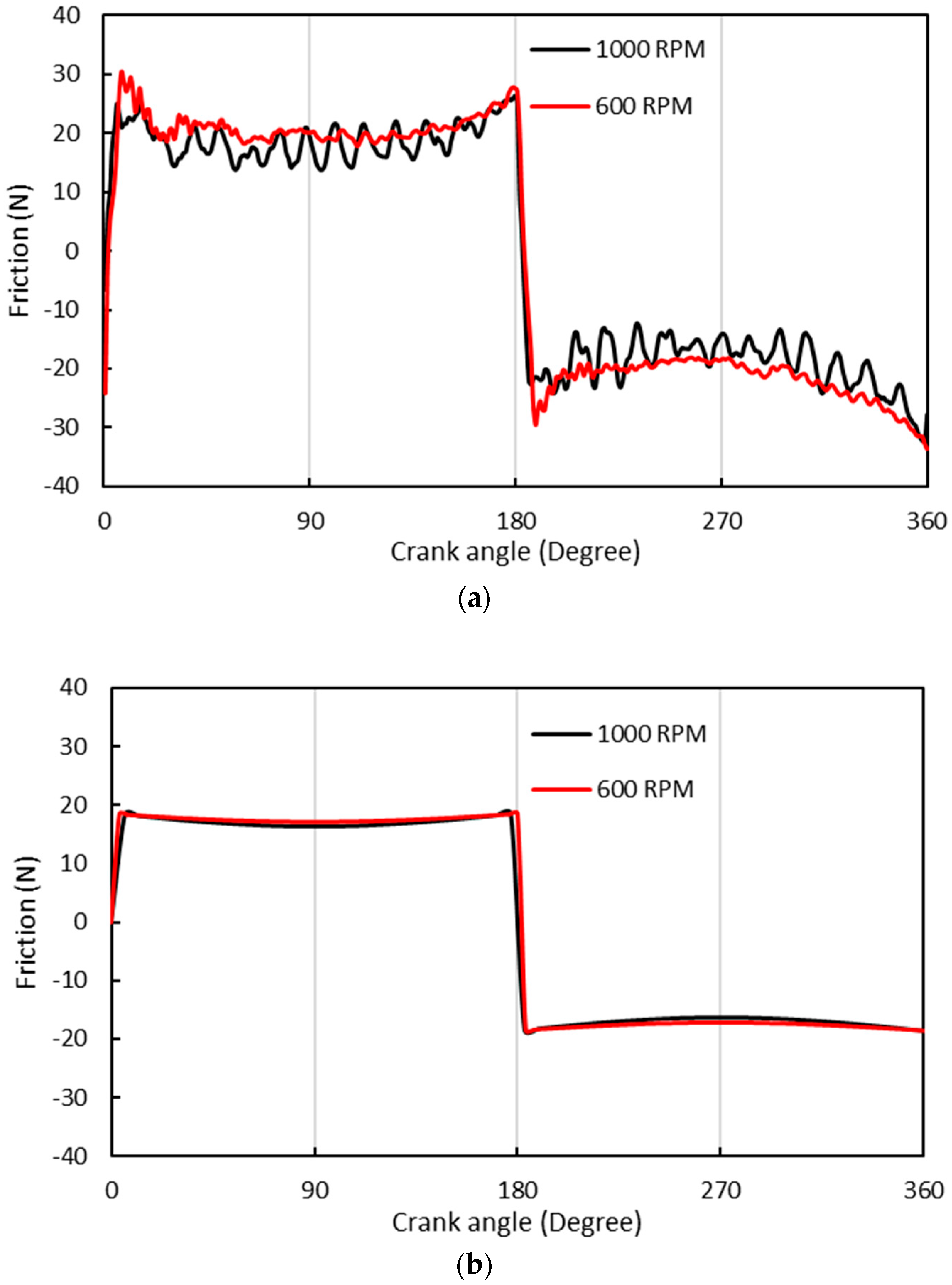
Figure 6a,b show the measured and predicted results for the lubricant diluted by 2.5% E85. The measured results indicate that there is very little difference in the generated friction between test speeds. However, at 1000 RPM, there is a reduction in mid-stroke friction, as would be expected, because of an increase in hydrodynamic entrainment. A similar, although less pronounced result is also shown in the predicted results. The results shown in Figure 5 and Figure 6 for lubricants contaminated with both E10 and E85 show very similar frictional behaviours. Lenauer et al. [22] also observed very similar frictional coefficients for neat modern fully formulated synthetic lubricants and those contaminated with ethanol combustion products.

4. Conclusions

This paper presents a combined experimental and analytical investigation of the generated friction in a three-piece oil control ring–cylinder liner conjunction under a prevailing mixed-hydrodynamic regime of lubrication. The measurements are obtained through the use of a novel bespoke cylindrical shape tribometer, and the principles of its operation are fully described. The measurements show that the oil ring–liner conjunction traverses through boundary and mixed regimes of lubrication. This study also considers the role of lubricants, diluted by fuels containing different percentages of ethanol, as there is a growing trend in the use of such fuel mixtures. The study shows that the transition from E10 to E85 has an insignificant effect on the friction generated in the oil control ring conjunction. This is an important finding and is supported by the results from a detailed analytical model.

Author Contributions

Conceptualization: all; numerical methodology: N.M., N.D., R.R. and H.R.; software: N.M., N.D. and R.R.; experimentation: S.B., M.F. and S.H.-S.; validation: all; investigation/analysis: all; data curation: N.M. and S.B.; original drafting and writing: N.M., N.D., R.R. and H.R.; final review and editing: all; supervision: P.K. and H.R. All authors have read and agreed to the published version of the manuscript.

Funding

Authors wish to express their gratitude to the Engineering and Physical Sciences Research Council (EPSRC) Doctoral training partnership (EP/N509516/1) and Capricorn Automotive for Financial support extended to this research project.

Data Availability Statement

The data presented in this study are available on request from the corresponding author.

Conflicts of Interest

S. Howell-Smith was employed by Capricorn Automotive Ltd. (Basingstoke, UK). The remaining authors declare that the research was conducted in the absence of any commercial or financial relationships that could be construed as a potential conflict of interest.

Nomenclature

Roman symbols:
A a Real contact area
b Ring contact half-width
E 1,2 Young’s Moduli of elasticity of contacting surfaces
f f Total contact friction
f f , b Boundary friction
f f , v Viscous contact friction
h Lubricant film thickness
h m Minimum film thickness
L Ring circumferential length
R Ring crown radius
r Crank-pin radius
t Time
U Sliding velocity
W a Load carried by asperity interactions
W h Hydrodynamic contact reaction
W t Total contact load
x Axial direction (direction of lubricant entraining motion)
Greek symbols:
β a Average asperity tip radius
η Dynamic viscosity of the lubricant
η a Asperity density per unit area
λ m Stribeck’s oil film parameter
ν 1,2 Poisson’s ratio of contacting solids
μ Coefficient of friction
σ Root mean square roughness of counter faces
τ 0 Characteristic shear stress of the lubricant
ω Angular velocity
ξ Coefficient of boundary shear strength of asperities

References

  1. Profito, F.J.; Tomanik, E.; Zachariadis, D.C. Effect of cylinder liner wear on the mixed lubrication regime of TLOCRs. Tribol. Int. 2016, 93, 723–732. [Google Scholar] [CrossRef]
  2. Söderfjäll, M.; Almqvist, A.; Larsson, R. A model for twin land oil control rings. Tribol. Int. 2016, 95, 475–482. [Google Scholar] [CrossRef]
  3. Söderfjäll, M.; Almqvist, A.; Larsson, R. Component test for simulation of piston ring–cylinder liner friction at realistic speeds. Tribol. Int. 2016, 104, 57–63. [Google Scholar] [CrossRef]
  4. Liu, Y.; Kim, D.; Westerfield, Z.; Meng, Z.; Tian, T. A comprehensive study of the effects of honing patterns on twin-land oil control rings friction using both a numerical model a floating liner engine. Proc. Inst. Mech. Eng. Part J J. Eng. Tribol. 2019, 233, 229–255. [Google Scholar] [CrossRef]
  5. Westerfield, Z.; Tian, T.; Liu, Y.; Kim, D. A study of the friction of oil control rings using the floating liner engine. SAE Int. J. Engines 2016, 9, 1807–1824. [Google Scholar] [CrossRef]
  6. Kikuhara, K.; Koeser, P.S.; Tian, T. Effects of a cylinder liner microstructure on lubrication condition of a twin-land oil control ring and a piston skirt of an internal combustion engine. Tribol. Lett. 2022, 70, 1–15. [Google Scholar] [CrossRef]
  7. Tian, T.; Wong, V.W.; Heywood, J.B. Modeling the dynamics and lubrication of three piece Oil control rings is internal combustion engines. SAE Trans. 1998, 107, 1989–2006. [Google Scholar]
  8. Zhang, W.; Ahling, S.; Tian, T. Modeling the Three Piece Oil Control Ring Dynamics and Oil Transport in Internal Combustion Engines; SAE Technical Paper No. 2021-01-0345; SAE International: Warrendale, PA, USA, 2021. [Google Scholar]
  9. Li, M.; Tian, T. Effect of blowby on the leakage of the three-piece oil control ring and subsequent oil transport in upper ring-pack regions in internal combustion engines. Lubricants 2022, 10, 250. [Google Scholar] [CrossRef]
  10. Mochizuki, K.; Sasaki, R.; Iijima, N.; Usui, M. Prediction and Experimental Verification for Oil Transport Volume around Three-Piece Type Oil Control Ring Affecting Lubricating Oil Consumption. SAE Int. J. Adv. Curr. Pract. Mobil. 2022, 5, 595–609. [Google Scholar] [CrossRef]
  11. Tomlinson, K.; Davison, S.; King, P.; Howell-Smith, S.; Slatter, T.; Morris, N. On the Role of Friction Modifier Additives in the Oil Control Ring and Piston Liner Contact. J. Tribol. 2024, 146, 042201. [Google Scholar] [CrossRef]
  12. Cheng, W.K.; Hamrin, D.; Heywood, J.B.; Hochgreb, S.; Min, K.; Norris, M. An Overview of Hydrocarbon Emissions Mechanisms in Spark-Ignition Engines; SAE International: Warrendale, PA, USA, 1993. [Google Scholar]
  13. Tung, S.C.; Gao, H. Tribological investigation of piston ring coatings operating in an alternative fuel and engine oil blend. Tribol. Trans. 2002, 45, 381–389. [Google Scholar] [CrossRef]
  14. Tung, S.C.; Gao, H. Tribological characteristics and surface interaction between piston ring coatings and a blend of energy-conserving oils and ethanol fuels. Wear 2003, 255, 1276–1285. [Google Scholar] [CrossRef]
  15. Costa, H.L.; Cousseau, T.; Souza, R.M. Current knowledge on friction, lubrication, and wear of ethanol-fuelled engines—A review. Lubricants 2023, 11, 292. [Google Scholar] [CrossRef]
  16. Ajayi, O.O.; Lorenzo-Martin, C.; Fenske, G.; Corlett, J.; Murphy, C.; Przesmitzki, S. Bioderived fuel blend dilution of marine engine oil and impact on friction and wear behavior. J. Tribol. 2016, 138, 021603. [Google Scholar] [CrossRef]
  17. dos Santos, R.M.; Alves, S.M. Effect of fuel contamination on tribological properties of flex-fuel engines lubricating oils. Surf. Topogr. Metrol. Prop. 2022, 10, 044004. [Google Scholar] [CrossRef]
  18. Khuong, L.S.; Masjuki, H.H.; Zulkifli, N.W.M.; Mohamad, E.N.; Kalam, M.A.; Alabdulkarem, A.; Arslan, A.; Mosarof, M.H.; Syahir, A.Z.; Jamshaid, M. Effect of gasoline–bioethanol blends on the properties and lubrication characteristics of commercial engine oil. RSC Adv. 2017, 7, 15005–15019. [Google Scholar] [CrossRef]
  19. De Silva, P.R.; Priest, M.; Lee, P.M.; Coy, R.C.; Taylor, R.I. Tribometer investigation of the frictional response of piston rings when lubricated with the separated phases of lubricant contaminated with the gasoline engine biofuel ethanol and water. Tribol. Lett. 2011, 43, 107–120. [Google Scholar] [CrossRef]
  20. Costa, H.L.; Spikes, H.A. Impact of ethanol on the formation of antiwear tribofilms from engine lubricants. Tribol. Int. 2016, 93, 364–376. [Google Scholar] [CrossRef]
  21. Costa, H.L.; Evangelista, K.S.; Cousseau, T.; Acero, J.S.R.; Kessler, F. Use of XANES and XPS to investigate the effects of ethanol contamination on anti-wear ZDDP tribofilms. Tribol. Int. 2021, 159, 106997. [Google Scholar] [CrossRef]
  22. Lenauer, C.; Tomastik, C.; Wopelka, T.; Jech, M. Piston ring wear and cylinder liner tribofilm in tribotests with lubricants artificially altered with ethanol combustion products. Tribol. Int. 2015, 82, 415–422. [Google Scholar] [CrossRef]
  23. Banerji, A.; Lukitsch, M.J.; Alpas, A.T. Friction reduction mechanisms in cast iron sliding against DLC: Effect of biofuel (E85) diluted engine oil. Wear 2016, 368, 196–209. [Google Scholar] [CrossRef]
  24. Cousseau, T.; Acero, J.S.R.; Sinatora, A. Tribological response of fresh and used engine oils: The effect of surface texturing, roughness and fuel type. Tribol. Int. 2016, 100, 60–69. [Google Scholar] [CrossRef]
  25. Hamdan, S.H.; Chong, W.W.F.; Ng, J.H.; Chong, C.T.; Rajoo, S. A study of the tribological impact of biodiesel dilution on engine lubricant properties. Process Saf. Environ. Prot. 2017, 112, 288–297. [Google Scholar] [CrossRef]
  26. Forder, M.D.; Morris, N.; King, P.; Balakrishnan, S.; Howell-Smith, S. An experimental investigation of low viscosity lubricants on three piece oil control rings cylinder liner friction. Proc. Inst. Mech. Eng. Part J J. Eng. Tribol. 2022, 236, 2261–2271. [Google Scholar] [CrossRef]
  27. Haddad, S.D.; Tjan, K.T. An analytical study of offset piston and crankshaft designs and the effect of oil film on piston slap excitation in a diesel engine. Mech. Mach. Theory 1995, 30, 271–284. [Google Scholar] [CrossRef]
  28. Gohar, R.; Rahnejat, H. Fundamentals of Tribology, 3rd ed.; World Scientific: Singapore, 2018. [Google Scholar]
  29. Furuhama, S.; Takiguchi, M.; Tomizawa, K. Effect of piston and piston ring designs on the piston friction forces in diesel engines. SAE Trans. 1981, 3018–3030. [Google Scholar]
  30. Greenwood, J.A.; Tripp, J.H. The contact of two nominally flat rough surfaces. Proc. Inst. Mech. Eng. J. Mech. Eng. Sci. 1970, 185, 625–633. [Google Scholar] [CrossRef]
  31. Gore, M.; Morris, N.; Rahmani, R.; Rahnejat, H.; King, P.D.; Howell-Smith, S. A combined analytical-experimental investigation of friction in cylinder liner inserts under mixed and boundary regimes of lubrication. Lubr. Sci. 2017, 29, 293–316. [Google Scholar] [CrossRef]
  32. Dolatabadi, N.; Forder, M.; Morris, N.; Rahmani, R.; Rahnejat, H.; Howell-Smith, S. Influence of advanced cylinder coatings on vehicular fuel economy and emissions in piston compression ring conjunction. Appl. Energy 2020, 259, 114129. [Google Scholar] [CrossRef]
  33. Leighton, M.; Morris, N.; Rahmani, R.; Rahnejat, H. Surface specific asperity model for prediction of friction in boundary and mixed regimes of lubrication. Meccanica 2017, 52, 21–33. [Google Scholar] [CrossRef]
  34. Dolatabadi, N.; Rahmani, R.; Rahnejat, H.; Garner, C.P.; Brunton, C. Performance of poly alpha olefin nanolubricant. Lubricants 2020, 8, 17. [Google Scholar] [CrossRef]
  35. Rahmani, R.; Rahnejat, H. Enhanced performance of optimised partially textured load bearing surfaces. Tribol. Int. 2018, 117, 272–282. [Google Scholar] [CrossRef]
  36. Eyring, H. The activated complex in chemical reactions. J. Chem. Phys. 1935, 3, 107–115. [Google Scholar] [CrossRef]
  37. Briscoe, B.J.; Evans, D.C.B. The shear properties of Langmuir-blodgett layers. Proc. Roy. Soc. Lond. Ser. A Math. Phys. Sci. 1982, 380, 389–407. [Google Scholar]
  38. Frottier, V.; Heywood, J.B.; Hochgreb, S. Measurement of gasoline absorption into engine lubricating oil. SAE Trans. 1996, 1114–1121. [Google Scholar]
  39. Smith, O.M.E. In-Cylinder Fuel and Lubricant Effects on Gasoline Engine Friction. Ph.D. Dissertation, University of Leeds, Leeds, UK, 2007. [Google Scholar]
  40. Shayler, P.J.; Winborn, L.D.; Scarisbrick, A. The Build-Up of Oil Dilution by Gasoline and the Influence of Vehicle Usage Pattern; SAE Technical Paper 2000-01-2838; SAE International: Warrendale, PA, USA, 2000. [Google Scholar]
  41. Kollman, K.; Gürtler, T.; Land, K.; Warnecke, W.; Müller, H.D. Extended Oil Drain Intervals—Conservation of Resources or Reduction of Engine Life (Part II). SAE Trans. 1998, 107, 738–758. [Google Scholar]
  42. Bergstra, R.J.; Givens, W.A.; Maxwell, W.L.; Richman, W.H. Advanced Synthetic Passenger Vehicle Engine Oils for Extended Oil Drain Performance. SAE Trans. 1998, 107, 759–772. [Google Scholar]
  43. Taylor, R.I. Fuel-lubricant interactions: Critical review of recent work. Lubricants 2021, 9, 92. [Google Scholar] [CrossRef]
  44. Colli, G.B.; Castejon, D.; Salvetti, A.; Volpato, O. Heated Injector Cold Start System for Flex-Fuel Motorcycles; SAE Technical Paper No. 2010-36-0156; SAE International: Warrendale, PA, USA, 2010. [Google Scholar]
  45. Huang, Y.; Huang, S.; Huang, R.; Hong, G. Spray and evaporation characteristics of ethanol and gasoline direct injection in non-evaporating, transition and flash-boiling conditions. Energy Convers. Manag. 2016, 108, 68–77. [Google Scholar] [CrossRef]
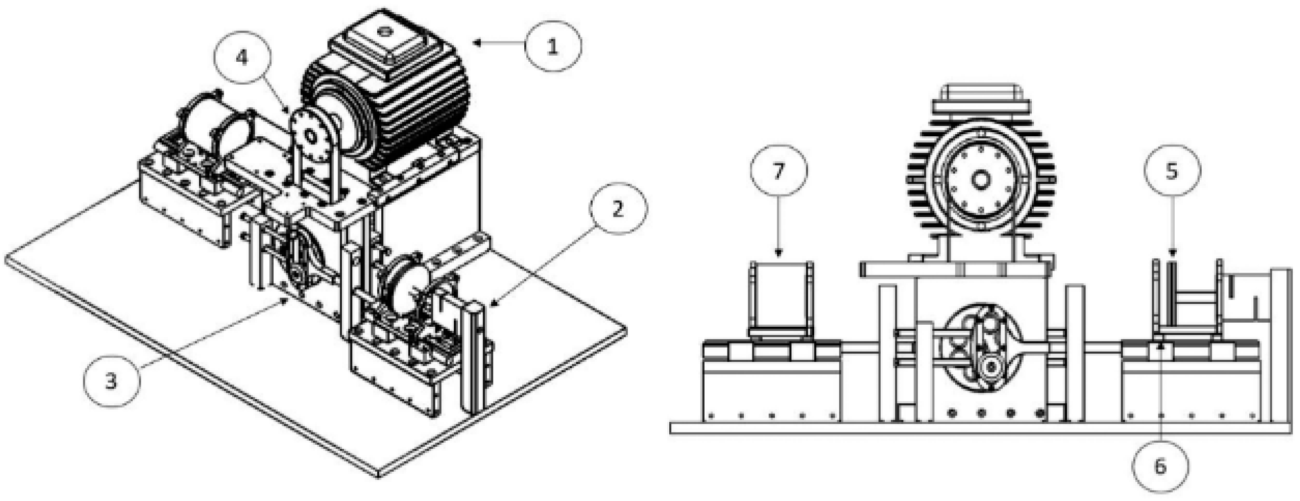
Figure 1. Schematics of test rig design. This figure is reproduced under the terms of the Creative Commons Attribution 4.0 License (https://creativecommons.org/licenses/by/4.0/, accessed on 26 March 2024) from original articles by Forder et al. [26].
Lubricants 12 00150 g001
Figure 2. Viscosity data for 0W-40 and E10 and E85 based on data provided by Coli et al. [44] and Huang et al. [45].
Lubricants 12 00150 g002
Figure 3. Comparison of experimentally measured average friction for fuel-diluted lubricant by different percentage ethanol content at 20 °C and 80 °C.
Lubricants 12 00150 g003
Figure 4. Temperature effect on generated friction for 0W−40 with 2.5% E85 dilution at 600 RPM: (a) experimentally measured, and (b) analytically predicted.
Lubricants 12 00150 g004
Figure 5. Generated friction variation with crank speed for 0W-40 diluted by 2.5% E10 at 80 °C: (a) experimentally measure, and (b) analytically predicted.
Lubricants 12 00150 g005
Figure 6. Comparison of the role of speed in friction data for 0W-40 lubricant diluted by 2.5% E85 at 80 °C: (a) experimentally measured, and (b) analytically predicted.
Lubricants 12 00150 g006
Table 3. Lubricant rheology (0W-40).
ParameterValueUnit
Density855 @15 °Ckg·m−3
Kinematic viscosity67.61 @40 °C, 12.25 @100 °CcSt
Pressure–viscosity coefficient10GPa−1
Characteristic shear stress2MPa
Table 4. Fuel specifications [44,45].
ParameterValueUnit
Dynamic viscosity E10 0.56   @ 20   mPa·s
Dynamic viscosity E85 1.04   @ 20   mPa·s
Dynamic viscosity E10 0.28   @ 80   mPa·s
Dynamic viscosity E85 0.41   @ 80   mPa·s
Disclaimer/Publisher’s Note: The statements, opinions and data contained in all publications are solely those of the individual author(s) and contributor(s) and not of MDPI and/or the editor(s). MDPI and/or the editor(s) disclaim responsibility for any injury to people or property resulting from any ideas, methods, instructions or products referred to in the content.