Effect of Substrate Preheating Temperature on the Microstructure and Properties of Laser Cladding Fe/TiC Composite Coating


Abstract
:1. Introduction
2. Materials and Methods
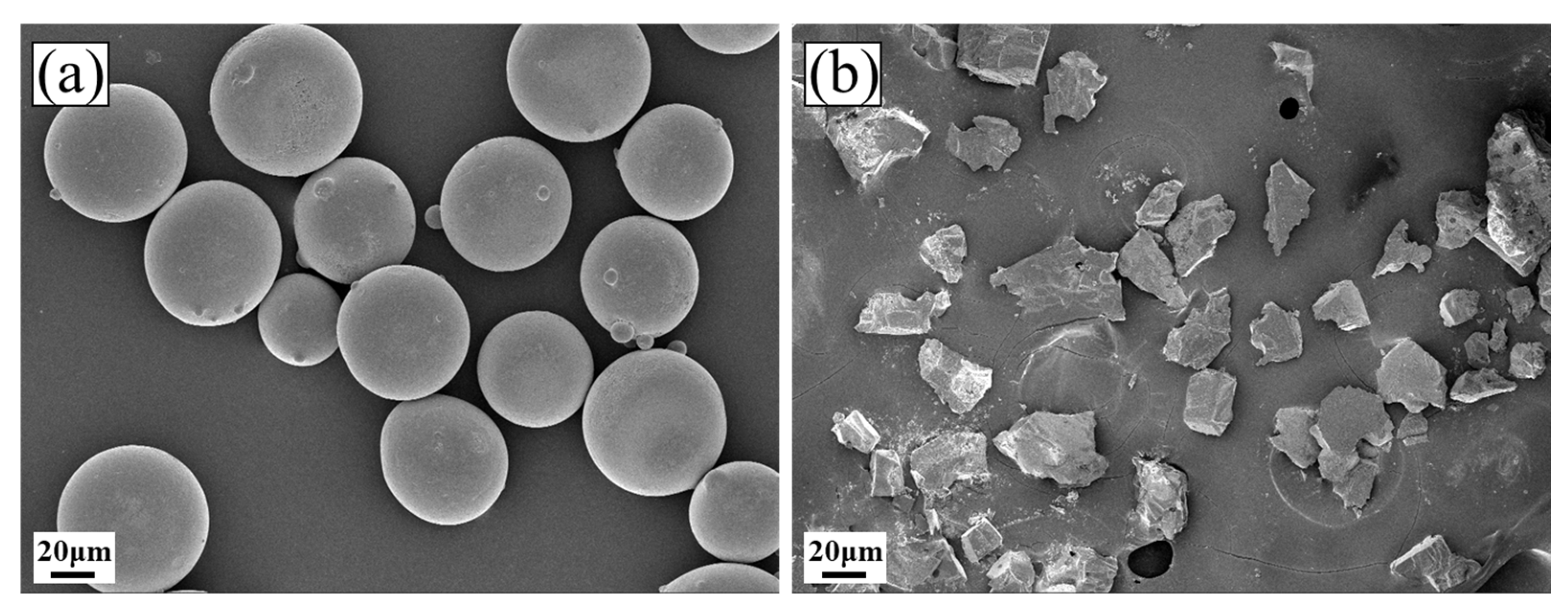
2.1. Materials
2.2. Laser Cladding Process Parameters
2.3. Analysis and Characterization Methods
3. Results and Discussion
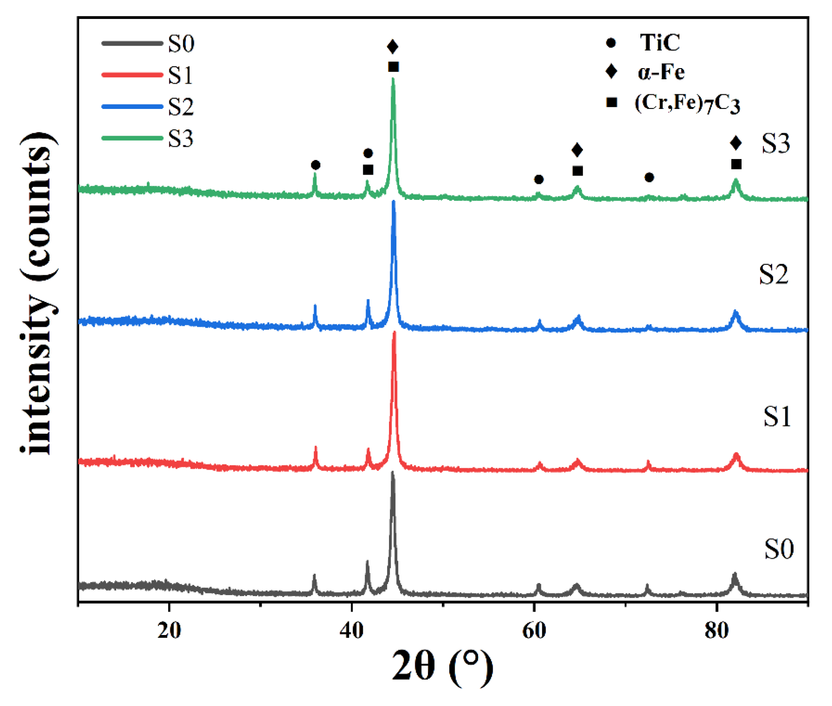
3.1. Phase Composition
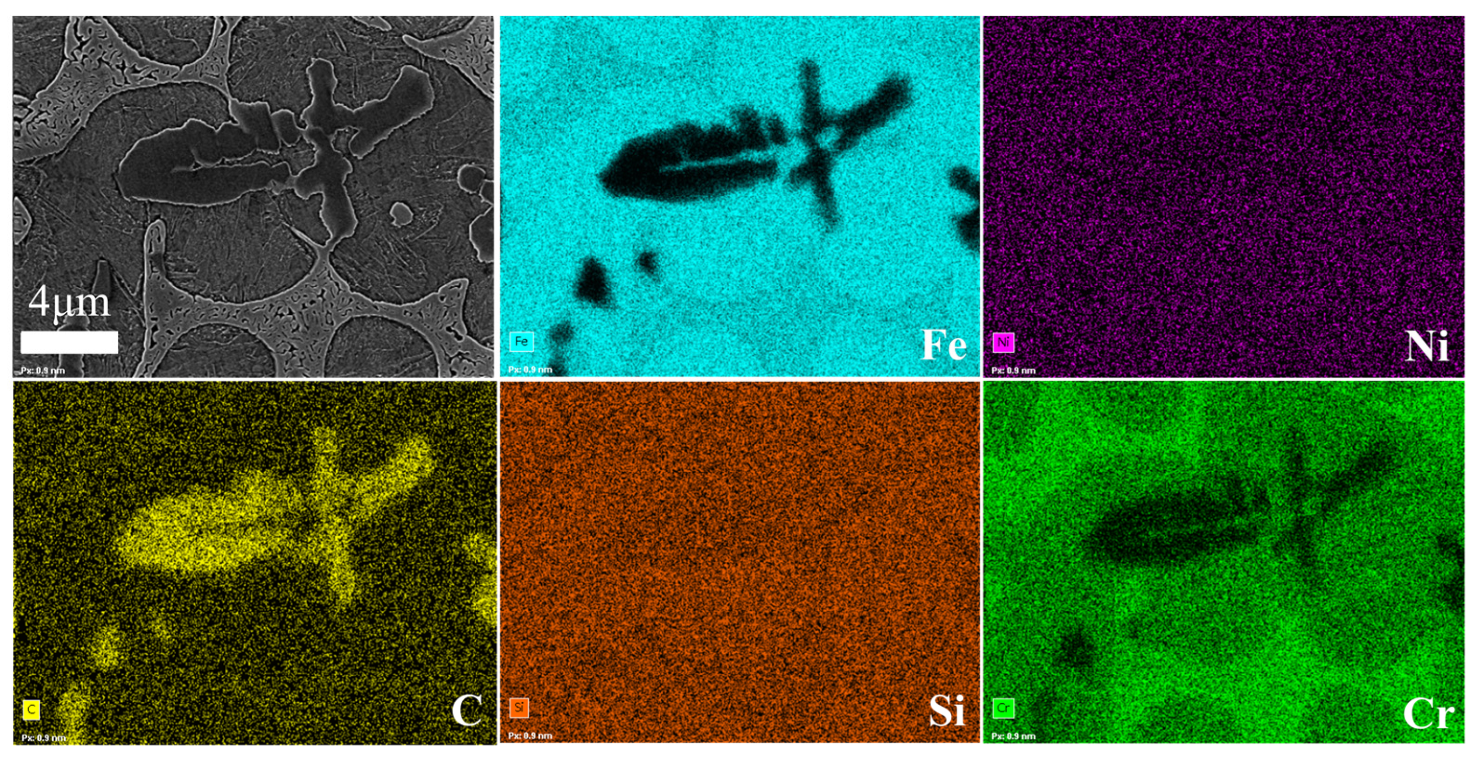
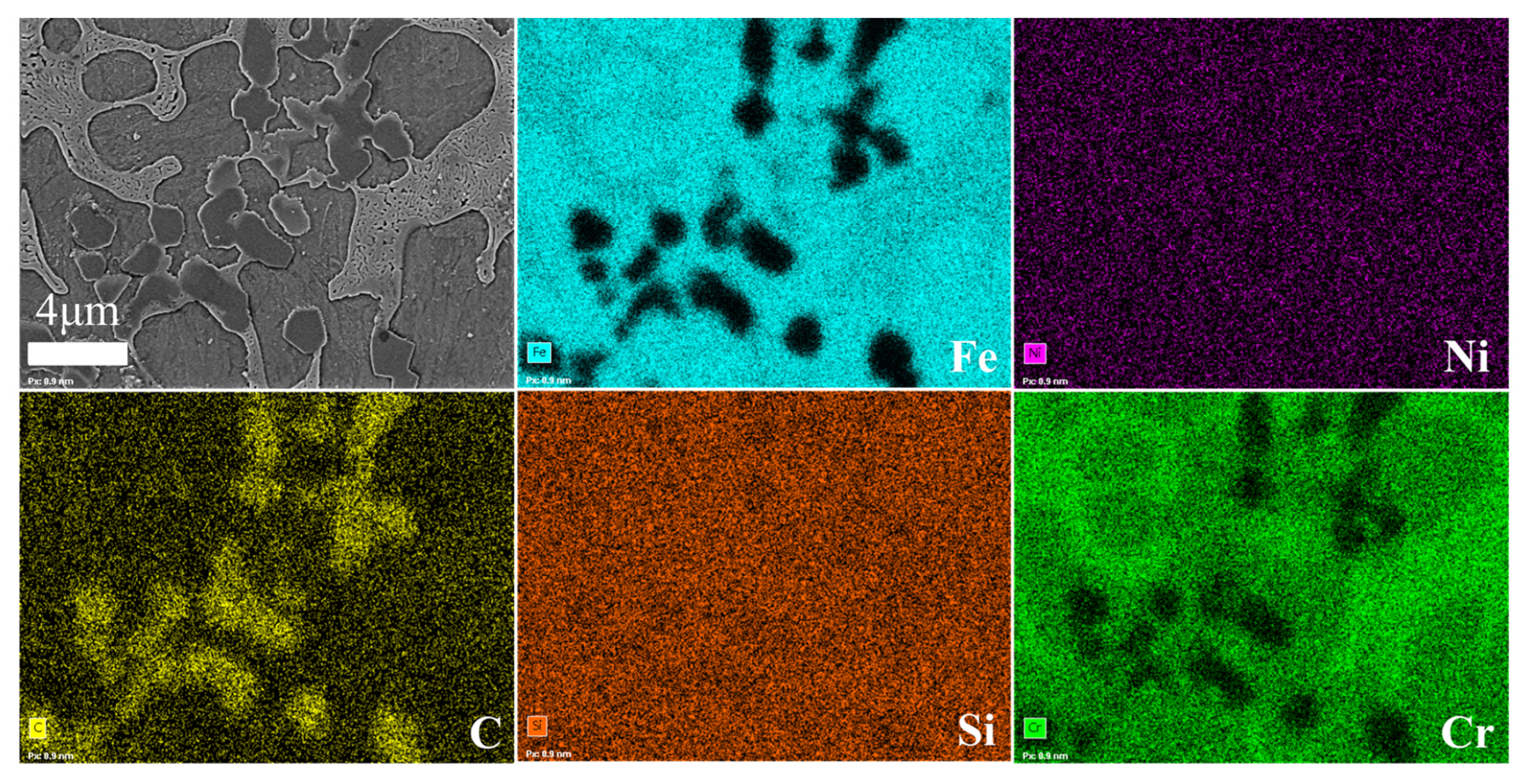
3.2. Microstructure
3.3. Microhardness
3.4. Wear Resistance
3.5. Electrochemical Corrosion
4. Conclusions
- (1)
- The cladding angle of the Fe/TiC composite coating initially increases and then decreases as the substrate preheating temperature rises. Specifically, the cladding angle increases from 130° to 148° and then decreases to 140°.
- (2)
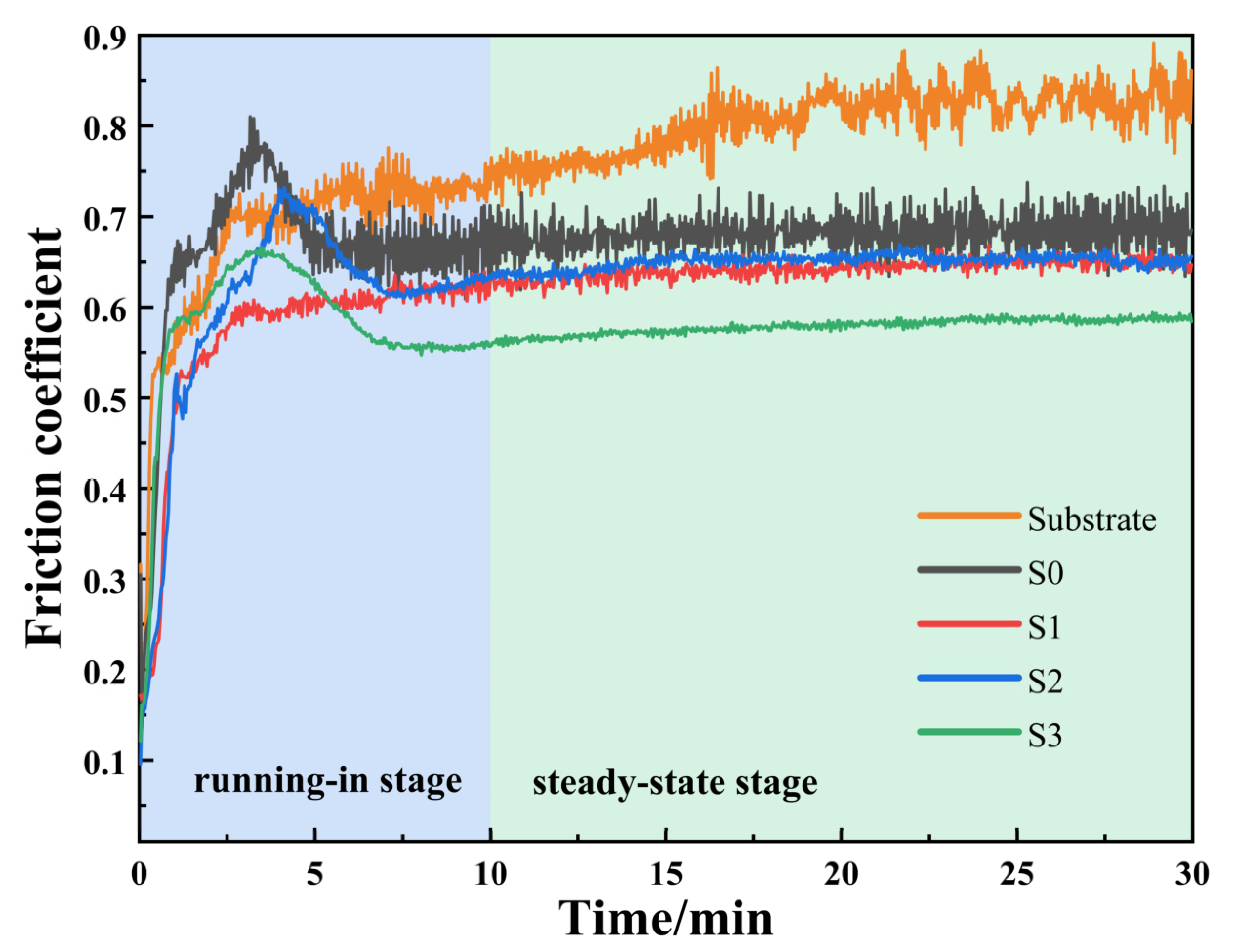
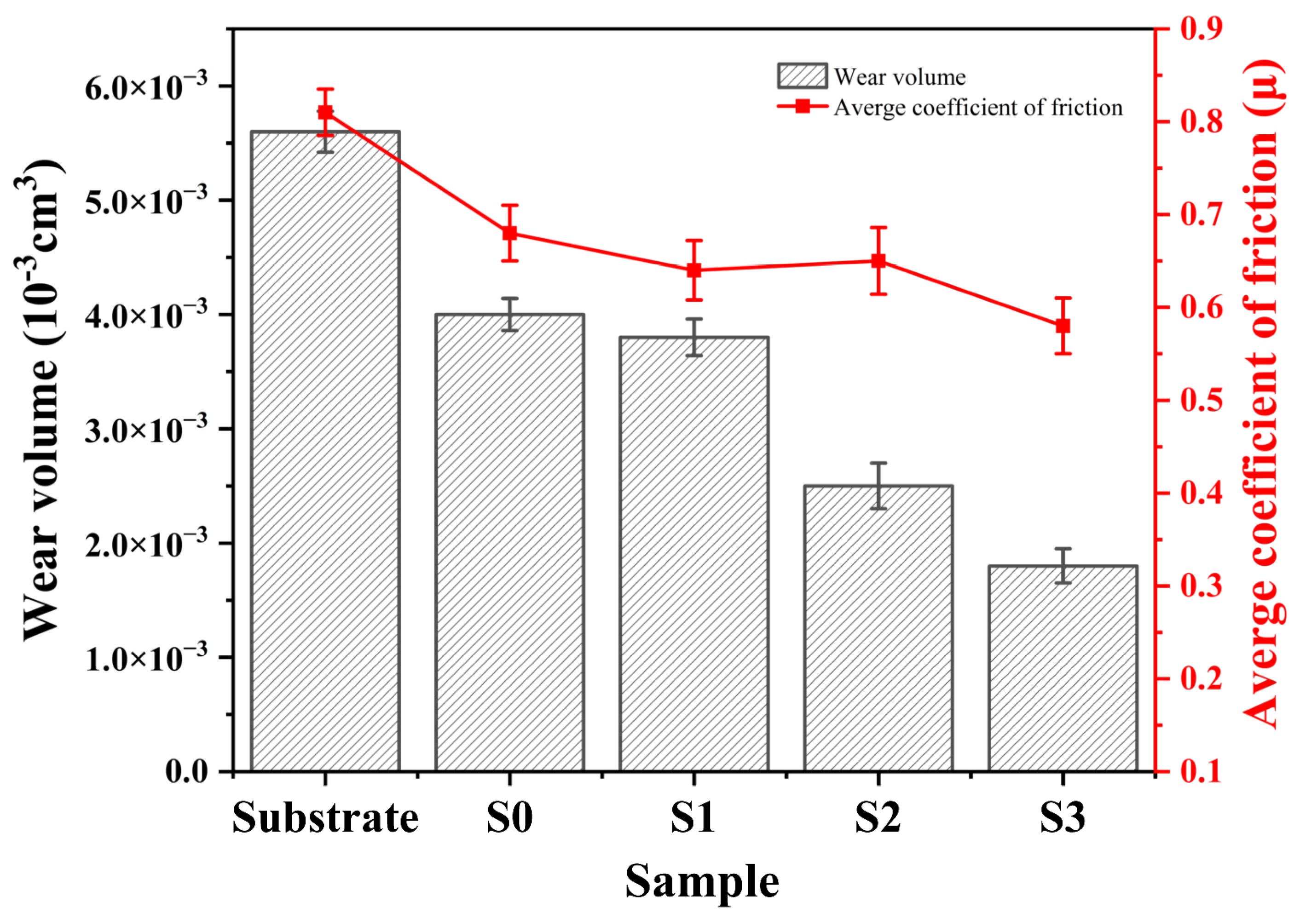
- The implementation of substrate preheating enhanced both the microhardness and wear resistance of the composite coating. Specifically, the microhardness of specimens subjected to substrate preheating exhibited an increase ranging from 50 to 100 HV compared with specimens processed at room temperature. The hardness and wear resistance properties of the coating are optimal at a substrate preheating temperature of 300 °C.
- (3)
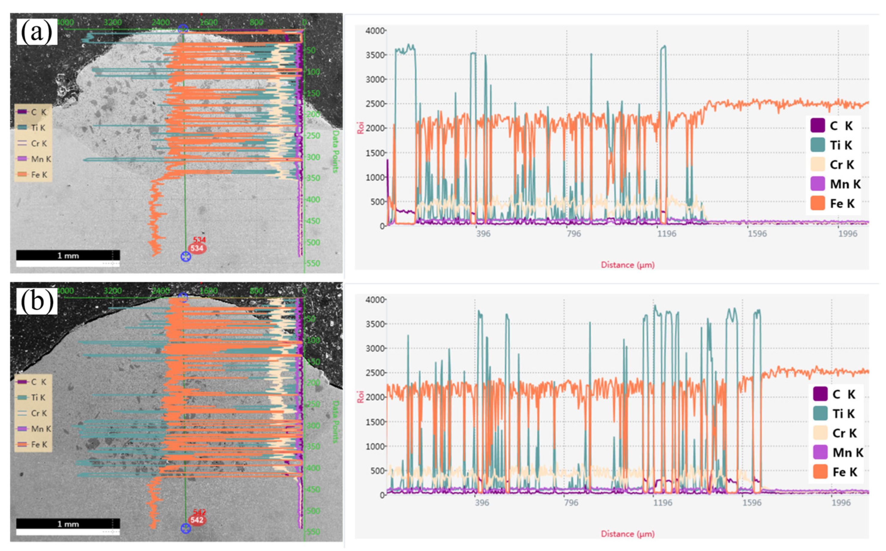
- The preheating temperature enhances the microstructure and compositional uniformity of the cladding layer by increasing the heat capacity of the substrate, thereby improving the wear and corrosion resistance of the cladding layer.
Author Contributions
Funding
Data Availability Statement
Conflicts of Interest
References
- Lu, Z.G.; Du, C.Y.; Chen, Q.C.; Niu, T.Y.; Wang, N.; Song, W.L. Wear and Friction Characteristics of 65mn Steel for Spike-Tooth Harrow. Coatings 2021, 11, 319. [Google Scholar] [CrossRef]
- Chen, K.Y.; Yang, X.F.; Li, W.Y.; Xia, G.F.; Wang, S.R.; Wang, K. Study on the Wear and Corrosion Resistance of Fe–Mo Coatings on 65mn Steel Ploughshares by Laser Cladding. Appl. Phys. A 2022, 128, 795. [Google Scholar] [CrossRef]
- Xin, W.; Feng, S.K.; Zhang, W.G. Microstructure, Phase Composition and Wear Properties of Iron-Based Gradient Coatings by Laser Cladding on 65mn Steel. Surf. Coat. Technol. 2024, 477, 130290. [Google Scholar]
- Li, J.W.; Tong, J.; Hu, B.; Ma, Y.H. Biomimetic Functional Surface of Reducing Soil Adhesion on 65mn Steel. Adv. Mech. Eng. 2019, 11, 1687814019889801. [Google Scholar] [CrossRef]
- Sun, B.; Wang, Q.Q.; Chen, Y.X.; Cheng, J.B.; Zhao, H.C.; Zhu, S.S.; Zhang, B.S.; Liang, X.B.; Shen, B.L. Dendrite Refinement and Wear Performance Enhancement in Laser-Cladded Fe-Based Coatings after Multi-Step Laser Remelting. Surf. Coat. Technol. 2022, 447, 128794. [Google Scholar] [CrossRef]
- Daram, P.; Banjongprasert, C. The Influence of Post Treatments on the Microstructure and Corrosion Behavior of Thermally Sprayed Nicrmoal Alloy Coating. Surf. Coat. Technol. 2020, 384, 125166. [Google Scholar] [CrossRef]
- Ryabchikov, A.I.; Kashkarov, E.B.; Shevelev, A.E.; Syrtanov, M.S. High-Intensity Chromium Ion Implantation into Zr-1nb Alloy. Surf. Coat. Technol. 2020, 383, 125272. [Google Scholar] [CrossRef]
- Vernardou, D. Special Issue: Advances in Chemical Vapor Deposition. Materials 2020, 13, 4167. [Google Scholar] [CrossRef] [PubMed]
- Zhang, Q.; Han, B.; Li, M.Y.; Chen, Z.B.; Hu, C.Y.; Jia, C.X. Comparison of Cocrfeni Coatings Prepared Via High-Speed Laser Cladding and Normal Laser Cladding on Microstructure and Properties. Intermetallics 2023, 153, 107795. [Google Scholar] [CrossRef]
- Zhang, Z.; Yu, T.; Kovacevic, R. Erosion and Corrosion Resistance of Laser Cladded Aisi 420 Stainless Steel Reinforced with Vc. Appl. Surf. Sci. 2017, 410, 225–240. [Google Scholar] [CrossRef]
- Zhou, S.F.; Xu, Y.B.; Liao, B.Q.; Sun, Y.J.; Dai, X.Q.; Yang, J.X.; Li, Z.Y. Effect of Laser Remelting on Microstructure and Properties of Wc Reinforced Fe-Based Amorphous Composite Coatings by Laser Cladding. Opt. Laser Technol. 2018, 103, 8–16. [Google Scholar] [CrossRef]
- Liang, H.; Liu, J.H.; Sun, L.K.; Hou, J.X.; Cao, Z.Q. Optimization of the Forming Quality of a Laser-Cladded Alcrfeniw0.2 High-Entropy Alloy Coating. Coatings 2023, 13, 1744. [Google Scholar] [CrossRef]
- Singh, A.K.; Simant, K.; Dey, D.P.; Das, A.K.; Pal, A.R.; Pratihar, D.K.; Roy, A.C. Experimental Investigation and Parametric Optimization for Minimization of Dilution During Direct Laser Metal Deposition of Tungsten Carbide and Cobalt Powder Mixture on Ss304 Substrate. Powder Technol. 2021, 390, 339–353. [Google Scholar] [CrossRef]
- Sun, Y.W.; Hao, M.Z. Statistical Analysis and Optimization of Process Parameters in Ti6al4v Laser Cladding Using Nd:Yag Laser. Opt. Lasers Eng. 2012, 50, 985–995. [Google Scholar] [CrossRef]
- Mohsan, A.U.H.; Zhang, M.; Wang, D.F.; Zhao, S.; Wang, Y.S.; Chen, C.Y.; Zhang, J.H. State-of-the-Art Review on the Ultrasonic Vibration Assisted Laser Cladding (Uvalc). J. Manuf. Process. 2023, 107, 422–446. [Google Scholar] [CrossRef]
- Wang, Y.Y.; Shi, H.; Hao, X.H.; Liu, H.X.; Zhang, X.W. Microstructure and Wear Resistance of Fe60 Laser Cladding Coating Assisted by Steady Magnetic Field–Mechanical Vibration Coupling Field. Coatings 2022, 12, 751. [Google Scholar] [CrossRef]
- Zhai, L.L.; Ban, C.Y.; Zhang, J.W. Investigation on Laser Cladding Ni-Base Coating Assisted by Electromagnetic Field. Opt. Laser Technol. 2019, 114, 81–88. [Google Scholar] [CrossRef]
- Li, X.; Peng, J.H.; Wang, F.; Liu, Z.Z.; Feng, X.Y. Effect of Electrically Assisted Preheating on Microstructure and Properties of Laser-Cladded Co-Based Coating on Cp-Ti Alloy Substrate. Coatings 2023, 13, 1379. [Google Scholar] [CrossRef]
- Wang, J.Y.; Cui, X.F.; Zhao, Y.; Zhang, Y.; Fan, X.T.; Zha, M.R.; Jin, G. Microstructure and Performance Enhancement of the Tin/Fe-Based Cladding Layer Induced by Mechanical Vibration Assisted Underwater Wet Laser Cladding. Surf. Coat. Technol. 2024, 476, 130176. [Google Scholar] [CrossRef]
- Zhang, G.T.; Liu, W.J.; Bian, H.Y.; Xing, F.; Xu, X.W. Effect of Substrate Preheating on Cracking and Wear Resistance of Laser-Cladded Tribaloy T-800 Coatings on Dd5 Single-Crystal Alloy. J. Therm. Spray Technol. 2024, 33, 1027–1039. [Google Scholar]
- Hebbale, A.M.; Manish, T.; Ravi, B. Microstructural Studies of Composite (Cr3C2–Nicr) Laser Clads Developed on Preheated Substrate T91. Trans. Indian Inst. Met. 2021, 74, 593–600. [Google Scholar] [CrossRef]
- Farahmand, P.; Liu, S.; Zhang, Z.; Kovacevic, R. Laser Cladding Assisted by Induction Heating of Ni–Wc Composite Enhanced by Nano-Wc and La2O3. Ceram. Int. 2014, 40 Pt A, 15421–15438. [Google Scholar] [CrossRef]
- Wang, H.Z.; Cheng, Y.H.; Yang, J.Y.; Liang, X.B. Microstructure and Properties of Fe Based Amorphous Coatings Deposited by Laser Cladding under Different Preheating Temperatures. J. Non-Cryst. Solids 2023, 602, 122081. [Google Scholar] [CrossRef]
- Bidron, G.; Doghri, A.; Malot, T.; Fournier-dit-Chabert, F.; Thomas, M.; Peyre, P. Reduction of the Hot Cracking Sensitivity of Cm-247lc Superalloy Processed by Laser Cladding Using Induction Preheating. J. Mater. Process. Technol. 2020, 277, 116461. [Google Scholar] [CrossRef]
- Wu, T.; Shi, W.Q.; Xie, L.Y.; Gong, M.M.; Huang, J.; Xie, Y.P.; He, K.F. Effect of Preheating Temperature on Geometry and Mechanical Properties of Laser Cladding-Based Stellite 6/Wc Coating. Materials 2022, 15, 3952. [Google Scholar] [CrossRef] [PubMed]
- Soffel, F.; Papis, K.; Bambach, M.; Wegener, K. Laser Preheating for Hot Crack Reduction in Direct Metal Deposition of Inconel 738lc. Metals 2022, 12, 614. [Google Scholar] [CrossRef]
- Wang, H.Z.; Cheng, Y.H.; Song, W.; Yang, J.Y.; Liang, X.B. Research on the Influence of Laser Scanning Speed on Fe-Based Amorphous Coating Organization and Performance. Intermetallics 2021, 136, 107266. [Google Scholar] [CrossRef]
- Zhang, C.H.; Zhang, H.; Wu, C.L.; Zhang, S.; Sun, Z.L.; Dong, S.Y. Multi-Layer Functional Graded Stainless Steel Fabricated by Laser Melting Deposition. Vacuum 2017, 141, 181–187. [Google Scholar] [CrossRef]
- Khorram, A.; Jamaloei, A.D.; Paidar, M.; Cao, X.J. Laser Cladding of Inconel 718 with 75Cr3C2+25(80Ni20Cr) Powder: Statistical Modeling and Optimization. Surf. Coat. Technol. 2019, 378, 124933. [Google Scholar] [CrossRef]
- Zhang, H.F.; Wang, L.; Zhang, S.; Wu, C.L.; Zhang, C.H.; Sun, X.Y.; Chen, J. An Investigation on Wear and Cavitation Erosion-Corrosion Characteristics of the Tic Modified Fe-Based Composite Coating Via Laser Cladding. J. Mater. Res. Technol. 2023, 26, 8440–8455. [Google Scholar] [CrossRef]
- Zhao, W.; Kong, D.J. Effects of Laser Power on Immersion Corrosion and Electrochemical Corrosion Performances of Laser Thermal Sprayed Amorphous Alfesi Coatings. Appl. Surf. Sci. 2019, 481, 161–173. [Google Scholar] [CrossRef]
- Lu, J.Z.; Han, B.; Cui, C.Y.; Li, C.J.; Luo, K.Y. Electrochemical and Pitting Corrosion Resistance of Aisi 4145 Steel Subjected to Massive Laser Shock Peening Treatment with Different Coverage Layers. Opt. Laser Technol. 2017, 88, 250–262. [Google Scholar] [CrossRef]
- Zhu, Q.; Liu, Y.; Zhang, C.Y. Laser Cladding of Cocrfeni High-Entropy Alloy Coatings: Compositional Homogeneity Towards Improved Corrosion Resistance. Mater. Lett. 2022, 318, 132133. [Google Scholar] [CrossRef]
- Chen, J.L.; Zhou, Y.J.; Shi, C.; Mao, D.H. Microscopic Analysis and Electrochemical Behavior of Fe-Based Coating Produced by Laser Cladding. Metals 2017, 7, 435. [Google Scholar] [CrossRef]
- Chu, Z.H.; Deng, W.X.; Zheng, X.W.; Zhou, Y.Y.; Zhang, C.Y.; Xu, J.X.; Li, G. Corrosion Mechanism of Plasma-Sprayed Fe-Based Amorphous Coatings with High Corrosion Resistance. J. Therm. Spray Technol. 2020, 29, 1111–1118. [Google Scholar] [CrossRef]
- Dai, N.W.; Zhang, L.C.; Zhang, J.X.; Zhang, X.; Ni, Q.Z.; Chen, Y.; Wu, M.L.; Yang, C. Distinction in Corrosion Resistance of Selective Laser Melted Ti-6Al-4V Alloy on Different Planes. Corros. Sci. 2016, 111, 703–710. [Google Scholar] [CrossRef]


| Materials | C | Mn | P | S | Si | N | Fe |
|---|---|---|---|---|---|---|---|
| 65Mn | 0.62 | 0.9 | 0.015 | 0.003 | 0.23 | 0.0013 | Balance |
| Type | C | Si | B | Cr | Ni | Mn | Fe |
|---|---|---|---|---|---|---|---|
| Fe60 | 1.0 | 1.5 | 4.0 | 17 | / | 0.4 | Bal |
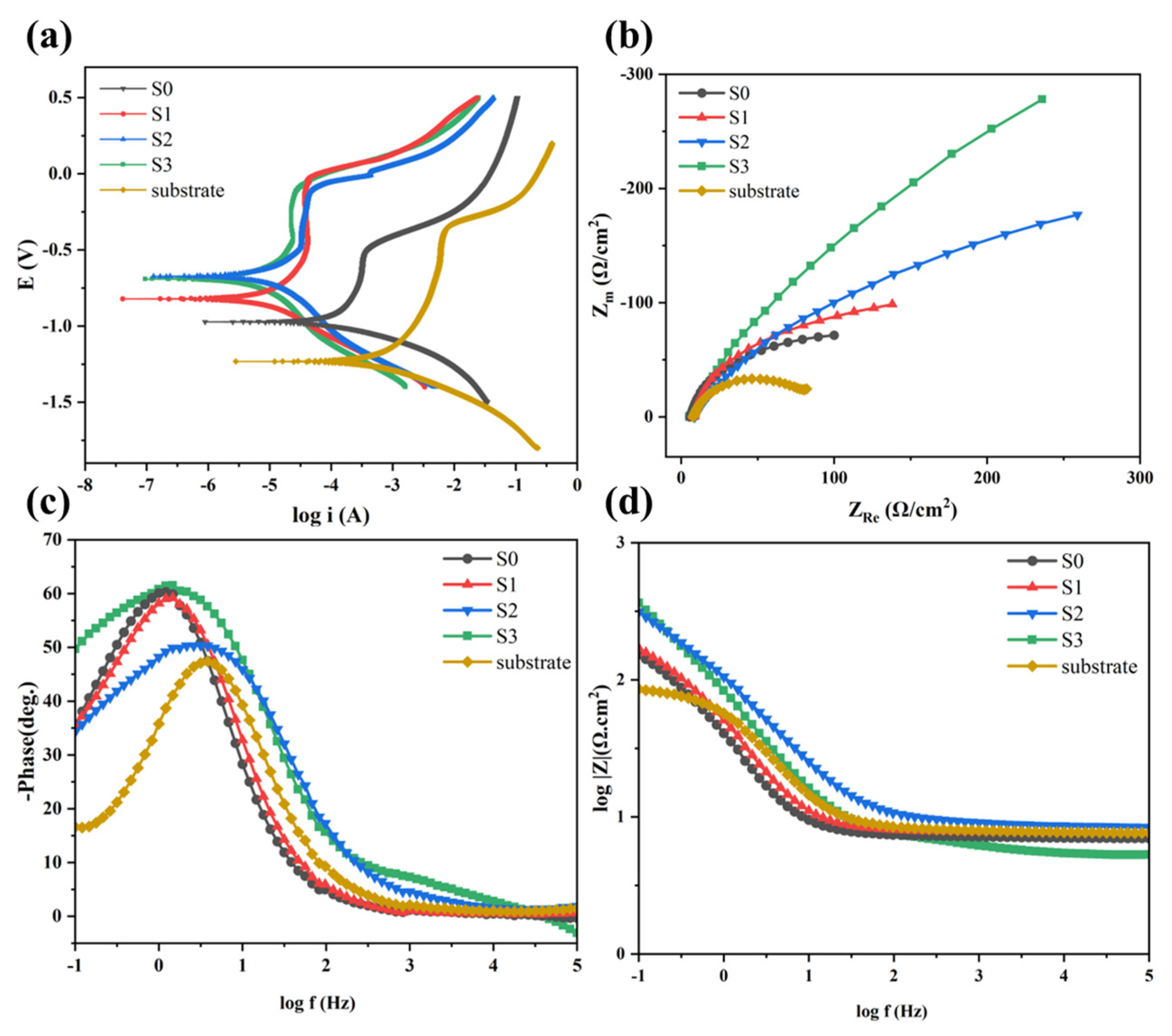
| Preheating Temperature | Icorr/(μA·cm−2) | Ecorr/(V) |
|---|---|---|
| Substrate | 2.05 × 10⁻⁴ | −1.216 |
| Room temperature | 7.45 × 10⁻⁵ | −0.981 |
| 100 °C | 3.56 × 10⁻⁶ | −0.827 |
| 200 °C | 3.36 × 10⁻⁶ | −0.682 |
| 300 °C | 1.53 × 10⁻⁶ | −0.696 |
Disclaimer/Publisher’s Note: The statements, opinions and data contained in all publications are solely those of the individual author(s) and contributor(s) and not of MDPI and/or the editor(s). MDPI and/or the editor(s) disclaim responsibility for any injury to people or property resulting from any ideas, methods, instructions or products referred to in the content. |
© 2024 by the authors. Licensee MDPI, Basel, Switzerland. This article is an open access article distributed under the terms and conditions of the Creative Commons Attribution (CC BY) license (https://creativecommons.org/licenses/by/4.0/).
Share and Cite
Shi, W.; Cheng, C.; Zhang, B.; An, F.; Li, K.; Xiong, Z.; Xie, Y.; He, K. Effect of Substrate Preheating Temperature on the Microstructure and Properties of Laser Cladding Fe/TiC Composite Coating. Lubricants 2024, 12, 216. https://doi.org/10.3390/lubricants12060216
Shi W, Cheng C, Zhang B, An F, Li K, Xiong Z, Xie Y, He K. Effect of Substrate Preheating Temperature on the Microstructure and Properties of Laser Cladding Fe/TiC Composite Coating. Lubricants. 2024; 12(6):216. https://doi.org/10.3390/lubricants12060216
Chicago/Turabian StyleShi, Wenqing, Cai Cheng, Bingqing Zhang, Fenju An, Kaiyue Li, Zhaoting Xiong, Yuping Xie, and Kuanfang He. 2024. "Effect of Substrate Preheating Temperature on the Microstructure and Properties of Laser Cladding Fe/TiC Composite Coating" Lubricants 12, no. 6: 216. https://doi.org/10.3390/lubricants12060216