Article

Microstructural, Mechanical and Tribological Behaviors of Cu/LLDPE-Based Composite Coatings for Lightweight Applications

1
Laboratory of Electromechanical Systems, National School of Engineers of Sfax, University of Sfax, Sfax 3038, Tunisia
2
Department of Mechanical Engineering, Centre for Mechanical Technology and Automation (TEMA), University of Aveiro, 3810-193 Aveiro, Portugal
3
LASI—Intelligent Systems Associate Laboratory, 4800-058 Guimarães, Portugal
4
Department of Research and Development, Rodi Industries, S.A., Eixo, 3801-551 Aveiro, Portugal
*
Authors to whom correspondence should be addressed.
Lubricants 2024, 12(7), 231; https://doi.org/10.3390/lubricants12070231
Submission received: 21 May 2024 / Revised: 12 June 2024 / Accepted: 19 June 2024 / Published: 21 June 2024

Abstract

:
This research work focuses on the development and analysis of copper-filled linear low-density polyethylene (LLDPE) coatings deposited on LLDPE substrate via a thermocompression process. A dry mechanical mixing technique is employed to mix the copper–LLDPE powders. This relevant technology aims to develop new solid lubricating layered composite coatings without a negative environmental impact. Four different materials of the coatings are considered, i.e., LLDPE + 2 wt.% Cu, LLDPE + 6 wt.% Cu, LLDPE + 10 wt.% Cu and LLDPE + 20 wt.% Cu. The microstructural characterizations indicate a good degree of dispersion and adhesion between the continuous and dispersed phases at 20 wt.% Cu coatings. The mechanical properties of the pure polymer and the fully filled composite materials are investigated experimentally using tensile tests and Micro-Vickers hardness. The stiffness, hardness and mechanical strength of the composites are enhanced. Friction tests are also carried out via a linear reciprocating sliding tribometer. The incorporation of copper powder has a significant improvement on the friction and wear properties of the developed coatings. Higher copper powder loading provides a lower friction coefficient and wear volume loss. The best tribological performances are obtained with the LLDPE + 20 wt.% Cu coating. The wear mechanism of the LLDPE substrate is severe adhesive wear, and it becomes mild abrasive wear in case of the 20 wt.% Cu coating.

1. Introduction

It is known that composites are heterogeneous materials that incorporate at least two solidified constituents mixed at a distinctly obvious level without being solvable in each another. The reinforcement material is embedded in the matrix, and it could exist as flakes or particles or fibers. The poor mechanical properties and the low wear performances of polymers restrain their application in different fields of industry. The introduction of a second phase to produce novel hybrid materials and composites may improve the different properties [1].
Commonly, most tribological applications use liquid and grease lubricants to decrease friction and wear properties. In recent years, modern lubrication concepts, including the choice of solid lubricants, have been introduced in severe service conditions (such as extreme contact pressure, vacuum, radiation, very low or high temperatures) and/or to respect some environmental considerations. Solid lubricants have been increasingly used as reinforcement materials in massive products or coatings.
Antifriction thermoplastic-based composites can be designed using different methods, in particular: (a) by hardening a self-lubricating polymer matrix (such as UHMWPE, polyamide, PTFE) with fibers or particles aimed at enhancing its mechanical properties and establishing a coefficient of friction at a same level of neat material [2,3,4,5]; (b) by incorporating solid-lubricant filler (PTFE, MoS2, graphite, etc.) into a high-strength polymer matrix (PEEK, PPS, PI, etc.), ensuring the formation of a high-wear-resistance transfer film on the counterpart, which preserves the strain-hardened properties of the neat polymer [6,7,8,9,10,11,12,13,14,15,16]. Among the various non-metallic and metallic solid lubricant fillers applied in thermoplastic composites, previous works have discussed the positive effects of incorporating a mass content of carbon-based materials not exceeding 10 wt.% to Polyamide 66 (PA66) or ultrahigh-molecular-weight polyethylene (UHMWPE) matrixes on the tribological properties of the composites [6,8]. The introduction of bimetallic fillers such as FeCo [9], quasicristalline alloy powders such as Al-Cu-Fe [10] or tribaloy alloy additives [14] into different thermoplastic polymers enhanced their wear resistance. PTFE polymer, while showing good self-lubricating ability, suffers from poor wear resistance. Therefore, PTFE-based composites filled with MoS2 or glass and/or 40 wt.% bronze powders [7,11] and PTFE–yttria-stabilized zirconia (YSZ) coatings with 20 and 25 wt.% YSZ [13] were developed with the goal of reducing wear damage.
Particularly, metallic particles included as fillers in an organic matrix have been widely used to enhance the thermal, electrical, and mechanical properties of polymers [2,3,17,18,19,20]. It has been reported that the tensile and impact characteristics of high-density polyethylene (HDPE) were increased up to 100% due to the reinforcement with metallic fibers [17]. The incorporation of small grains of metallic aluminum (Al) to a poly(ethylene oxide) matrix showed maximum conductivity for the composites with a much smaller amount of Al filler added [18]. The thermal conductivity and mechanical properties of composites containing metal Ni powder in their matrix from epoxy resin were improved due to the increase in the specific area of the Ni powder [19]. The electrical stability of different polymer/Ni filler composites was enhanced due to the crosslinking structure of the materials [20]. It was demonstrated in [21] that the incorporation of copper oxide particles as metal oxide compounds to epoxy resin matrix with particle sizes in the range of 40–60 nm enabled and increase in the strength and plastic properties compared to composites reinforced with a 10–30 nm particle size.
In the literature, little is discussed on the effects of metallic particles such as copper and copper alloys on the tribological behavior of organic matrixes [22,23,24,25,26,27,28]. Due to their low friction coefficient and excellent anti-wear abilities, copper and copper alloy powders have been added as a lubricating phase in an organic material and formed a typical micro-composite structure (organic matrix/metal powder) that not only enhanced the hardness and the mechanical properties but also provided a solid lubricating effect. Rajesh studied the influence of incorporating 6 wt.% metallic powdery fillers such as copper and bronze into 20 wt.% glass fiber (GF)-reinforced PA11 composites on the tribological and mechanical properties of the fabrics [22]. It was found that the two metallic powders further improved the friction and wear properties of the composites. A more beneficial effect was observed for copper powder in this context. The inclusion of 6 wt.% Cu or 6 wt.% bronze in PA11+GF also showed an improvement in the tensile strength, flexural strength and hardness shore B, with a further increase with the copper powder addition. The result was attributed to the better compatibility between the Cu powder and the PA 11 matrix compared to the bronze powder.
Tsetlin et al. investigated the mechanical and tribological properties of an ethylene–tetrafluoroethylene copolymer matrix filled with micro-sized Al−Cu−Fe quasicrystalline powder in the range of 1, 2, 4 and 8 vol% concentrations [24]. Even if there was no improvement in terms of the mechanical properties, it was found that the friction coefficient had been decreased twice at 1 vol% of the metallic powder, and the wear resistance had also been improved by 40 times at 8 vol%. Charfi et al. studied the tribological behavior of PTFE + 30 wt.% Bronze composite was used in the guide rings of hydraulic cylinders [25]. The authors noted that the frictional behavior of the composites was satisfying for low values of load and frequency. Other works have investigated the friction and wear properties of Acrylonitrile Butadiene Styrene reinforced with copper powder using a pin-on-disc tribometer under different loads and sliding velocities [26]. Composites with 2.5 wt.% and 5 wt.% of copper were developed via fused deposition modelling. The different results showed that the friction coefficient and the wear loss decreased with the increase in the copper content. Recently, it was reported by Akrout et al. that the incorporation of 5 wt.%, 10 wt.% and 15 wt.% Cu micro-powder to an ABS matrix simultaneously improved the tribological and the micro-mechanical characteristics of the composites [27]. Interestingly, the friction coefficient decreased with the increase in the copper content, while the elastic modulus, the Vickers hardness and the indentation hardness increased. The same results were found when studying the PA/Cu micro-composite properties [28]. An enhanced hardness and stiffness were highlighted by indentation tests. The tribological findings point to copper’s efficiency in reducing friction and wear properties. It was reported in [29] that the addition of nano sized Al65Cu22Fe13 quasicrystals to linear low-density polyethylene (LLDPE) improved the elastic modulus and the tensile strength of the material as well as its friction and anti-wear properties.
These studies provide a strong foundation and background to work on this subject in a more comprehensive and practical way. This experiment is a new initiative to develop a hard coating deposited on an organic substrate to create a self-lubricating surface with increased mechanical properties. What is innovative about our research work is to develop thermoplastic composite coatings with multi-functionalities and superior protective properties using an environmentally friendly process. The composite coatings combine the lightweight properties of polymers, anti-corrosion properties, low cost and facilities of processing, as well as the strengthening properties and solid-lubricating effects of the metallic particles incorporated. These innovative materials can be categorized into advanced coatings for a green revolution due to their lightweight properties, fuel efficiency in the transport sector and less pollution due to the use of environmentally friendly composites as molding materials. In this paper, coatings of LLDPE/copper composites were prepared on LLDPE substrate using the thermocompression molding technique.
Therefore, the object of this paper strives to develop solid lubricating composite coatings via an environmentally friendly process for bearing applications and to discuss the effects of filler content on the mechanical and tribological properties of the new materials. In this experiment, most of the techniques employed are quantitative; qualitative observations of the wear scars after friction tests enables a better understanding of the wear mechanisms. It is hoped that the results reported in the experimental work will help us to better explore the innovative materials in the design and manufacturing of machine systems in which no external grease or oil lubrication is acceptable. The composites in the study are particularly suitable to produce parts in sliding contact such as in linear motion guides, mechanical seals, and internal guide pins in pneumatic cylinders on which the surfaces are subjected to linear reciprocating friction against steel counterparts [7].

2. Experimental Details

2.1. Materials

The basic materials investigated in this work consisted of copper powder incorporated into LLDPE as a matrix material to form coatings prepared on LLDPE substrate. The polymer matrix in the powder was provided by KIMPAS of Turkish with a 300 µm average particle size, 135 °C melting temperature and 0.938 g/cm3 density. The filler material was copper, with a 75 µm average size, 8.94 g/cm3 density and 98% purity. The powder was purchased from Sigma Aldrich Chemistry (St. Louis, MO, USA). Different compositions of the coatings were considered in the range of 2, 6, 10 and 20 wt.% copper. All the experimental results of the coatings were compared to those obtained using the LLDPE substrate.

2.2. Sample Preparation

As shown in the schematic representation of the experimental procedure in Figure 1, a dry particle mechanical mixing process was performed to mix the two solid phases together. For this purpose, a magnetic stirrer was used. The stir bar, placed at the bottom of the tank, employs a rotating magnetic field to spin very quickly and mix a quantity of ten grams of LLDPE powder and copper powder. Thus, the two constituents were mechanically mixed in the selected weight proportion at room temperature. The rotating velocity was 200 rpm, and the mixing time was 10 min. The powder mixtures were used to prepare fully filled composite materials, which were cut out by using a press to prepare the tensile samples as well as composite coatings to characterize hardness and morphological and tribological aspects. For that, one gram of powder mixture was carefully spread in the bottom of cylindrical stainless-steel mold, and a cylindrical piston was placed over the powder mixture with rotational movement to ensure a constant thickness of the film. A quantity of 10 g of pure LLDPE was spread over the powder mixture. Thereafter, the stainless-steel piston was placed again above the LLDPE substrate to maintain the molding pressure stable. For a time of 10 min, the mold was subjected to thermo-compression molding using a hot press set at a pressure of 50 bars and a temperature of 160 °C. The mold was then cooled using water circulation.
A demolding mechanism has been conceived with the mold based on screw–nut system pressing on the piston to extract the sample (Figure 1). Cylindrical specimens were recovered from the mold with an approximatively 5 mm height and about 0.5 mm coating thickness. Fully filled composite plates with a thickness of three millimeters made from the different mixtures were also compression-molded to prepare the tensile samples. Figure 2 shows examples of specimens produced for the tensile tests and an example of the LLDPE/Cu coating used for the microhardness and tribological tests. The variations in the surface roughness Ra of the substrate and the coatings as a function of the copper content are given in Table 1.

2.3. Mechanical and Microstructural Characterizations

Uniaxial tensile tests were conducted using a WDW-5D universal machine (Chengyu, Shandong, Chine) under test conditions according to ISO 527-2 [30] at a crosshead speed of 10 mm/min. Composite samples with different weight fractions of copper were prepared via thermal molding of film that was 3 mm thick using the same experimental protocol described in Section 2.2. The films were cut out using a hand press in a dumbbell shape according to ASTM standards (D638-MIII) [31]. The results were averaged for at least 3 samples. The mechanical properties included a measurement of the tensile modulus E, MPa, yield stress σy, MPa and the failure strain εf (%).
Micro hardness measures were performed using a Micro Vickers hardness tester (Falcon 400-Innovatest, Paris, France). A diamond pyramid indenter with a face angle of 136° was used. In these tests, composite coatings were used by applying the conditions of a 100 gf test force for a 10 s dwelling time [32]. The mean value among three different points was set as the final value of the micro hardness.
The microstructure of representative coatings was analyzed using optical microscopy (LEICA DM 2700M, Wetzlar, Germany) and scanning electron microscopy (SEM) (Hitachi TM400Plus, Toronto, ON, Canada) with energy dispersive X-ray spectroscopy (EDS). Freeze fractures were carried out in cross sections of the coatings, and the different features were imaged using SEM.

2.4. Friction and Wear Testing

The tribological investigations of the LLDPE substrate and LLDPE/copper composite coatings were conducted using a reciprocating ball on a flat tribometer. The used device was described in a previous published work [8]. A high-chromium steel ball (100Cr6) with a diameter of 10 mm and a surface roughness of Ra = 0.12 µm was used as a counterpart. The cylindrical coated specimens were cut into rectangular samples with dimensions of 20 × 25 × 5 mm3. The friction tests were carried out under a constant normal load of 7.62 N, a tangential cyclic motion of ±7.5 mm and a 1 Hz frequency. The duration of the friction tests was fixed to 10,000 cycles. For each composition of the coatings, at least three sliding tests were conducted. At the end of each test, the wear scar was cleaned with alcohol to eliminate wear debris. The cross-section S (mm2) and the transversal profiles were determined in each wear scar using a Surtronic® S-100 Surface Roughness Tester (AMETEK Taylor Hobson, Leicester, UK). For each sample, three measurements of the wear track cross-section were taken at both ends of the track and at the center of the track, and the average value was considered in calculating the wear volume. The volume loss V (mm3) was established as follows:
V = S × d
where d is the length of the sliding stroke which is equal to 15 mm.
The wear tracks were characterized qualitatively using an optical microscope to analyze the wear mechanisms. Also, SEM and/or EDS analysis were undertaken on the top surfaces of the coating wear scar as well as the corresponding steel counterpart (SEM-Quanta 250, FEI, Hillsboro, OR, USA).

3. Results and Discussion

3.1. Morphological and Mechanical Properties

Figure 3a shows a SEM image of the superficial surface of the 20 wt.% Cu coating after polishing using SiC papers with grit sizes ranging from 120 grit to 1200 grit. The bright regions correspond to the Cu filler, while the darkest regions correspond to the continuous thermoplastic matrix. The dispersion of copper through the LLDPE polymer is relatively uniform, even at high contents. EDS taken using the Thermo Scientific’s Pathfinder-SEM/NSS software tool shows Cu and carbon dot mapping at the same coating conditions (Figure 3b). The image confirms the good degree of dispersion of the Cu powder throughout the matrix, with the presence of some clusters. The last result was explained by the location of the filler in the amorphous regions of the semi-crystalline polymer [33]. According to the figures, there were no signs of large copper aggregation at maximum filler loading.
Figure 4 shows SEM images of the Cu powder and the cross section of the LLDPE + 20 wt.% Cu coating after freeze fracturing. The Cu powder exhibited an irregular shape, with small flakes adhering the largest particles (Figure 4a). A rough topography in the LLDPE composite coating was created from the freeze fracture (Figure 4b,c). The coating was almost uniform in depth, with good dispersion of the filler. SEM investigations also disclosed that the interface between the LLDPE substrate and the LLDPE + 20 wt.% Cu coating was continuous and perfectly adhering to the substrate due to the organic phase forming both substrate and coating. In another part, Figure 4d,e show a good interfacial adhesion between the filler and the matrix in two different regions despite the irregular size and shape of the Cu powder. The micro-cavitation phenomenon due to particle detachment was limited, and few signs of micro-debonding were seen due to the freeze fracture. The polymer had some degree of compatibility with Cu powder, since no large voids appeared between the dispersed and continuous phases.
Figure 5 presents typical stress–strain curves plotted according to the tensile test results of the LLDPE and of the LLDPE/Cu composite materials with different contents of the metallic filler. All the curves showed a linear range corresponding to the elastic region. The yield point occurred in a distinct maximum of the elastic region and just before the transition to permanent deformation, after which the onset of necking was produced, causing a gradual increase in the stress values as a function of load until breakage. It is clearly seen from the figure that the incorporation of Cu powder decreased the tendency of the polymer to draw and affected its mechanical strength.
The effects of Cu on the yield stress, modulus of elasticity, and failure strain are given in Figure 6. As shown in Figure 6a, the Cu particles improved the yield strength and modulus of the LLDPE. The average value of Young’s modulus of pure LLDPE was about 416 MPa, which was in the same order of magnitude found in the research of Nguyen et al. [34]. The Young’s modulus of the composites had higher values than the neat polymer. The maximum value was obtained for 20 wt.% copper, and it was about 855 MPa. The metallic filler was much stiffer than the thermoplastic matrix; thus, the stiffness of the composites was enhanced with the increase of copper loading, and an increase in crystallinity established by the incorporation of metallic filler is possible [3,32]. Similarly, the yield stress of the composites slightly increased from the value of pure LLDPE. The average value was improved from 18.5 MPa for pure LLDPE to 24.8 MPa in the case of 20 wt.% Cu composite coatings. It is believed that the properties are affected by the reinforcing effect of the metallic fillers [33]. Uflyand et al. reported that quasi-crystalline nano filler of Al65Cu22Fe15 was organized in the amorphous regions of the LLDPE matrix, which improved the modulus and the strength of the composites [29]. Similar findings were noticed by Luyt et al. [33]. Additional crystallization can occur when copper micro-particles locate themselves in the amorphous regions and in the interlamellar spaces of LLDPE polymer.
Figure 6b shows a brittle failure and much lower elongation of the Cu-filled LLDPE. The average value dropped from 529% to 179.8% when the copper mass ratio increased from 0 wt.% to 10 wt.%. This tendency is consistent with the literature data implying that the weakness at the interface between the filler particles and the matrix and the lack of chemical bonding is a major factor affecting the ductility of the composites. Similar findings were reported elsewhere [29,33,34]. Furthermore, according to a previous study reported by Nickzad et al. [35], the morphology of oxides on the metal surface and its environmental stability can be responsible for the development of long-term durability polymer–metal bonds.
Figure 7 shows the Vickers microhardness for the LLDPE/Cu coatings. The major contribution of these histograms is the confirmation of the yield stress evolution tendency, since these two mechanical parameters are believed to be related. From the figure, we can observe a minimum value of micro-hardness with the substrate from pure LLDPE followed by a continuous increase. It is worth remembering that there is an exponential relationship between the material moved during micro-scratch testing and its Vickers micro-hardness: the area of the displaced material (groove and two top ridges) is lower when the hardness is higher [36]. This last result will be further discussed in the subsequent section.

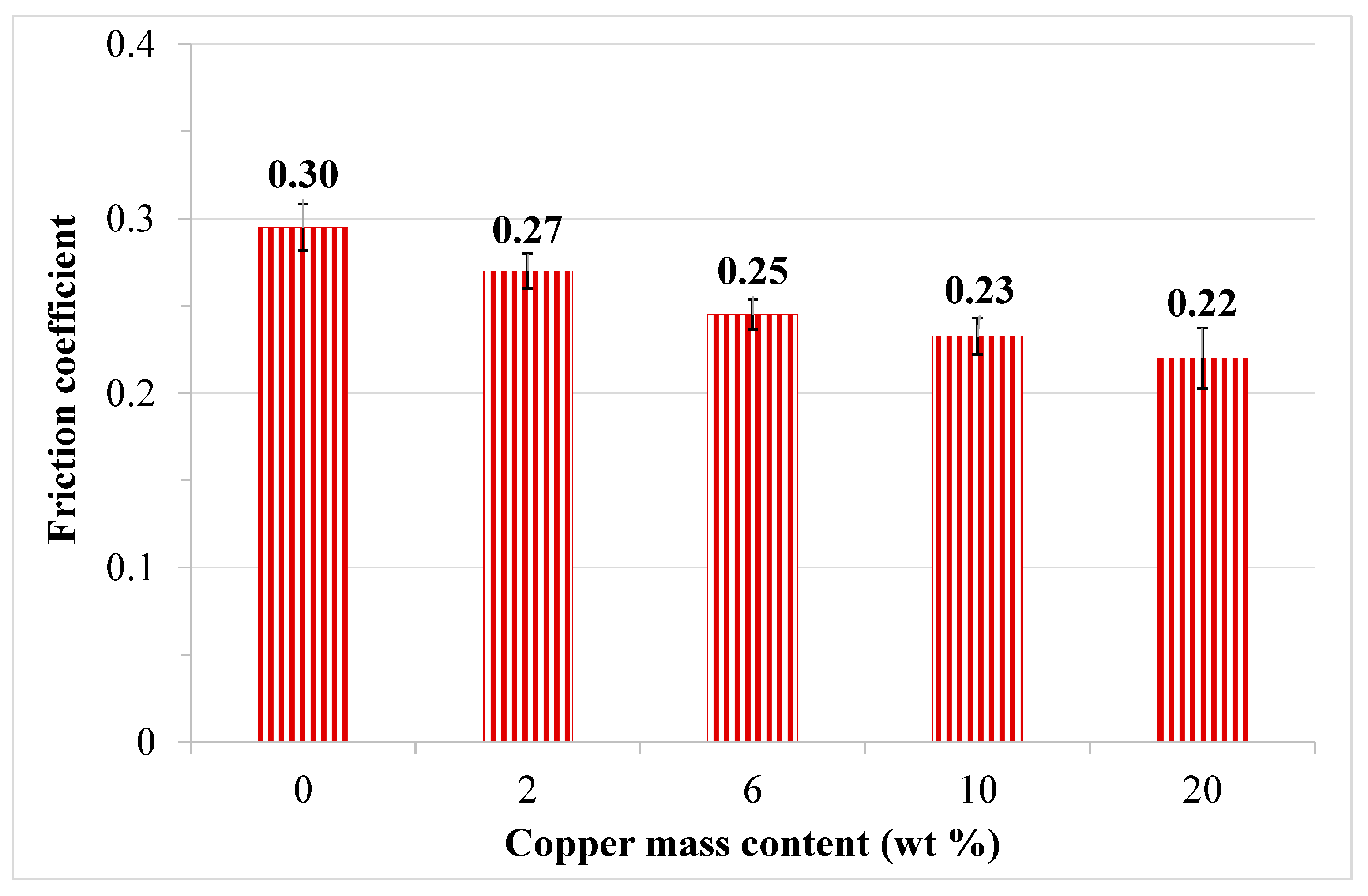
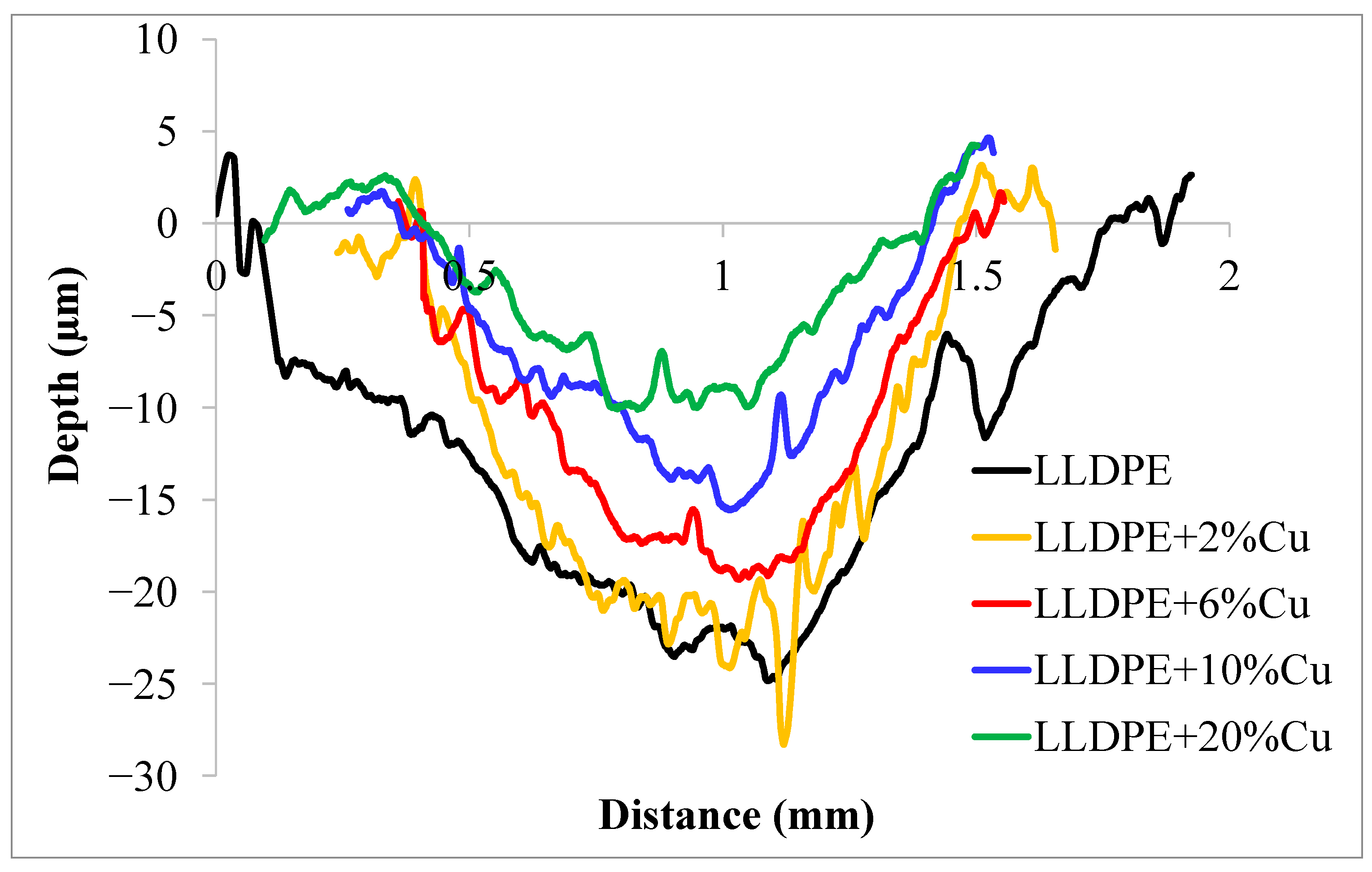
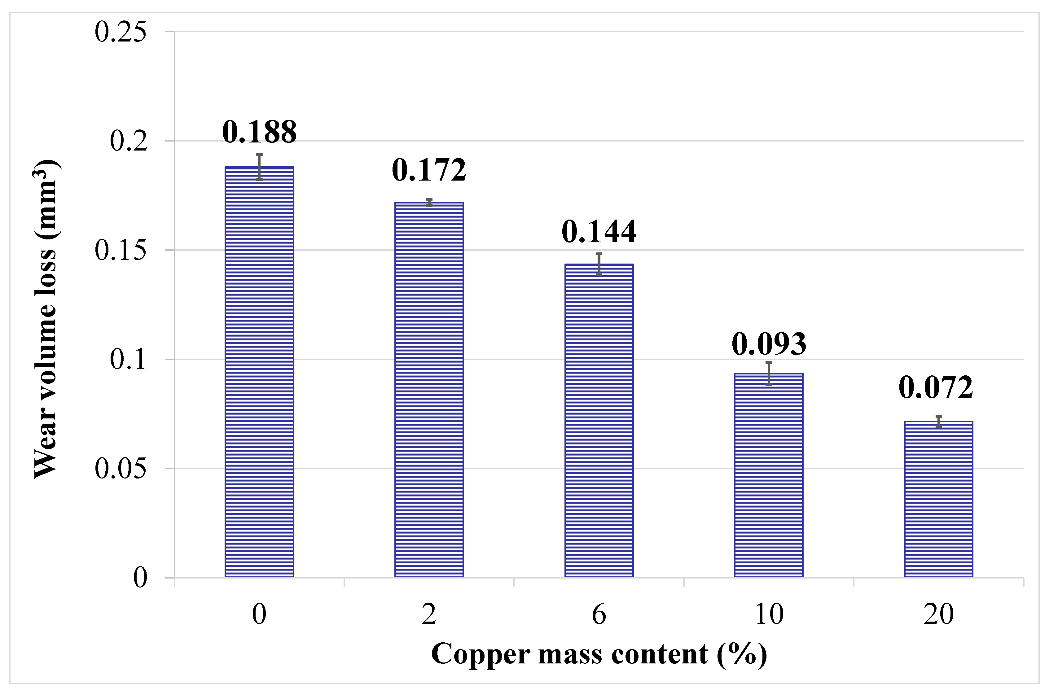
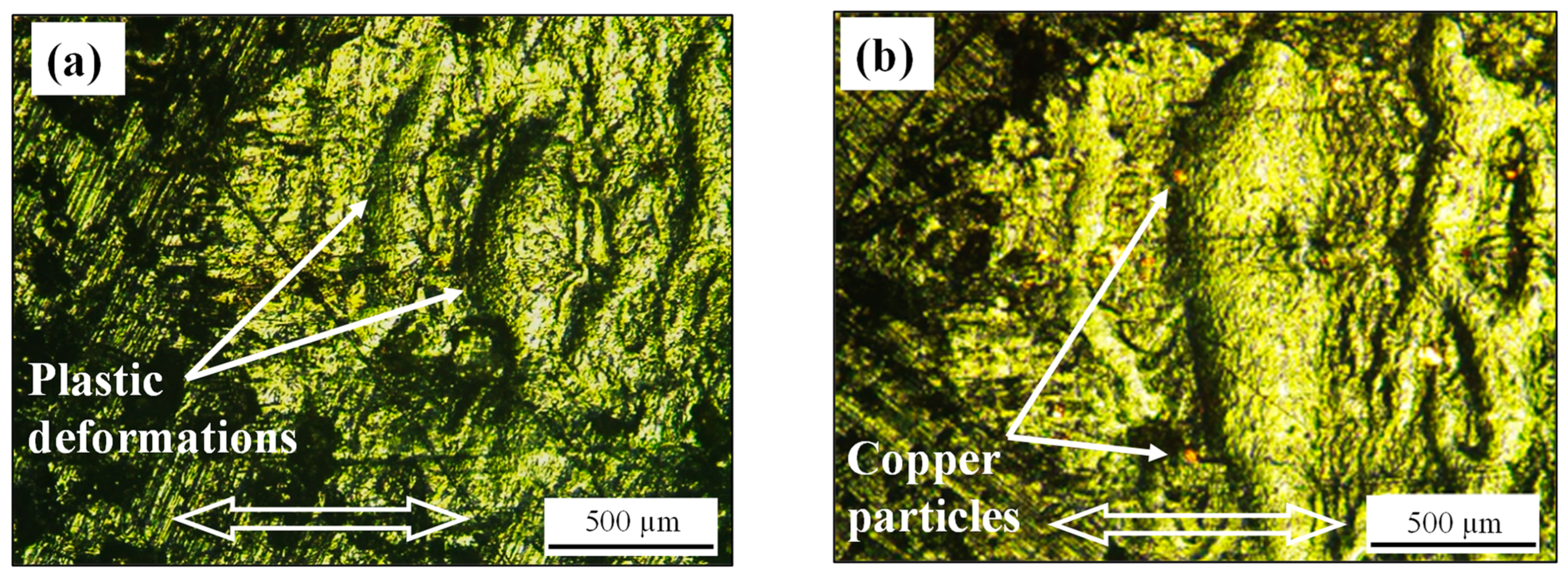
3.2. Friction and Wear Behaviors

Typical examples of the coefficient of friction per sliding cycles for the considered LLDPE/Cu coatings and for the LLDPE substrate are plotted in Figure 8. A run-in stage is observed over the 50 first cycles, where the two bodies’ surfaces evolved an accommodation in the sliding process. In an intermediate stage, the friction coefficient increased slightly until reaching a stable value for the steady-state stage. This second stage can be attributed to the generation of a bed of a third body (detached particles) separating the two first bodies (composite coating/steel ball) as well as the formation of a transfer film on the surface of the antagonist [24]. The steady-state friction follows the second stage during which the coefficient of friction remains almost constant as a function of the sliding cycles. A stable interaction between the third body trapped in the contact surface and the transfer film formed on the antagonist was established. The LLDPE + 20 wt.% Cu coating had the most stable friction curve. The differences in the steady state stage are attributable to the composition of the coatings and their surface properties. It was established that the incorporation of a hard phase randomly dispersed in a soft polymer matrix can effectively decrease the true contact area against the counterface, hence lowering the adhesion forces between the relative sliding bodies in contact [37]. This is not surprising, since higher values of elastic modulus and hardness are established as a result of the variations in coating compositions.
Figure 9 illustrates the variations in the mean friction coefficient measured after 10,000 cycles for the LLDPE substrate and the LLDPE/Cu coatings. The friction coefficient values experienced a smooth decrease as a function of the increase in Cu content. Interestingly, the coating with 20 wt.% of copper gave the lowest coefficient of friction; the mean value was reduced from 0.29 for the LLDPE substrate to 0.22. Hence, a positive effect was obtained for the friction results, with a more significant impact at the maximum filler content. Brostow et al. [15] have reported that a reduction in the real contact area can occur as more filler particles are located in the contact surface; thus, fewer polymer asperities would be deformed.
Figure 10 displays examples of typical cross-section profiles recorded at the central part of the wear track for the LLDPE substrate and the different LLDPE/Cu coatings. Changes in the micro-geometry of the wear profile grooves are clearly seen from the figure. A deep and large wear groove is exhibited for the substrate, while adding 2 wt.% of copper to the coating enhances the wear resistance by reducing the width of the wear groove. A decrease in the depth at the center of the wear mark is observed in the coating profiles. Interestingly, the coating with 20 wt.% Cu gave a smooth and narrow profile, and the wear picks were relatively stumped.
Figure 11 shows the variations in the wear volume loss with respect to the different weight percentages of Cu filler. This was determined based on the measurement of the surface area of the wear groove in three different samples. The virgin LLDPE substrate exhibited a higher wear volume loss, and a decreasing trend in wear was observed when increasing the filler content in the coatings. An average volume loss of 0.188 mm3 was obtained for the LLDPE substrate; this became equal to 0.071 mm3 with 20 wt.% Cu. One may expect that a higher wear resistance takes place with the incorporation of higher weight fractions of metallic powder in the thin coatings [38]. The formation of a continuous and thin transfer layer on the surface of the counterpart enhances the wear resistance [38]. This phenomenon will be further discussed in the following paragraphs.
Optical observations in the imprint zone of the friction tests for the substrate and the 2 wt.% Cu coating (Figure 12) are characterized by severe plastic deformations and scuffing. Wear debris is dispersed in the form of flakes. The abundant wear particles are more likely to enter inside the gaps between the asperities of the friction pair (steel ball-LLDPE) and then become pressed together under the applied normal load. A rough surface with micro-cracks is also observed due to the surface fatigue under long-term frictional interactions. The low content of Cu in the coatings gives the same wear mechanisms as the LLDPE substrate. This is strong evidence that a detachment–bonding process and the patches of softened surfaces characterize the wear mechanisms of both materials. It is believed that a strong melting of LLDPE occurs as a result of friction [29]. A predominant adhesive wear mode is experienced.
Changes in the wear mechanisms of the LLDPE + 10 wt.% Cu and LLDPE + 20 wt.% Cu coatings are depicted in Figure 13. The extent of the plastic deformation phenomenon has been reduced in the case of the LLDPE + 10 wt.% Cu composite coatings. The deformation is associated with some delamination, micro-cracks and pitting. Light scratches are also observed. Such transformations in the topographical features counted for the wear reduction process. The generated wear mechanism is a mild adhesive-abrasive mode. An optical examination of the 20 wt.% Cu coating after the friction test showed light scratch marks and grooves parallel to the sliding direction (Figure 13b). The filler particles were clearly observed and protruded out of the matrix surface. Ploughing furrows were mainly formed over the hard contact surface by the subsequent plastic deformation over the same surface or by the embedded abrasive particles. The edge part of the wear scar showed some filler particles removed from the LLDPE matrix surface and ejected from the wear area. Copper particles separated from the matrix at the sliding contact interface, resulting in the presence of the three-body abrasion. Evidently, this would give rise to the wear resistance because the metal filler has much better hardness and mechanical properties compared to matrix material. Such features have been reported by many authors in their selected materials [24,39,40], which was thought to be due to the particles detaching in the sliding trace coupled with the decrease in the polymer surface melting. On the following, wear mechanisms will be also identified and mapped using SEM with energy dispersive X-ray spectroscopy (EDS). The tribological behavior of the composites and the changes in the wear mechanisms with and without filler incorporation will be better understood and clearly depicted.
Figure 14a–c show the typical plastic deformation and micro-ploughing wear mode as a principal material removal mechanism of the LLDPE substrate. LLDPE elongates until it splits up from its surface in the shape of thick lump (Figure 14c). The steel counterpart in Figure 14d,e shows transferred polymer as flake-like particles of micrometric size. At higher magnifications, Figure 14e shows polymer transfer to the central part of the contact as non-coherent thick film. The transfer film is steadily carried away from counterpart surface, which increases the wear volume loss [41]. SEM evidences the severe adhesive wear mode of the LLDPE polymer.
Figure 15 shows the SEM micrographs of the worn surface of the LLDPE + 20 wt.% Cu coating (Figure 15a) and EDS spectra on two specific regions of the sample. The worn surface of the coating can be divided into areas with visible copper particles and polymer areas. It is clearly seen that the wear on the metallic reinforcement is smoother and shows less plucked and ploughed signs than the polymer area. The wear mechanisms on the polymer areas are almost similar except for those due to plastic furrow deformation and hard particle erosion. Figure 15 also shows material flow caused by progressive plastic deformation along the sliding direction through the contacting surface. The compressive stress, tensile stress and friction heat originate and expand the polymer flow. High stresses and temperatures are produced at these local regions of intensive contact and then generate polymer flow and mechanical and chemical bonding, and these in turn smoothen the transfer film [42].
The results of the EDS elemental analysis show the existence of Cu and O in the composite surface and inside the wear scar. It is also observed from Figure 15b,c that the O element and Cu element contents inside the wear track are greater than those of the unworn surface of the composite. The above EDS results reveal that, during the sliding process, the oxidation of Cu was the dominant chemical process responsible for surface hardening. The film of detached particles on the worn surface contained copper debris (with oxides included) and LLDPE debris. This indicates a strong tendency to furrowing and abrasive wear due to the abrasive nature of the copper wear particles peeled off from the coating. The Cu debris serves as conductive particles and abrasive particles with a high performance in heat conduction [42].
The worn surface morphology of the LLDPE + 20 wt.% Cu steel counterpart is illustrated in Figure 16a–c, revealing the formation of thin and coherent transfer film covering the surface of the contact. The transfer film contributed to the wear process in place of hard steel asperities. It was experimentally established in [36] that ultra-wear-resistant polymer/metal composites were formed due to the hardening of their surface layers upon friction. Tribosynthesis and tribodestruction are the two transformations involved in the tribochemical processes, leading to an increase in adhesion between the filler and the polymer, especially with the production of local temperature flares upon protrusions of the counterbody with the collisions of the solid filler particles. This phenomenon led to an increase in nucleation and the formation of transfer film on the surface of the antagonist, enhancing the wear resistance during sliding.
The thin and uniform transfer film formed on the steel counterpart was firmly adherent onto the counterpart and hardly scaled off during sliding. It can also be seen in the SEM micrographs of Figure 16 that the LLDPE composite debris formed island-like lumps and was accumulated around the contact surface. A secondary transfer film containing a significant proportion of LLDPE polymer and metal filler may be formed on the surface of the antagonist due to material transfer from the polymer with a lower cohesive energy density to the antagonist having a higher cohesive energy density [43].
The EDS analysis revealed the elemental composition of the surface of the antagonist. Table 2 shows the presence of Cu, C and O elements in the area covered by the transfer film. This result might suggest that the consistency and the coverage of the transfer film formed on the LLDPE + 20 wt.% Cu counterpart were better than those obtained in the transfer film of the neat LLDPE sample. Cu particles were also transferred from the composite surface and embedded in the transfer film. As observed by Rajesh and Bijwe during wear studies of PA11/Cu composites [22], the Cu filler can chemically react with the steel antagonist and forms an intermetallic compound, which may improve the adhesion between the metallic counterpart and the transfer film. Hence, a positive effect in the friction results was obtained, with a more significant impact at a maximum filler content. The copper filler was effective in interrupting the large-scale fragmentation of the transferred polymer, which improved the adhesion of the transfer film and also had a high performance in heat conduction.

4. Conclusions

The morphological, mechanical and tribological results of LLDPE/Cu composite coatings developed on a flat LLDPE substrate are presented. SEM characterizations showed good degree of filler dispersion and adhesion at high concentrations. The mechanical properties, including the elastic modulus, yield strength and Vickers microhardness, increased with increases in the copper content. It was reported that the coatings’ stiffness and hardness depended significantly on particle loadings, since the metallic fillers had much larger modulus and hardness values than the polymer matrix [2]. It was also shown that the failure strain decreased with the addition of copper particles into the LLDPE matrix. This is expected, because the composites brittleness/toughness strongly depends on particle loading as well as particle/matrix adhesion.
It follows from the tribological results that there was also a continuous decrease in the friction coefficient and the wear volume loss of LLDPE with increasing copper contents in the coating. The friction coefficient gained the minimum value of 0.22 when the copper ratio was 20 wt.%. In that case, the wear volume loss decreased by more than two times when compared to the pure polymer. The wear mechanisms of the LLDPE substrate were severe adhesion and serious plastic deformations. A three-body abrasion in a mild wear process was the principal wear mechanism characterizing the LLDPE + 20 wt.% Cu composite coating. An investigation of the contact surface on the counterpart indicated a modification in the morphology of the transfer film due to the presence of Cu debris in the film of detached particles. The EDS analysis revealed an identifiable increase in the copper area inside the wear track as well as its presence in the transfer film. It also showed that oxidation of Cu was the principal chemical process that occurred between the two solid surfaces in contact. A strongly bonded transfer film was formed on the surface of the steel ball sliding against the LLDPE + 20 wt.% Cu composite coating. Copper filler enhanced the adhesion of the film and was also efficient in heat conduction during sliding.

Author Contributions

Methodology, C.C.; Validation, A.P.; Resources, A.B. and A.H.; Writing—original draft, B.B.D.; Writing—review & editing, M.K. and M.D.; Supervision, A.P.; Project administration, C.C.; Funding acquisition, A.P. All authors have read and agreed to the published version of the manuscript.

Funding

The authors acknowledge the support by the projects UIDB/00481/2020 and UIDP/00481/2020—Fundação para a Ciência e a Tecnologia. This work was also supported by the PRR—Plano de Recuperação e Resiliência and by the NextGenerationEU funds at Universidade de Aveiro, through the scope of the Agenda for Business Innovation “AM2R-Agenda Mobilizadora para a inovação empresarial do setor das Duas Rodas” (Project no. 15 with the application C644866475-00000012).

Data Availability Statement

The original contributions presented in the study are included in the article, further inquiries can be directed to the corresponding author.

Acknowledgments

Financial support from the Laboratory of Electromechanical Systems in the National School of Engineers of Sfax and the Ministry of Higher Education and Scientific Research of TUNISIA under the PEJC project [20PEJC 06-14] is gratefully acknowledged.

Conflicts of Interest

Author César Cardoso was employed by the company Rodi Industries. The remaining authors declare that the research was conducted in the absence of any commercial or financial relationships that could be construed as a potential conflict of interest.

References

  1. Robinson, D.N.; Binienda, W.K.; Ruggles, M.B. Creep of Polymer Matrix Composites. I: Norton/Bailey Creep Law for Transverse Isotropy. J. Eng. Mech. 2003, 129, 310–317. [Google Scholar] [CrossRef]
  2. Fu, S.-Y.; Feng, X.-Q.; Lauke, B.; Mai, Y.-W. Effects of particle size, particle/matrix interface adhesion and particle loading on mechanical properties of particulate–polymer composites. Compos. B 2008, 39, 933–961. [Google Scholar] [CrossRef]
  3. Gungor, A. Mechanical properties of iron powder filled high density polyethylene composites. Mater. Des. 2007, 28, 1027–1030. [Google Scholar] [CrossRef]
  4. Kim, M.H.; Park, C.I.; Choi, W.M.; Lee, J.W.; Lim, J.G.; Park, O.O. Synthesis and material properties of syndiotactic polystyrene/organophilic clay nanocomposites. J. Appl. Polym. Sci. 2004, 92, 2144–2150. [Google Scholar] [CrossRef]
  5. Hua, Y.; Yang, Y.-C.; Yamanaka, A.; Ni, Q.-Q. Low Friction Coefficient Property of Super Fiber-Reinforced Composites. Adv. Compos. Mater. 2011, 20, 133–147. [Google Scholar] [CrossRef]
  6. Ben Difallah, B.; Cornualt, P.H.; Kharrat, M.; Dammak, M.; Monteil, G. On the Role of Solid Lubricant Fillers in the Tribological, Micromechanical, and Morphological Properties of PA66 Composites. J. Tribol. 2020, 142, 051901. [Google Scholar] [CrossRef]
  7. Trabelsi, M.; Kharrat, M.; Dammak, M. On the Friction and Wear Behaviors of PTFE Based Composites Filled with MoS2 and/or Bronze Particles. Trans. Indian. Inst. Met. 2016, 69, 1119–1128. [Google Scholar] [CrossRef]
  8. Huang, G.; Zhang, T.; Chen, Y.; Yang, F.; Huang, H.; Zhao, Y. Graphite Fluoride as a Novel Solider Lubricant Additive for Ultra-High-Molecular-Weight Polyethylene Composites with Excellent Tribological Properties. Lubricants 2023, 11, 403. [Google Scholar] [CrossRef]
  9. Aydemir, T.; Burlakova, V.E.; Drogan, E.G.; Dzhardimalieva, G.I.; Uflyand, I.E.; Shershneva, I.N.; Kydralieva, K.A. Mechanical and Tribological Properties of Polymer Materials Based on Heterometallic Fe (III) Co (II) Polyacrylamide Complexes. Compos. Mech. Comput. Appl. 2021, 12, 81–92. [Google Scholar] [CrossRef]
  10. Tsetlin, M.B.; Teplov, A.A.; Belousov, S.I.; Chvalun, S.N.; Golovkova, E.A.; Krasheninnikov, S.V.; Golubev, E.K.; Presnyakov, M.Y.; Orekhov, A.S.; Vasiliev, A.L. Effect of a quasicrystalline filler on the tribological properties of a composite based on ultrahigh-molecular-weight polyethylene. J. Synch. Investig. 2015, 9, 1077–1084. [Google Scholar] [CrossRef]
  11. Pasha, B.M.; Budan, D.A.; Basavarajappa, S.; Yadav, S.M.; Nizamuddin, B.A. Studies on wear resistance of PTFE filled with glass and bronze particles based on Taguchi technique Nizamuddin. J. Thermoplasc. Compos. Mater. 2012, 26, 243–259. [Google Scholar] [CrossRef]
  12. Faujdar, E.; Singh, R.K. Amide polymers based on N-phenyl-p-phenylenediamine with α-olefins-co-maleic anhydride as multifunctional additives for lubricant application. Polym. Adv. Technol. 2022, 33, 2820–2834. [Google Scholar] [CrossRef]
  13. Wang, Y.; Zhao, Y.; Darut, G.; Poirier, T.; Stella, J.; Wang, K.; Liao, H.; Planche, M.-P. A novel structured suspension plasma sprayed YSZ-PTFE composite coating with tribological performance improvement. Surf. Coat. Technol. 2019, 358, 108–113. [Google Scholar] [CrossRef]
  14. Khoddamzadeh, A.; Liu, R.; Wu, X. Novel polytetrafluoroethylene (PTFE) composites with newly developed tribaloy alloy additive for sliding bearings. Wear 2009, 266, 646–657. [Google Scholar] [CrossRef]
  15. Brostow, W.; Buchman, A.; Buchman, E.; Olea-Mejia, O. Microhybrids of Metal Powder Incorporated in Polymeric Matrices: Friction, Mechanical Behavior, and Microstructure. Polym. Eng. Sci. 2008, 48, 1977–1980. [Google Scholar] [CrossRef]
  16. Shamsuddin, M.S.M.; Othman, A.H.; Nasir, R.M.; Hassan, A.; Senawi, R.; Thirmizir, M.Z.A.; Ishak, Z.A.M. Influence of PTFE as a solid lubricant on the mechanical, electrical, and tribological properties of CF-reinforced PC composites. J. Appl. Polym. Sci. 2021, 138, e50346. [Google Scholar] [CrossRef]
  17. Bare, W.; Albano, C.; Reyes, J.; Dominguez, N. Effect of irradiation on the mechanical properties of high-density polyethylene reinforced with metallic fibres. Surf. Coat. Technol. 2002, 158/159, 404–407. [Google Scholar] [CrossRef]
  18. Muszynska, M.; Wycislik, H.; Siekierski, M. Composite polymeric electrolytes based on poly(ethylene oxide) matrix and metallic aluminum filler. Solid State Ion. 2002, 147, 281–287. [Google Scholar] [CrossRef]
  19. Nikkeshi, S.; Kudo, M.; Masuko, T. Dynamic viscoelastic properties and thermal properties of Ni powder-epoxy resin composites. J. Appl. Polym. Sci. 1998, 69, 2593–2598. [Google Scholar] [CrossRef]
  20. Jung-il, K.; Kang, P.H.; Nho, Y.C. Positive temperature coefficient behavior of polymer composites having a high melting temperature. J. Appl. Polym. Sci. 2004, 92, 394–401. [Google Scholar]
  21. Bazan, P.; Gajda, M.; Nosal, P.; Bąk, A.; Setlak, K.; Łach, M. The Influence of Copper Oxide Particle Size on the Properties of Epoxy Resin. Appl. Sci. 2024, 14, 2534. [Google Scholar] [CrossRef]
  22. Rajesh, J.J.; Bijwe, J. Influence of fillers on the low amplitude oscillating wear behaviour of poly amide 11. Wear 2004, 256, 1–8. [Google Scholar] [CrossRef]
  23. Zhansakova, K.S.; Eremin, E.N.; Russkikh, G.S. Tribological properties of polyethylene-based composites with fillers on iron based. J. Phys. Conf. Ser. 2019, 1260, 062028. [Google Scholar] [CrossRef]
  24. Tsetlin, M.B.; Teplov, A.A.; Belousov, S.I.; Chvalun, S.N.; Golovkova, Y.A.; Krasheninnikov, S.V.; Golubev, E.K.; Vasilyev, A.L.; Presnyakov, M.Y.; Dmitryakov, P.V. Tribological and Mechanical Properties of Composites Based on Ethylene-Tetrafluoroethylene and Quasicrystalline Al−Cu−Fe Filler. J. Surf. Investig. 2017, 11, 315–321. [Google Scholar] [CrossRef]
  25. Charfi, A.; Neili, S.; Kharrat, M.; Dammak, M. Tribological behaviors of PTFE-based composites filled with bronze microparticles. J. Thermoplast. Compos. Mater. 2019, 34, 1639–1653. [Google Scholar] [CrossRef]
  26. Keshavamurthy, R.; Tambrallimath, V.; Badari, A.; Krishna, R.; Kumar, G.S.; Jeevan, M.C. Friction and wear behaviour of copper reinforced acrylonitrile butadiene styrene based polymer composite developed by fused deposition modelling process. FME Trans. 2020, 48, 543–550. [Google Scholar] [CrossRef]
  27. 27. Akrout, M.; Ben Difallah, B.; Kharrat, M.; Dammak, M.; Pereira, A.; Bdikin, I.; Duarte, I. On the Structural, Thermal, Micromechanical and Tribological Characterizations of Cu-Filled Acrylonitrile Butadiene Styrene Micro-Composites. Materials 2023, 16, 6428. [Google Scholar] [CrossRef] [PubMed]
  28. Akrout, M.; Ben Difallah, B.; Kharrat, M.; Dammak, M.; Pereira, A.; Bdikin, I.; Duarte, I. Tribological, Micromechanical and Structural Characterizations of PA66 Composites Filled Cu Micro-particles. In Advances in Materials, Mechanics and Manufacturing, 3rd ed.; Ben Amar, M., Ben Souf, M.A., Beyaoui, M., Trabelsi, H., Ghorbel, E., Tounsi, D., El Mahi, A., Chaari, F., Haddar, M., Eds.; Springer Nature: Gewerbestrasse, Switzerland, 2024; pp. 303–310. [Google Scholar]
  29. Uflyand, I.E.; Drogan, E.G.; Burlakova, V.E.; Kydralieva, K.A.; Shershneva, I.N.; Dzhardimalieva, G.I. Testing the mechanical and tribological properties of new metal-polymer nanocomposite materials based on linear low-density polyethylene and Al65Cu22Fe13 quasicrystals. Polym. Test. 2019, 74, 178–186. [Google Scholar] [CrossRef]
  30. ISO 527-2:2012; Plastics—Determination of Tensile Properties—Part 2: Test Conditions for Moulding and Extrusion Plastics. ISO: Geneva, Switzerland, 2012.
  31. ASTM D638-08:2010; Plastics—Standard Test Method for Tensile Properties of Plastics. ASTM: West Conshohocken, PA, USA, 2010.
  32. Petousis, M.; Ninikas, K.; Vidakis, N.; Mountakis, N.; Kechagias, J.D. Multifunctional PLA/CNTs nanocomposites hybrid 3D printing integrating material extrusion and CO2 laser cutting. J. Manuf. Process. 2023, 86, 237–252. [Google Scholar] [CrossRef]
  33. Luyt, A.S.; Molefi, J.A.; Krump, H. Thermal, mechanical and electrical properties of copper powder filled low-density and linear low-density polyethylene composites. Polym. Degrad. Stab. 2006, 91, 1629–1636. [Google Scholar] [CrossRef]
  34. Nguyen, D.M.; Do Thi, V.V.; Grillet, A.-C.; Thuc, H.H.; Ha Thuc, C.N. Biodegradability of polymer film based on low density polyethylene and cassava starch. Int. Biodeterior. Biodegrad. 2016, 115, 257–265. [Google Scholar] [CrossRef]
  35. Nikzad, M.; Masood, S.H.; Sbarski, I. Thermo-mechanical properties of a highly filled polymeric composites for Fused Deposition Modeling. Mater. Des. 2011, 32, 3448–3456. [Google Scholar] [CrossRef]
  36. Brostow, W.; Chonkaew, W.; Rapoport, L.; Soifer, Y.; Verdyan, A. Grooves in scratch testing. J. Mater. Res. 2007, 22, 2483–2487. [Google Scholar] [CrossRef]
  37. Li, J.; Xia, Y.C. The Friction and Wear Properties of Thermoplastic PA6 Composites Filled with Carbon Fiber. J. Thermoplast. Compos. Mater. 2010, 23, 337–349. [Google Scholar] [CrossRef]
  38. Tsetlin, M.B.; Teplov, A.A.; Belousov, S.I.; Chvalun, S.N.; Golovkova, E.A.; Krasheninnikov, S.V.; Golubev, E.K.; Pichkur, E.B.; Dmitryakov, P.V.; Buzin, A.I. Composite Material Based on Polytetrafluoroethylene and Al–Cu–Fe Quasi-Crystal Filler with Ultralow Wear: Morphology, Tribological, and Mechanical Properties. J. Surf. Investig. 2018, 12, 277–285. [Google Scholar] [CrossRef]
  39. He, J.; Zhang, L.; Li, C. Thermal conductivity and tribological properties of POM-Cu composites. Polym. Eng. Sci. 2010, 50, 2153–2159. [Google Scholar] [CrossRef]
  40. Vasilev, A.P.; Dyakonov, A.A.; Danilova, S.N.; Makarov, I.S.; Okoneshnikova, A.V.; Okhlopkova, A.A. Effect of Nano-CuO and 2-Mercaptobenzothiazole on the Tribological Properties of Ultra-High Molecular Weight Polyethylene. Lubricants 2024, 12, 174. [Google Scholar] [CrossRef]
  41. Myshkin, N.K.; Pesetskii, S.S.; Grigoriev, A.Y. Polymer Tribology: Current State and Applications. Tribol. Ind. 2015, 37, 284–290. [Google Scholar]
  42. Ji, K.; Shan, W.; Xia, Y.; Dai, Z. The Tribological Behaviors of Self-Lubricating Composites as Filler in Copper Foam. Tribol Trans. 2012, 55, 20–31. [Google Scholar] [CrossRef]
  43. Lin, Z.; Yue, H.; Gao, B. Enhancing tribological characteristics of PEEK by using PTFE composite as a sacrificial tribofilm-generating part in a novel dual-pins-on-disk tribometer. Wear 2020, 460–461, 203472. [Google Scholar] [CrossRef]
Figure 1. Schematic representation of sample preparation procedure.
Lubricants 12 00231 g001
Figure 2. Samples developed after thermocompression process. (a) Samples for tensile tests made from LLDPE/Cu composite and neat LLDPE, (b) LLDPE/Cu coating on LLDPE substrate.
Lubricants 12 00231 g002
Figure 3. (a) Backscattered SEM micrograph of the superficial surface of 20 wt.% Cu coating and (b) EDS results showing dot mapping for organic matrix and Cu powder.
Lubricants 12 00231 g003
Figure 4. SEM of (a) the copper powder, (b,c) the freeze fracture of the 20 wt.% Cu cross section coating at two different magnifications, (d,e) the interface between the Cu particles and the LLDPE substrate in two different regions.
Lubricants 12 00231 g004
Figure 5. Typical engineering stress–strain curves of LLDPE composites with different weight fractions of copper.
Lubricants 12 00231 g005
Figure 6. Effects of copper particle content on (a) elastic modulus and yield stress, (b) failure strain of the LLDPE composites.
Lubricants 12 00231 g006
Figure 7. Vickers micro-hardness Hv0.1 of LLDPE/Cu micro-composite coatings as a function of the filler mass ratio.
Lubricants 12 00231 g007
Figure 8. Typical evolutions of the coefficient of friction plot against the number of sliding cycles for LLDPE/Cu coatings.
Lubricants 12 00231 g008
Figure 9. Variations in the mean friction coefficient versus the copper mass content for LLDPE-Cu coatings after 10,000 sliding cycles.
Lubricants 12 00231 g009
Figure 10. Typical wear groove profiles on LLDPE/copper coatings after 10,000 sliding cycles.
Lubricants 12 00231 g010
Figure 11. Evolution of the wear volume loss for LLDPE/Cu coatings as a function of the copper content.
Lubricants 12 00231 g011
Figure 12. Optical top view of (a) the substrate and (b) LLDPE + 2 wt.% Cu coating, both taken at the edge wear scar after the friction tests (the sliding direction is indicated with white arrows).
Lubricants 12 00231 g012
Figure 13. Optical images showing the surface morphologies of (a) LLDPE + 10 wt.% Cu coating and (b) LLDPE + 20 wt.% Cu coating after being subjected to a reciprocating ball during flat tribological tests at the edge of the wear scars (the sliding direction is indicated by white arrows).
Lubricants 12 00231 g013
Figure 14. Worn surface of LLDPE observed using SEM after sliding cycles at (a) the central part of the wear track, (b,c) mid and edge of the wear track at higher magnifications, respectively, (d,e) the corresponding counterpart (the sliding direction is indicated by arrows).
Lubricants 12 00231 g014
Figure 15. (a) SEM micrographs of LLDPE + 20 wt.% Cu worn surface and (b,c) EDS analysis obtained at region 1 and region 2, respectively.
Lubricants 12 00231 g015
Figure 16. (ac) SEM images of the steel counterpart sliding against the LLDPE + 20 wt.% Cu composite coating (the sliding direction is indicated by arrows).
Lubricants 12 00231 g016
Table 1. Surface roughness (Ra) of the LLDPE substrate and the different LLDPE/Cu coatings.
Copper (wt.%)0261020
Ra (µm)0.50.650.810.821.03
Table 2. EDS spectrum analysis of the area in Figure 16.
ElementCAlSiCrFeCuO
Weight %4.260.280.391.5585.287.830.41
Atom %17.190.500.671.4573.965.970.27
Disclaimer/Publisher’s Note: The statements, opinions and data contained in all publications are solely those of the individual author(s) and contributor(s) and not of MDPI and/or the editor(s). MDPI and/or the editor(s) disclaim responsibility for any injury to people or property resulting from any ideas, methods, instructions or products referred to in the content.

