Article

Investigation on the Static Performance of Surface-Throttling Frictionless Pneumatic Cylinder through Finite Element Method

1
School of Mechatronics Engineering, Harbin Institute of Technology, Harbin 150001, China
2
Chongqing Research Institute of HIT, Chongqing 401151, China
3
School of Electrical Engineering and Automation, Harbin Institute of Technology, Harbin 150001, China
*
Authors to whom correspondence should be addressed.
Lubricants 2024, 12(7), 254; https://doi.org/10.3390/lubricants12070254
Submission received: 28 May 2024 / Revised: 3 July 2024 / Accepted: 12 July 2024 / Published: 14 July 2024

Abstract

:
The equilibrium system is essential for the high-precision movement of the ultra-precision vertical axis. However, the complex assembly process makes orifice-throttling frictionless cylinders difficult to manufacture and prone to air hammering. Surface-throttling frictionless pneumatic cylinders effectively avoid these problems. This paper establishes an improved finite element method (FEM) model of a novel surface-throttling frictionless pneumatic cylinder to investigate its static performance. Furthermore, the static equilibrium calculation of the dual-cylinder system is concerned. The radial bearing capacity and support force requirements for the surface-throttling aerostatic bearings are obtained. The outcomes provide theoretical guidance for optimizing cylinder parameters. It ensures that the ultimately optimized cylinder meets the requirements for radial bearing capacity and support force of the ultra-precision vertical axis while minimizing air consumption. Finally, the accuracy of the proposed method is verified through computational fluid dynamics (CFD) calculation and experiments.

1. Introduction

With the rapid advancement of industries such as aerospace and automotive manufacturing, the miniaturization and precision requirements of these components pose higher demands on machining equipment [1,2,3]. Therefore, multi-axis linkage machine tools equipped with vertical axis have become indispensable. They provide the capability to manufacture geometrically complex and highly precise parts, with their performance directly influencing the operational accuracy and overall machining capabilities of ultra-precision machine tools [4,5,6]. To ensure high precision and smooth motion of the vertical axis, it is imperative to adopt appropriate gravity equilibrium systems to counteract the gravitational forces acting on the moving components of the vertical axis. Furthermore, these equilibrium systems must minimize frictional forces to avoid compromising machining or measurement accuracy [7].
The common vertical axis gravity equilibrium systems mainly include mechanical equilibrium and pneumatic equilibrium. Mechanical equilibrium features a simple structure but high friction, while pneumatic equilibrium, characterized by its small size, high precision, low friction, and capability for automatic adjustment via pneumatic pressure control, is extensively utilized in the vertical axis systems of ultra-precision machine tools [8,9]. However, for pneumatic cylinders, the presence of friction results in energy loss and seal wear, reducing their performance and necessitating frequent maintenance and replacement. Additionally, the sliding friction is a nonlinear viscous resistance, varying with the piston’s motion speed. This friction always opposes the movement of components. When the pneumatic cylinder’s air supply pressure is constant, the sliding friction causes continuous changes in the thrust exerted on the piston, leading to instability in performance. Consequently, pneumatic cylinders with significant friction have limitations in ultra-precision machining applications [10]. Traditional pneumatic structures aim to reduce friction by improving the machining and assembly precision of components, using specialized low-friction materials, and applying lubricants [11,12]. However, these methods simply reduce friction through various means without completely eliminating it. In contrast, frictionless pneumatic cylinders utilizing the principle of hydrostatic gas lubrication employ high-pressure air to lift the aerostatic bearing, preventing direct contact between the moving parts of the cylinder and the cylinder body. Gas lubrication offers superior performance compared to liquid and solid lubrication [13,14].
The hydrostatic gas cylinder, with its low friction advantages, has been widely applied in a large number of mechanical equipment. The high precision and smooth vertical motion requirements of the vertical axis in ultra-precision machine tools necessitate gravity equilibrium pneumatic cylinders with high reliability and stability. However, current frictionless pneumatic cylinders often encounter issues such as coaxiality errors, air hammering, and high air consumption due to structural constraints. Consequently, dedicated research on frictionless pneumatic cylinders tailored for the verticalaxis gravity equilibrium systems in ultra-precision machine tools remains limited. Nevertheless, studies on frictionless pneumatic cylinders have been fairly extensive. Yao et al. [15] proposed a single-acting frictionless pneumatic cylinder and conducted pneumatic experiments, demonstrating that the frictional force of the cylinder approached zero. Zhu et al. [16] devised an orifice-throttling frictionless pneumatic cylinder with built-in one-way valves, featuring aerostatic bearings at the cylinder head and piston, and developed an optimization method considering minimal mass flow leakage and practical application constraints. Qian et al. [17] designed a novel double-acting aerostatic bearing frictionless pneumatic cylinder with independent air supply and exhaust functions, equipped with aerostatic bearings at the cylinder head and piston, and substantiated that the designed aerostatic bearings cylinder exhibited minimal frictional force.
It is noteworthy that existing frictionless pneumatic cylinder structures, to ensure cylinder stability and prevent air reflux caused by unidirectional air supply, feature aerostatic bearings at both the cylinder head and piston. Moreover, these cylinders adopt dual-path air supply, demanding high machining and assembly precision while consuming substantial amounts of air. Additionally, prevalent frictionless pneumatic cylinders employ orifice-throttling. Among various aerostatic bearing types, orifice-throttling aerostatic bearings are preferred due to their simplicity in manufacturing, reliability, and widespread application. However, the stringent requirements for air film thickness and the need for additional flow restrictors associated with orifice-throttling aerostatic bearings increase assembly and machining complexity. Furthermore, orifice-throttling aerostatic bearings are prone to air hammering and self-excited vibrations, leading to unstable aerostatic bearing performance [18]. Research by Kwan et al. [19] demonstrated that surface manufacturing errors of orifice-throttling aerostatic bearings and errors in the shape and size of the throttle can cause instability in bearing performance. Talukder et al. [20] found that while the air cavity at the lower end of orifice-throttling aerostatic bearings can enhance stiffness to some extent, it also tends to induce air hammering. Moreover, Li et al. [21] proposed that excessive air supply pressure or large air cavity diameters can lead to eddy currents in the bearing clearance, causing pressure fluctuations and micro-vibrations in the bearings. Compared to orifice-throttling aerostatic bearings, surface-throttling aerostatic bearings, lacking orifices, confine airflow solely through the bearing’s throttling ridges, thereby endowing the bearing with relatively higher stiffness and enhanced stability against aerodynamic self-excited vibrations [22]. Furthermore, the structure of surface-throttling aerostatic bearings is relatively simple, resulting in lower manufacturing and maintenance costs, and comparatively easier installation and adjustment.
As crucial components of frictionless pneumatic cylinders, aerostatic bearings directly impact their stability and reliability. To prevent system instability, it is essential to analyze and compute the static performance of these bearings. The primary methods for calculating the static performance of aerostatic bearings are Computational Fluid Dynamics (CFD) and the Finite Element Method (FEM). CFD calculation can precisely calculate the static performance of pneumatic bearings [23]. Belforte et al. [24] employed CFD calculation to investigate the influence of the inlet and outlet edge shapes of aerostatic bearings on pressure distribution. Gao et al. [25] utilized CFD calculation to study the influence of six different chamber configurations on aerostatic bearing performance under various operating conditions. However, CFD calculations are also associated with drawbacks such as complex computational processes, requiring repetitive tasks such as modeling, mesh generation, solving, and post-processing, leading to significant time costs. Moreover, the accuracy of CFD results is influenced by factors such as mesh quality and selection of computational models, often resulting in convergence issues. FEM is more efficient for such calculations. Researchers such as Chen et al. [26] and Yoshimoto et al. [27] have used FEM to quickly analyze how various parameters affect the static performance of bearings. However, most FEM approaches focus on orifice-throttling aerostatic bearings. Since orifice-throttling and surface-throttling bearings have different throttling mechanisms, FEM calculations for surface-throttling aerostatic bearings must account for air film discontinuities. Additionally, existing flow calculations for orifice-throttling aerostatic bearings are not applicable to surface-throttling aerostatic bearings. Therefore, an improved FEM method is needed to accurately calculate the static performance of surface-throttling aerostatic bearings.
This paper establishes an improved FEM model for a surface-throttling frictionless pneumatic cylinder. The static equilibrium calculation is implemented for the dual-cylinder system to obtain the constraints in the FEM model. The static performance of the surface-throttling aerostatic bearing is investigated through the established model. The improved FEM effectively addresses the computational challenges associated with discontinuous air film thickness in surface-throttling aerostatic bearings. It eliminates the time-consuming tasks of modeling, mesh generation, solving, and post-processing associated with existing CFD calculation. Moreover, it is applicable to a wide range of parameter variations and validated for accuracy through comparison with existing CFD calculation and experimental results.

2. The FEM for Surface-Throttling Aerostatic Bearings

Currently, FEM for evaluating the static performance of orifice-throttling aerostatic bearing is relatively well-developed. However, there is a scarcity of FEM approaches tailored to assessing the static performance of surface-throttling aerostatic bearings. Due to the structure of surface-throttling aerostatic bearings, the thickness of the air film varies at different locations within the bearing. This variability in air film thickness poses a challenge when partitioning elements using the FEM, necessitating consideration of different element thicknesses. Consequently, this increases computational complexity. This paper proposes a solution methodology for assessing the static performance of surface-throttling aerostatic bearings using FEM.

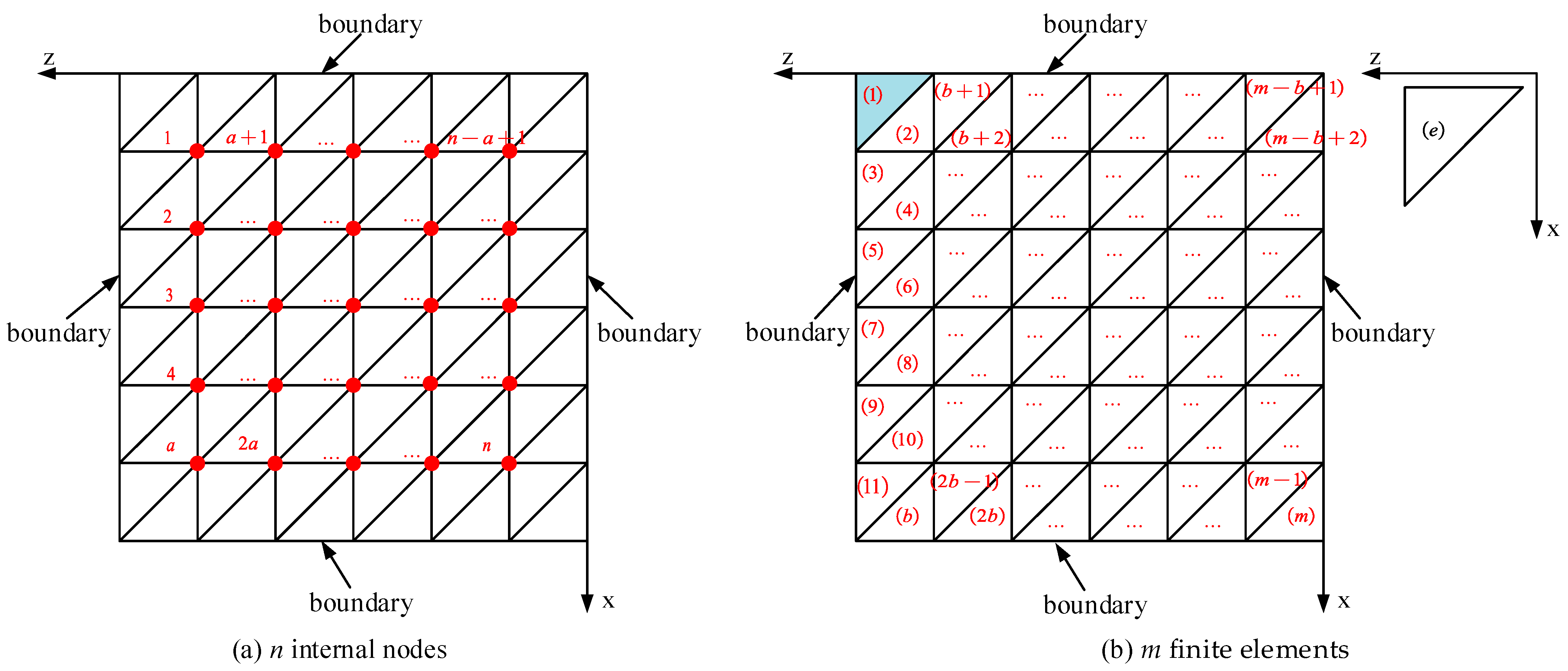
2.1. The Finite Element Formulation of the Reynolds Equation

The finite element formulation of the Reynolds equation divides the computational domain Ω into m finite elements and n internal nodes, as depicted in Figure 1. The gas Reynolds equation can be expressed as a sum of integrals over the area Δe of each element (e = 1, 2, 3, … m). In the computational domain Ω containing n nodes with pressure as the unknown function, only the elements associated with node i(i = 1, 2, 3 … n) have unknown variables. Therefore, the integral domain can also be expressed as e ∈ Δi. The finite element formulation of the gas Reynolds equation is as follows:
e Δ i Δ e N e T h e 3 d x ¯ d z ¯ c i c e T + b i b e T f e 1 2 Δ e 2 Q e Δ i λ c i u ¯ + b i w ¯ h e T Δ e N e N e T d x ¯ d z ¯ 1 2 Δ e f 1 / 2 e = 0 i = 1 , 2 , , n .
Since the aerostatic bearings considered in this paper do not account for bearing velocity, Equation (1) can be expressed in the following form:
e Δ i Δ e N e T h e 3 d x ¯ d z ¯ c i c e T + b i b e T f e 1 2 Δ e 2 Q = 0 i = 1 , 2 , , n
In this paper, linear triangular elements are chosen as the fundamental units for FEM. The three nodes of the triangle, arranged counterclockwise, are denoted as i, j, and m. The integral term in Equation (2) expands as follows:
Δ e N e T h e 3 d x ¯ d z ¯ = Δ e 10 h i ¯ + h j ¯ + h m ¯ h i ¯ 2 + h j ¯ 2 + h m ¯ 2 + h i ¯ h j ¯ h m ¯
Substituting Equation (3) into Equation (2) yields the functional form of the dimensionless steady-state Reynolds equation:
e Δ i 1 40 Δ e h i ¯ + h j ¯ + h m ¯ h i ¯ 2 + h j ¯ 2 + h m ¯ 2 + h i ¯ h j ¯ h m ¯ c i c e T + b i b e T f e Q = 0
The set of pressure distribution values that satisfy the dimensionless steady-state Reynolds Equation (4) constitutes a solution to the Reynolds equation. Applying the functional form of the Reynolds equation to n unknown nodes, denoted as i(i = 1, 2, …, n), yields the expression for the pressure function at these nodes. Expressed in matrix form, it is as follows:
K F T = 0
The primary focus in solving the finite element formulation of the Reynolds equation lies in the construction of the stiffness matrix K. In the equation, K represents the stiffness matrix; F = [f1 f2fn]T, where f represents the square of the pressure values at unknown nodes. T = [t1 t2tn]T, where t represents constant terms. During the construction of the stiffness matrix K, the pressure square terms associated with the atmospheric boundary and the air supply boundary nodes constitute the constant elements t in the T matrix.

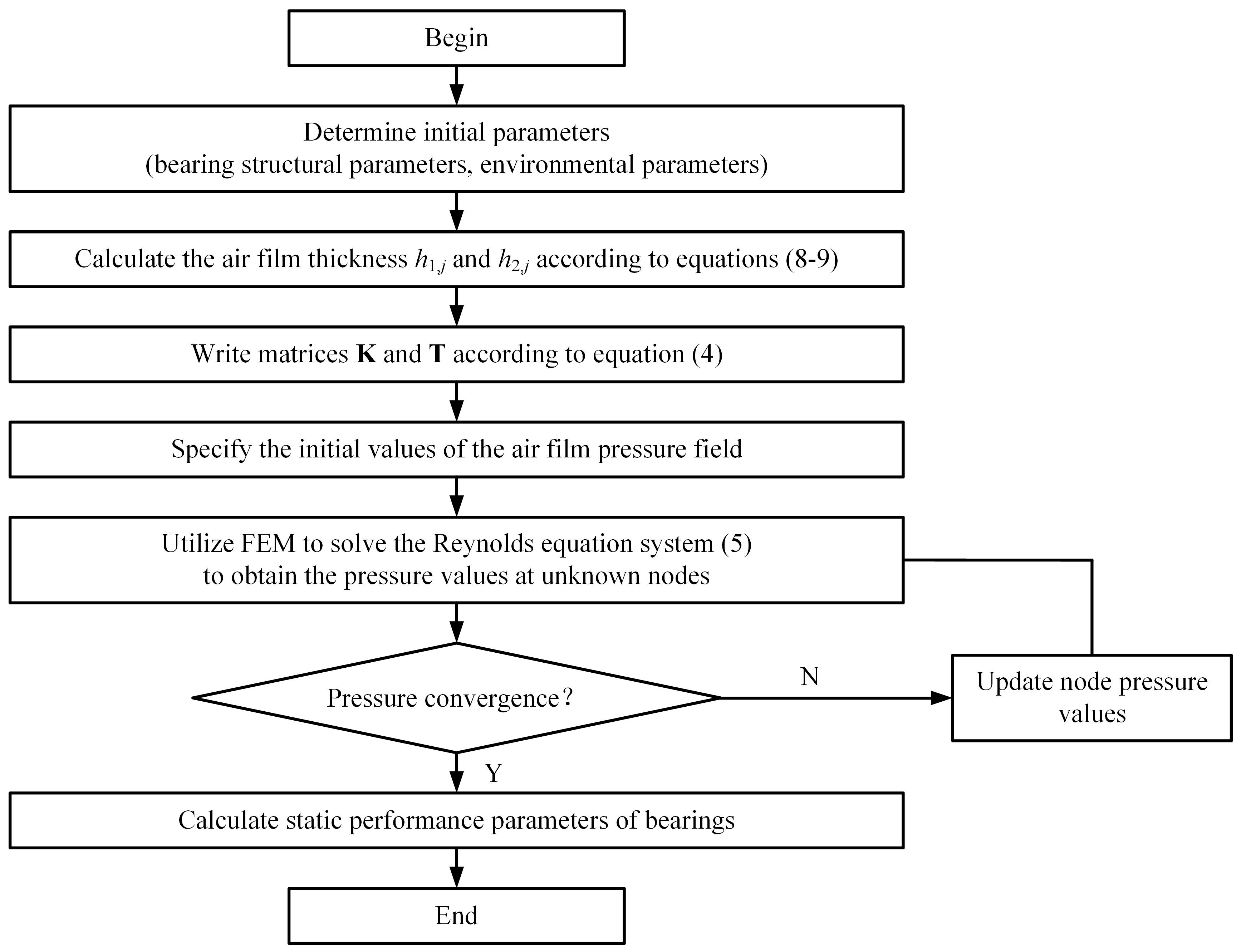
2.2. FEM Calculation for Surface-Throttling Aerostatic Bearings

The surface-throttling piston used in this study consists of two individual aerostatic bearings with identical structural dimensions. To simplify calculations, subsequent analysis will focus solely on a single aerostatic bearing of the piston, as depicted in Figure 2. The coordinate system is represented by capital letters XYZ, where the X-axis represents the width direction of the air film, Y-axis and Z-axis represent the thickness direction of the air film.
External compressed air enters the gap between the aerostatic bearing and the cylinder wall through the bottom of the cylinder, forming an air film between the aerostatic bearing and the inner wall of the cylinder, providing support for the aerostatic bearing. Under no external force, the center of the bearing is located at position O1. However, when the aerostatic bearing is subjected to external force and deflects, the center of the bearing O1 shifts to O2. This displacement of the center generates a change in the thickness of the air film between the aerostatic bearing and the cylinder, resulting in radial bearing capacity to counteract the external force. The formulas for calculating the thickness of the air film at the front and rear ends of the aerostatic bearing when it deflects are as follows:
h 1 = h m 1 × 1 ε 1 × cos θ
h 2 = h m 2 × 1 ε 2 × cos θ
In the equation, h1 represents the air film thickness at the front end of the bearing, h2 represents the air film thickness at the rear end of the bearing, hm1 represents air film thickness at the front end of the bearing in the non-eccentric state, hm2 represents air film thickness at the rear end of the bearing in the non-eccentric state, ε1 represents the eccentricity at the front end of the bearing (ε1 = c/hm1), ε2 represents the eccentricity at the rear end of the bearing (ε2 = c/hm2), θ represents the angle at any point on the circumference, and c represents the eccentricity distance.
Compared to the diameter of the aerostatic bearing, the thickness h of the air film in the bearing clearance is typically very small. Therefore, the curvature of the air film can usually be neglected, and the air film in the aerostatic bearing clearance can be approximated as a plane. As illustrated in Figure 3b, the x-axis represents the width direction of the air film, the y-axis represents the thickness direction of the air film, and the z-axis represents the circumferential direction of the air film.
The existing FEM for solving the gas Reynolds equation (Equations (1)–(5)) are typically applicable to cases where the air film thickness in the flow field varies continuously. The flow rate term Q involved in these equations is often calculated using the orifice flow meter formula. However, for surface-throttling aerostatic bearings, factors such as discontinuous air film thickness at the throttling ridges and the inapplicability of the orifice flow meter formula make it impossible to use the original FEM for their solution. In order to analyze the fluid field characteristics of surface-throttling aerostatic bearings, the following improvements are made to the original FEM:
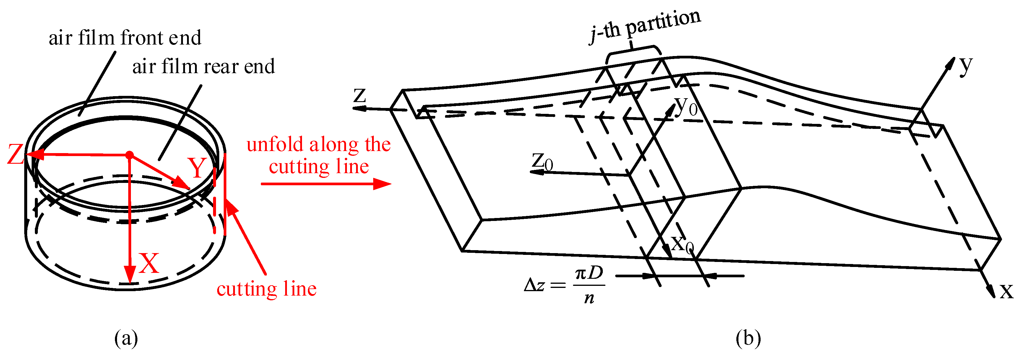
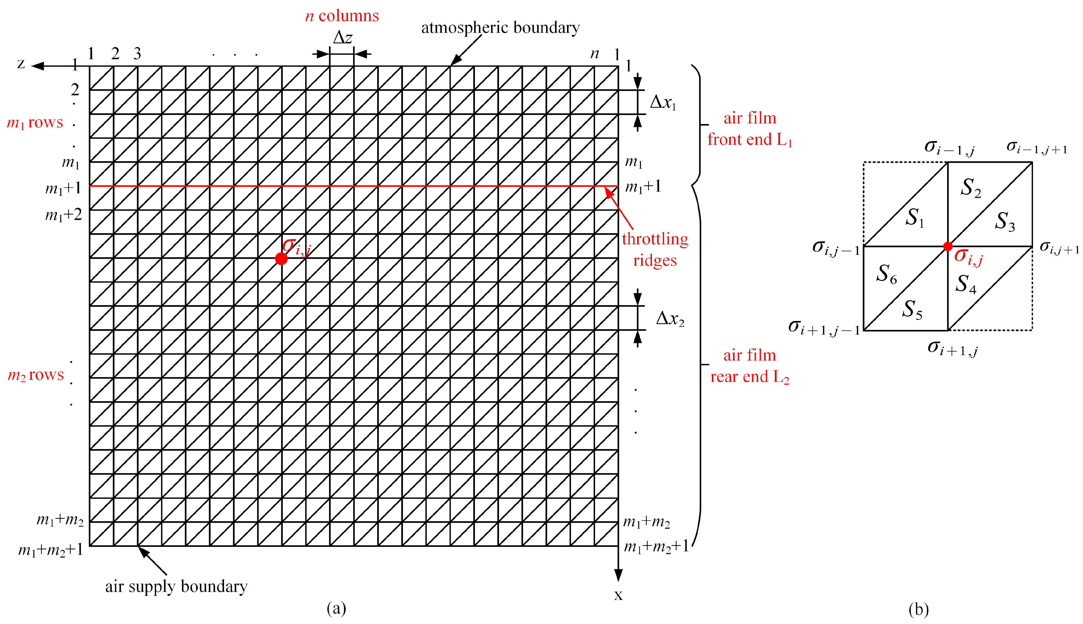
Partitioning of the air film calculation domain
The expanded air film between the aerostatic bearings is divided uniformly in the x and z directions into (m1 + m2) and n equal parts, respectively, as illustrated in Figure 4a. The entire computational domain is partitioned into 2n·(m1 + m2) linear triangular elements. The upper boundary of the computational domain corresponds to the atmospheric boundary, while the lower boundary corresponds to the air supply boundary. Therefore, there are n·(m1 + m2 − 1) unknown nodes in the entire computational domain. Figure 4b depicts six linear elements Sk (k = 1, 2, …, 6) associated with any node σi,j (2 ≤ Im1 + m2, 1 ≤ jn) in the air film computational domain, where i denotes the row number of the node, and j denotes the column number of the node.
When the aerostatic bearing deflects radially under external force, the thickness of the air film at each point in the circumferential direction varies, as illustrated in Figure 3b. The air film computational domain is uniformly divided into n equal parts in the z direction. According to Equations (6) and (7), the thickness of the air film at each node in each column can be expressed as follows:
h 1 , j = h m 1 × 1 ε 1 × cos j 1 × 2 π n 1 j n
h 2 , j = h m 2 × 1 ε 2 × cos j 1 × 2 π n 1 j n
The lengths of the air film at the front and rear ends of the air film computational domain in the x direction are denoted as L1 and L2, respectively. They are uniformly divided into m1 and m2 parts, respectively, with each segment having lengths represented by Δx1 and Δx2. Therefore, the area Δe of the triangular element at the front and rear ends of the air film can be expressed as:
Δ e 1 = 1 2 Δ x 1 × Δ z
Δ e 2 = 1 2 Δ x 2 × Δ z
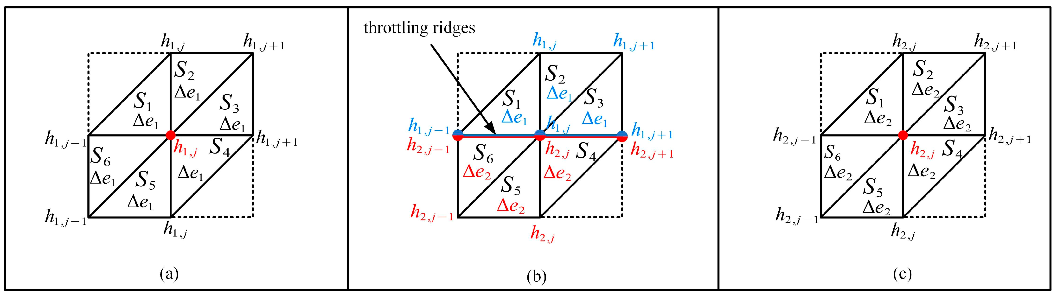
Specification of node air film thickness
In solving the Reynolds equation using FEM, the thickness of the air film at each node in the computational domain depends on the thickness of the air film in the element to which it belongs. When all elements are located at the front end of the air film, as shown in Figure 5a, the thickness of the air film at the nodes of these elements is determined by the thickness h1,j of the air film at the front end, and the area of the elements is represented by Δe1. For nodes located at the throttling ridges, as illustrated in Figure 5b, the thickness of the air film is specified as follows: when the element (S1, S2, S3) to which the node σi,j belongs is located at the front end of the air film, the thickness of the air film at that node is h1,j, and the area of the element is Δe1; when the element (S4, S5, S6) to which the node σi,j belongs is located at the rear end of the air film, the thickness of the air film at that node is h2,j, and the area of the element is Δe2. When all elements are located at the rear end of the air film, as depicted in Figure 5c, the thickness of the air film at the nodes of these elements is determined by the thickness h2,j of the air film at the rear end, and the area of the elements is represented by Δe2.
By setting variables for the air film thickness at the nodes of the front and rear ends of the air film and their respective elements, as well as specifying the air film thickness at the nodes of the throttle ridges, the surface-throttling aerostatic bearing can be effectively resolved even when the air film is discontinuous.
Calculation of flow rate for surface-throttling aerostatic bearings
As depicted in Figure 3b and Figure 4a, the circumferential direction of the air film is divided into n equal parts. For any arbitrary part j, it is assumed that the air flows in one dimension within the j-th part and there is no rotational motion. The air only flows along the negative x-direction (axial direction). At the throttling ridges, the air film gap experiences a sudden change due to surface-throttling, where the initial air pressure is Ps. As the air flows through the throttling ridges, the throttling effect causes the pressure to rapidly decrease to Pd. Therefore, the formula for calculating the flow rate of the surface-throttling aerostatic bearings can be obtained from the following equation:
Air motion equation:
P x = η 2 u y 2
P y = 0
P z = 0
Air state equation:
P ρ = P a ρ a
Mass continuity equation:
m i = Δ z 0 h 2 , j ρ u d y
By combining Equations (12)–(16), the formula for the flow rate in surface-throttling aerostatic bearings is as follows:
m = j = 1 n m j = j = 1 n P s 2 P d 2 Δ z h 2 , j 3 ρ a 24 η P a L 2
Since the existing flow calculation formula for orifice-throttling aerostatic bearings is not applicable to surface-throttling aerostatic bearings, this paper derives the flow rate for surface-throttling aerostatic bearings by substituting the pressure value Pd at the throttle ridges, obtained through improved FEM calculations, into Equation (17). By simultaneously solving Equations (4), (5) and (8)–(17), the dimensionless steady-state Reynolds equation can be obtained. The calculation process is illustrated in Figure 6.

3. Static Performance Calculation of Surface-Throttling Aerostatic Bearings

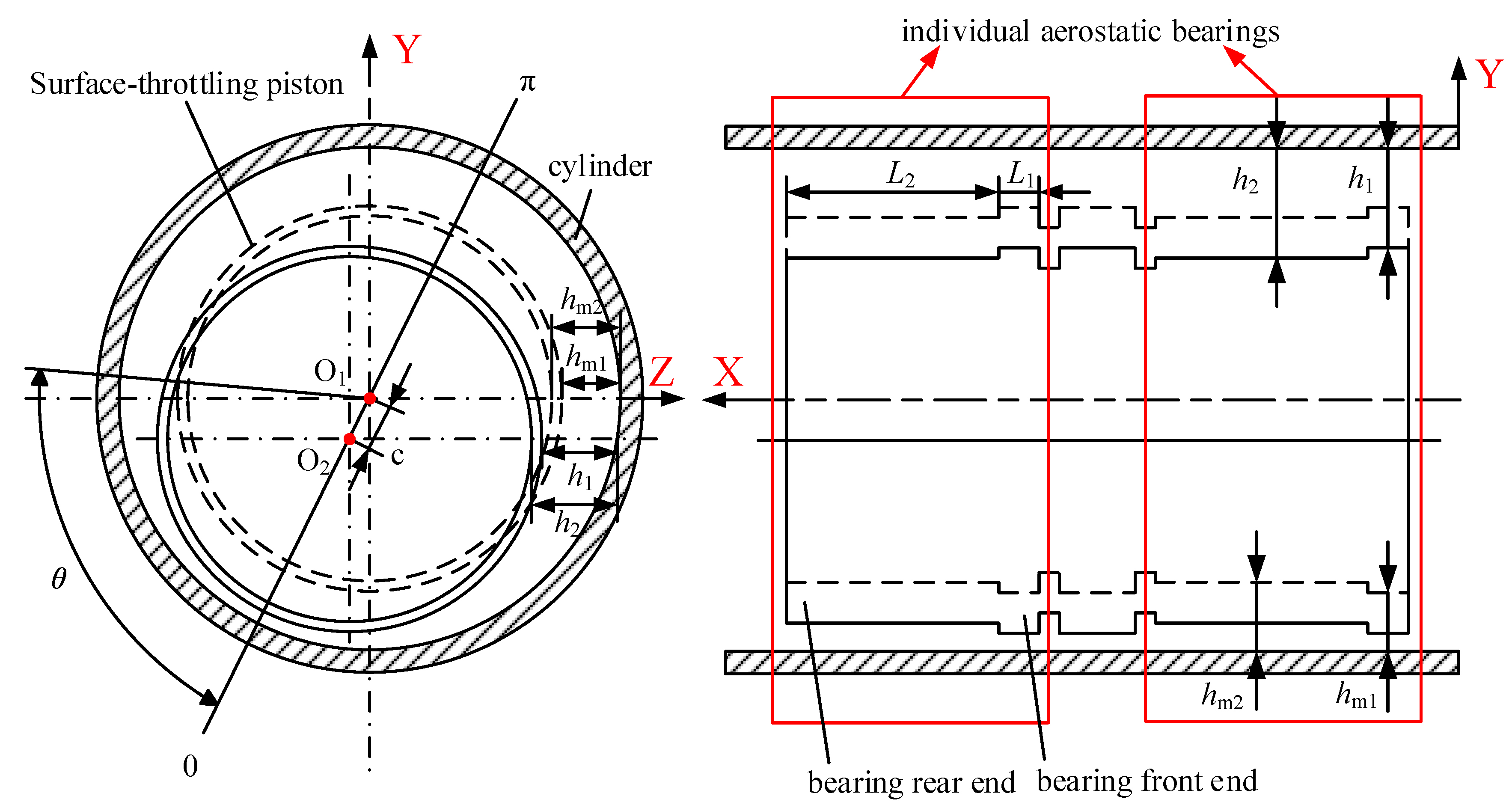
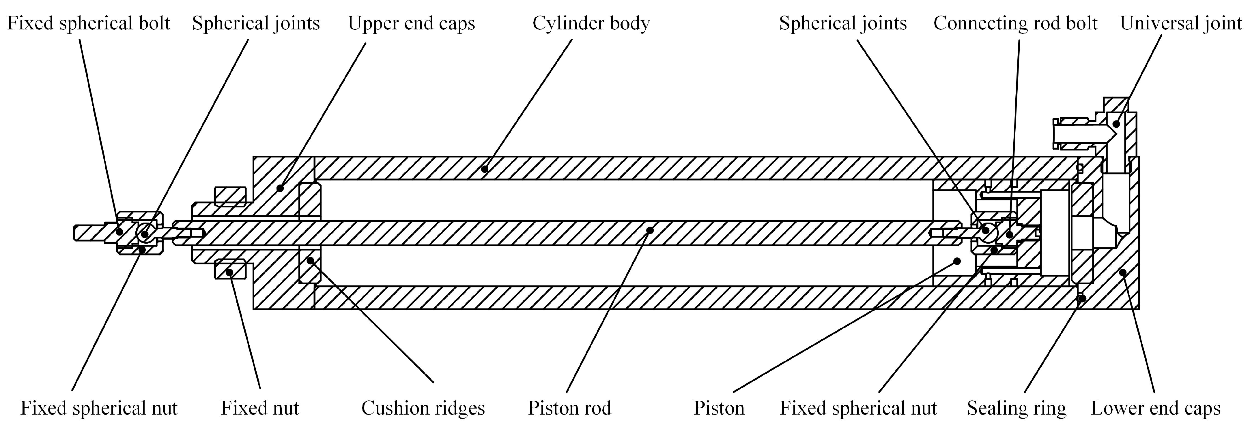
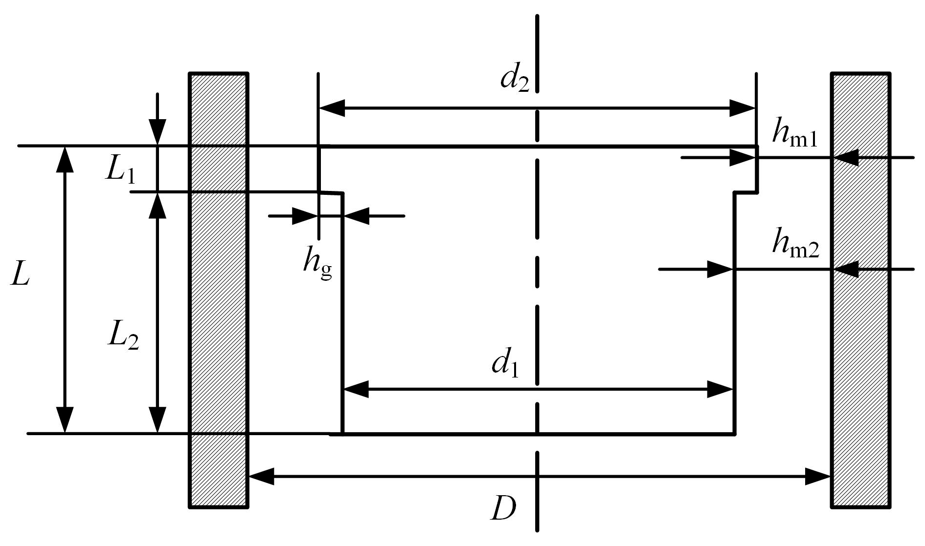
3.1. Structural Design and Operating Principles of Surface-Throttling Frictionless Pneumatic Cylinder

The structure of the surface-throttling frictionless pneumatic cylinder is illustrated in Figure 7. The cylinder structure consists of upper and lower end caps, cushion ridges, cylinder body, piston, piston rod, and so forth. Spherical joints are employed at both ends of the piston rod, facilitating the assembly adjustment between the piston rod and the vertical axis connection components of the ultra-precision machine tools. This design reduces the coaxiality requirements between the piston rod and the vertical axis connection components of traditional frictionless cylinders. Additionally, it prevents the swinging of the piston caused by the straightness error of the vertical axis, ensuring the stable operation of the cylinder.
The piston structure of the cylinder, as depicted in Figure 7, utilizes the surface-throttling principle. Throttling ridges are integrated into the piston surface for throttling. Surface-throttling, devoid of throttle holes, eliminates constraints on reducing the air film thickness, thus enhancing stiffness and reducing air flow to some extent. Additionally, vent holes are situated beneath the piston to alleviate pressure from both the upward and downward high-pressure air, thereby minimizing pressure differentials within the cylinder and preventing air backflow.
As shown in Figure 8, during the operation of the frictionless pneumatic cylinder, high-pressure air enters the cylinder through the lower end cap. A portion of the air flows into the gap between the piston and the cylinder body through the air supply holes on the piston, while the majority of the air passes through the surface-throttling ridges at point C on the piston surface, forming a pressure film through surface-throttling, and then continues to move upward and is discharged directly from the cylinder body. A small amount of air moves downward and enters the interior of the piston through the vent holes before being discharged from the cylinder body. Another portion of the air enters the gap between the piston and the cylinder body directly from the bottom of the piston. It then passes through the surface-throttling ridges at point D on the piston surface, forming a pressure film through surface-throttling, and moves upward to enter the interior of the piston through the vent holes before being discharged from the cylinder body.

3.2. Static Equilibrium Calculation of Surface-Throttling Aerostatic Bearings

Considering potential errors in machining and assembly of the vertical axis in practical applications, it is essential to ensure the continuous and reliable operation of the frictionless pneumatic cylinder. Therefore, static equilibrium calculation of the dual-cylinder system designed in this study is conducted, as illustrated in Figure 9.
The static equilibrium calculation of the dual-cylinder system under ideal conditions is illustrated in Figure 9a, where the cylinder piston is solely subjected to aerostatic support force. In actual scenarios, as depicted in Figure 9b, when deviation errors occur in the guide rail components due to manufacturing or assembly reasons, the cylinder piston also undergoes angular deviation under the influence of the piston rod. The specific static equilibrium calculation is depicted in Figure 9c.
The static equilibrium calculation of the guide rail components yields:
F s 1 sin α = F s 2 sin β
F s 1 cos α + F s 2 cos β = G
The static equilibrium calculation of the piston yields:
F 1 = F s 1 cos α
F w 1 = F s 1 sin α
F 2 = F s 2 cos β
F w 2 = F s 1 sin β
Furthermore, as illustrated in Figure 10, the minimum gap between the piston and the cylinder wall is the average thickness hm1 of the air film at the front end of the aerostatic bearing. Assuming the length of the piston rod is l, the maximum angular displacement of the piston driven by the piston rod between the inner walls of the cylinder is as follows:
0 tan α 2 h m 1 l 2 2 h m 1 2
0 tan β 2 h m 1 l 2 2 h m 1 2
The range of values for the support forces F1 and F2, as well as the radial bearing capacity Fw1 and Fw2, can be calculated by solving Equations (18)–(25) jointly, as follows:
1 2 G F 1 = G 1 + tan α / tan β G
1 2 G F 2 = G 1 + tan β / tan α G
0 F w 1 = F w 2 = G 1 / tan β + 1 / tan α G h m 1 l 2 2 h m 1 2
To ensure the frictionless pneumatic cylinder operates effectively, it is imperative that the piston possesses a certain radial bearing capacity Fw and sufficiently large support force F when there are errors in the vertical axis guide rail components of the ultra-precision machine tools. By conducting static equilibrium calculations on the dual-cylinder system, the range of values for the radial bearing capacity and support force of the frictionless pneumatic cylinder’s aerostatic bearings was determined. This provides a basis for selecting parameters for subsequent aerostatic bearing configurations.

3.3. Static Performance Calculation of Surface-Throttling Aerostatic Bearings Using FEM

The static performance of surface-throttling aerostatic bearings is influenced by several parameters. For surface-throttling aerostatic bearings, the key parameters affecting their static performance are the groove depth, groove length ratio, total length, and Length-to-Diameter Ratio. This study uses improved FEM to examine how these parameters affect the radial bearing capacity and air consumption of the aerostatic bearing piston. The structural parameters of the surface-throttling aerostatic bearing are illustrated in Figure 11.
The FEM model of the surface-throttling frictionless pneumatic cylinder is demonstrated in Figure 4. The computational domain is equally divided into n parts along the z-axis, while it is divided into (m1 + m2) parts along the x-axis. As the calculation results are sensitive to mesh resolution, the static performance of the surface-throttling frictionless pneumatic cylinder shown in Figure 11 was analyzed with varying mesh resolutions, and the detailed data of the tests are listed in Table 1. The calculations were conducted with an air source pressure of 0.5 MPa. As shown in the table, with further refinement of mesh resolution, the variations in radial bearing capacity and flow rate arelower than 0.1%. Therefore, Mesh 3 was adopted in this paper, considering both calculation efficiency and accuracy comprehensively.
Under conditions where other parameters are fixed, the influence of different air film thicknesses hm1 and throttle groove depth hg on the static characteristics is discussed at a constant eccentricity. From Figure 12a, it can be observed that for a constant air film thickness, a deeper groove results in higher bearing capacity. This is because the groove depth primarily affects the area of the throttling surface responsible for throttling. A deeper groove leads to a larger throttling area, resulting in increased bearing capacity. From Figure 12b, it can be seen that for smaller air film thicknesses, shallower throttle grooves lead to higher air film stiffness, while for larger air film thicknesses, increasing the depth of the throttle groove tends to increase stiffness.
The air film thickness and throttle groove depth directly affect the dimensions of the bearing, thereby influencing its air consumption. The impact on air consumption is illustrated in Figure 12c, where the air consumption of the bearing increases with the increase in air film thickness and groove depth. Specifically, as the air film thickness increases, the effect of the throttle groove depth on air consumption becomes more pronounced.
Under conditions where other parameters are fixed, the influence of different air film thicknesses hm1 and groove length ratio L2/L on the static characteristics is discussed at a constant eccentricity. From Figure 13a,b, it can be observed that both the bearing capacity and stiffness of the bearing decrease with increasing air film thickness. When the air film thickness is constant, increasing the groove length ratio initially increases both the bearing capacity and stiffness, followed by a decrease. Figure 13c shows the curve of the groove length ratio L2/L on the flow rate, where the flow rate increases with increasing air film thickness. When the air film thickness is constant, the flow rate decreases with increasing groove length ratio.
Under conditions where other parameters are fixed, the influence of different air film thicknesses hm1 and total length L on the static characteristics is discussed at a constant eccentricity. From Figure 14a,b, it can be observed that both the bearing capacity and stiffness of the bearing decrease with increasing air film thickness. When the air film thickness is constant, increasing the total length of the bearing leads to a gradual increase in both bearing capacity and stiffness. Figure 14c shows the curve of the total length of the bearing on the flow rate, where the flow rate increases with increasing air film thickness. When the air film thickness is constant, the flow rate decreases with increasing total length of the bearing.
Under conditions where other parameters are fixed, the influence of different air film thicknesses hm1 and length-to-diameter ratio L/D on the static characteristics is discussed at a constant eccentricity. From Figure 15a,b, it can be observed that both the bearing capacity and stiffness of the bearing decrease with increasing air film thickness. When the air film thickness is constant, increasing the length-to-diameter ratio of the bearing leads to a gradual decrease in both bearing capacity and stiffness. Figure 15c shows the curve of the length-to-diameter ratio of the bearing on the flow rate, where the flow rate increases with increasing air film thickness. When the air film thickness is constant, the flow rate decreases with increasing length-to-diameter ratio of the bearing.
In order to find the optimal parameters for surface-throttling aerostatic bearings, maximizing radial bearing capacity while minimizing air consumption issought. Based on the effects of parameters such as groove depth (hg), groove length ratio (L2/L), total length (L), and length-to-diameter ratio (L/D) on the radial bearing capacity, stiffness, and flow rate of the surface-throttling aerostatic bearing, combined with the existing manufacturing capabilities. The following structural parameters are chosen: groove depth (hg) of 5 μm, groove length ratio (L2/L) of 80%, total length (L) of 17 mm, length-to-diameter ratio (L/D) of 50%, and average air film thickness (hm1) of 10 μm.
According to the dual-cylinder system discussed in this paper, measurements reveal the gravity of the guide component (G) to be 600 N, with a piston rod length (l) of 250 mm. In practical operation, the supply pressure (Ps) ranges from 0.5 to 0.7 MPa. Through static equilibrium calculation of the dual-cylinder system, the support force and radial bearing capacity of the surface-throttling frictionless pneumatic cylinder fall within the ranges (Equations (26)–(28)), yielding the following results: the aerostatic bearing’s bottom area (S) ranges from 8.57 × 10⁻⁴ m2 to 1.2 × 10⁻³ m2, and the radial bearing capacity ranges from 0 to 0.024 N. By comparing these results with those obtained from FEM of the surface-throttling aerostatic bearing, it is evident that both the bottom area and the radial bearing capacity far exceed the design requirements, demonstrating their ability to meet the operational demands of the cylinder effectively.

4. Verification and Discussion

4.1. Verification of CFD Calculation Results

To validate the reliability of the FEM proposed in this paper for surface-throttling aerostatic bearings, the existing CFD calculation was utilized to calculate the radial bearing capacity and flow rate of the surface-throttling aerostatic bearings under different eccentricity conditions, while keeping other computational parameters consistent with chapter three. The specific steps are as follows: Firstly, the three-dimensional model of the aerostatic bearing fluid domain under zero-eccentricity condition was constructed. Hexahedral elements were then used for meshing, with mesh refinement applied at the pressure inlet, pressure outlet, and throttling protrusion to ensure resultsaccuracy. The meshed CFD model and boundary conditions are depicted in Figure 16a. Subsequently, CFD software was employed to set up and analyze the aerostatic bearing. The pressure inlet was set to 0.5 MPa, and the pressure outlet boundary condition was atmospheric pressure. The resulting pressure distribution is shown in Figure 16b. This process was repeated for different eccentricity values.
To balance the accuracy of simulation results and simulation efficiency, it is desirable to achieve high simulation accuracy with a relatively small number of grids. Based on the parameters of the surface-throttling aerostatic bearing shown in lines 426–428, CFD simulations were performed using six different grid quantities:3.29 × 10⁴, 5.09 × 10⁴, 1.31 × 10⁵, 3.67 × 10⁵, 3.28 × 10⁶, and 5.24 × 10⁶. The grid independence verification of the simulation is shown in Figure 17. As depicted in Figure 17, when the number of grids reaches 3.67 × 10⁵, further increasing the number of grids results in negligible changes in the radial bearing capacity and flow rate of the aerostatic bearings. Therefore, for subsequent simulations, a grid size of 3.67 × 10⁵ will be used for analysis.
The CFD results for aerostatic bearings under different eccentricities are illustrated in Figure 18. The radial bearing capacity and flow rate computed using the improved FEM proposed in this paper generally align with the trends observed in the CFD results, showing only minor discrepancies in local numerical values. With the results from the existing CFD calculation serving as reference values, the maximum calculation error for radial bearing capacity using the improved FEM in this study is 6%, while the maximum error for flow rate is 7%.
The calculation errors obtained using the improved FEM fall within an acceptable range, indicating the reliability of the FEM proposed in this paper for surface-throttling aerostatic bearings. When compared with results from existing CFD calculation, it is observed that as the eccentricity of the aerostatic bearing increases, the calculation errors of both radial bearing capacity and flow rate also increase. The primary reason for this phenomenon is that the dimensions of the throttle protrusion in the surface-throttling aerostatic bearings considered in this paper are particularly small. As eccentricity gradually increases, the mesh quality of the bearing unavoidably decreases, leading to an increase in the calculation errors of both radial bearing capacity and flow rate.

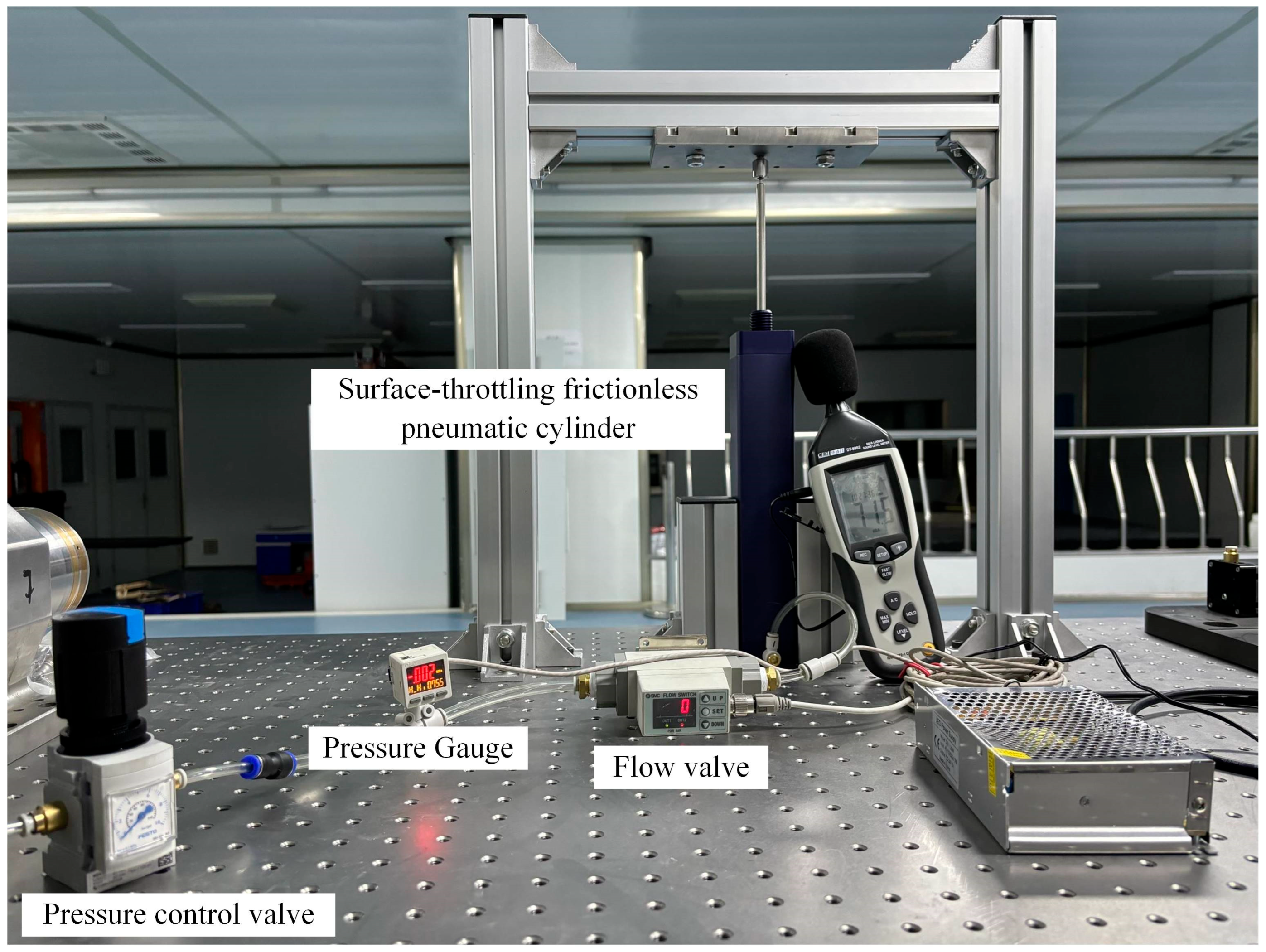
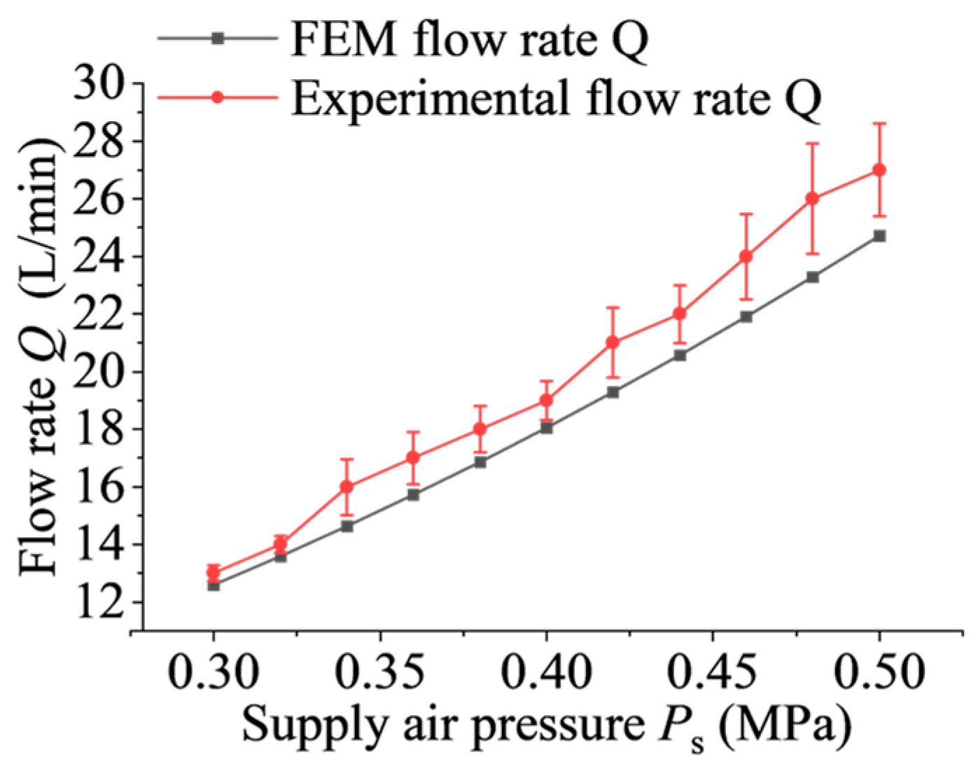
4.2. Experimental Verification

To validate the accuracy of the results, a test rig was specifically constructed to evaluate the performance of the frictionless pneumatic cylinder. When the bearing operates normally, the radial bearing capacity exists within the frictionless pneumatic cylinder and cannot be directly measured. Therefore, the experiment verified the data by measuring the flow rate of the frictionless pneumatic cylinder under different pressures. The test rig of the flow rate detection device for the frictionless pneumatic cylinder is depicted in Figure 19.
The experimental data on the variation of flow rate with supply air pressure for the aerostatic bearings were obtained, and the results were compared with those obtained from the improved FEM proposed in this paper, as shown in Figure 20. It can be observed that the experimentally measured flow rate generally corresponds to the trends predicted by the improved FEM, with minor discrepancies in local numerical values. The maximum error in flow rate is 10%, which falls within an acceptable range of deviation. Therefore, the proposed improvement to the FEM for surface-throttling aerostatic bearings exhibits reliability.
To verify the static equilibrium calculation of the dual-cylinder system addressed in this paper, the following experiment was designed. The experimental setup, as shown in Figure 21, mainly consists of a pressure gauge, an ultra-precision vertical axis, two frictionless pneumatic cylinders, and counterweights. The straightness of the ultra-precision vertical axis is 0.089 um within a stroke range of 0–150 mm. In the experiment, counterweights were sequentially added to the ultra-precision machine tool’s vertical axis to change the load on the cylinders. The pressure values of both cylinders during the steady ascent and descent were recorded using the pressure gauge. The measured values represent the average of multiple experiments, and all pressure values are relative. The experimental test results are presented in Table 1.
The main objective of this experiment isto compare the pressure values of the frictionless pneumatic cylinders during slow ascent and descent under different loads with the theoretically calculated pressure values for a single cylinder. According to the experimental results in Table 1, it can be observed that the pressure differentials of the frictionless pneumatic cylinders during slow ascent and descent areboth below 0.003 MPa. This meets the criterion that the friction pressure of the frictionless pneumatic cylinder should be less than 0.005 MPa [15], indicating that the piston inside the cylinder remains suspended within the cylinder during the slow ascent and descent of the frictionless pneumatic cylinder. Furthermore, according to the experimental results, it can be noted that due to the inherent straightness error of the ultra-precision vertical axis, there exists a slight difference in the pressure values of the two frictionless pneumatic cylinders during slow ascent and descent. This validates the static equilibrium calculation for the dual-cylinder system as discussed in chapter three.

4.3. Comparison of Computational Efficiency between the Improved FEM and CFD Calculation

Table 2 provides a detailed comparison of the computation times between the improved FEM proposed in this paper and the existing CFD calculation. Specifically, the computation time of the existing CFD calculation includes the time for CFD model establishment, mesh generation, and post-processing. By comparing the computation times of both methods under different eccentricities, it can be observed that the average computation time of the existing CFD calculation isapproximately 8.329 h, while the average computation time of the proposed improved FEM in this paper decreased to 51.392 s, as shown in Table 3. This significant improvement in computational efficiency isachieved while ensuring computational accuracy.

5. Conclusions

This paper proposes an improved FEM for the static performance calculation of surface-throttling frictionless pneumatic cylinder. It specifically focuses on computing the radial bearing capacity and support force of the pneumatic cylinder. This method effectively addresses the difficulties in using the FEM approach for calculating the surface-throttling aerostatic bearings caused by the discontinuity of the air film. Using the dual-cylinder system discussed in this paper as a case study, the structure and relevant static performance of surface-throttling frictionless pneumatic cylinders were investigated. The accuracy of the computations was verified through existing CFD calculation and experiments. According to the research in this paper, the major conclusions are drawn as follows:
  • The improved FEM proposed in this paper addresses the computational challenge of varying air film thickness at different locations within surface-throttling aerostatic bearings. It overcomes the difficulties associated with variations in element air film thickness at different bearing positions. Additionally, it offers insights into the calculation of flow rate for surface-throttling aerostatic bearings.
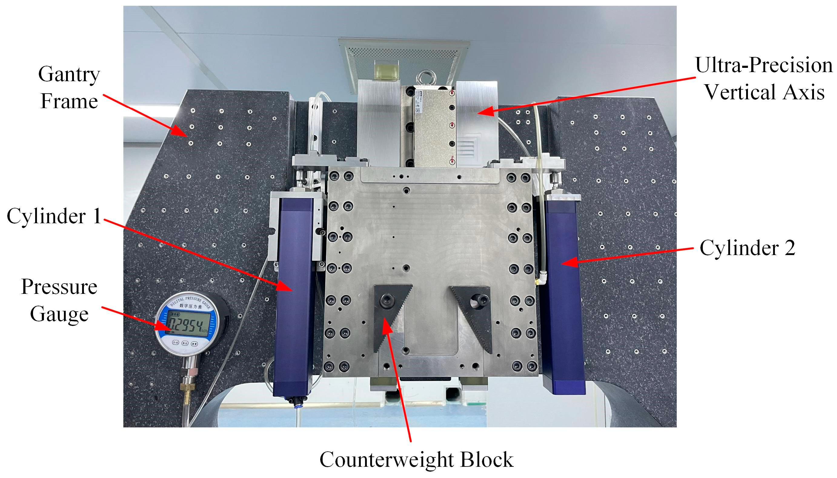
  • Static equilibrium calculations were performed for the dual-cylinder system, considering the inherent errors in the ultra-precision machine tool’s vertical axis. This process yielded a range of radial bearing capacity and support force values for the frictionless pneumatic cylinders, offering theoretical guidance for selecting cylinder parameters.
  • The improved FEM proposed in this paper has been validated through comparisons with the CFD calculation and experimental data. For the cylinders in this paper, the errors between the improved FEM and the CFD calculation are6% for radial bearing capacity and 7% for flow rate, respectively. The error between the calculated flow rate and the experimental data is 10%. While there are slight discrepancies in local numerical values, the overall trends in the computed results closely match.
  • The computational efficiency of the proposed FEM model is significantly improved compared with the CFD calculation. For the cylinders in this paper, the average computation time decreased from 8.329 h to 51.392 s.

Author Contributions

Conceptualization, J.X.; Data curation, Y.L.; Formal analysis, J.X. and L.Q.; Funding acquisition, S.G., Q.G. and L.L.; Investigation, J.X., L.Q. and M.Z.; Methodology, J.X. and H.Y.; Software, J.X. and M.Z.; Supervision, W.W.; Validation, H.Y.; Visualization, J.X.; Writing—Original draft, J.X.; Writing—review and editing, Q.G. All authors have read and agreed to the published version of the manuscript.

Funding

This research was funded by The National Key Research and Development Program of China, the funding number: 2022YFB3402705, the funder: Lihua Lu; The National Natural Science Foundation of China, the funding number: 52105439, the funder: Qiang Gao; The Key research and development program of Heilongjiang Province, the funding number: 2022ZX03A05, the funder: Siyu Gao; Manufacturing science and technology innovation talent project of Harbin, the funding number: 2023CXRCGD028, the funder: Siyu Gao.

Data Availability Statement

Data are contained within the article.

Conflicts of Interest

The authors declare no conflicts of interest.

References

  1. Xing, T.; Zhao, X.; Song, L.; Cui, Z.; Zou, X.; Sun, T. On-Machine Measurement Method and Geometrical Error Analysis in a Multi-Step Processing System of an Ultra-Precision Complex Spherical Surface. J. Manuf. Process. 2022, 80, 161–177. [Google Scholar] [CrossRef]
  2. Hatefi, S.; Abou-El-Hossein, K. Review of Single-Point Diamond Turning Process in Terms of Ultra-Precision Optical Surface Roughness. Int. J. Adv. Manuf. Technol. 2020, 106, 2167–2187. [Google Scholar] [CrossRef]
  3. Pu, X.; Xu, J.; Huang, P.; Du, H.; Zhu, Z. Fast Tool Servo-Based Ultra-Precision Diamond Sculpturing for Fabricating Micro-Structured Surfaces. Int. J. Mech. Sci. 2024, 263, 108790. [Google Scholar] [CrossRef]
  4. Zhang, H.; Xiang, S.; Wu, C.; Yang, J. Optimal Proportion Compensation Method of Key Geometric Errors for Five-Axis Machine Tools Considering Multiple-Direction Coupling Effects. J. Manuf. Process. 2024, 110, 447–461. [Google Scholar] [CrossRef]
  5. Shi, W.; Chunqiang, Y.; Tai, Y.; Yupeng, W.; Yong, Z. Comprehensive Analysis and Evaluation of the Geometric Errors of the Rotating Axis of Five-Axis Double-Pendulum Machine Tools Based on S-Shaped Samples. Int. J. Adv. Manuf. Technol. 2023, 129, 5135–5148. [Google Scholar] [CrossRef]
  6. Wang, J.; Guo, J. The Identification Method of the Relative Position Relationship between the Rotary and Linear Axis of Multi-Axis Numerical Control Machine Tool by Laser Tracker. Measurement 2019, 132, 369–376. [Google Scholar] [CrossRef]
  7. Takahashi, M.; Yoshioka, H.; Shinno, H. A Newly Developed Long-Stroke Vertical Nano-Motion Platform with Gravity Compensator. J. Adv. Mech. Des. Syst. Manuf. 2008, 2, 356–365. [Google Scholar] [CrossRef]
  8. Park, C.H.; Song, C.K.; Hwang, J.; Kim, B.-S. Development of an Ultra Precision Machine Tool for Micromachining on Large Surfaces. Int. J. Precis. Eng. Manuf. 2009, 10, 85–91. [Google Scholar] [CrossRef]
  9. Hsieh, M.-F.; Tung, C.-J.; Yao, W.-S.; Wu, M.-C.; Liao, Y.-S. Servo Design of a Vertical Axis Drive Using Dual Linear Motors for High Speed Electric Discharge Machining. Int. J. Mach. Tools Manuf. 2007, 47, 546–554. [Google Scholar] [CrossRef]
  10. Raparelli, T.; Mazza, L.; Trivella, A. Experimental Analysis and Preliminary Model of Non-Conventional Lip Seals. Tribol. Int. 2023, 181, 108311. [Google Scholar] [CrossRef]
  11. Xu, X.; Zhang, Y. Effect of Different Chemical Conversion Coatings on the Tribological Performance of Cylindrical Thrust Roller Bearings under Conditions of Dry Friction and Solid Lubrication. Wear 2024, 548, 205351. [Google Scholar] [CrossRef]
  12. Zhang, B.; Ma, X.; Liu, L.; Wang, Y.; Yu, H.; Morina, A.; Lu, X. Reciprocating Sliding Friction Behavior and Wear State Transition Mechanism of Cylinder Liner and Piston Ring. Wear 2024, 546, 205293. [Google Scholar] [CrossRef]
  13. Wang, G.; Li, W.; Liu, G.; Feng, K. A Novel Optimization Design Method for Obtaining High-Performance Micro-Hole Aerostatic Bearings with Experimental Validation. Tribol. Int. 2023, 185, 108542. [Google Scholar] [CrossRef]
  14. Gao, Q.; Chen, W.; Lu, L.; Huo, D.; Cheng, K. Aerostatic Bearings Design and Analysis with the Application to Precision Engineering: State-of-the-Art and Future Perspectives. Tribol. Int. 2019, 135, 1–17. [Google Scholar] [CrossRef]
  15. Yao, Y.; Zhang, K.; Yu, Z.; Mei, T. Research on a New Frictionless Air Cylinder. In Advanced Design Technology, PTS 1–3; Gao, J., Ed.; Trans Tech Publications Ltd.: Zurich, Switzerland, 2011; Volume 308–310, pp. 859–863. [Google Scholar]
  16. Zhu, X.; Jin, X.; Yao, B.; Cao, J. Modeling and Design of a Frictionless Pneumatic Cylinder System with Air Bearings. In Proceedings of the 2015 IEEE International Conference on Cyber Technology in Automation, Control, and Intelligent Systems (Cyber), Shenyang, China, 8–12 June 2015; pp. 1192–1197. [Google Scholar]
  17. Qian, P.; Liu, L.; Wu, J.; Pu, C.; Luo, H.; Fu, Y.; Zuo, Q. A Novel Double-Acting, Air-Floating, Frictionless Pneumatic Actuator. Sens. Actuators A Phys. 2023, 362, 114674. [Google Scholar] [CrossRef]
  18. Yu, P.; Huang, L.; Li, S.; Guo, L.; Zhong, M.; Zhang, L. Theoretical Predictions and Experimental Measurements of Novel Aerostatic Bearing with Multi-Inclined-Orifice Restrictors for the Improvement of Stability. Precis. Eng.-J. Int. Soc. Precis. Eng. Nanotechnol. 2024, 88, 266–278. [Google Scholar] [CrossRef]
  19. Kwan, Y.B.P.; Post, J.B. A Tolerancing Procedure for Inherently Compensated, Rectangular Aerostatic Thrust Bearings. Tribol. Int. 2000, 33, 581–585. [Google Scholar] [CrossRef]
  20. Talukder, H.M.; Stowell, T.B. Pneumatic Hammer in an Externally Pressurized Orifice-Compensated Air Journal Bearing. Tribol. Int. 2003, 36, 585–591. [Google Scholar] [CrossRef]
  21. Li, Y.F.; Yin, Y.H.; Yang, H.; Liu, X.E.; Mo, J.; Cui, H.L. Micro-Vibration Analysis and Optimization of Aerostatic Bearing with Pocketed Orifice-Type Restrictor. J. Appl. Fluid Mech. 2018, 11, 1115–1124. [Google Scholar] [CrossRef]
  22. Yoshimura, T.; Hanafusa, T.; Kitagawa, T.; Hirayama, T.; Matsuoka, T.; Yabe, H. Clarifications of the Mechanism of Nano-Fluctuation of Aerostatic Thrust Bearing with Surface Restriction. Tribol. Int. 2012, 48, 29–34. [Google Scholar] [CrossRef]
  23. Qi, L.; Liu, L.; Gao, Q.; Yao, Y.; Lu, L.; Gao, S. Investigation on the Influence of Structural Rigidity on the Stiffness of Aerostatic Guideway Considering Fluid-Structure Interaction. Tribol. Int. 2022, 173, 107658. [Google Scholar] [CrossRef]
  24. Belforte, G.; Raparelli, T.; Trivella, A.; Viktorov, V.; Visconte, C. CFD Analysis of a Simple Orifice-Type Feeding System for Aerostatic Bearings. Tribol. Lett. 2015, 58, 25. [Google Scholar] [CrossRef]
  25. Gao, S.; Cheng, K.; Chen, S.; Ding, H.; Fu, H. CFD Based Investigation on Influence of Orifice Chamber Shapes for the Design of Aerostatic Thrust Bearings at Ultra-High Speed Spindles. Tribol. Int. 2015, 92, 211–221. [Google Scholar] [CrossRef]
  26. Chen, Y.S.; Chiu, C.C.; Cheng, Y.D. Influences of Operational Conditions and Geometric Parameters on the Stiffness of Aerostatic Journal Bearings. Precis. Eng.-J. Int. Soc. Precis. Eng. Nanotechnol. 2010, 34, 722–734. [Google Scholar] [CrossRef]
  27. Yoshimoto, S.; Yamamoto, M.; Toda, K. Numerical Calculations of Pressure Distribution in the Bearing Clearance of Circular Aerostatic Thrust Bearings with a Single Air Supply Inlet. J. Tribol.-Trans. ASME 2007, 129, 384–390. [Google Scholar] [CrossRef]
Figure 1. The diagram of internal nodes and elements of the computational domain Ω.
Lubricants 12 00254 g001
Figure 2. Schematic diagram of surface-throttling piston structure.
Lubricants 12 00254 g002
Figure 3. Schematic diagram of surface-throttling aerostatic bearings air film: (a) Structural diagram of individual aerostatic bearings air film; (b) Schematic diagram of air film thickness distribution.
Lubricants 12 00254 g003
Figure 4. Calculation domain for the air film in surface-throttling aerostatic bearings: (a) Grid meshing; (b) Elements associated with node σi,j.
Lubricants 12 00254 g004
Figure 5. Nodes in the computational domain of surface-throttling aerostatic bearings: (a) Computational domain of the air film front end; (b) Computational domain at the throttling ridges; (c) Computational domain of the air film rear end.
Lubricants 12 00254 g005
Figure 6. Flowchart of the FEM for surface-throttling aerostatic bearings.
Lubricants 12 00254 g006
Figure 7. Simplified diagram of surface-throttling frictionless pneumatic cylinder.
Lubricants 12 00254 g007
Figure 8. Surface-throttling piston structure and air flow diagram.
Lubricants 12 00254 g008
Figure 9. Static equilibrium calculation of dual-cylinder system: (a) Dual-cylinder system in an ideal condition; (b) Dual-cylinder system in the actual condition; (c) Static equilibrium calculation of dual-cylinder system in the actual condition.
Lubricants 12 00254 g009
Figure 10. The maximum deflection angle of the piston.
Lubricants 12 00254 g010
Figure 11. Schematic diagram of structural parameters for a single aerostatic bearing.
Lubricants 12 00254 g011
Figure 12. Influence of groove depth on bearing static performance: (a) Variation curve of radial bearing capacity with air film thickness at different groove depths; (b) Variation curve of stiffness with air film thickness at different groove depths; (c) Variation curve of flow rate with air film thickness at different groove depths.
Lubricants 12 00254 g012
Figure 13. Influence of groove length ratio on bearing static performance: (a) Variation curve of radial bearing capacity with air film thickness at different groove length ratios; (b) Variation curve of stiffness with air film thickness at different groove length ratios; (c) Variation curve of flow rate with air film thickness at different groove length ratios.
Lubricants 12 00254 g013
Figure 14. Influence of total length on bearing static performance: (a) Variation curve of radial bearing capacity with air film thickness at different total lengths; (b) Variation curve of stiffness with air film thickness at different total lengths; (c) Variation curve of flow rate with air film thickness at different total lengths.
Lubricants 12 00254 g014
Figure 15. Influence of length-to-diameter ratio on bearing static performance: (a) Variation curve of radial bearing capacity with air film thickness at different length-to-diameter ratios; (b) Variation curve of stiffness with air film thickness at different length-to-diameter ratios; (c) Variation curve of flow rate with air film thickness at different length-to-diameter ratios.
Lubricants 12 00254 g015
Figure 16. CFD numerical calculation processing: (a) CFD model; (b) Pressure contour plot.
Lubricants 12 00254 g016
Figure 17. Mesh independence test: (a) Radial bearing capacity simulation grid independence curve; (b) Flow rate simulation grid independence curve.
Lubricants 12 00254 g017
Figure 18. Comparison between CFD calculation and FEM: (a) Comparison of radial bearing capacity between CFD calculation and FEM at different eccentricities; (b) Comparison of flow rates between CFD calculation and FEM at different eccentricities.
Lubricants 12 00254 g018
Figure 19. Schematic of flow rate detection device for frictionless pneumatic cylinder.
Lubricants 12 00254 g019
Figure 20. Comparison of flow rates between the improved FEM and experimental results.
Lubricants 12 00254 g020
Figure 21. Experimental setup of dual-cylinder system for vertical axis of ultra-precision machine tool.
Lubricants 12 00254 g021
Table 1. Mesh independence test of the FEM model of surface-throttling frictionless pneumatic cylinder.
Mesh(m1 + m2) × nRadial Bearing Capacity W (N)Flow Rate Q (L/min)
115 × 206.80088563824.88392443
230 × 406.94999043124.88348226
360 × 806.98773334624.88336807
490 × 1206.9947412124.88334682
Table 2. Test results of dual-cylinder system.
Cylinder 1Cylinder 2
Total Load (F + G)/kgPressure during Slow Ascension
/MPa
Pressure during Slow Descent
/MPa
Pressure Differential/MPaPressure during Slow Ascension
/MPa
Pressure during Slow Descent
/MPa
Pressure Differential/MPa
66.5080.33530.33420.00110.3350.33450.0005
67.3330.33980.33690.00290.33940.3370.0024
68.1580.34260.33990.00270.34220.33930.0029
68.9830.34610.34410.0020.3460.3450.001
69.8080.35050.34790.00260.35080.34790.0029
Table 3. Comparison of computation times between the improved FEM and CFD calculation.
Different
Eccentricities (μm)
CFD Calculation/(h)FEM/(s)
CFD Model Setup
/(h)
Mesh Generation
/(h)
Post-Processing
/(h)
00.453.154.2550.49
0.0010.563.414.2650.70
0.0020.533.454.2751.16
0.0030.623.484.2251.55
0.0040.613.524.4952.09
0.0050.583.684.4552.36
Average0.5583.4484.32351.392
Total8.32951.392
Disclaimer/Publisher’s Note: The statements, opinions and data contained in all publications are solely those of the individual author(s) and contributor(s) and not of MDPI and/or the editor(s). MDPI and/or the editor(s) disclaim responsibility for any injury to people or property resulting from any ideas, methods, instructions or products referred to in the content.

