Article

Friction and Wear Mechanisms of Ti3SiC2/Cu Composites under the Synergistic Effect of Velocity–Load Field at 800 °C

1
School of Mechanical Engineering, Chengdu University, Chengdu 610106, China
2
State Key Laboratory of Solid Lubrication, Lanzhou Institute of Chemical Physics, Chinese Academy of Sciences, Lanzhou 730000, China
3
School of Mechanical Engineering, Xinjiang University, Urumqi 830046, China
4
School of Chemical Engineering and Materials, Changzhou Institute of Technology, Changzhou 213032, China
*
Authors to whom correspondence should be addressed.
Lubricants 2024, 12(8), 265; https://doi.org/10.3390/lubricants12080265
Submission received: 19 June 2024 / Revised: 3 July 2024 / Accepted: 6 July 2024 / Published: 24 July 2024
(This article belongs to the Special Issue Friction and Wear of Ceramics)

Abstract

:
Ti3SiC2/Cu composites were prepared using spark plasma sintering technology, and the effect of the velocity–load bivariate on the tribological behaviors of the Ti3SiC2/Cu-45# steel tribo-pair at 800 °C was investigated. The physical change and frictional chemical reaction during the friction process were analyzed based on the morphology characterization and frictional interface phases. The related friction and wear mechanism model was established. The results showed that the influence of velocity and load on the tribological performance of the Ti3SiC2/Cu-45# steel tribo-pair was not monotonically linear. When both the velocity and load were large, the coordinated effect of the two led to a low friction coefficient (0.52). At 800 °C, the velocity mainly affected the exfoliation and re-formation of the oxide film on the wear surface of the Ti3SiC2/Cu-45# steel tribo-pair, while the load affected the extrusion and fragmentation of the oxide film on the wear surface of the tribo-pair. In the friction process, frictional oxidation was the main influencing factor for the formation of the oxide film. When the velocity and load were small, the main frictional oxide consisted of SiO2−x and a small amount of CuO. When the velocity reached 1 m/s and the load reached 3 N, the oxide film was partially broken down and flaked off, and the matrix of the Ti3SiC2/Cu composite was exposed and oxidized, at which time the oxide film was composed of SiO2−x, TiO2, CuO, and Fe2O3. Under the synergistic effect of the velocity–load–temperature field, the friction and wear mechanism of the Ti3SiC2/Cu-45# steel tribo-pair changed from abrasive wear to frictional oxidation wear with the increase in velocity and load.

1. Introduction

With the further development of national industry, higher requirements are put forward for the tribological performance of frictional parts in high-temperature environments. It is of great significance to effectively improve the tribological performance of frictional parts (such as turbocharger parts, exhaust flow control devices, etc.) at high temperatures to improve their service life and efficiency. Common lubricating oils and greases have had difficulty meeting the requirements, and the study of high-performance, economical lubrication materials has become a top priority. To overcome this problem, the improvement in the tribological properties of the materials at high temperatures has been widely studied through surface modification technology for solid lubrication and the preparation of solid lubrication composites [1,2,3].
Carbide-derived Ti3SiC2 ceramics are a typical Mn+1AXn phase (M is a pre-transition metal; A is a main group element; X is carbon and/or nitrogen; and n = 1, 2, or 3) with a ternary layered structure, which bestows upon it good mechanical and electrical properties. Moreover, because of its special layered structure, it has self-lubricating ability, which has a wide range of applications in tribology [4,5,6,7,8,9,10]. Zhang et al. [11] found that the addition of a certain proportion of Ti3SiC2 greatly improved the mechanical and tribological properties of aluminum. Some scholars used Ti3SiC2 as a reinforcement of copper-based materials [12,13,14]. They found that within a certain Ti3SiC2 content, their wear resistance was enhanced with the increase in Ti3SiC2 content. Some researchers have also used Cu as a reinforcing phase to enhance Ti3SiC2, and it was found that Cu can enhance the interfacial bonding ability between particles, which is used to improve its mechanical and tribological properties [15,16]. Materials face some challenges when they are used at high temperatures: the physical and chemical environments need to be considered at high temperatures, along with the oxidation and friction state of the materials at high temperatures [17,18,19,20]. In actual working conditions, the friction part dynamically changes in velocity and load; at the same time, at high temperatures, the surface oxidation of the material is intense and the oxidized layer increases rapidly, so the structure and mechanical properties are significantly changed.
In our previous studies, we investigated the mechanical and tribological properties of Ti3SiC2/Cu composites across a wide temperature domain. At 800 °C, there are good tribological properties, but the effect of velocity and load on the friction and wear properties of Ti3SiC2/Cu composites at 800 °C and the scientific reasons behind them have not been studied in depth. In order to solve this problem, this paper investigated the synergistic effect of the velocity–load field on the friction and wear performance of Ti3SiC2/Cu composites at 800 °C and explored the related friction and wear mechanism of the composites under the synergistic influence of the two factors in detail.

2. Experiment

2.1. Sample Preparation

Two original powders were used: Ti3SiC2 powder (average size: 38 µm, purity ≥ 98%) and Cu powder (average size: 74 µm, purity ≥ 99.9%). The volume ratio of the Ti3SiC2 and Cu powders was 85:15. They were mixed in a planetary ball mill (PMQD2LB, Nanjing Chishun Technology Development Co., Ltd., Nanjing, China) with a ball-to-material ratio of 3:1 at a milling velocity of 150 r/min for 6 h. The mixed powders were filled in a graphite mold with an inner diameter of Φ25 × 50 mm. They were sintered using a spark plasma sintering furnace (SPS, LaboxTM-350, Xinxie, Japan) at 1250 °C under a pressure of 35 MPa in vacuum (60–80 Pa) for 45 min. The as-synthesized samples were polished with sandpaper of different grits and a polishing machine to a surface roughness of Ra ≤ 0.5 μm.

2.2. Friction and Wear Test

A friction and wear test was carried out on a high-temperature frictional tester (HT-1000, Lanzhou Zhongke Kaihua Science and Technology Development Co., Ltd., Lanzhou, China) with a contact mode of pin-on-disc. The pin specimen was a Ti3SiC2/Cu composite with a size of Φ 5 mm × 8 mm, and the disc specimen was 45# steel with a size of Φ 30 mm × 5 mm. The frictional time was 1 h, and the test temperature was 800 °C. The experimental velocity and load are shown in Table 1. The friction coefficient was automatically recorded by a computer. The wear volumes of the pin and disc were measured by a 3D optical profiler (SuperView W1, Shenzhen Zhongtu Instrument Company Limited, Shenzhen, China), and the wear rates were calculated with the following formula:
W e a r   r a t e   m m 3 N · m = W e a r   v o l u m e   ( m m 3 ) D i s t a n c e   ( m )   ×   L o a d ( N )

2.3. Characterization

The surface morphology and element surface distribution of the composites after the friction and wear tests were analyzed using a scanning electron microscope (SEM, Zeiss Gemini 300, Carl Zeiss (Shanghai) Management Co., Ltd., Shanghai, China) equipped with an Energy Dispersive Spectrometer (EDS). The phase composition of the wear scars of both pin and disc specimens was examined by X-ray diffraction energy spectroscopy (XPS, PHI-5000VersaprobeIII, Guangzhou Beto Science and Technology Co., Ltd., Guangzhou, China). Peak fitting was performed using the XPSPEAK 4.1 software.

3. Results and Discussion

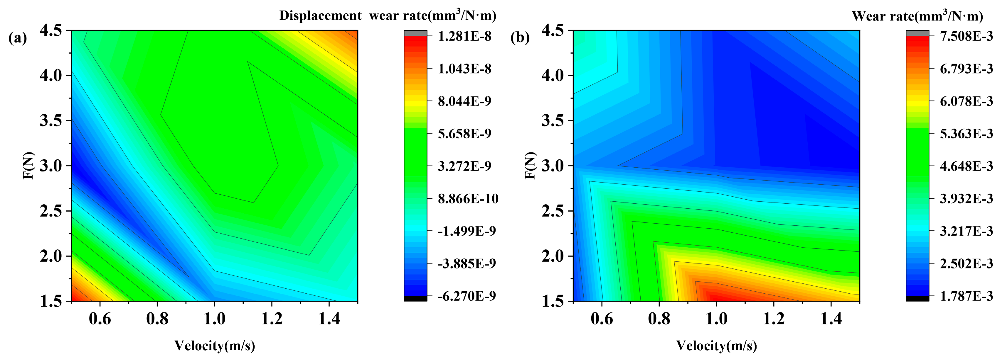
3.1. Friction Coefficients and Wear Rates

Figure 1 shows the friction coefficient of the Ti3SiC2/Cu-45# steel tribo-pair at different velocities and loads. It can be seen from Figure 1 that the friction coefficient ranged from 0.49 to 0.57. Moreover, the friction coefficient of the Ti3SiC2/Cu-45# steel tribo-pair and its volatility were mainly affected by the change in velocity and load at high temperatures. As shown in Figure 1, the friction coefficient decreased with the increase in velocity; that is, the friction coefficient was negatively correlated with velocity.
The volatility of the friction coefficient increased with the increase in velocity; that is, the two were positively correlated as a whole. In addition, the real-time fluctuation range and the periodic fluctuation range of the friction coefficient increased with the increase in load. This indicated that the magnitude and volatility of the friction coefficient were more sensitive to the velocity and load.
It can be seen from Figure 2 that the overall friction coefficient of the tribo-pair tended to increase, but there was still a decrease in the friction coefficient of the local variable region. It was deduced that the tribological performance of the tribo-pair at 800 °C was indeed affected by the velocity and load. The error limits of the friction coefficients were very low when either the velocity, the load, or both variables were small; they increased significantly when both the velocity and load variables increased.
In summary, the friction coefficient was not strictly linearly related to velocity and load. In the case of large values of velocity and load, a low friction coefficient can be obtained by the synergistic effect of the two parameters (see Figure 1f,h). The stability of the friction coefficient can be achieved by the coordination of both velocity and load (see Figure 1e). Therefore, velocity–load, as a whole, caused an increase in the friction coefficient at high temperatures, but the tribological performance can be regulated by coordinating the magnitude of velocity and load.
Figure 3 shows the wear contour of the Ti3SiC2/Cu pin specimen and the 45# steel disc specimen under the influence of velocity and load. From Figure 3a, it can be seen that the wear was higher when both velocity and load were at their minimum or maximum; the wear rate of the tribo-pair was smaller or even negative when a single variable (velocity or load) was larger and the other was smaller. The above law can be described by Equation (1).
a v + b F C ω C - C 0
In Equation (1), a and b are material correlation coefficients; C is a constant; and C0 is the minimum value of C. Equation (1) pointed out that there was a low-wear region under the synergistic influence of velocity and load; that is, the low-wear region can effectively regulate the tribological properties of the tribo-pair. From Figure 3b, it can be seen that the disc specimen was significantly affected by the change in velocity under low loads; with the increase in load, the change in velocity had little effect on the wear of the disc specimen, which remained relatively stable. As seen in Figure 3, the wear rate varied most significantly under loads of 1.5–3 N and velocities of 0.5–1.5 m/s, while the wear rate tended to be stable in the other half of the region.

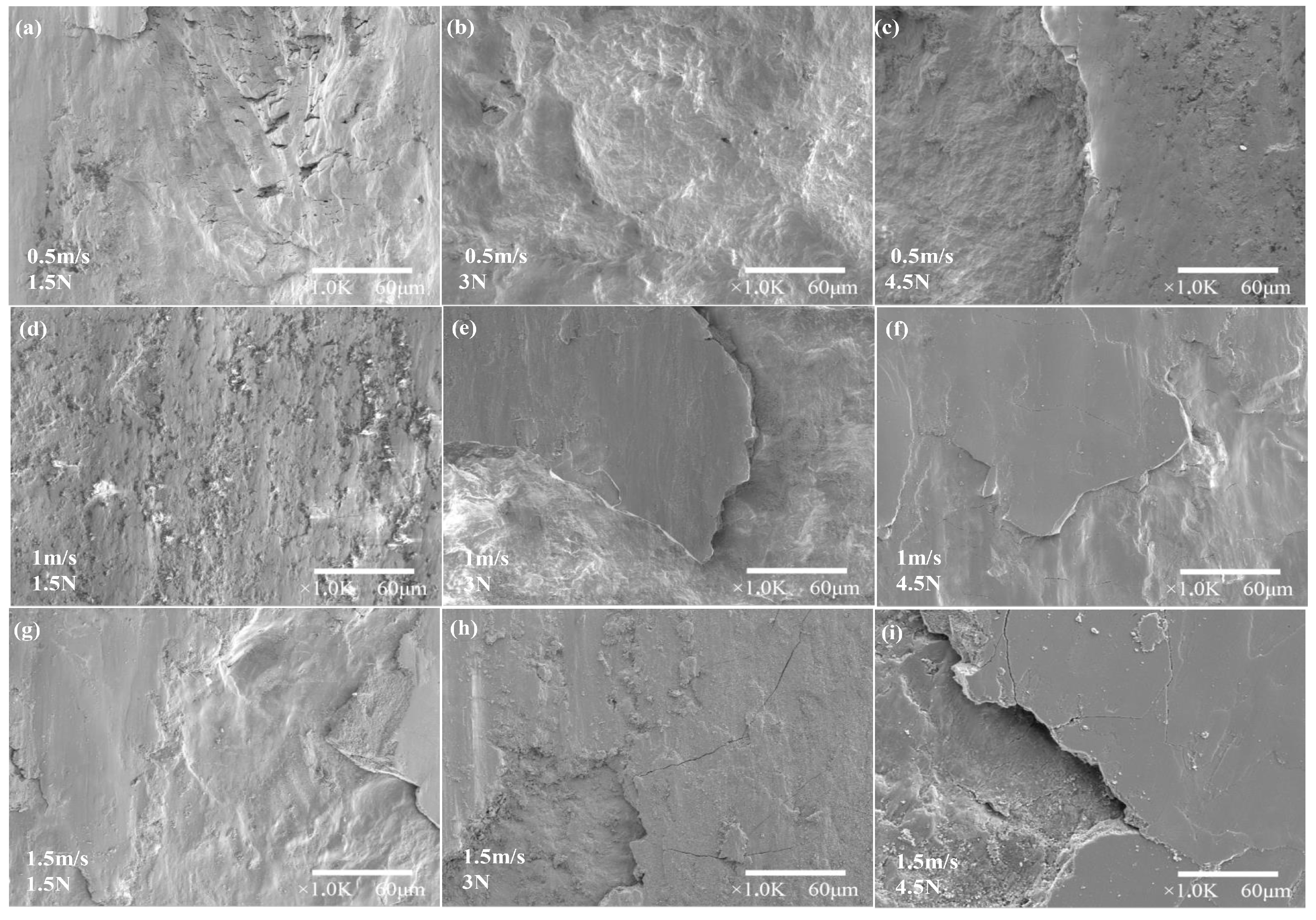
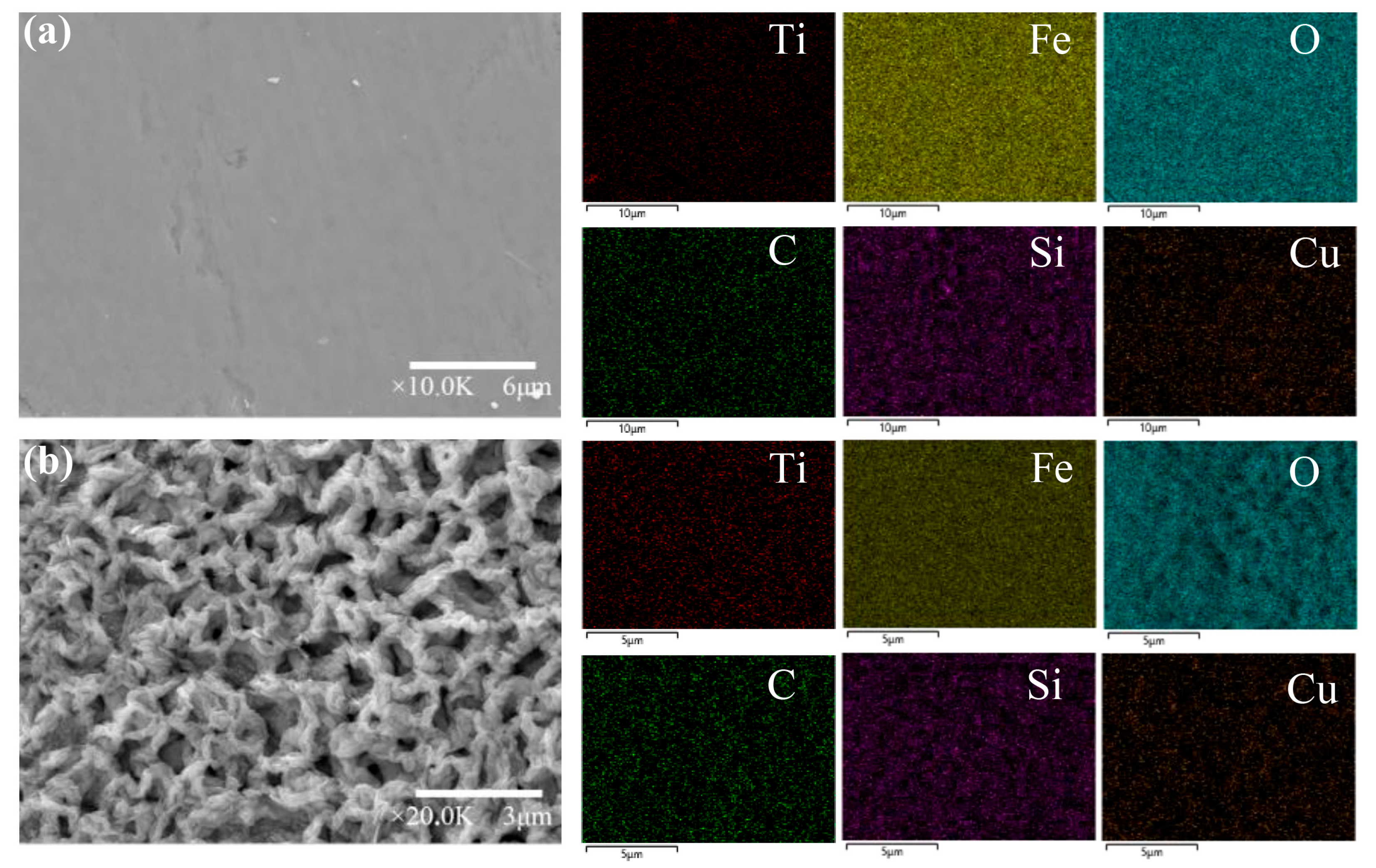
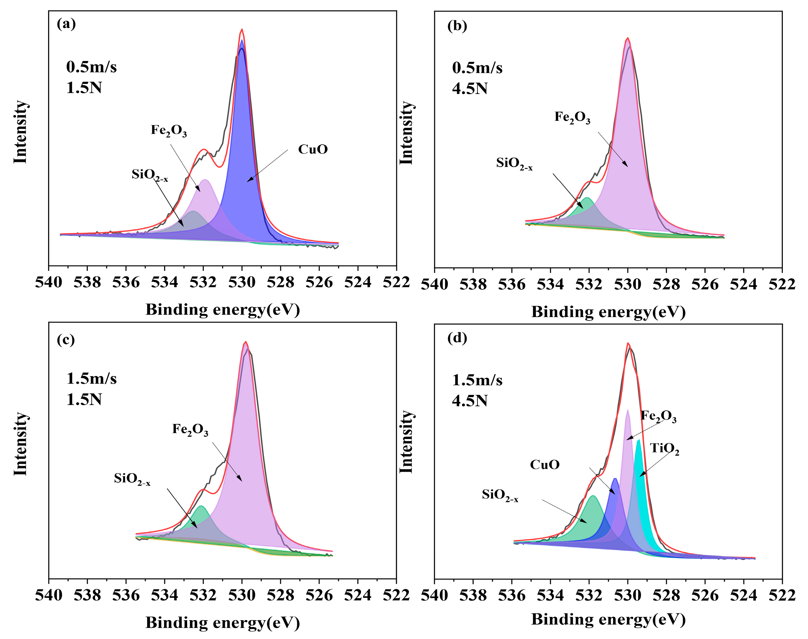
3.2. Morphology and Composition of Worn Surfaces

Figure 4 shows the wear morphology of Ti3SiC2/Cu pin specimens at 800 °C for different velocities (0.5 m/s, 1 m/s, 1.5 m/s) and loads (1.3 N, 3 N, 4.5 N). With the increase in velocity and load, the wear surface was gradually flattened (see Figure 4a,e). This was conducive to the dispersal of the shear force between the friction pairs during the friction process, thus enhancing its tribological performance. As can be seen from Table 2, at 800 °C, under the synergistic effect of velocity and load, the atomic proportion of the O element was the largest among them, while a large amount of the Fe element was observed. This indicated that during the friction process, the oxide layer of the Ti3SiC2/Cu composites mixed with that of the 45# steel disc. The wear surface morphology of the Ti3SiC2/Cu composite included a flat portion, a crushed portion, and a crater-filled portion (see Figure 4c), at which time the wear mechanism was abrasive wear. Under an orthotropy condition of a certain velocity and load, a part of the contact surface of the Ti3SiC2/Cu pin specimen was squeezed, resulting in much higher flatness, while other areas underwent spalling (see Figure 4e), which is also in accordance with Figure 3. When the oxide film on the wear surface ruptured and spalled violently, it resulted in large spalling pits (see Figure 4i), and the spalled oxide film particles became large abrasive grains. At this point, the wear mechanism changed from abrasive wear to a frictional wear mechanism that was dominated by frictional oxidative wear and supplemented by abrasive wear. The wear surface of the pin specimen in the friction process mainly underwent the changes of oxide film formation, compression, fragmentation, exfoliation, and filling on the contact surface. This provided diverse changes in the oxide layer morphology of the Ti3SiC2/Cu-45# steel tribo-pair, which was conducive to improving its lubrication status.
From the morphology of the oxide layer and the elemental surface distribution of the wear surface of 45# steel (disc specimen) (see Figure 5), it can be seen that the oxides at the friction interface of the disc specimen had two main morphologies, i.e., a dense oxide layer (a) and a nascent flocculent oxide layer (b). It can be speculated that when the dense oxide layer was destroyed and peeled off, the metal surface at the original location was exposed and oxidized to form the flocculated oxide. As the friction process proceeded, the nascent oxide layer was extruded or sheared and distributed into the grooves of the friction interface, ultimately becoming a new dense oxide film.
Figure 6 shows the XPS patterns of the wear surface of Ti3SiC2/Cu composites under different velocities and loads at 800 °C. From Figure 6, it can be seen that the Ti element existed in the form of TiO2 only when both velocity and load were at their maximum; the Cu element existed in the form of CuO when both velocity and load were at their minimum or maximum. In contrast, elemental Si and Fe were detected in the forms of oxides, SiO2−X and Fe2O3, respectively, in four conditions. This corresponded to the results of elemental oxygen in Figure 7. In combination with the percentage of the peak areas of the different oxides in Table 3, it was found that the peak areas of the oxides were low or even absent for Ti, Si, and Cu when a single variable was small. When a single variable (velocity or load) changed, the flaking of the oxide film occurred only on the surface of the oxide film, and the substrate material was covered by the oxide film due to the lower degree of flaking. Because the Si element was more active at high temperatures, it was easier to diffuse to the surface of the substrate and cause an oxidation reaction. Additionally, the Cu and Ti elements in the substrate were more stable, and the degree of oxide film peeling was limited by the change in a single variable, so the Cu and Ti elements in the substrate could not be exposed to the outside. However, when both the velocity and load variables reached their maximum, the oxides on the wear surface were composed of SiO2−x, Fe2O3, CuO, and TiO2. Moreover, the peak areas in Table 3 show that the oxides of Fe elements were greatly reduced, while the oxides of Ti, Si, and Cu increased. When the bivariate variables were simultaneously increased, the material was tightly squeezed and violently sheared at the same time, and a significant exfoliation state occurred. The fragmentation of the oxide film increased, and the size of the exfoliated particles was larger. The matrix of the Ti3SiC2/Cu composite inside was susceptible to oxidation, and the formation of a new oxide film led to an increase in the oxide species and elemental content.

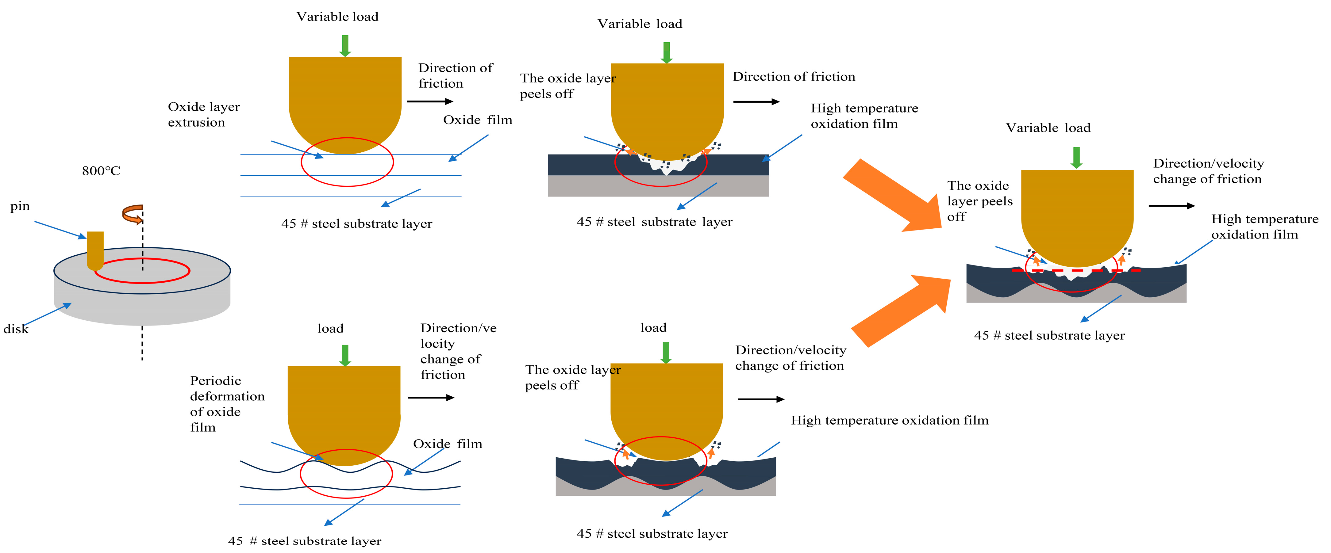
3.3. Friction Mechanism

The friction and wear of the Ti3SiC2/Cu-45 steel friction mating pair were affected by the synergistic effect of velocity and load at 800 °C. With the increase in velocity and load, the wear mechanism transformed from abrasive wear to frictional oxidation wear. When the two variables reached their maximum, the wear mechanism was composed of the main wear mechanism of frictional oxidation wear and the supplementary wear mechanism of abrasive wear (Figure 8). In the friction process, frictional oxidation was the main influencing factor for the formation of the oxide film.
The increase in velocity led to a gradual increase in the flaking amount of the oxide film. The thicker the oxide layer, the greater the amount of flaking. Moreover, the more complex the frictional morphology, the higher the friction coefficient. When the oxide film became thinner after peeling, the frictional morphology became flatter, and the friction coefficient became smaller. These led to an increase in the fluctuation of the friction coefficient, and they showed an overall cyclic fluctuation. At the same time, as the velocity increased, the frictional work increased. Additionally, the temperature of the contact surface increased [21], leading to an increase in the generation rate of oxide films on the surface. During the process of friction, the broken area of the oxide film can quickly generate new oxide films.
With the increase in load, the densification of the oxide film on the surface of the composites increased, resulting in an increase in the mechanical stability of the oxide film. At this time, the effect of the impact vibration caused by the load on the spalling of the oxide film tended to be stable. When the load continued to increase, part of the oxide film spalled, and the newly formed oxide layer under the spalled oxide film was squeezed into the dense oxide film [22]. Due to the difference in mechanical properties between the newly formed oxide and the dense oxide film, the changes in the local friction coefficient during the friction process were significant, and the transient fluctuations overall increased in amplitude.
Under the synergistic effect of velocity and load, the oxide film first showed a close-packed state, resulting in a decrease in the friction coefficient and an increase in the flatness of the friction surface. When the velocity and load increased further, part of the oxide film on the friction surface ruptured or even spalled off to produce abrasive particles, resulting in an increase in the fluctuation of the friction coefficient and the appearance of pits in the spalling area. When velocity and load reached their maximum values, the degree of exfoliation in the exfoliated area increased. Additionally, the exposure of the substrate inside led to its oxidation, and a large number of exfoliated pits appeared on the friction surface. The large abrasive particles exfoliated during friction increased the fluctuation of the friction coefficient. On the other hand, the surface of the non-spalled areas was flatter due to the effect of the load.

4. Conclusions

The tribological properties of Ti3SiC2/Cu composites were influenced by oxide formation and depletion, which were adjusted by a synergistic change in velocity and load. The influence of velocity came from the removal and formation of oxides, while the main influence of load came from the extrusion and crushing of the oxide layer. The single variable of velocity–load mainly caused the flake and flattening of the oxide film, which included the elevated frictional work and the extrusion of oxide products. Thus, they affected the friction coefficient of the composites. The velocity–load bivariate variable increased the generation rate of the oxide film. Additionally, it increased the quantity of flaking particles in the oxide film, changed the phase composition of the oxides, and caused intense micro-impacts. Therefore, larger transient and cyclic fluctuations were shown in the friction coefficient. In the friction process, the abrasive wear was gradually transformed into frictional oxidative wear. Eventually, the wear mechanism was composed of mainly frictional oxidative wear and abrasive wear as a supplement.

Author Contributions

Conceptualization, R.Z. and B.L.; Data curation, B.C. and B.L.; Formal analysis, R.Z., B.L., and B.C.; Investigation, R.Z., F.L., and B.L.; Methodology, R.Z. and B.L.; Writing—original draft, R.Z., B.L., and B.C.; Writing—review and editing, R.Z., F.L., and B.L. All authors have read and agreed to the published version of the manuscript.

Funding

This research received no external funding.

Institutional Review Board Statement

There are no human subjects in this article and ethical approval is not applicable. Statement of Human and Animal Rights: This article does not include any studies involving humans or animals.

Informed Consent Statement

There are no human subjects in this article and informed consent is not applicable.

Data Availability Statement

The original contributions presented in the study are included in the article, further inquiries can be directed to the corresponding authors.

Acknowledgments

The author acknowledges the financial support from the Open Project of the State Key Laboratory of Solid Lubrication, Chinese Academy of Sciences (LSL-2115).

Conflicts of Interest

All authors of this research paper have directly participated in the planning, execution, or analysis of the study. All authors of this paper have read and approved the final version submitted. The contents of this manuscript have not been copyrighted or published previously. The contents of this manuscript are not under consideration for publication elsewhere. The contents of this manuscript will not be copyrighted, submitted, or published elsewhere while acceptance of the manuscript is under consideration. There are no directly related manuscripts or abstracts, published or unpublished, by any author(s) of this paper.

References

  1. Ren, X.; Zou, H.; Diao, Q.; Wang, C.; Wang, Y.; Li, H.; Sui, T.; Lin, B.; Yan, S. Surface modification technologies for enhancing the tribological properties of cemented carbides: A review. Tribol. Int. 2023, 180, 108257. [Google Scholar] [CrossRef]
  2. Xue, Y.; Ye, Y.; Guo, J.; Qian, W.; Jin, Z.; Dai, F.; Hua, Y.; Cai, J. Microstructural evolution and high-temperature oxidation resistance of NiCoCrAlYSiHf coatings after surface thermal modification with millisecond laser. Appl. Surf. Sci. 2024, 644, 158697. [Google Scholar] [CrossRef]
  3. Ye, W.; Shi, Y.; Zhou, Q.; Xie, M.; Wang, H.; Bou-Saïd, B.; Liu, W. Recent advances in self-lubricating metal matrix nanocomposites reinforced by carbonous materials: A review. Nano Mater. Sci. 2024, in press. [Google Scholar] [CrossRef]
  4. Silvestroni, L.; Melandri, C.; Gonzalez-Julian, J. Exploring processing, reactivity and performance of novel MAX phase/ultra-high temperature ceramic composites: The case study of Ti3SiC2. J. Eur. Ceram. Soc. 2021, 41, 6064–6069. [Google Scholar] [CrossRef]
  5. Singh, J.; Wani, M.F. Fretting wear of spark plasma sintered Ti3SiC2/GNP ceramic composite against Si3N4. Ceram. Int. 2021, 47, 5648–5655. [Google Scholar] [CrossRef]
  6. Wang, J.; Ge, Y.; Ma, Y.; Qu, C.; Li, X.; Qu, S. Synergistic effect of the combined surface modification technology on rotational bending fatigue of low carbon alloy steel. Vacuum 2023, 212, 111993. [Google Scholar] [CrossRef]
  7. Azina, C.; Poll, M.; Holzapfel, D.M.; Tailleur, E.; Zuber, A.; Dubois, S.; Eklund, P.; Gonzalez-Julian, J. Microstructural and compositional design of Cr2AlC MAX phases and their impact on oxidation resistance. J. Eur. Ceram. Soc. 2024, 44, 4895–4904. [Google Scholar] [CrossRef]
  8. Vatanpour, V.; Mehrabani, S.A.N.; Dehqan, A.; Arefi-Oskoui, S.; Orooji, Y.; Khataee, A.; Koyuncu, I. Performance improvement of polyethersulfone membranes with Ti3AlCN MAX phase in the treatment of organic and inorganic pollutants. Chemosphere 2024, 362, 142583. [Google Scholar] [CrossRef] [PubMed]
  9. Cygan, T.; Wozniak, J.; Broniszewski, K.; Kulikowski, K.; Moszczyńska, D.; Adamczyk-Cieślak, B.; Kurkowska, M.; Olszyna, A. Analysis of microstructure and mechanical properties of alumina composites reinforced with Ti2AlN MAX phases. Int. J. Refract. Met. Hard Mater. 2024, 122, 106725. [Google Scholar] [CrossRef]
  10. Wei, X.; Li, L.; Liu, F.; Fan, L.; Wu, Y. Synthesis, microstructure, and mechanical properties of MAX phase Ti2GaC ceramics with V doping. Ceram. Int. 2024, 50, 15806–15820. [Google Scholar] [CrossRef]
  11. Zhang, J.; Liu, W.; Jin, Y.; Wu, S.; Hu, T.; Li, Y.; Xiao, X. Study of the interfacial reaction between Ti3SiC2 particles and Al matrix. J. Alloys Compd. 2018, 738, 1–9. [Google Scholar] [CrossRef]
  12. Wang, L.; Tong, Y.G.; Zhou, C.; Li, Y.J.; Liu, J.; Cai, Z.H.; Wang, H.D.; Hu, Y.L. Self-lubricating Ti3SiC2 strengthening Cu composites with electrical conductivity and wear resistance trade off. Tribol. Int. 2023, 187, 108724. [Google Scholar] [CrossRef]
  13. Yang, Z.; Xu, J.; Qian, Y.; Liu, H.; Zuo, J.; Ma, K.; Li, M. Electrical conductivities and mechanical properties of Ti3SiC2 reinforced Cu-based composites prepared by cold spray. J. Alloys Compd. 2023, 946, 169473. [Google Scholar] [CrossRef]
  14. Zhang, X.; Liang, Y.; Lei, Q.; Xiao, S.; Jiang, Y. Effect of Ti3SiC2 replacing graphite on the microstructure and properties of Cu-Sn matrix composites. Tribol. Int. 2024, 194, 109540. [Google Scholar] [CrossRef]
  15. Shu, R.; Jiang, X.; Liu, W.; Shao, Z.; Song, T.; Luo, Z. Synergetic effect of nano-carbon and HBN on microstructure and mechanical properties of Cu/Ti3SiC2/C nanocomposites. Mater. Sci. Eng. A 2019, 755, 128–137. [Google Scholar] [CrossRef]
  16. Chen, B.; Zhang, R.; Liu, F.Y.; Wu, C.L.; Zhang, H.M.; Sun, M.; Tulugan, K. Effect of full melt temperature sintering and semi-melt heat preservation sintering on microstructure and mechanical properties of Ti3SiC2/Cu composites. Mater. Res. Express 2024, 11, 13. [Google Scholar] [CrossRef]
  17. Magnus, C. Sliding wear of MAX phase composites Ti3SiC2–TiC and Ti3SiC2–Ti2AlC at 400 °C and the influence of counterface material (steel, Al2O3, and Si3N4) on wear behaviour. Wear 2023, 516–517, 204588. [Google Scholar] [CrossRef]
  18. Wang, Q.; Peng, Y.; Jiang, W.; Xu, H.; Hai, W.; Shao, Q.; Li, A. Effect of high temperature oxidation on mechanical and electromagnetic interference shielding effectiveness of Ti3SiC2 modified SiCf/BN/SiBCN composites. Ceram. Int. 2024, 50, 20167–20175. [Google Scholar] [CrossRef]
  19. Gou, R.; Luo, X. Friction behavior and wear mechanism of the PDC-CR in comparison with different friction pairs at high temperatures. Ceram. Int. 2024, 50, 8132–8140. [Google Scholar] [CrossRef]
  20. Liu, G.-L.; Sun, X.-X.; Cai, Y.-Y.; Li, Z.-Q.; Xu, F.-H.; Cao, Y.-H.; Liu, H.-X.; Zhou, J.-Z.; Cheng, X.-N. High-temperature dry sliding friction and wear behavior of Ni60A coating on the 20CrNiMo alloy surface treated by laser shock peening and its bonding zone. J. Mater. Res. Technol. 2024, 29, 2902–2911. [Google Scholar] [CrossRef]
  21. Meng, X.; Cui, Z.; Huang, L.; Xia, C.; Lei, Q. Effects of loads and speeds on friction and wear properties of Cu–Ti alloys processed by combination aging treatments. J. Mater. Res. Technol. 2023, 26, 948–960. [Google Scholar] [CrossRef]
  22. Kandasamy, K.P.J. Effect of load and sliding velocity on wear behaviour of magnesium AZ91D composites reinforced with Ca2SiO4 at ambient temperature. Tribol. Int. 2024, 192, 109314. [Google Scholar]
Figure 1. Variation in friction coefficient with time for the Ti3SiC2/Cu-45# steel tribo-pair under the synergistic effect of velocity (0.5–1.5 m/s) and load (1.5–4.5 N): (a) 0.5 m/s, 1.5 N; (b) 0.5 m/s, 3 N; (c) 0.5 m/s, 4.5 N; (d) 1 m/s, 1.5 N; (e) 1 m/s, 3 N; (f) 1 m/s, 4.5 N; (g) 1.5 m/s, 1.5 N; (h) 1.5 m/s, 3 N; (i) 1.5 m/s, 4.5 N.
Lubricants 12 00265 g001
Figure 2. Contour plots of friction coefficient of the Ti3SiC2/Cu-45# steel tribo-pair under the synergistic effect of velocity (0.5–1.5 m/s) and load (1.5–4.5 N).
Lubricants 12 00265 g002
Figure 3. Contour plots of wear rates of Ti3SiC2/Cu (a) and 45# steel (b) under the synergistic effect of velocity (0.5–1.5 m/s) and load (1.5–4.5 N).
Lubricants 12 00265 g003
Figure 4. Wear morphology of the Ti3SiC2/Cu pin under the synergistic effect of velocity (0.5–1.5 m/s) and load (1.5–4.5 N) at 800 °C: (a) 0.5 m/s, 1.5 N; (b) 0.5 m/s, 3 N; (c) 0.5 m/s, 4.5 N; (d) 1 m/s, 1.5 N; (e) 1 m/s, 3 N; (f) 1 m/s, 4.5 N; (g) 1.5 m/s, 1.5 N; (h) 1.5 m/s, 3 N; (i) 1.5 m/s, 4.5 N.
Lubricants 12 00265 g004
Figure 5. Morphology and surface distribution of (a) unworn and (b) worn oxidized layers on the frictional interface of 45# steel.
Lubricants 12 00265 g005
Figure 6. XPS spectra of the worn surface of the Ti3SiC2/Cu pin under the synergistic effect of velocity (0.5–1.5 m/s) and load (1.5–4.5 N) at 800 °C.
Lubricants 12 00265 g006
Figure 7. Fine spectra of O1s on the worn surface of Ti3SiC2/Cu pin under the synergistic effect of velocity (0.5–1.5 m/s) and load (1.5–4.5 N) at 800 °C: (a) 0.5 m/s, 1.5 N; (b) 0.5 m/s, 4.5 N; (c) 1.5 m/s, 1.5 N; (d) 1.5 m/s, 4.5 N.
Lubricants 12 00265 g007
Figure 8. Friction and wear mechanism of the Ti3SiC2/Cu-45# steel tribo-pair.
Lubricants 12 00265 g008
Table 1. Parameters of velocity and load and number of friction and wear experiments.
Velocity/m·s−10.511.5
No.
Load/N
1.5adg
3beh
4.5cfi
Table 2. Atomic percentage of the worn surface of the Ti3SiC2/Cu bolus specimen.
PositionSampleVelocity (m/s)Load (g)Atomic Percentage
Figure 4apin0.51507.65% Ti, 0.56% Si, 5.69% C, 0.55% Cu, 31.88% Fe, 53.67% O
Figure 4bpin0.53000.33% Ti, 0.29% Si, 7.2% C, 0.08% Cu, 38.22% Fe, 53.88% O
Figure 4cpin0.54500.46% Ti, 0.29% Si, 9.65% C, 0.55% Cu, 33.19% Fe, 55.85% O
Figure 4dpin11500.21% Ti, 0.23% Si, 18.52% C, 0.75% Cu, 25.91% Fe, 54.38% O
Figure 4epin13000.18% Ti, 0.26% Si, 7.35% C, 0% Cu, 38.65% Fe, 53.56% O
Figure 4fpin14500.29% Ti, 0.34% Si, 5.65% C, 0.59% Cu, 43.1% Fe, 50.03% O
Figure 4gpin1.51501.49% Ti, 0.59% Si, 8.31% C, 1.28% Cu, 30.83% Fe, 57.5% O
Figure 4hpin1.53000.52% Ti, 0.23% Si, 7.25% C, 0.4% Cu, 39.64% Fe, 51.97% O
Figure 4ipin1.54501.35% Ti, 0.53% Si, 8.45% C, 1.09% Cu, 43.89% Fe, 44.69% O
Table 3. Relative peak area of O1s for oxides on the surface of the Ti3SiC2/Cu pin.
OxideRelative Peak Area (%)
Oxides of TiOxides of SiOxides of CuOxides of FeOxides of TiOxides of SiOxides of CuOxides of Fe
a/SiO2−xCuOFe2O3/13.427.659.0
b/SiO2−x/Fe2O3/11.7/88.3
c/SiO2−x/Fe2O3/13.5/86.5
dTiO2SiO2−xCuOFe2O327.219.420.233.2
Disclaimer/Publisher’s Note: The statements, opinions and data contained in all publications are solely those of the individual author(s) and contributor(s) and not of MDPI and/or the editor(s). MDPI and/or the editor(s) disclaim responsibility for any injury to people or property resulting from any ideas, methods, instructions or products referred to in the content.

