Article

Effect of Electroplastic-Assisted Grinding on Surface Quality of Ductile Iron

1
College of Mechanical Engineering and Automation, Liaoning University of Technology, Jinzhou 121001, China
2
School of Mechanical and Automotive Engineering, Qingdao University of Technology, Qingdao 266520, China
3
School of Mechanical and Traffic Engineering, Ordos Institute of Technology, Ordos Avenue East, Ordos 017000, China
4
School of Mechanical Engineering, Jiangsu University, Zhenjiang 212013, China
5
Tianjin TANHAS Technol Co., Ltd., Tianjin 301000, China
6
The First Machinery Group, Inner Mongolia Ruite Precision Mould Co., Ltd., Baotou 014030, China
7
Department of Mechanics, Inner Mongolia University of Technology, Hohhot 010051, China
*
Author to whom correspondence should be addressed.
Lubricants 2024, 12(8), 266; https://doi.org/10.3390/lubricants12080266 (registering DOI)
Submission received: 25 June 2024 / Revised: 22 July 2024 / Accepted: 24 July 2024 / Published: 26 July 2024
(This article belongs to the Special Issue Tribological Properties of Biolubricants)

Abstract

:
Ductile iron is a heterogeneous material. The presence of spherical graphite and a hard and brittle structure makes the surface of the workpiece easily form pits and crack defects under harsh grinding conditions, which seriously affects the service life and service performance of the workpiece. The new assisted grinding process based on the electroplastic effect is expected to avoid the surface defects of ductile iron. By comparing the surface roughness and microstructure of conventional grinding and electroplastic-assisted grinding, the superiority of electroplastic-assisted grinding surface quality is confirmed. Further discussion is presented on the impact of grinding parameters on the workpiece’s surface quality under the same electrical parameters. The results show that the sensitivity of surface roughness to grinding parameters from strong to weak is grinding wheel speed, feed speed and grinding depth. The optimal combination of grinding parameters is determined as a grinding wheel speed of 30 m/s, a feed speed of 0.5 m/min and a grinding depth of 10 μm.

1. Introduction

In ductile iron, flake graphite in the metal matrix is modified into a spherical shape by spheroidization and inoculation treatment. The uniform distribution of spherical graphite can greatly reduce the cracking of graphite on the matrix material, which is beneficial to alleviate the stress concentration phenomenon during processing to improve the mechanical properties of ductile iron [1,2]. Because of this, ductile iron is widely used in the manufacture of various power machinery such as crankshafts, gears, hydraulic cylinder bodies, and complex bearing parts [3,4,5]. However, the excellent strength, hardness, and wear resistance of ductile iron also bring difficulties and challenges to its high-quality grinding. As a typical heterogeneous metal material, there are significant performance differences between graphite and the metallic matrix. In terms of metal processing, the material removal uniformity is poor, the surface roughness is high, and it is easy to adversely affect the surface processing quality [6,7]. In addition, the non-uniform stress at the interface of the graphite–metallic matrix also easily aggravates the initiation and propagation of surface cracks, which has a potential impact on the service performance and life of parts.
Electroplastic-assisted machining (EPAM) is a new processing technology that introduces an electric field in machining to reduce the deformation resistance of materials and improve the machinability of materials by using the electroplastic effect [8,9]. At present, the mechanism of the electroplastic effect has not been fully understood. The existing research shows that electroplasticity is the result of the coupling of various physical effects under an applied action field and can be divided into thermal and athermal effects. Thermal heating effects occur when a high-energy current acts on the metal workpiece and generates Joule heating to the inherent resistance of the metal. The deformation capability of metal flow is augmented, thereby enhancing the plasticity of the workpiece [10,11]. However, the improvement in the machinability of the workpiece cannot be simply explained by the thermal effect. Mai et al. [12] carried out electroplastic-assisted 316L tensile testing and found that the thermal effect caused by electroplasticity is one of the favorable factors in reducing flow stress. At the same time, compared with the workpiece under the same Joule heat, flow stress also decreases with an increase in current density. High energy current reduces the activation energy of dislocations on the metal surface, causing a favorable transformation of the microstructure and reducing deformation resistance [13,14,15]. Athermal effects include electron wind effect, depinning effect, magnetostrictive effect, skin effect, and pinch effect [16]. High dislocation densities in the metal cause obstacles to plastic deformation. The electron wind effect caused by electroplasticity activates drift electrons, which can effectively promote dislocation slip and reduce the degree of accumulation. Xiang et al. [17] applied a pulse current of 10 A/mm2 to a quenched low-carbon steel with initial residual stress and found that the residual stress was significantly reduced. Furthermore, Fan et al. [18] integrated the results of simulation and experimentation and concluded that pulse currents can enhance dislocation accumulation by promoting the depinning movement of dislocations in addition to the electron wind effect. In contrast, the effects of skin effect, pinch effect and magnetostrictive effect on plasticity enhancement are much smaller and are limited by sample size and material type [19,20]. Benefiting from the combined effect of thermal and athermal effects on the plasticity of materials, EPAM technology has been regarded as an advanced method in material processing applications [21,22,23,24].
At present, EPAM has been widely used in metal plastic forming. Troitskiy et al. [25] demonstrated that pulsed current can significantly diminish the drawing force needed for forming and induce discernible changes in the microstructure of the metal. This is beneficial to improve the plasticity of copper wire and reduce the number of defects. Qian et al. [26] carried out a comparative study on the electroplastic rolling performance and conventional rolling performance of low carbon martensitic steel under different deformation. The results show that electrically assisted rolling can not only effectively improve the elongation of the workpiece, but also regulate the micro-texture and mechanical properties of the metal samples. In view of the excellent characteristics of electroplastic effects in the field of plastic forming, scholars have tried to apply it to the field of cutting and made some progress. Wang et al. [27] studied the turning performance of 304 stainless steel under an electric pulse. The results show that the application of an electric pulse in the turning process can improve the plastic deformation ability of the cutting area, thereby reducing the main cutting force and surface roughness.
It has been confirmed by many scholars that the applied electric field can significantly enhance the cutting deformation ability of metal materials and further improve the machinability of materials [28,29,30]. However, there is still a lack of relevant research on grinding conditions at high temperature, high speed, and high pressure. As one of the finishing processes, grinding has a decisive influence on the surface roughness, surface morphology, and surface defects of the workpiece. There are several difficulties in grinding ductile iron due to the performance disparity between graphite and metal matrix. Studies have shown that the morphology and distribution of graphite have a great influence on grinding quality [31]. Spherical graphite with small size and uniform distribution can reduce the performance difference between the phases, which is beneficial for improving the stability of the grinding process and improving the surface quality of the workpiece [32]. In view of the poor grinding performance of ductile iron, it is of great practical significance to carry out electroplastic-assisted grinding research to improve workpiece quality.
In grinding processes, the most complex aspect of controlling surface quality is to ensure the stability of material removal. Under harsh grinding conditions, the surface of the workpiece is prone to pits and cracking defects. The addition of pulsed current is anticipated to mitigate surface defects during grinding, thereby enhancing the surface quality of the workpiece. For assessing the grinding surface, surface roughness and morphology characteristics are chosen as evaluation criteria. Under consistent electrical parameters, this study explores the impact of grinding wheel speed, feed rate, and grinding depth on the surface quality of ductile iron workpieces. It is proved that the electroplastic effect feasibly improves the surface quality of grinding.

2. Materials and Methods
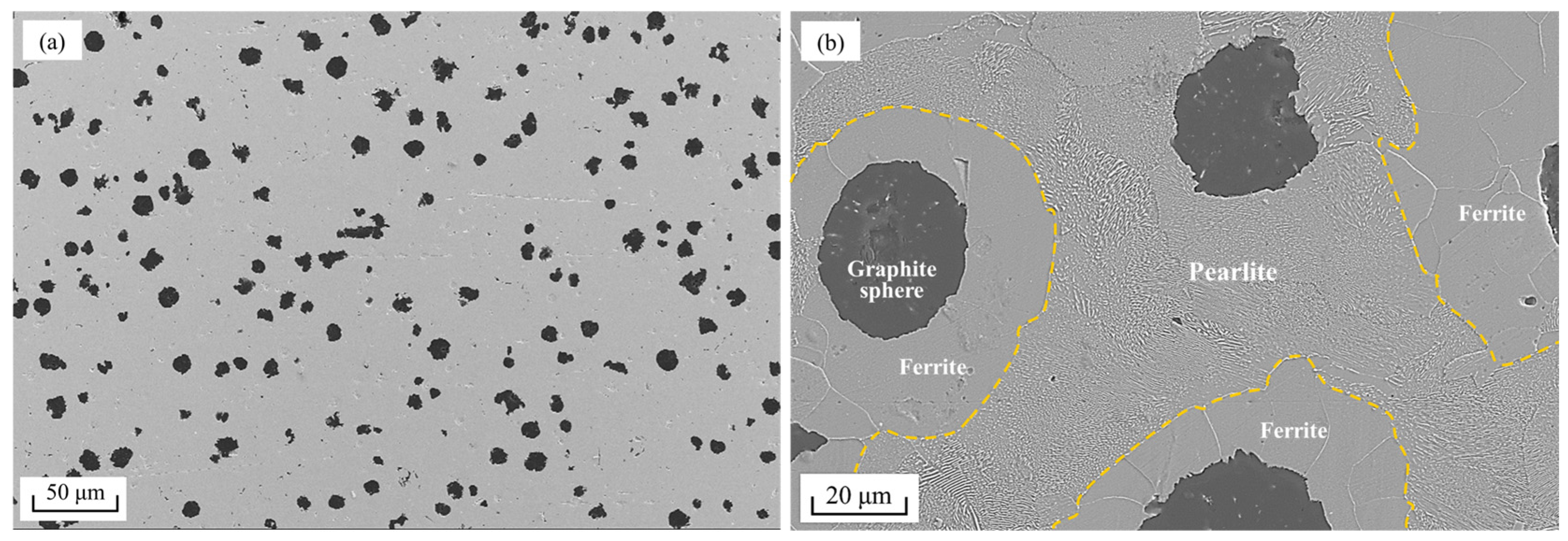
2.1. Materials

The material used in the experiment is QT500-7(GB/T 1348-2019) ductile iron, which has good strength and toughness, good wear resistance, and excellent comprehensive mechanical properties. The graphite morphology and distribution of QT500-7 ductile iron samples are shown in Figure 1a,b shows the matrix microstructure (ferrite and pearlite) of the sample.
The standard chemical composition and mechanical properties of ductile iron according to standard (GB/T 1348-2019) are shown in Table 1 and Table 2.

2.2. Experimental Setup

The electroplastic-assisted grinding system is shown in Figure 2, which is mainly composed of small plane grinding machine table (self-made) (Figure 2a), pulse power supply (1000A/12V, Guangzhou Jiantong Automation Equipment Co., Ltd., Guangzhou, China) (Figure 2e), and pneumatic micro-lubrication pump (KS-2106B, Shanghai Jinzhao Energy Saving Technology Co., Ltd., Shanghai, China) (Figure 2b). Figure 2f is the layout of electroplastic-assisted grinding experimental equipment. The power supply outputs square wave DC pulse electricity, which is connected to both ends of the ductile iron workpiece through a conductive line. The pulse direction is consistent with the grinding direction. Insulation fixtures are used to separate the workpiece from the grinding machine table and insulation gaskets are set at the connection between the table and the machine tool to ensure the safety of the experiment. The grinding machine utilizes a resin-bonded cubic boron nitride (CBN) grinding wheel measuring 180 mm in diameter and 13 mm in thickness, with a grit size of 120#.
Pneumatic micro-lubrication was used in the experiment, and the pressure was 0.25 MPa. In order to consider the safety in the electrically assisted processing environment, the synthetic grease lubricating coolant (KS-1132, Shanghai Jinzhao Energy Saving Technology Co., Ltd., Shanghai, China) was selected to balance good insulation and lubrication effects.
A K-type anti-interference thermocouple is embedded 1 mm below the surface to be processed, and the sampling rate is 100,000 samples/s. A Smacq USB-1252A data acquisition card (Smacq, Beijing, China) is used to collect the surface temperature, and the surface Joule heat temperature rise caused by the skin effect is verified to improve the plasticity of the workpiece.
After the grinding is completed, the surface roughness and surface morphology of the grinding surface are detected by a LEXT OLS5000 laser confocal microscope (Olympus Corporation, Tokyo, Japan) (Figure 2d) and Sigma300 field emission scanning electron microscope (Zeiss, Jena, Germany) (Figure 2c), which is used to analyze the variation law of grinding parameters.

2.3. Experimental Design

Firstly, the conventional grinding experiment of ductile iron was carried out to compare the variation in surface roughness and surface morphology to electroplastic-assisted grinding. A Taguchi L9(34) orthogonal array is further selected to obtain 9 groups of experimental schemes, and the influence of grinding parameter coupling on the grinding surface quality of ductile iron in an electroplastic-assisted process is analyzed. The orthogonal test factors and levels are shown in Table 3.
The process parameters are composed of electrical parameters and grinding parameters. The grinding quality of the workpiece surface is greatly affected by the size of the pulse current, pulse frequency, and duty cycle. Based on previous electrical parameter optimization experiments, 600A pulse current, 200Hz pulse frequency, and 50% duty ratio are chosen to optimize surface quality and ensure experiment safety [33]. Grinding parameters considered include grinding wheel speed, feed speed, and grinding depth. The range of specific parameters is shown in Table 4.

3. Results and Discussion

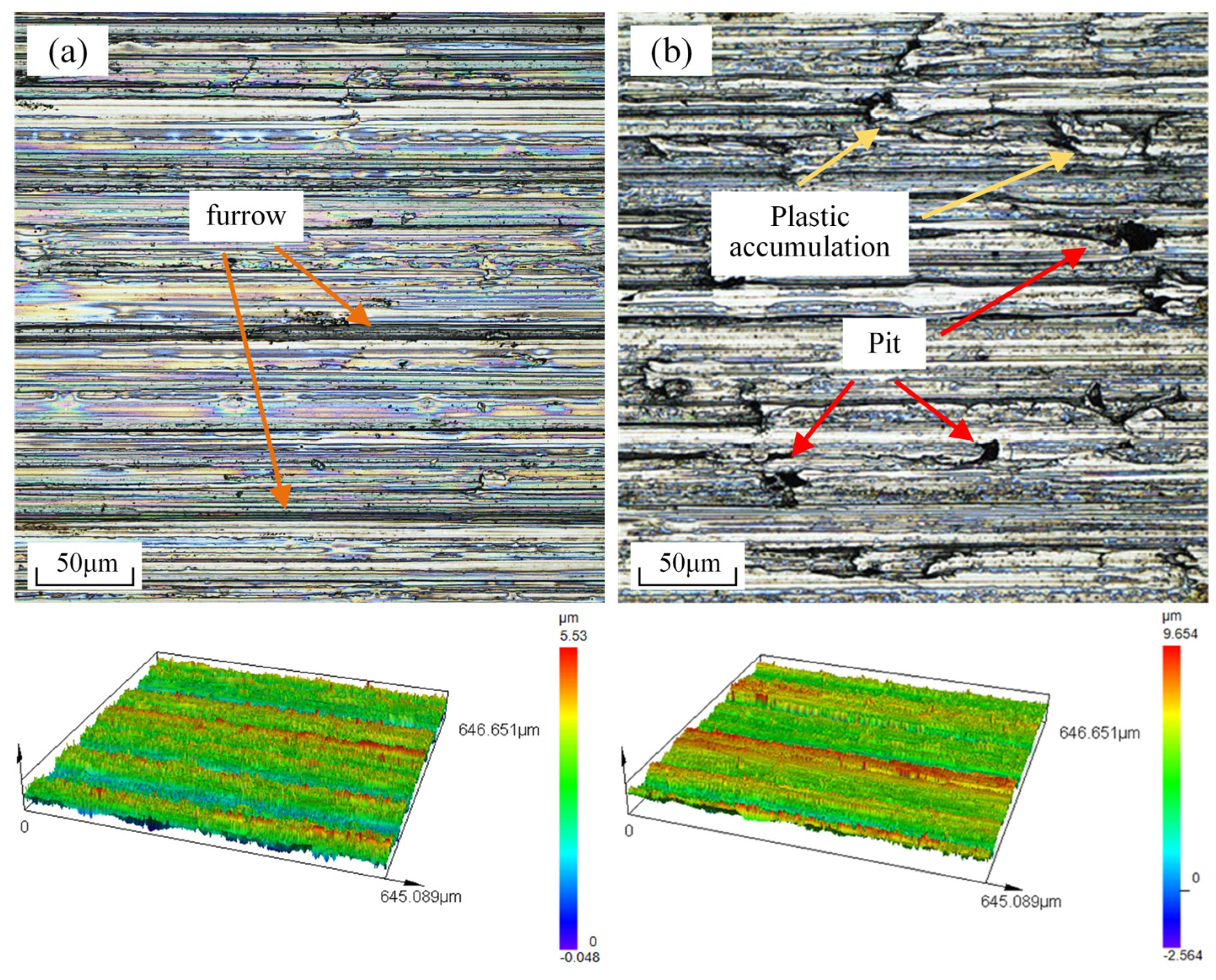
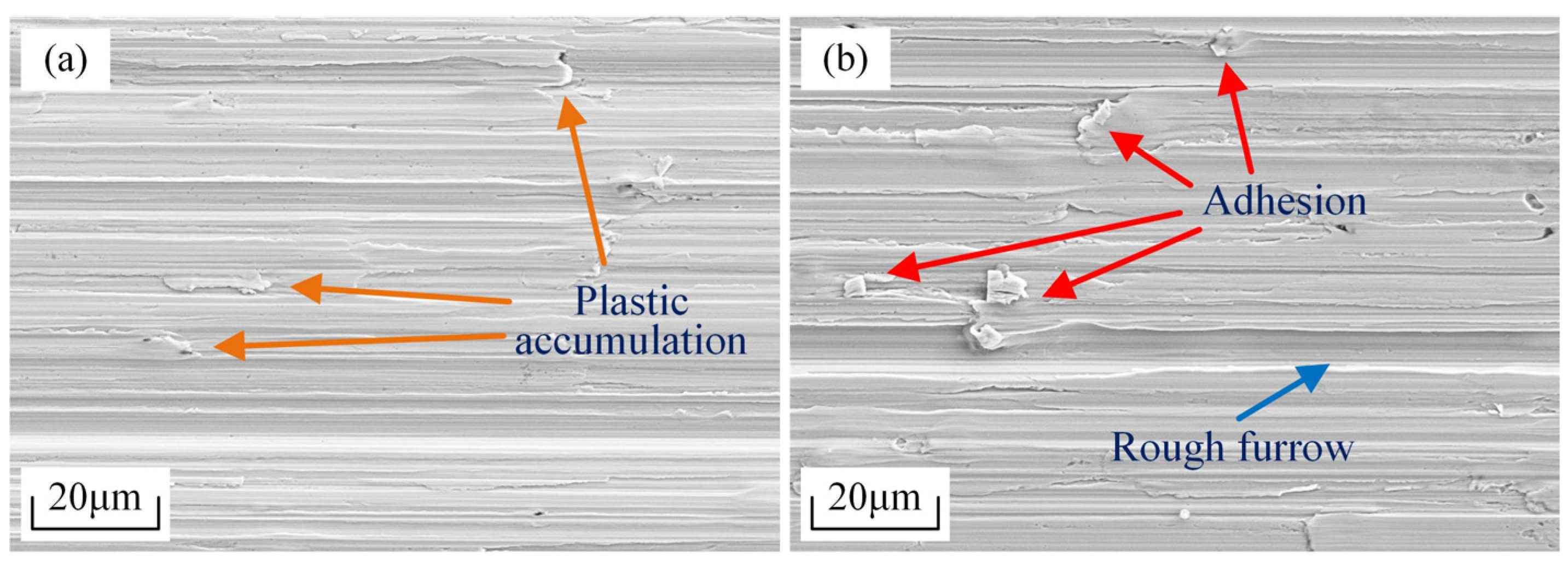
3.1. Surface Quality Optimization Verification of Electroplastic-Assisted Grinding

Surface roughness is an important index to evaluate the quality of the grinding surface. The surface roughness Sa contains more comprehensive surface characteristics, so it is more suitable for evaluating the surface quality of the workpiece than the line roughness Ra [34,35]. Surface roughness Sa measurement via laser confocal microscope is conducted in accordance with ISO 25178 international standards for non-contact methods. The roughness values of the corresponding samples were obtained from the surface morphology measured by the laser confocal microscope. Taking the conventional grinding experiment as the control group, the results of the surface roughness value Sa measured by the laser confocal microscope are shown in Figure 3. The comparative experiment was carried out under the condition of a grinding wheel speed of 30 m/s, feed speed of 1 m/min and grinding depth of 20 μm. Five different regions (800 × 800 μm) of ductile iron workpiece after conventional grinding were selected and the surface roughness Sa was counted. The average surface roughness value was determined to be 1.350 ± 0.14 μm. In contrast, the average surface roughness Sa of the electroplastic-assisted grinding workpiece is 0.878 ± 0.11 μm, which proves that the introduction of pulse current can significantly improve the grinding surface quality of ductile iron.
Figure 4 shows the surface morphology of conventional grinding and electroplastic-assisted grinding. For conventional grinding, there are usually prominent crack defects and pits formed by brittle peeling of materials on the surface of the workpiece. As shown in Figure 4a,c, in view of the difference in hardness of the workpiece caused by the spherical graphite, the surface brittle removal points show a regional aggregation distribution. Under the pressure and cutting of the abrasive particles, the graphite sphere at the center is separated from the matrix material, thereby forming a graphite pit on the surface. In addition, the initiation of crack defects is perpendicular to the direction of the furrow or at a certain angle and is distributed across the furrow. The microstructure of QT500-7 ductile iron is ferrite and pearlite, the rest is spheroidized graphite. Under the action of cutting force, the hard brittle structure dominated by pearlite is separated from the surface, and finally, irregular pits are formed at the edge. As stress concentration points, these pits are prone to crack initiation and propagation under grinding impact.
The surface morphology of electroplastic-assisted grinding is shown in Figure 3b and Figure 4d. There is almost no trace of brittle removal on the surface, and the surface crack defects disappear. Compared with conventional grinding, the pulse current improves surface plasticity and quality of the workpiece. The electroplastic effect is the result of the combined action of thermal and athermal effects, and the skin effect of current is one of the core mechanisms running through it. The mechanism of electroplastic-assisted grinding is shown in Figure 5. When the pulse direct current acts on the metal conductor, the current distribution inside the conductor is uneven and mainly concentrates on the surface area of the conductor, resulting in skin phenomenon. For grinding, this physical phenomenon can guide the pulse current to preferentially improve the surface plasticity of the workpiece during the grinding process. On one hand, Joule heat mainly acts on the surface of the workpiece, and the plasticity is improved under the action of thermal softening. On the other hand, when the surface layer of the workpiece is at a high current density, the machining process is more likely to activate the electron wind effect and the pinning effect. Under the action of drift electrons, the movement of dislocations was enhanced, which accelerated the dislocation annihilation. Inside the sample, a single solid solution atom and second phase particle form a pinning point. The pulse current activates the proliferation and movement of dislocations, which is conducive to the release of pinning. This can change the microstructure of the surface material and enhance the plastic deformation ability of the workpiece. Existing studies have shown that pulse current can accelerate the decomposition of cementite, increase the degree of ferrite transformation, and reduce the content of pearlite [36,37], which improves the mechanical properties of different microstructures of ductile iron. This can explain the reduction in surface brittle removal in electroplastic-assisted grinding.
Figure 6 is the current distribution of the starting point and the ending point of the ductile iron workpiece section in the pulse current stabilization stage under the selected electrical parameters. The COMSOL Multiphysics simulation software was used to numerically calculate the current distribution of the 10 × 10 mm ductile iron section under the electrical parameters of current 600 A, frequency 200 Hz, and duty cycle 50%. For pulsed direct current, the process from the beginning to the end of the unit pulse is composed of the rising edge, the pulse stabilization stage, and the falling edge, respectively. The pulse stabilization stage plays a major role in the improvement of plasticity. The simulation results under the selected electrical parameters reveal that the maximum current density at the starting point of the stable stage reaches 15.9 A/mm², whereas the central region exhibits an approximate current density approaching 0. The reason is that the pulse current has undergone a sharp change in the rising edge, resulting in a strong skin effect at this point, and the higher current density of the metal surface area is compared with that of the internal area. During the transition from the initial point to the end point of the pulse stabilization stage, the current continues to be stable, the current distribution tends to be uniform, and the current density at the end point is reduced to 6 A/mm2. The change in current density inevitably causes Joule heat fluctuation and affects the distribution of thermal stress. The workpiece is connected to the pulse current, and the temperature is collected and averaged after the current is stable. The results show that the temperature of the surface layer of the workpiece increases from 20 °C at room temperature to 111.7 °C under the action of Joule heat. Local heat accumulation during the grinding process results in a high surface temperature, usually exceeding 1000 °C [38]. This reduces the amount of heat accumulated in the subsequent grinding process and the cooling effect of the lubricant. The workpiece surface has more softening than the conventional grinding, which is beneficial to the improvement of the grinding surface quality.
As a result of the improvement of plasticity, plastic accumulation can be observed in the grinding surface shown in Figure 4b,d. This unquestionably increases the grinding surface roughness. Therefore, it is necessary to optimize the grinding parameters in the electroplastic-assisted grinding process to further improve the grinding surface quality.

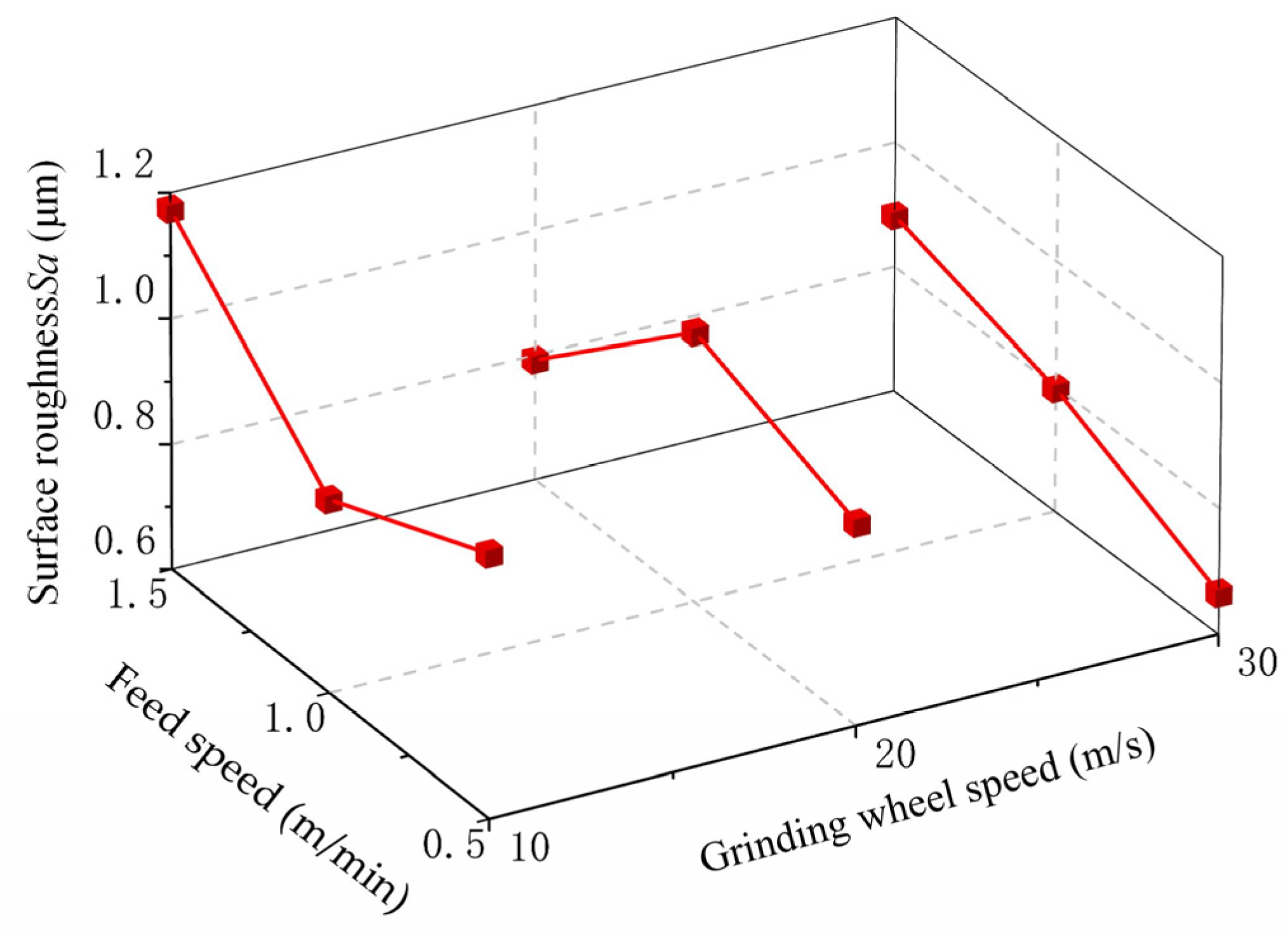
3.2. Optimization of Electroplastic-Assisted Grinding Process Parameters

Under the selected electrical parameters, nine groups of experiments were carried out according to an orthogonal table. The surface roughness of the grinding surface was quantitatively analyzed by a laser confocal microscope. Five positions were randomly selected for each group of samples to measure and take the average value. The experimental scheme and results are shown in Table 5.
The experimental signal-to-noise ratio (S/N) can be used to define the degree, and its value can be used to define the degree of deviation of the output result from the expected value. A higher (S/N) correlates with approaching optimal performance indices. As a measure of experimental robustness, S/N can be divided into three types of characteristic indicators: large, small, and eye-sighted. Considering that the experimental purpose is to optimize the electroplastic-assisted grinding performance of ductile iron, the surface roughness Sa is selected as the target response value, so it is suitable for the small characteristic S/N, which is calculated by the following formula:
η = 10   log 1 n i = 1 n y 2
In the formula, y is the experimental sample data; n is the number of output characteristics; η is the signal-to-noise ratio (S/N). The experimental data and signal-to-noise ratio results are shown in Table 6.
By comparing the experimental results, the optimal combination of grinding parameters under the electrical parameters of current 600 A, frequency 200 Hz, and duty cycle 50% is a grinding wheel speed of 30 m/s, a feed speed of 0.5 m/min, and a grinding depth of 10 μm. Five repeated experiments were carried out with this set of parameters. The measured surface roughness Sa was averaged, and the result was 0.208 ± 0.14 μm, which was significantly lower than the orthogonal experimental results. Figure 7 is the surface morphology of the workpiece processed by the optimal parameters of electroplastic-assisted grinding. Compared with conventional grinding, there is less surface plastic accumulation of electroplastic-assisted grinding under optimized parameters and the furrow is shallower. There are no defects such as pits and cracks, and the surface quality is improved, which proves the superiority of electroplastic-assisted grinding.
In order to research the influence of each variable on the surface roughness Sa, the range analysis of the orthogonal test data was carried out. The study determined the impact of grinding wheel speed, feed speed, and grinding depth on the surface quality of electroplastic-assisted grinding of ductile iron. The results of the range analysis are shown in Table 7. Kj represents the average value of surface roughness Sa for each respective factor at level j, where j = 1, 2, 3. R represents the range. The influence of surface roughness Sa of ductile iron electroplastic-assisted grinding from large to small is grinding wheel speed, grinding depth, and feed rate.

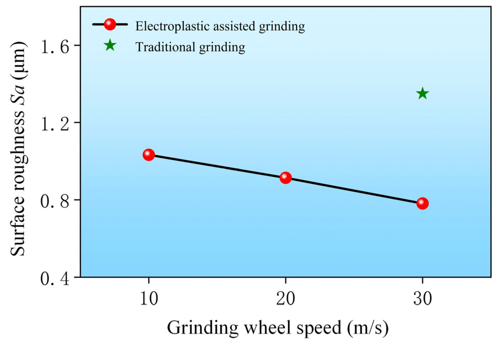
3.2.1. Influence of Grinding Wheel Speed

Figure 8 illustrates that an increased grinding wheel speed correlates with reduced workpiece surface roughness. At the same time, the difference between electroplastic-assisted grinding and conventional grinding can be seen. Grinding is a multi-cutting-edge collaborative processing process. With the increase in grinding wheel speed, the number of abrasive grains acting on the surface of the workpiece per unit of time increases. The plastic deformation speed of the workpiece surface under the grinding force is lower than the material removal speed, and the grinding process tends to be stable, thereby obtaining a smaller surface roughness value. At lower grinding wheel speeds, the plastic deformation of the workpiece surface leads to excessive material accumulation along the grinding direction, posing challenges for prompt removal and resulting in the formation of plastic build-up on the workpiece surface.
As shown in Figure 9, when the grinding wheel speed increases from 10 m/s to 30 m/s, the plastic accumulation phenomenon is significantly reduced and the surface quality is significantly improved. It is noteworthy that in electroplastic-assisted grinding, unlike conventional grinding, no discernible surface cracks were observed across varying grinding wheel speeds. Due to intense friction between abrasive particles and the workpiece surface during grinding, substantial heat is inevitably generated, and the combination of thermal stress and mechanical stress can readily induce surface crack defects. With the help of electroplasticity, the plasticity of the workpiece is improved, and the fluidity of the grinding deformation zone is enhanced. Affected by the thermal effect, the grinding surface has a thermal expansion, which effectively inhibits the initiation and propagation of surface cracks.
In fact, the pulse current acting on the metal workpiece can cause a crack arrest effect. The presence of cracks obstructs current conduction, leading to an increased local current density at the crack tip. Due to Joule heating, the temperature at the crack tip increases rapidly, thereby mitigating stress concentration and achieving crack arrest. In addition, the athermal effects also play a unique role in suppressing cracks. Residual stress is considered to be an important factor in crack formation [39]. Pulse current induces the electron wind effect, facilitating enhanced dislocation motion that contributes to the mitigation of residual stress on the ground surface.

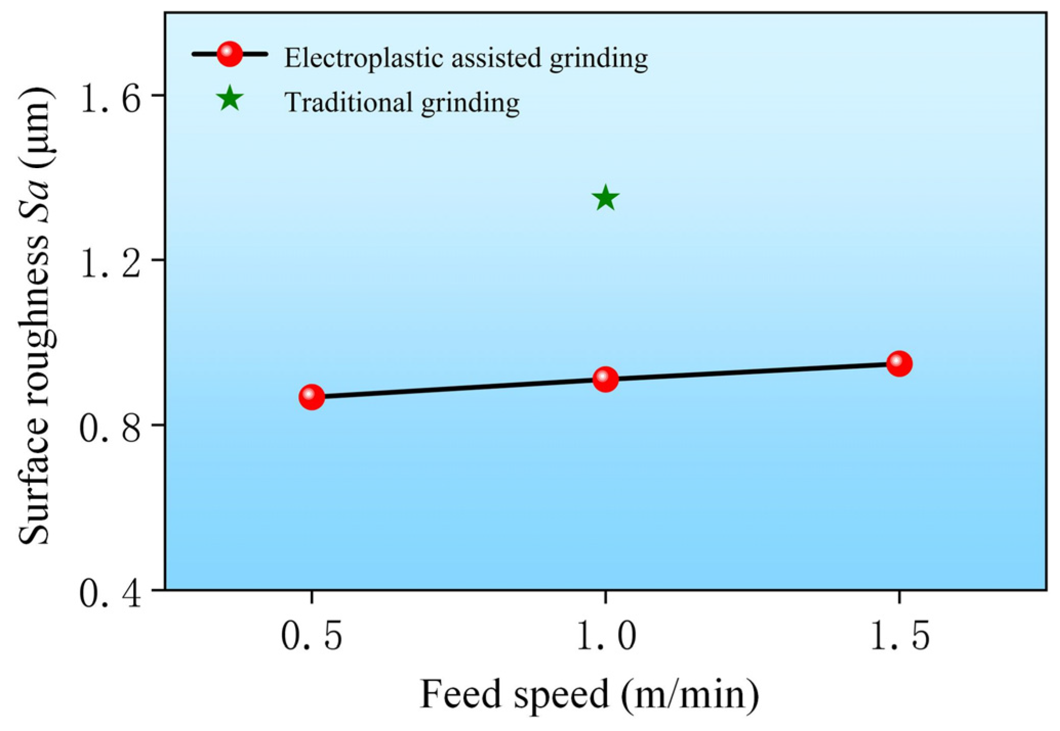
3.2.2. Influence of Feed Rate

Figure 10 illustrates a gradual increase in workpiece surface roughness with higher feed rates. The principal factor is attributed to the escalation in material removal per unit time of the grinding wheel with increasing feed speed, resulting in decreased grinding forces and heightened susceptibility of surface material removal through spalling, thereby diminishing grinding stability. In addition, greater friction between the grinding wheel and the workpiece increases the grinding zone temperature, resulting in thermal softening and higher chances of irregular grinding marks. The feed rate also affects the performance of the grinding wheel. Considering the combined effect of plastic strengthening and feed rate increase. Under the electroplastic-assisted process, the material removal efficiency surface is improved, and the output of wear debris per unit time is increased. The grinding process may lead to wheel surface adhesion due to challenges in chip evacuation, hindering the exposure of fresh, sharp abrasive grains and consequently diminishing the self-sharpening capability of the grinding wheel, thereby impacting grinding quality. Nevertheless, the surface roughness value under electroplastic-assisted grinding is still much smaller than that of conventional grinding.
As shown in Figure 11a,b, with the increase in feed rate, the probability of pits and plastic accumulation on the grinding surface increases, which has a non-negligible effect on the surface quality of the workpiece. As a common morphological defect in the grinding of ductile iron, surface pits are usually formed by brittle peeling of materials or exfoliation of spherical graphite. The analysis shows that the plasticity of the workpiece is improved under the action of electroplastic assistance, the brittle stripping of the material is difficult, and the shedding of spherical graphite becomes the main cause of the pit. As a heterogeneous metal material, ductile iron is affected by spherical graphite, and there are hardness differences and stress inhomogeneity in the workpiece. The high feed rate makes it difficult for the grinding force and grinding heat to act uniformly on the surface of the workpiece. The hardness of the graphite sphere is low, and it is easier to remove to form pits. On the other hand, the increase in feed rate reduces the unit grinding force, which in turn aggravates the plastic deformation at the local position and increases the degree of plastic accumulation on the surface of the workpiece.

3.2.3. Influence of Grinding Depth

It can be seen from Figure 12 that there is a significant difference between electroplastic-assisted grinding and conventional grinding. In electroplastic-assisted grinding, the higher the grinding depth, the greater the surface roughness of the workpiece. As the grinding depth increases, the abrasive grains exert a greater surface area interaction with the workpiece, thereby intensifying heat accumulation within the grinding zone. In the thermal effect, the workpiece surface is prone to overheating and burning, which causes the surface roughness value Sa to increase. In addition, excessive grinding depth may reduce the stability of the cutting process, resulting in an increase in the grinding resonance amplitude of the machined surface, and the irregular interaction between the abrasive particles and the workpiece surface, which may lead to a decrease in surface quality. Due to the existence of minimum chip thickness in grinding, maintaining the grinding depth within a reasonable range can effectively avoid the elastic and plastic deformation caused by the scratching and ploughing stages. This is conducive to the stable formation and discharge of wear debris, improving the material removal efficiency while achieving a higher surface quality. Figure 13a is the surface topography under the grinding depth of 10 μm. Due to the lack of grinding depth, the grinding process is greatly affected by the scratching and ploughing stages, resulting in a small amount of plastic accumulation on the surface of the workpiece. As shown in Figure 13b, as the grinding depth increases to 30 μm, a large number of adhesion points appear on the grinding surface. With the increase in the contact stress between the abrasive grain and the surface of the workpiece, it is difficult to discharge the wear debris. Moreover, significant thermal energy is produced during grinding at increased depths, causing the surface material of the workpiece to soften and promoting the formation of adhesive junctions. In addition, due to the untimely chip removal, it is also possible to accumulate debris on the surface of the grinding wheel and produce adhesion. As a result, the number of effective abrasive particles in the grinding wheel decreases, and the cutting force in the contact area is not uniform, making it easy to produce the rough furrow shown in Figure 13b.
In order to further analyze the coupling effect between grinding parameters assisted by electroplasticity, Figure 14 is constructed according to the experimental results to illustrate the relationship between surface roughness Sa and grinding parameters. Despite the findings from the orthogonal test indicating a propensity for surface quality degradation with higher feed speeds and grinding depths, the trend in surface roughness Sa at lower grinding wheel speeds deviates slightly from experimental expectations. As shown in Figure 14, the grinding wheel maintains a low speed of 10 m/s, and the surface roughness Sa decreases to a certain extent when the feed speed increases from 0.5 m/min to 1.0 m/min and the grinding depth increases from 10 μm to 20 μm. As mentioned above, the grinding wheel speed is directly related to the plastic deformation of the workpiece during grinding. With respect to enhancing workpiece plasticity, plastic deformation and grinding performance are notably responsive to variations in grinding wheel speed, with a pronounced propensity for plastic accumulation observed under conditions of lower speed. On this basis, it is difficult to generate sufficient cutting forces to remove material by choosing a lower feed rate and depth of cut.
The surface morphology under the corresponding working conditions is shown in Figure 15a, and there is noticeable plastic accumulation on the surface. As depicted in Figure 15b, with the escalation of feed rate and grinding depth, there is a progressive rise in grinding force, thereby diminishing the likelihood of plastic accumulation. Concurrently, due to the heightened grinding force, minor instances of adhesion points and pits emerge on the grinding surface, while the furrows exhibit a tendency towards increased roughness. In contrast, further increasing the grinding wheel speed makes the material removal speed of the workpiece surface faster than the plastic deformation. When maintaining the grinding wheel speed at 20 m/s, the surface roughness Sa escalates proportionally with increasing feed speed and grinding depth, aligning consistently with findings derived from the orthogonal test.

4. Conclusions

In the current study, the introduction of pulse current can significantly improve the grinding surface quality of ductile iron. Surface roughness Sa is primarily influenced by grinding wheel rotation speed, followed by feed speed, with grinding depth exerting comparatively lesser influence. According to the Taguchi method, optimal parameters include a grinding wheel linear speed of 30 m/s, a feed speed of 0.5 m/min, and a grinding depth of 10 μm, resulting in a surface roughness value of 0.208 μm.
(1) The grinding surface roughness of ductile iron decreases with the increase in grinding wheel speed. Compared with conventional grinding, there is no noticeable crack on the grinding surface under the action of pulse current. In contrast, the improvement of plasticity also has an adverse effect on surface quality, such as plastic accumulation. The issue is mitigated through the implementation of a higher grinding wheel speed (30 m/s), resulting in a 24.4% reduction in surface roughness Sa. At lower grinding wheel speeds (10 m/s), a strategic increase in feed rate and grinding depth can counterbalance the detrimental impacts of enhanced plasticity.
(2) As the feed rate in electroplastic grinding is raised from 0.5 m/min to 1.5 m/min, there is an observed 9.3% increase in surface roughness Sa. Augmentation of plasticity intensifies thermal softening within the grinding zone and enhances the production of wear debris As a result, the self-sharpness of the grinding wheel becomes worse, and the surface of the workpiece is prone to plastic accumulation and rough furrows.
(3) Upon increasing the grinding depth from 10 μm to 30 μm, there is a corresponding 10% rise in surface roughness Sa. Enhancement of plasticity reduces the difficulty in wear debris adhesion to machined surfaces. Therefore, it is necessary to reduce the grinding depth appropriately.

Author Contributions

Conceptualization, D.J. and T.G.; Methodology, D.J. and X.W.; Software, Y.Z., X.W. and R.X.; Validation, Y.Z.; Investigation, E.G.; Resources, E.G. and T.G.; Data curation, R.X. and H.Y.; Writing—original draft preparation, S.F.; Writing—review and editing, S.F.; Visualization, H.Y.; Project administration, X.L.; Funding acquisition, X.J. All authors have read and agreed to the published version of the manuscript.

Funding

This research was funded by China Postdoctoral Science Foundation Funded Project, grant number 2023M732826. Program for Young Talents of Science and Technology in Universities of Inner Mongolia Autonomous Region, grant number NJYT23022. National Natural Science Foundation of China, grant number 12272189. Liaoning Provincial Natural Science Foundation Project (Doctoral Research Start-up Project), grant number 2024-BS-239.

Data Availability Statement

The data presented in this study are available in this article.

Acknowledgments

The author acknowledges the preliminary contributions of Jiahao Liu and Dongzhou Jia.

Conflicts of Interest

Rui Xue was from Tianjin TANHAS Technol Co Ltd. Taiyan Gong and Haijun Yang were from The First Machinery Group, Inner Mongolia Ruite Precision Mould Co., Ltd. The remaining authors declare that the research was conducted in the absence of any commercial or financial relationships that could be construed as a potential conflict of interest.

References

  1. Yang, H.; Wang, X.; Liu, W.; Huang, W.; Wu, M.; Xue, M.; Li, L. Influence of distribution and size of graphite particle on the machinability of nodular cast iron. Eng. Fract. Mech. 2024, 297, 109882. [Google Scholar] [CrossRef]
  2. Fragassa, C. Investigating the material properties of nodular cast iron from a data mining perspective. Metals 2022, 12, 1493. [Google Scholar] [CrossRef]
  3. Torshizian, M.R.; Aliakbari, K.; Ghonchegi, M. Failure analysis of ductile iron differential housing spline in 4WD passenger car. Int. J. Met. 2021, 15, 587–601. [Google Scholar] [CrossRef]
  4. Colin, G.E.; Cruz, R.A.; Reyes, C.G.; Tellez, R.J.; Magana, H.A. Microstructural and mechanical assessment of camshafts produced by ductile cast iron low alloyed with vanadium. Metals 2021, 11, 146. [Google Scholar] [CrossRef]
  5. Hou, N.; Ding, N.; Qu, S. Failure modes, mechanisms and causes of shafts in mechanical equipment. Eng. Fail. Anal. 2022, 136, 106216. [Google Scholar] [CrossRef]
  6. Tkaya, M.B.; Mezlini, S.; El, M.M. On some tribological effects of graphite nodules in wear mechanism of SG cast iron: Finite element and experimental analysis. Wear 2009, 267, 535–539. [Google Scholar] [CrossRef]
  7. Benedetti, M.; Fontanari, V.; Lusuardi, D. Effect of graphite morphology on the fatigue and fracture resistance of ferritic ductile cast iron. Eng. Fract. Mech. 2019, 206, 427–441. [Google Scholar] [CrossRef]
  8. Yang, H.; Wang, Z. The different electroplastic effects of cutting directions during the turning process of Ti-6Al-4V titanium alloy. Int. J. Mater. Prod. Technol. 2023, 67, 155–165. [Google Scholar] [CrossRef]
  9. Zhao, L.; Chen, G.; Liu, J.; Wei, H.; Huang, J. Effect of pulse current parameters on electroplastically assisted dry cutting performance of W93NiFe alloy. Int. J. Adv. Manuf. Technol. 2023, 131, 2123–2131. [Google Scholar] [CrossRef]
  10. Ruszkiewicz, B.J.; Grimm, T.; Ragai, I.; Mears, L.; Roth, J.T. A review of electrically-assisted manufacturing with emphasis on modeling and understanding of the electroplastic effect. J. Manuf. Sci. Eng. 2017, 139, 110801. [Google Scholar] [CrossRef]
  11. Li, H.; Peng, L.F.; Meng, B.; Xu, Z.T.; Wang, L.L.; Ngaile, G.; Fu, M.W. Energy field assisted metal forming: Current status, challenges and prospects. Int. J. Mach. Tools Manuf. 2023, 192, 104075. [Google Scholar] [CrossRef]
  12. Peng, L.; Mai, J.; Jiang, T.; Lai, X.; Lin, Z. Experimental investigation of tensile properties of SS316L and fabrication of micro/mesochannel features by electrical-assisted embossing process. J. Micro Nano-Manuf. 2014, 2, 021002. [Google Scholar] [CrossRef]
  13. Dai, Z.; Jin, K.; Kou, Y. An electroplastic constitutive model of fcc metals and their alloys under high current density. Mech. Mater. 2024, 189, 104878. [Google Scholar] [CrossRef]
  14. Xu, Z.; Jiang, T.; Huang, J. Electroplasticity in electrically-assisted forming: Process phenomena, performances and modelling. Int. J. Mach. Tools Manuf. 2022, 175, 103871. [Google Scholar] [CrossRef]
  15. Wu, C.; Zhou, J.; Liu, B. Experimental and simulated investigation of the deformation behavior and microstructural evolution of Ti6554 titanium alloy during an electropulsing-assisted microtension process. Mater. Sci. Eng. A 2022, 838, 142745. [Google Scholar] [CrossRef]
  16. Liu, J.; Jia, D.; Fu, Y.; Kong, X.; Lv, Z.; Zeng, E.; Gao, Q. Electroplasticity effects: From mechanism to application. Int. J. Adv. Manuf. Technol. 2023, 131, 3267–3286. [Google Scholar] [CrossRef]
  17. Xiang, S.; Zhang, X. Dislocation structure evolution under electroplastic effect. Mater. Sci. Eng. A 2019, 761, 138026. [Google Scholar] [CrossRef]
  18. Fan, Y.; Fan, H.; Hao, Z. Effect of pulsed current on plastic deformation of Inconel 718 under high strain rate and high temperature conditions. J. Alloys Compd. 2023, 943, 169150. [Google Scholar] [CrossRef]
  19. Sprecher, A.F.; Mannan, S.L.; Conrad, H. Overview no. 49: On the mechanisms for the electroplastic effect in metals. Acta Metall. 1986, 34, 1145–1162. [Google Scholar] [CrossRef]
  20. Dimitrov, N.K.; Liu, Y.; Horstemeyer, M.F. Electroplasticity: A review of mechanisms in electro-mechanical coupling of ductile metals. Mech. Adv. Mater. Struct. 2022, 29, 705–716. [Google Scholar] [CrossRef]
  21. Egea, A.J.S.; Rojas, H.A.G.; Montaña, C.A.M.; Echeverri, V.K. Effect of electroplastic cutting on the manufacturing process and surface properties. J. Mater. Process. Technol. 2015, 222, 327–334. [Google Scholar] [CrossRef]
  22. Hameed, S.; Gonzalez Rojas, H.A.; Sánchez Egea, A.J.; Alberro, A.N. Electroplastic cutting influence on power consumption during drilling process. Int. J. Adv. Manuf. Technol. 2016, 87, 1835–1841. [Google Scholar] [CrossRef]
  23. Kinsey, B.; Cullen, G.; Jordan, A.; Mates, S. Investigation of electroplastic effect at high deformation rates for 304SS and Ti–6Al–4V. CIRP Ann. 2013, 62, 279–282. [Google Scholar] [CrossRef]
  24. Zhu, R.; Tang, G.; Shi, S.; Fu, M. Effect of electroplastic rolling on deformability and oxidation of NiTiNb shape memory alloy. J. Mater. Process. Technol. 2013, 213, 30–35. [Google Scholar] [CrossRef]
  25. Troitskiy, O.A.; Stashenko, V.I. Electroplastic wire drawing: A promising method of production of lightweight wire and cable. J. Mach. Manuf. Reliab. 2015, 44, 758–765. [Google Scholar] [CrossRef]
  26. Qian, L.; Zhan, L.; Zhou, B.; Zhang, X.; Liu, S.; Lv, Z. Effects of electroplastic rolling on mechanical properties and microstructure of low-carbon martensitic steel. Mater. Sci. Eng. A 2021, 812, 141144. [Google Scholar] [CrossRef]
  27. Wang, H.; Chen, L.; Liu, D.; Song, G.; Tang, G. Study on electropulsing assisted turning process for AISI 304 stainless steel. Mater. Sci. Technol. 2015, 31, 1564–1571. [Google Scholar] [CrossRef]
  28. Yuan, M.; Wang, J.; Wang, M.; Huang, K.; Wang, L.; Tian, Y. Enhanced carbide tool life by the electromagnetic coupling field for sustainable manufacturing. Int. J. Adv. Manuf. Technol. 2020, 108, 3905–3914. [Google Scholar] [CrossRef]
  29. Zhao, G.; Zhao, B.; Ding, W.; Xin, L.; Nian, Z.; Peng, J.; Xu, J. Nonconventional energy-assisted mechanical machining of difficult-to-cut materials and components in aerospace community: A comparative analysis. Int. J. Extrem. Manuf. 2024, 6, 022007. [Google Scholar] [CrossRef]
  30. Shao, Z.; Li, G.; Liu, W.; Wu, X.; Ma, G.; Wang, F. Advance in the research of electric pulse-assisted cutting. Int. J. Adv. Manuf. Technol. 2023, 127, 2107–2123. [Google Scholar] [CrossRef]
  31. Da Silva, R.B.; Lima, M.L.S.; Pereira, M.F.; Abrão, B.S.; Da Silva, L.R.R.; Bianchi, E.C.; Machado, A.R. A surface and sub-surface quality evaluation of three cast iron grades after grinding under various cutting conditions. Int. J. Adv. Manuf. Technol. 2018, 99, 1839–1852. [Google Scholar] [CrossRef]
  32. Furno, M.E.; Sosa, A.D. Surface integrity analysis of grinding on ductile iron. Int. J. Adv. Manuf. Technol. 2020, 110, 2067–2078. [Google Scholar] [CrossRef]
  33. Liu, J.H. Experimental Study on Electroplastic-Assisted Grinding of Ductile Iron; Liaoning University of Technology: Jinzhou, China, 2024. [Google Scholar]
  34. Rosentritt, M.; Schneider-Feyrer, S.; Kurzendorfer, L. Comparison of surface roughness parameters Ra/Sa and Rz/Sz with different measuring devices. J. Mech. Behav. Biomed. Mater. 2024, 150, 106349. [Google Scholar] [CrossRef]
  35. Nwaogu, U.C.; Tiedje, N.S.; Hansen, H.N. A non-contact 3D method to characterize the surface roughness of castings. J. Mater. Process. Technol. 2013, 213, 59–68. [Google Scholar] [CrossRef]
  36. Li, Q.; Li, R.; Chang, G.; Zhai, Q. Research of microstructure of spherical graphite iron by electropulsing annealing. J. Mater. Process. Technol. 2009, 209, 2015–2020. [Google Scholar] [CrossRef]
  37. Sheng, Y.; Hua, Y.; Wang, X.; Zhao, X.; Chen, L.; Zhou, H.; Li, W. Application of high-density electropulsing to improve the performance of metallic materials: Mechanisms, microstructure and properties. Materials 2018, 11, 185. [Google Scholar] [CrossRef]
  38. Yang, M.; Kong, M.; Li, C.; Long, Y.; Zhang, Y.; Sharma, S.; Yang, Y. Temperature field model in surface grinding: A comparative assessment. Int. J. Extrem. Manuf. 2023, 5, 042011. [Google Scholar] [CrossRef]
  39. Li, Y.; Chen, J.; Wang, J.; Shi, X.; Chen, L. Study on the effect of residual stresses on fatigue crack initiation in rails. Int. J. Fatigue 2020, 139, 105750. [Google Scholar] [CrossRef]
Figure 1. Microstructure of QT500-7 ductile iron sample by SEM: (a) morphology and distribution of graphite in the sample; (b) matrix microstructure in the sample.
Lubricants 12 00266 g001
Figure 2. Electroplastic-assisted grinding system for ductile iron.
Lubricants 12 00266 g002
Figure 3. Under the condition of grinding wheel speed of 30 m/s, feed speed of 1 m/min and grinding depth of 20 μm. Grinding surface roughness value (a) surface roughness value distribution of conventional grinding workpiece and (b) surface roughness value distribution of grinding workpiece under selected electrical parameters.
Lubricants 12 00266 g003
Figure 4. Surface morphology of conventional grinding (a) and electroplastic-assisted grinding (b) under laser confocal microscope. Surface morphology of conventional grinding (c) and electroplastic-assisted grinding (d) under scanning electron microscope.
Lubricants 12 00266 g004
Figure 5. Electroplastic-assisted grinding mechanism.
Lubricants 12 00266 g005
Figure 6. The cross-section current distribution of the starting point (2.73 s) and the ending point (4.77 s) under the selected electrical parameters.
Lubricants 12 00266 g006
Figure 7. (a) The SEM morphology of the grinding surface obtained by using the optimized parameters (b) measured surface roughness values obtained using a laser confocal microscope.
Lubricants 12 00266 g007
Figure 8. Effect of grinding wheel speed on surface roughness Sa.
Lubricants 12 00266 g008
Figure 9. Effect of different grinding wheel speed surface topography assisted by electroplasticity: (a) the SEM image of the grinding wheel when the rotation speed is 10 m/s; (b) the SEM image of the grinding wheel when the rotation speed is 30 m/s.
Lubricants 12 00266 g009
Figure 10. Effect of feed rate on surface roughness Sa.
Lubricants 12 00266 g010
Figure 11. Effect of different feed rates on grinding surface morphology with electroplastic assistance: (a) laser confocal microscope images at a feed rate of 0.5 m/min; (b) laser confocal microscope images at a feed rate of 1.5 m/min.
Lubricants 12 00266 g011
Figure 12. Effect of grinding depth on surface roughness Sa.
Lubricants 12 00266 g012
Figure 13. Effect of different feed speeds on grinding surface topography assisted by electroplasticity: (a) SEM images at 10 μm grinding depth; (b) SEM images at 30 μm grinding depth.
Lubricants 12 00266 g013
Figure 14. Effect of grinding parameters coupling on surface roughness Sa.
Lubricants 12 00266 g014
Figure 15. Effect of grinding parameters on surface topography: (a) the SEM image (above) and the laser confocal microscope image (below) of the grinding wheel speed of 10 m/s, the feed speed of 0.5 m/min, and the grinding depth of 10 μm were obtained; (b) the SEM image (above) and the laser confocal microscope image (below) of the grinding wheel speed of 10 m/s, the feed speed of 1.0 m/min, and the grinding depth of 20 μm were obtained.
Lubricants 12 00266 g015
Table 1. Standard chemical composition of QT500-7 ductile iron (wt%).
ElementCSiMnSMgRe
Content3.55–3.852.34–2.86≤0.6≤0.0250.02–0.040.03–0.05
Table 2. Standard mechanical properties of QT500-7 ductile iron.
MaterialTensile Strength
(MPa)
Yield Strength
(MPa)
Elongation
(%)
Hardness
(HB)
QT500-7≥500≥320≥7170–230
Table 3. Electroplastic-assisted grinding factor level table.
FactorSymbolLevel
123
Grinding wheel tangential speed (m/s)A102030
Feed speed (m/min)B0.51.01.5
Grinding depth (μm)C102030
Table 4. The range of experimental process parameters.
Process ParametersValue Ranges
Impulse current (A)600
Pulse frequency (Hz)200
Duty ratio (%)50
Grinding wheel speed (m/s)10–30
Feed speed (m/min)0.5–1.5
Grinding depth (μm)10–30
Table 5. Orthogonal test scheme and results.
Experiment
No.
Grinding Wheel Speed (m/s)Feed Speed (m/min)Grinding Depth (μm)Surface Roughness Sa
(μm)
1100.5101.017 ± 0.27
2101.0200.907 ± 0.26
3101.5301.174 ± 0.12
4200.5200.921 ± 0.16
5201.0301.029 ± 0.28
6201.5100.792 ± 0.23
7300.5300.665 ± 0.31
8301.0100.797 ± 0.32
9301.5200.882 ± 0.24
Table 6. Surface roughness N/S response table.
LevelGrinding Wheel Speed (m/s)Feed Speed
(m/min)
Grinding Depth
(μm)
1−0.23061.37071.2833
20.83070.85680.8844
32.20170.57430.6340
Table 7. Range analysis results.
ProjectResultGrinding Wheel Speed
(m/s)
Feed Speed
(m/min)
Grinding Depth
(μm)
Surface roughness
Sa (μm)
K11.0330.8680.869
K20.9140.9110.903
K30.7810.9490.956
R0.2520.0810.087
Order132
Disclaimer/Publisher’s Note: The statements, opinions and data contained in all publications are solely those of the individual author(s) and contributor(s) and not of MDPI and/or the editor(s). MDPI and/or the editor(s) disclaim responsibility for any injury to people or property resulting from any ideas, methods, instructions or products referred to in the content.

