Article

Exploring the Boundaries of Electrically Induced Bearing Damage in Grease-Lubricated Rolling Contacts

1
Department of Mechanical Engineering, Auburn University, Auburn, AL 36849, USA
2
Department of Chemistry and Biochemistry, Auburn University, Auburn, AL 36849, USA
*
Author to whom correspondence should be addressed.
Lubricants 2024, 12(8), 268; https://doi.org/10.3390/lubricants12080268
Submission received: 13 June 2024 / Revised: 16 July 2024 / Accepted: 25 July 2024 / Published: 28 July 2024
(This article belongs to the Special Issue Tribology of Electric Vehicles)

Abstract

:
As public attention is increasingly drawn toward more sustainable transportation methods, the popularity of electric vehicles (EVs) as part of the solution is rapidly expanding. Operating conditions within EVs can be severe compared to standard combustion powertrains, and the risk of electrical arcing across mechanical surfaces from electric leakage currents incites additional concern. This study employed a series of electro-tribological tests utilizing various moving patterns to improve understanding of the driving conditions for electrically induced bearing damage (EIBD). Rolling ball-on-disk tests were performed with different polyurea-thickened greases. Rotational tests were initially run at various speeds and test durations, but electrical damage was limited. However, electrical damage was unmistakable when a reciprocating motion was used at different track lengths and speeds. These results suggest that the conditions associated with the track length, such as the number of directional changes and speed-dependent film thickness, play a considerable role in forming electrical damage. This work provides critical insights into the mechanisms of EIBD in EVs and other electrical systems. It highlights the importance of understanding the operational conditions that contribute to EIBD, which can lead to improved designs and maintenance practices, ultimately enhancing the efficiency and lifespan of these systems.

Graphical Abstract

1. Introduction

1.1. Electrification of the Transportation Industry

Modern EVs come in various forms, from battery EVs to those powered by a continuous electrical supply like metropolitan trolleys and electrified rail lines. Influenced by cultural and political factors, EVs on roads increased five-fold from 2018 to 2022 [1]. This surge in demand led the automotive industry to invest billions in enhancing domestic electromobility manufacturing [2]. These investments also fueled research into complex drivetrain architectures and control systems to balance performance and efficiency. While proprietary materials and redesigned motor configurations enable competitive performance, they also bring unique tribological challenges and opportunities.

1.2. Greases in Elastohydrodynamic Lubrication (EHL)

Machine components or elements in EVs face harsher conditions, often with temperatures surpassing 150   and increased shear rates due to enhanced acceleration capabilities [3,4,5,6]. About 80–90% of machine elements, like gears and rolling element bearings, rely on grease lubrication [7]. Greases provide robust load support and prevent lubricant leakage, extending sealed-life-bearing longevity [8]. Greases comprise a mineral- or synthetic-based oil with an added thickening component, called a thickener, which accounts for between 2% and 30% of the grease. Thickeners are aggregated, fibrous structures of intertwined molecules, polymers, or particles [9]. Adding the thickener gives greases a semi-solid consistency, allowing the grease to remain in place and form different lubricant channels depending on how the grease is loaded [10,11]. Many thickener options, such as metallic soap, polyurea, polymer, clay, and silica-based thickeners, offer a wide range of capabilities, depending on the application [7]. This work employs polyurea as the thickener, which is commonly used for electric motors and vehicles and is often considered the best option. Additive packages refine the grease’s performance after combining the thickener matrix and liquid base oil.
In electrified applications like EVs, lubricant additive packages require special attention. Additives such as extreme pressure (EP) or viscosity modifiers (VM) interact differently with the lubricated surface. Physisorption additives weakly bond to surfaces via van der Waals bonds, as is common for fatty acid friction modifiers [12]. Chemisorption additives promote a chemically-bonded film deposition of sacrificial material across the contact area [13,14]. While these tribo-films can protect surfaces in EP applications or from degradation reactions, they may affect the material’s conductivity [14,15,16]. EV mechanical components are prone to morphological damage from electric currents and stray voltages bridging lubricated contacts. Adjusting additive packages can mitigate electrical-related damage, presenting an additional approach to damage prevention [14,15,16].
When modeling EHL film thickness in contacts, traditional approaches rely on base oil properties, mainly viscosity, as it constitutes the largest volumetric portion of the grease. This method assumes that the grease thickener behaves like a sponge, absorbing and releasing base oil based on the mechanical conditions and lubrication needs of the contact [17]. While effective for oil-lubricated contacts, it overlooks the intricate rheological nature of grease. Some studies suggest that the thickener significantly affects the film’s thickness more than previously believed. Scarlett et al. found that bearings’ film formation was not reliant on oil bleed but rather on a layer of decomposed thickener forming a highly viscous, oily material [18]. Others propose that shearing conditions within the grease degrade the thickener, leading to thickener particles entering the contact and contributing to film formation [19,20,21,22]. Initially, films were thicker than predicted using base oil viscosity for fully flooded conditions but decreased to a steady-state value below this prediction during severe conditions [20,23,24]. Film thickness losses may result from starvation at the contact inlet due to an inadequate lubricant flow with grease and a lack of a continuous grease supply [23]. Ultimately, a combination of this layer and some replenishment could sustain a steady-state film that is smaller than expected for fully flooded conditions [25].
Furthermore, in grease EHL lubrication, striated cavitation patterns intersecting the running track at approximately 45 degrees indicate the lack of lubricant flow once expelled from the contact region [25]. These branches increase in size with distance from the track and remain unchanged even days after tests. Zhang et al. also modeled this approach, investigating if a thickener layer contributes to film thickness. Their model suggests that different thickener concentrations and structures influence the rate of thickener deposition and base oil bleed [26]. This work underscores the theory that additional mechanisms beyond simple EHL film generation may be at play.

1.3. Causes of Electrical Damage in Electric Motors

The complex electrical environment in motors can lead to stray charges arcing across lubricated contacts. Common EVs store a charge in a DC battery, typically operating between 300 V to 800 V [27,28]. A DC/DC converter reduces this voltage to a more manageable level for other components. Then, an inverter, often a Pulse Width Modulation (PWM) Inverter, converts the DC supply to a variable-output AC supply [29]. The AC supply powers a three-phase AC motor, usually controlled by a variable frequency drive (VFD).
PWM inverters, essential for variable-speed applications, generate shaft voltages due to rapid pole-switching [30]. They mimic sinusoidal AC waves through stepped pulses to ensure the efficiency and dynamic performance of three-phase motors [31,32]. However, the unbalanced voltage can induce a high-frequency common mode voltage (CMV) [33]. Additional voltages arise from magnetic flux asymmetry linked to shaft speed. Factors like uneven stator windings, manufacturing tolerances, or rotor eccentricities cause asymmetries [34,35,36,37,38,39]. The Triboelectrification Effect, where relative motion generates a static charge, can occur, potentially discharging across bearing surfaces [29,30]. These generated voltages tend to discharge across lubricated contacts, especially in systems with high-resistivity lubricants, increasing the risk of damaging discharges.
Capacitance charge accumulates when a dielectric lubricant separates conductive materials in bearings. Despite hydrocarbon lubricants being insulators, bearing voltages, particularly CMV, can trigger an unexpected current flow [40]. Currents often take the path of least resistance, flowing through shaft bearings or lubricated contacts before returning through the ground. When a CMV charges the contact beyond the lubricant’s insulating threshold, it leads to destructive EDM current pulses [30,41,42]. For a 1.5 kW induction motor, EDM currents range from 0.2 A to 1.4 A [43].

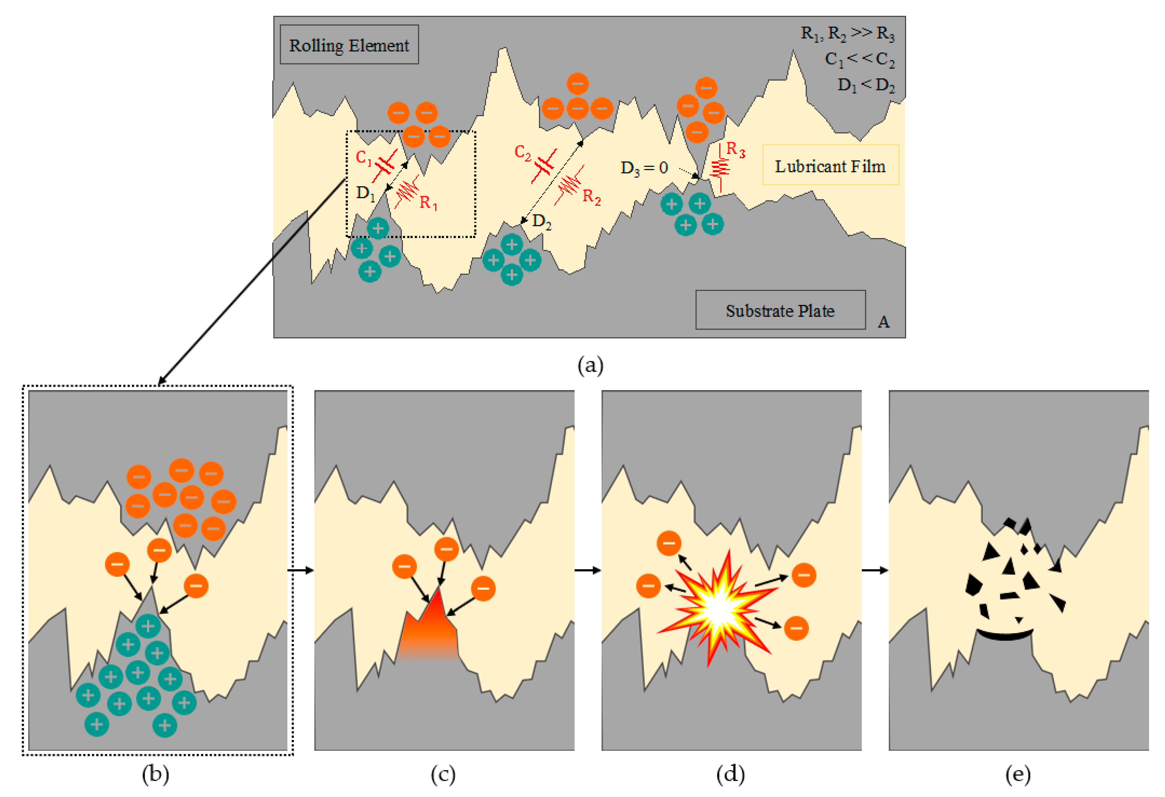
1.4. Arc Formation and Propogation

Mechanisms are well established in the field of electrical contacts to explain arc propagation across contacts. However, most were not directly studied for grease lubrication. Based on these mechanisms, a simplified model is proposed. This model, illustrated in Figure 1, presents three different film thickness conditions. At D3, the asperities are in contact, facilitating the ohmic conduction of electricity. These contacting asperities represent boundary lubrication, where an insignificant lubricant film is present in the contact. This condition is expected for low-speed applications or under start/stop conditions. The little lubricant in the contact and the contact resistance between the asperities would provide a slight resistance, R3. D1 and D2, however, represent a generated film thickness. D2 is significantly larger than D1, and the fluid film is insulative against discharging. D1 represents the optimal film thickness for electrical discharge and damage. At this distance, asperities on the surface create an enhanced electric field from geometric and field enhancement factors [44]. This electric field generates electrons that are emitted towards the substrate plate. As the electric field intensifies, the asperity temperature rises exponentially, causing them to explode into a dense cloud of metal vapor plasma. This ablation is assumed to be the origin of pit formation. A resistance value is also expected for D1 and D2, as current will not flow unrestricted upon capacitive discharge.
Many factors affect the location and severity of electrical damage. These factors include surface materials, roughness, geometric irregularities, lubricant chemistry, loading conditions, ambient conditions, and electrical circuit variations [30,45,46]. Additionally, lubricants require thermal and electrical durability to combat the negative consequences of the introduced mechanism. Lubricants must also remain non-corrosive and chemically compatible with the advanced polymers, plastics, and conductive elements that are common to EV/HEV systems [47].

1.5. Electrical Damage to Mechanical Systems

In addition to traditional bearing damage, such as fatigue fractures (spalling), thermal cracking, smearing, skidding, and abrasive wear, bearing currents compound morphological failures [30,48]. Elevated surface damage from high interface power and low melting point materials can lead to premature bearing failure or retirement due to instability, vibration, noise, or more severe mechanical issues [17,49,50]. At the microscopic level, pitting occurs as a deep, melted crater, often accompanied by a concentrated presence of carbon and oxygen, indicating that lubricant degradation and surface damage co-occur [42,51]. Figure 2a shows an untested portion of the sample surface. Figure 2b depicts a representative SEM image of the electrical pitting from the current work: running 2 cm reciprocating tracks with a mineral-based grease for 5400 s. Wang et al. observed a direct relationship between the volume of electrical pitting and the material’s melting temperature, with higher amounts of pitting occurring with an increased supply current [52].
With prolonged electrical exposure, the number and density of pits increase, eventually leading to a satin-like surface finish [53]. This change in surface finish is referred to as frosting and is visible under low magnification, as seen in Figure 3. These figures are also from the current work: running 2 cm reciprocating tracks with a mineral-based grease for 5400 s. Physical characteristics, like surface roughness, are anticipated to change alongside surface finish alterations. Graf et al. observed that machining grooves and run-in damage became indiscernible under an increasing electrical load, as seen through a lighted microscope [54]. The electrical load can increase wear in sliding contacts, but the pitting and frosting may be worn away before it can be observed [55].
While pitting and frosting can be seen in rolling ball-on-disk tests, fluting is considered the most common form of electrical damage in complete bearings [30]. Fluting arises from rotating bearing elements exerting high pressures in regions of maximum radial force and minimal film thickness. These high-stress concentrations induce corrugations with each revolution, which are accentuated by mechanical vibrations and vibrations from the applied electric current [56]. While film thickness and loading parameters have some influence on groove formation, increasing current and exposure duration have the most significant impact on corrugation geometry and bearing temperature [39,57]. Lubricant decomposition, leading to oxidation and corrosion within bearings, also plays a substantial role in corrugation formation [39]. Electrically induced bearing failures are frequently observed in wind turbine bearings as well [48].
Solutions, such as grounding brushes/rings/straps, CMV signal filtering, ceramic or composite materials, and high-frequency grounding cables, have been implemented to mitigate issues in electrified machinery [29,30,49,58,59,60]. However, each solution has drawbacks; grounding brushes suffer from abrasive wear, composite/ceramic bearings are costlier and raise manufacturing concerns, and additional components may only be viable for some applications [49]. Instead of rerouting or insulating the bearing surfaces, altering the lubricant’s conductivity can extend a bearing’s life by reducing the electrical damage resulting from charging and discharging behavior [5,11,14,17,30,59,61,62,63,64].

2. Materials and Methods

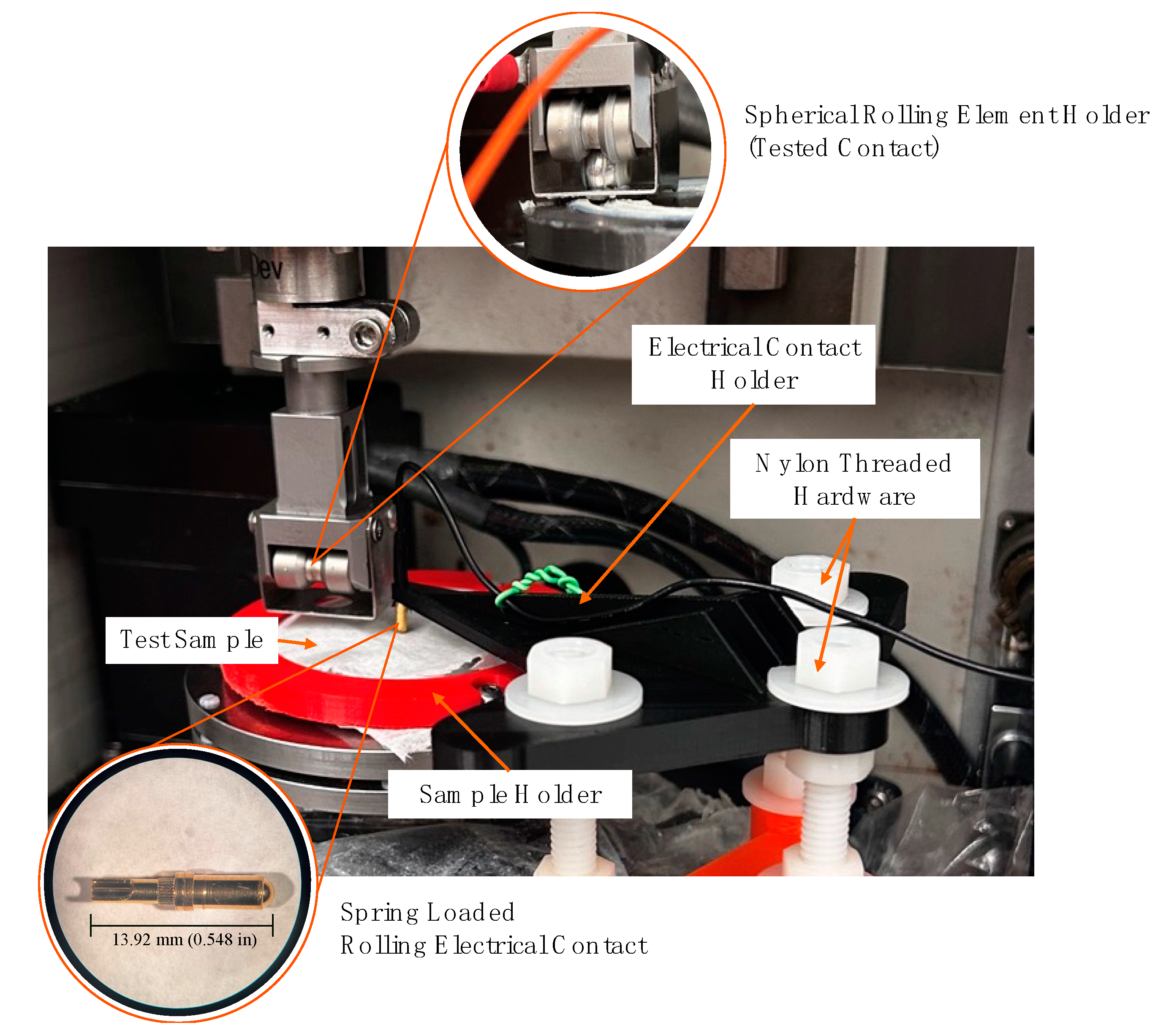
2.1. General Test Apparatus Overview

In our previous work, Bond et al. utilized bolted contacts to electrify a standard rolling spherical ball-on-disk test [51]. These reciprocating tests were conducted using a Bruker UMT3 tribometer (Bruker Corporation, Billerica, MA, USA) across a 1 cm track for 5400 s. Although pitting developed during these tests, the trials were limited to a short, constant track length. The test rig was modified to accommodate longer track lengths and rotational tests in the current work, better mimicking real-world bearing operating conditions. A rolling spring-loaded electrical contact was introduced to avoid tangled electrical leads during large angular displacements. This contact features a gold-plated brass alloy spherical rolling contact with a diameter of 2.31 mm. With 360 degrees of rotation for the contact tip, it provides a rolling connection rather than sliding. A 3D-printed PLA holder is attached to the Bruker UMT-3 base, securing the electrical contact on the test piece’s top surface. Nylon-threaded hardware (1/4”—20) provides vertical adjustability and isolates the electrical circuit from tribometer components. The threaded hardware screws are fastened to the base plate and the electrical contact holder with two nylon hex nuts and washers, as shown in Figure 4. Compared to intact bearing tests, single-element testing on a flat surface is more sensitive for detecting early-stage damage in less time. With fewer rolling elements, the contact geometries are simplified. Likewise, test time is reduced. The flat test disks simplify the SEM image capture and ensure repeatable results by minimizing vibrations and transient noise.

2.2. Electrical Circuit, Test Samples, & Mechanical Loading

The positive lead of a DC power supply is soldered to the spring-loaded electrical contact, while the negative lead is connected to a rolling fixture cradling a 9.525 mm (3/8 in) diameter spherical rolling element. A digital multimeter is connected in parallel to the electrical circuit to measure the voltage drop across the lubricating film. The applied voltage is held at 31 VDC throughout the circuit, and a 275 W (62 Ω) heating element is placed in series with the positive lead to add an electrical load. The circuit achieves a current of approximately 0.5 ADC. For this work, only DC currents were analyzed. AC currents apply cyclic stresses to the sample, which may be more applicable to specific EV applications. However, DC currents are proven to cause pitting damage without increasing the power supply or measurement complexity [65]. Furthermore, DC currents impart a steady-state electrical load on the sample. This loading is a critical driver in space charge accumulation, the fundamental theory of electrical contacts that was used as the foundation for Figure 1.
As previously mentioned, the dielectric strength of the grease generates a capacitive charge when exposed to the applied electrical load. This capacitive effect is illustrated in the idealized electrical circuit in Figure 5. For all tests, a constant normal force of 50 N is applied, resulting in a Hertz contact area of approximately 4.25 × 10⁻⁸ m2 and a Hertz contact pressure of 1.72 GPa. Combined, these two values result in a current flux of 11.1–13.3 MAmp/m2. The rolling element and rotating sample are composed of SAE 52,100 alloy steel for all testing. The rotating samples were 63.5 mm (2.5 in) in diameter, 6.35 mm (0.25 in) thick, and heat-treated to a hardness between 60 and 62 HRC. Surface profiles of three separate samples were measured using a stylus profilometer over 1 cm. Based on the average measurements for the three line scans, the average roughness is 1.284 µm, and the RMS roughness is 1.498 µm.

2.3. Grease Selection

Polyurea-thickened greases were chosen for this study due to their favorable properties. While lithium-based greases are commonly used, the rising cost of lithium batteries and concerns about reproductive toxicity have led to the popularity of alternative thickeners like polyurea. Polyurea offers improved oxidation and thermal resistance without the environmental or health concerns [21]. Mineral-based grease was used for all tests. This grease consisted of a mineral-based oil and polyurea thickener without additional additives. This study excluded additives to ensure that the pitting results were not influenced by the additive package’s chemistry. The grease was initially NLGI Grade 2, and the mineral-based oil was within the ISO 100 specification. A thin layer (~1.5 mm thick) of grease was applied to the intended contact path for all tests. Once the tests were completed, the surfaces were cleaned, and tests were run in different positions on the surface of the samples.

3. Results

3.1. Full Rotational Testing

The first tests employed continuous rotation at defined linear speeds of 0.01 m/s, 0.1 m/s, and 1.0 m/s. The tests were conducted for 5400 s. Figure 6 displays SEM images of the wear track on the flat sample after testing at all three speeds. The rotational tests failed to produce the expected pitting damage. This result was unexpected, but it may have been due to the development of a thicker film that reduced the arcing. Another possibility may be that the continuous motion did not allow an electrical charge to build at a single location along the track. Following Bond et al.’s findings [51], which showed increased electrical pitting at the ends of 1 cm tracks with the same mineral-based grease, the test methodology was adjusted to attempt to induce damage by augmenting the number of directional changes.

3.2. Complete Revolutions/Cycle Testing

Instead of continuous rotation, the subsequent testing phase involved additional stopping and directional changes. Two test cycles were implemented: one completing ten full revolutions before changing directions (10 rev./cycle), and another completing only one revolution before changing directions (1 rev./cycle). In the first condition (10 rev./cycle), the direction changed 43 times within 2 h. As shown in Figure 7a, no discernible electrical pitting damage was observed. The test duration was doubled, and the number of directional changes was increased by limiting complete rotations to 1 rev./cycle. Despite 940 directional changes over four hours, electrical pitting remained absent when examining the samples under SEM (Figure 7b).

3.3. Extended Track Reciprocating Testing

The lack of damage identified in Section 3.1 and Section 3.2 was unexpected. Given the damage created by Bond et al. with comparable electrical and mechanical loading on 1 cm tracks, the short reciprocating tests were revisited [57]. To verify that the lack of damage was not from the revised electrical circuit, multiple tests were conducted following the methodology of Bond et al. with a 1 cm track length [57]. After comparing the resulting electrical damage, it was confirmed that the lack of observed damage from rotational tests was not due to the switch from bolted to rolling connections. Likewise, the test methodology was expanded to increase the reciprocating track lengths to 2, 3, and 4 cm to determine the driving factors for inducting electrical damage. Unlike previous test setups, electrical damage was noticeable for the reciprocating tests at longer track lengths with mineral-based grease. Subsequently, triplicate tests were conducted for each of the three track lengths.
After each test, samples were examined under SEM, and the damage was quantified using MATLAB (Version R2023b). A custom script converted the SEM images to a binary format and removed other surface features, such as machining grooves. This process enabled the comparison of pit areas to undamaged regions. Percent damage was correlated with test parameters such as voltage measured across the contact, directional changes, rotational speed, and track length, as depicted in Figure 8. Given the UMT-3 data, a MATLAB script extracts the number of directional changes based on the angular velocity of the lower drive. The script also highlights the highest linear speed achieved during the test.
Based on the results shown in Figure 8a–c, the 2 cm tracks exhibited the highest level of damage compared to the other track lengths. The damage was compared to the test parameters, where surprising conclusions were drawn. First, the observed voltage across the contact varied between 0.5 to 1.5 V, yet no direct correlation was observed between the measured voltage and damage. The average voltage readings for each test are illustrated in Figure 8a. Second, it was anticipated that the number of directional changes would decrease with longer track lengths, as all tests were run for 5400 s. In addition, it was theorized that the damage would be proportional to the number of directional changes. Surprisingly, the relationship between the directional changes and damage was not proportionate, as illustrated in Figure 8b. Lastly, the maximum speed differences were ultimately track-length-dependent. The relationship between speed and damage is shown in Figure 8c. In all three graphs illustrated in Figure 8, the plot marker denotes the average between triplicate tests, and the standard deviation is represented with an error bar. Table 1 organizes the graphically illustrated data from Figure 8 by track length.

4. Discussion

Given the results identified in Section 3, different patterns were deduced. First and foremost, tests incorporating fully rotational or complete revolution/cycle were ineffective in recreating the electrical damage during the test duration. The authors attribute this lack of damage to two main factors: film thickness and charge dissipation. Regarding film thickness, the sustained motion from the first two test methodologies had ample time to reach the desired user-defined input speed. Likewise, higher speeds are expected to generate a more substantial lubricant film than the reciprocating alternatives. Due to limitations on the UMT3′s acceleration and deceleration capabilities during reciprocating tests, the short track length affects the maximum achievable speed. The fact that shorter reciprocating tests had a lower maximum speed may have resulted in thinner film thicknesses. Thicker films are expected to act as a more robust dielectric, resulting in more resistance against charge dissipation and electrical damage. However, thin films can allow conductive pathways, thereby mitigating damage.
Additionally, variations in the test methodologies could result in different charge dissipation patterns. The reciprocating tests had a much smaller radial displacement than the fully rotational or full revolution/cycle tests. As the ball rotates along the flat plate under continuous motion, the perpetual motion may not allow enough time for the charge to dissipate across the lubricated contact in a targeted burst. For the reciprocating tests, the start/start motion near the track ends may provide enough time for the accumulated charge to discharge in a concentrated burst. This theory would explain why the most severe pitting damage is prevalent where the track ends. Ultimately, the track length or maximum speed is presumed to influence the extent of the electrical damage due to the generated film or opportunities for charge dissipation.
During the image analysis of each SEM scan, several trends emerged. Firstly, most of the pitting was concentrated on the ridges of the machining grooves, with minimal pitting visible in the valleys, supporting the theory that visible electrical pitting results from exploded asperity peaks [44,66,67,68]. Figure 9 illustrates this, displaying electrical pitting solely along the most prominent asperity ridges. This pattern supports our proposed mechanism (Figure 1), reiterating that pits are the remnants of exploded or thermally deformed asperity peaks. Additionally, pits often appeared as melted, irregular shapes, frequently containing multiple layers of pitting within, as depicted in Figure 10. This increased surface area within each pit heightens the risk of corrosion and raises mechanical stresses, potentially causing surface fatigue to the bearing surfaces due to suboptimal surface characteristics. Lastly, under high SEM magnification, cracks radiated outward from the center of some pits, suggesting a high energy release during the pit formation process. While uncommon, these cracks, likely caused by the thermal expansion and residual stress that are associated with extreme arcing temperatures, can further contribute to surface fatigue or mechanical deformation. An example of crack propagation is shown in Figure 11. It is worth noting that pitting or crack formation was not present without applying an electrical potential. The formation of these cracks may be caused by the intense thermal effects of melting during the arcing or phase change event. While these cracks are not likely caused by surface fatigue, they may be evidence of changes in surface characteristics. These changes, such as hardening or quenching, could contribute to surface fatigue throughout the component’s lifetime.

5. Conclusions

This study investigated rolling bearing and ball-on-disk operating conditions that increase the susceptibility of electrically induced bearing damage, specifically pitting. A current was passed through the rolling contact to electrify the tests. A custom 3D-printed PLA holder was designed to enhance the testing flexibility, allowing for a complete rotational, full revolution/cycle, and reciprocating test conditions. When analyzing and quantifying the electrically induced damage on the flat sample surfaces under SEM and in MATLAB, different scales of damage were noticed for different test conditions. While comparing the observed damage across various test parameters, the following conclusions were made:
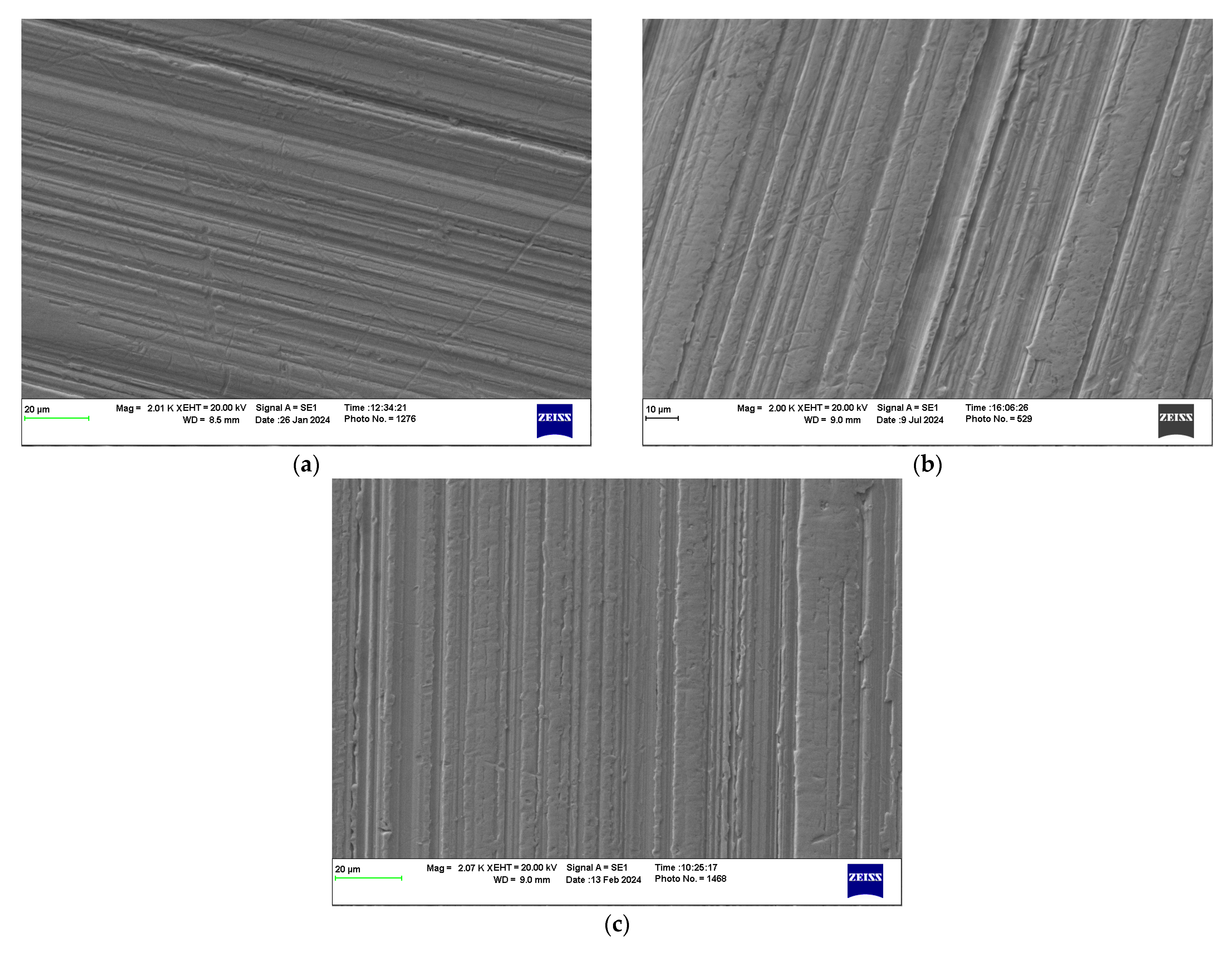
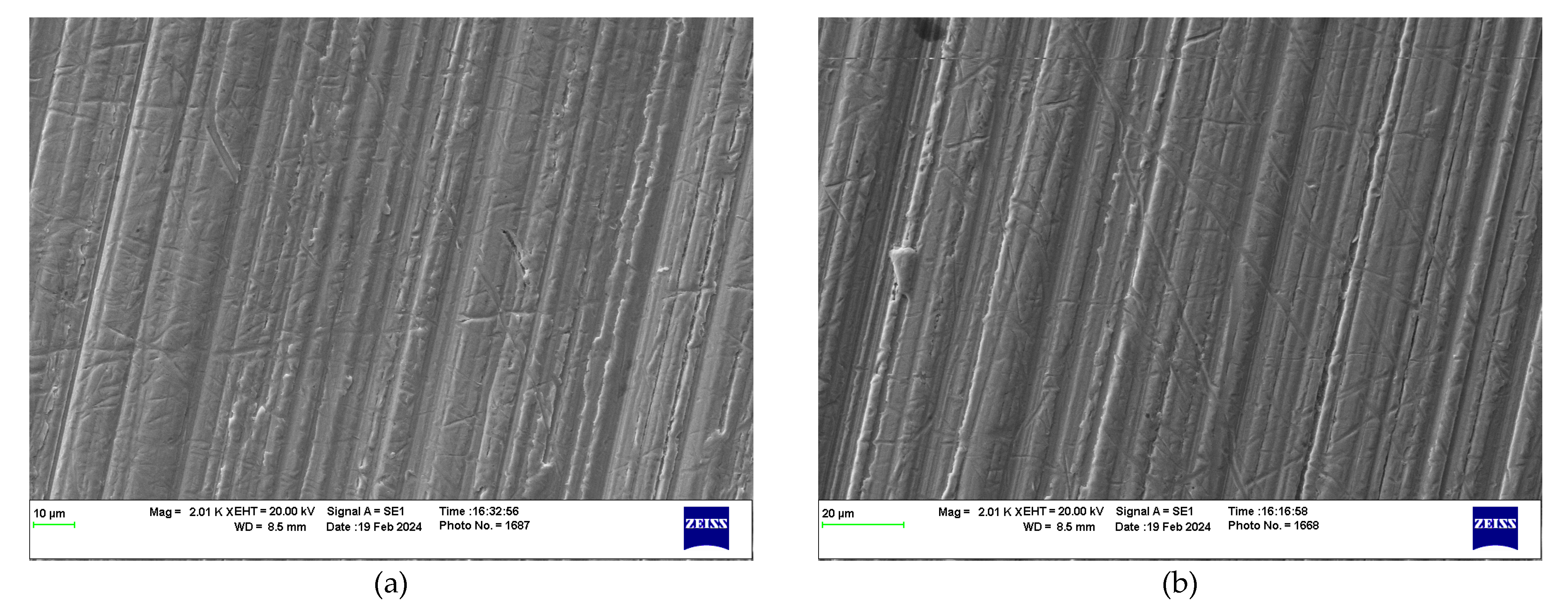
  • Little to no definitive electrical damage was present after the complete rotational or full revolution/cycle tests were conducted.
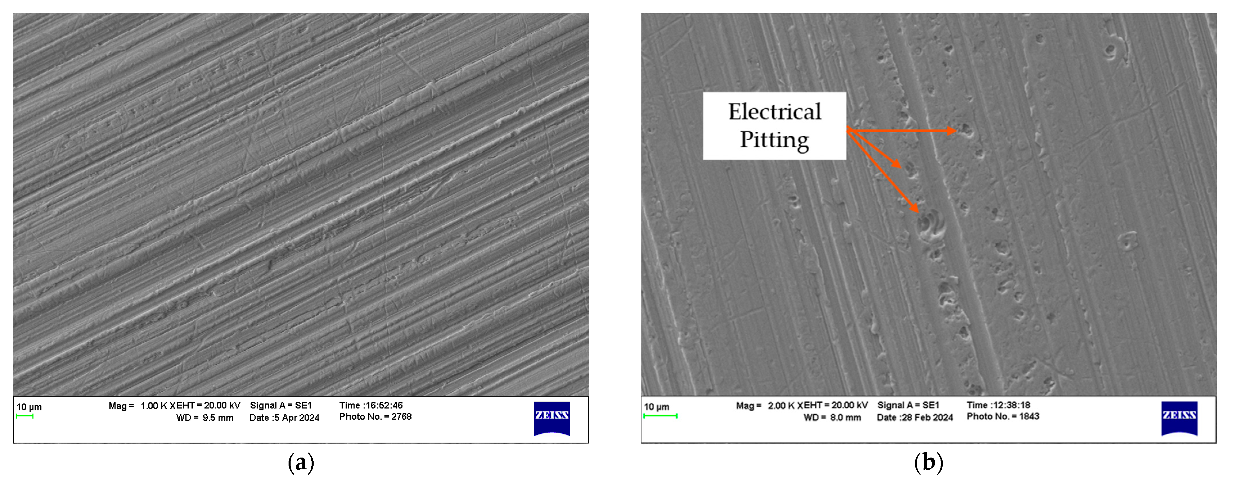
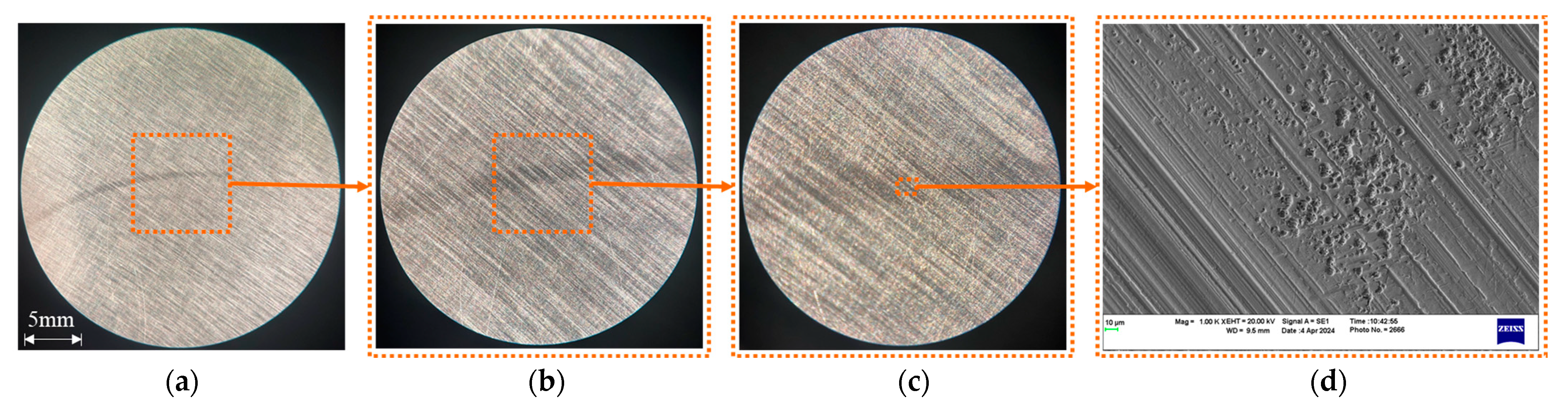
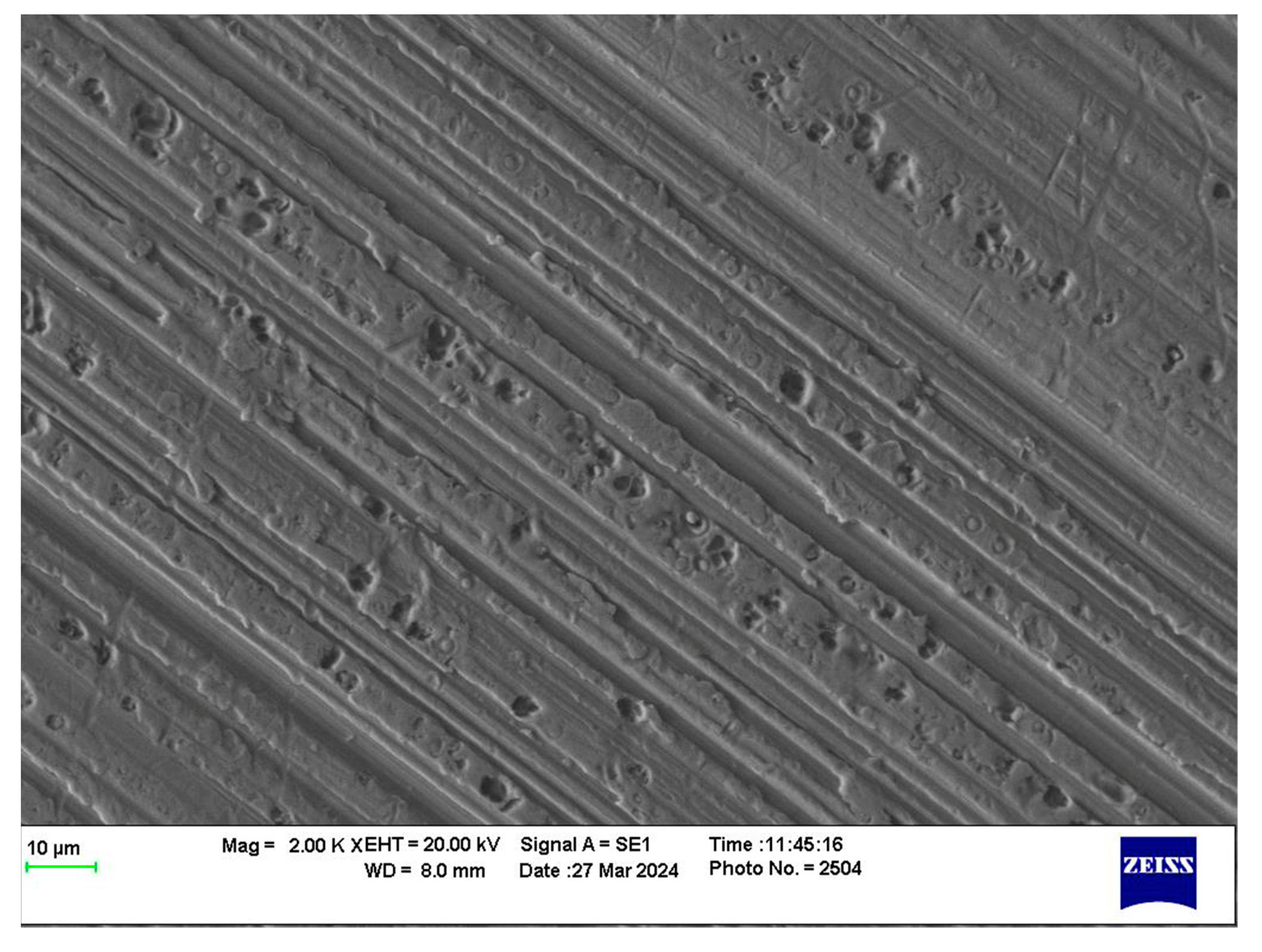
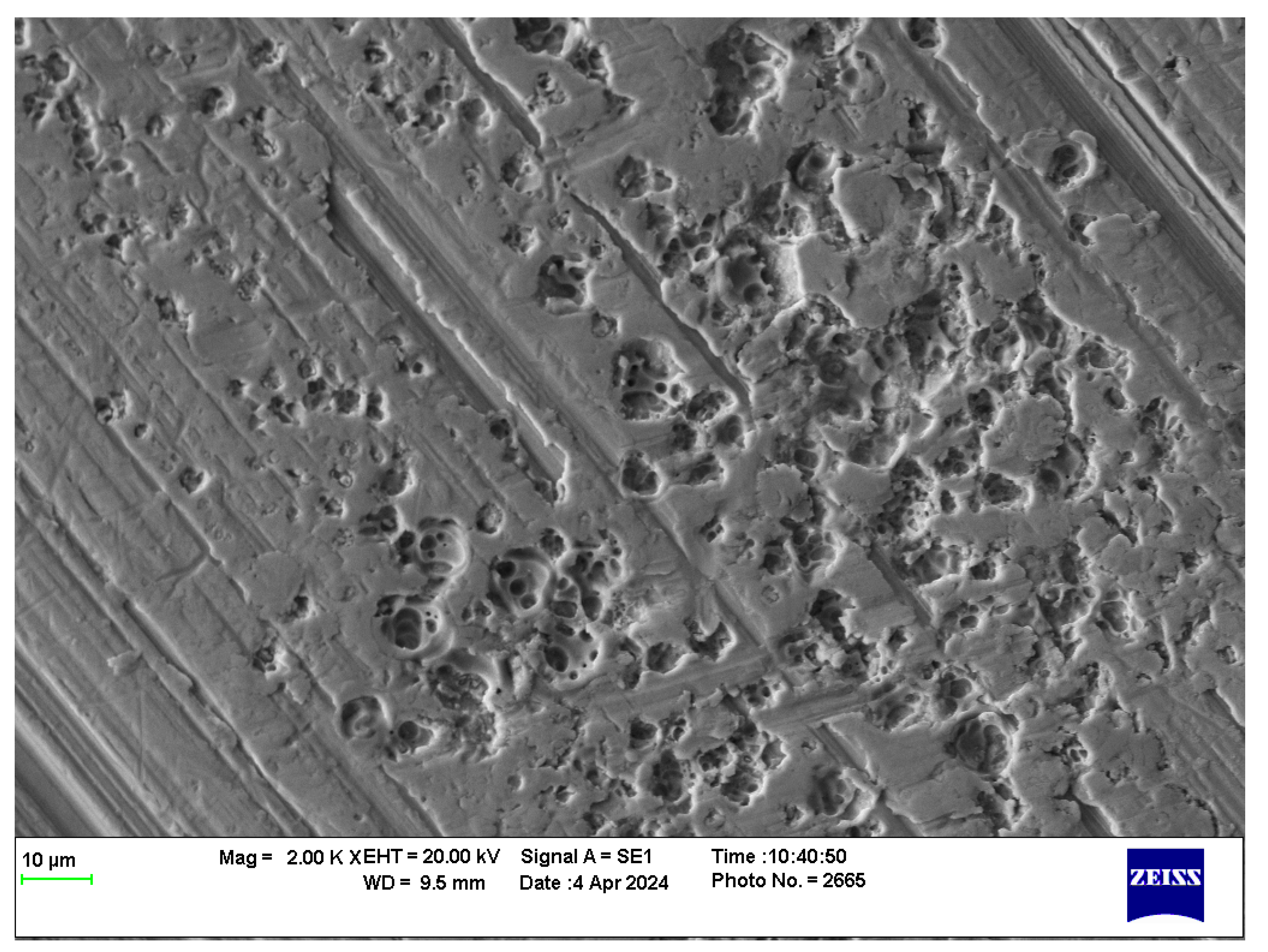
  • Significant pitting damage occurred during reciprocating tests with track lengths between 1 cm and 4 cm. Among these, the 2 cm track length showed the most severe damage.
  • The speed of the rolling element may affect the film thickness generated due to the EHL mechanism. Likewise, the thickness of the film affects the insulative and capacitive properties of the dielectric lubricant. Thin films are expected to pass charge easier than thicker films, which act as total dielectrics. Intermediate films are expected to be key for charge accumulation and discharge.
  • The varying track lengths for reciprocating tests have significant implications for the charge dissipation patterns. Charge may not be discharged over long distances and sustained motion in a single concentrated area. During start/stop conditions, the extended time at a single location allows for a more intense and destructive ablation. This suggests that more damage would be concentrated near the track ends of reciprocating tracks. This is supported by the pitting location that was captured in the SEM images. Vehicles that make frequent stops, such as delivery vehicles or commuter transportation, may be more susceptible to this damage given this effect.
  • The primary location of pitting along the asperity or roughness ridges reiterates the mechanism/model, suggesting that the pits are the remains of exploded asperities.
  • Evidence of thermal fatigue from cracking reiterates the high energy (heat) generated during the pit formation process. While the cracks are not attributed to surface fatigue, thermal expansion may result in surface fatigue or premature mechanical failure.
While this work provides a comprehensive look at the key conditions for electrically induced surface damage, additional testing is planned to fully understand the critical conditions for pitting damage and how grease chemistry plays a deciding role in damage resistance. The present tests fundamentally examined the conditions that attribute to pitting formation. Future work will address opportunities for improvement. Attention will be given to reproducing the complex loading in multi-element bearings, as the simplified testing in the current work neglects the extreme temperatures, vibrations, and environmental exposure that may affect real EV applications. Nonetheless, this study offers crucial insights into EIBD mechanisms, emphasizing the significance of comprehending the operational conditions that influence EIBD. This understanding can foster better design and maintenance practices, thereby enhancing the overall system efficiency and lifespan.

Author Contributions

Funding, Acquisition, Project Administration, R.L.J.; Conceptualization and Supervision, R.L.J. and G.M.; Methodology, Investigation, Formal Analysis, Visualization, and Writing—Original Draft Preparation, J.R.J.; Investigation, S.S.; All authors contributed to Writing—Review and Editing. All authors have read and agreed to the published version of the manuscript.

Funding

This research was funded by the National Lubricating Grease Institute (NLGI) Academic Outreach Research Grant. The first author was also awarded the Bob Jackson Award from the Independent Lubricant Manufacturers Association (ILMA).

Data Availability Statement

The raw data supporting the conclusions of this article will be made available by the authors on request.

Acknowledgments

The authors would like to recognize Paul Slade for his valuable consultation on arc propagation, Shell Oils for donating the tested grease, Bruker for donating the rolling element holder, and Chad Chichester from DuPont for his support as the NLGI project liaison.

Conflicts of Interest

The authors declare no conflicts of interest.

References

  1. IEA. Electric Car Sales, 2016–2023—Charts—Data & Statistics. Available online: https://www.iea.org/data-and-statistics/charts/electric-car-sales-2016-2023 (accessed on 2 October 2023).
  2. IEA. Global EV Outlook 2023—Analysis. Available online: https://www.iea.org/reports/global-ev-outlook-2023 (accessed on 3 October 2023).
  3. Hamidizadeh, S.; Alatawneh, N.; Chromik, R.R.; Lowther, D.A. Comparison of Different Demagnetization Models of Permanent Magnet in Machines for Electric Vehicle Application. IEEE Trans. Magn. 2016, 52, 1–4. [Google Scholar] [CrossRef]
  4. Sebastian, T. Temperature effects on torque production and efficiency of PM motors using NdFeB magnets. In Proceedings of the Conference Record of the 1993 IEEE Industry Applications Conference Twenty-Eighth IAS Annual Meeting, Toronto, ON, Canada, 2–8 October 1993; Volume 1, pp. 78–83. [Google Scholar] [CrossRef]
  5. Chen, Y.; Jha, S.; Raut, A.; Zhang, W.; Liang, H. Performance Characteristics of Lubricants in Electric and Hybrid Vehicles: A Review of Current and Future Needs. Front. Mech. Eng. 2020, 6, 571464. [Google Scholar] [CrossRef]
  6. Farfan-Cabrera, L.I. Tribology of electric vehicles: A review of critical components, current state and future improvement trends. Tribol. Int. 2019, 138, 473–486. [Google Scholar] [CrossRef]
  7. Lugt, P.M. Modern advancements in lubricating grease technology. Tribol. Int. 2016, 97, 467–477. [Google Scholar] [CrossRef]
  8. Hemanth, G.; Suresha, B. Hybrid and electric vehicle tribology: A review. Surf. Topogr. Metrol. Prop. 2021, 9, 043001. [Google Scholar] [CrossRef]
  9. Rezasoltani, A.; Khonsari, M.M. On Monitoring Physical and Chemical Degradation and Life Estimation Models for Lubricating Greases. Lubricants 2016, 4, 34. [Google Scholar] [CrossRef]
  10. Gurt, A.; Khonsari, M.M. Testing Grease Consistency. Lubricants 2021, 9, 14. [Google Scholar] [CrossRef]
  11. Gonda, A.; Capan, R.; Bechev, D.; Sauer, B. The Influence of Lubricant Conductivity on Bearing Currents in the Case of Rolling Bearing Greases. Lubricants 2019, 7, 108. [Google Scholar] [CrossRef]
  12. Huber, F.; Berwanger, J.; Polesya, S.; Mankovsky, S.; Ebert, H.; Giessibl, F.J. Chemical bond formation showing a transition from physisorption to chemisorption. Science 2019, 366, 235–238. [Google Scholar] [CrossRef]
  13. Xie, G.; Guo, D.; Luo, J. Lubrication under charged conditions. Tribol. Int. 2015, 84, 22–35. [Google Scholar] [CrossRef]
  14. Jackson, R.L.; Coker, A.B.; Tucker, Z.; Hossain, M.S.; Mills, G. An Investigation of Silver-Nanoparticle-Laden Lubricants for Electrical Contacts. IEEE Trans. Compon. Packag. Manuf. Technol. 2019, 9, 193–200. [Google Scholar] [CrossRef]
  15. Minami, I. Molecular Science of Lubricant Additives. Appl. Sci. 2017, 7, 445. [Google Scholar] [CrossRef]
  16. Jablonka, K.; Glovnea, R.; Bongaerts, J.; Morales-Espejel, G. The effect of the polarity of the lubricant upon capacitance measurements of EHD contacts. Tribol. Int. 2013, 61, 95–101. [Google Scholar] [CrossRef]
  17. Ahmed Abdalglil Mustafa, W.; Dassenoy, F.; Sarno, M.; Senatore, A. A review on potentials and challenges of nanolubricants as promising lubricants for electric vehicles. Lubr. Sci. 2022, 34, 1–29. [Google Scholar] [CrossRef]
  18. Scarlett, N.A. Paper 21: Use of Grease in Rolling Bearings. Proc. Inst. Mech. Eng. Conf. Proc. 1967, 182, 585–624. [Google Scholar] [CrossRef]
  19. Åström, H. Irregular film thickness fluctuations in elastohydrodynamic lubrication of a point contact lubricated with lubricating grease. Tribologia 1992, 11, 179–184. [Google Scholar]
  20. Cann, P.M.; Webster, M.N.; Doner, J.P.; Wikstrom, V.; Lugt, P. Grease Degradation in R0F Bearing Tests. Tribol. Trans. 2007, 50, 187–197. [Google Scholar] [CrossRef]
  21. Wang, J.; Guo, Z.; Hu, W.; Lu, H.; Li, J. Investigating the effects of base oil type on microstructure and tribological properties of polyurea grease. Tribol. Int. 2024, 194, 109573. [Google Scholar] [CrossRef]
  22. Zhang, X.; Glovnea, R. Grease film thickness measurement in rolling bearing contacts. Proc. Inst. Mech. Eng. Part J J. Eng. Tribol. 2021, 235, 1430–1439. [Google Scholar] [CrossRef]
  23. Cann, P.M.; Williamson, B.P.; Coy, R.C.; Spikes, H.A. The behaviour of greases in elastohydrodynamic contacts. J. Phys. Appl. Phys. 1992, 25, A124. [Google Scholar] [CrossRef]
  24. Farcas, F.; Gafitanu, M.D. Some influence parameters on greases lubricated rolling contacts service life. Wear 1999, 225–229, 1004–1010. [Google Scholar] [CrossRef]
  25. Åström, H.; Östensen, J.O.; Höglund, E. Lubricating Grease Replenishment in an Elastohydrodynamic Point Contact. J. Tribol. 1993, 115, 501–506. [Google Scholar] [CrossRef]
  26. Zhang, S.; Klinghart, B.; Jacobs, G.; von Goeldel, S.; König, F. Prediction of bleeding behavior and film thickness evolution in grease lubricated rolling contacts. Tribol. Int. 2024, 193, 109369. [Google Scholar] [CrossRef]
  27. Taycan, Taycan 4S, Turbo and Turbo S—The Battery—Porsche Taycan. Available online: https://media.porsche.com/mediakit/taycan/en/porsche-taycan/die-batterie (accessed on 16 October 2023).
  28. Model 3 Owner’s Manual. Available online: https://www.tesla.com/ownersmanual/model3/en_us/ (accessed on 16 October 2023).
  29. Hadden, T.; Jiang, J.W.; Bilgin, B.; Yang, Y.; Sathyan, A.; Dadkhah, H.; Emadi, A. A Review of Shaft Voltages and Bearing Currents in EV and HEV Motors. In Proceedings of the IECON 2016—42nd Annual Conference of the IEEE Industrial Electronics Society, Florence, Italy, 23–26 October 2016; pp. 1578–1583. [Google Scholar] [CrossRef]
  30. He, F.; Xie, G.; Luo, J. Electrical bearing failures in electric vehicles. Friction 2020, 8, 4–28. [Google Scholar] [CrossRef]
  31. Abu-Rub, H.; Bayhan, S.; Moinoddin, S.; Malinowski, M.; Guzinski, J. Medium-Voltage Drives: Challenges and existing technology. IEEE Power Electron. Mag. 2016, 3, 29–41. [Google Scholar] [CrossRef]
  32. Habibullah, M.; Lu, D.D.-C.; Xiao, D.; Rahman, M.F. Finite-State Predictive Torque Control of Induction Motor Supplied From a Three-Level NPC Voltage Source Inverter. IEEE Trans. Power Electron. 2017, 32, 479–489. [Google Scholar] [CrossRef]
  33. Cao Romero, J.A.; Reyes-Avendaño, J.; Soriano, J.; Farfan-Cabrera, L.; Erdemir, A. A Pin-on-Disc Study on the Electrified Sliding Wear of EVs Powertrain Gears; SAE International: Warrendale, PA, USA, 2022. [Google Scholar] [CrossRef]
  34. Amjad, S.; Neelakrishnan, S.; Rudramoorthy, R. Review of design considerations and technological challenges for successful development and deployment of plug-in hybrid electric vehicles. Renew. Sustain. Energy Rev. 2010, 14, 1104–1110. [Google Scholar] [CrossRef]
  35. Rind, S.; Ren, Y.; Jiang, L. Traction motors and speed estimation techniques for sensorless control of electric vehicles: A review. In Proceedings of the 2014 49th International Universities Power Engineering Conference (UPEC), Cluj-Napoca, Romania, 2–5 September 2014; pp. 1–6. [Google Scholar] [CrossRef]
  36. Shami, U.T.; Akagi, H. Identification and Discussion of the Origin of a Shaft End-to-End Voltage in an Inverter-Driven Motor. IEEE Trans. Power Electron. 2010, 25, 1615–1625. [Google Scholar] [CrossRef]
  37. Fišer, R.; Ferkolj, S. Magnetic field analysis of induction motor with rotor faults. COMPEL—Int. J. Comput. Math. Electr. Electron. Eng. 1998, 17, 206–211. [Google Scholar] [CrossRef]
  38. Asakura, Y.; Akagi, H. Mechanism of Shaft End-to-End Voltage Generation by Asymmetry in an Inverter-Driven Motor. Electr. Eng. Jpn. 2013, 185, 48–56. [Google Scholar] [CrossRef]
  39. Prashad, H. Investigation of damaged rolling-element bearings and deterioration of lubricants under the influence of electric fields. Wear 1994, 176, 151–161. [Google Scholar] [CrossRef]
  40. Zika, T.; Gebeshuber, I.C.; Buschbeck, F.; Preisinger, G.; Gröschl, M. Surface analysis on rolling bearings after exposure to defined electric stress. Proc. Inst. Mech. Eng. Part J J. Eng. Tribol. 2009, 223, 787–797. [Google Scholar] [CrossRef]
  41. Muetze, A.; Binder, A. Don’t lose your bearings. IEEE Ind. Appl. Mag. 2006, 12, 22–31. [Google Scholar] [CrossRef]
  42. Kudelina, K.; Asad, B.; Vaimann, T.; Belahcen, A.; Rassõlkin, A.; Kallaste, A.; Lukichev, D.V. Bearing Fault Analysis of BLDC Motor for Electric Scooter Application. Designs 2020, 4, 42. [Google Scholar] [CrossRef]
  43. Magdun, O.; Gemeinder, Y.; Binder, A. Investigation of influence of bearing load and bearing temperature on EDM bearing currents. In Proceedings of the 2010 IEEE Energy Conversion Congress and Exposition (ECCE), Atlanta, GA, USA, 12–16 September 2010; pp. 2733–2738. [Google Scholar] [CrossRef]
  44. Slade, P.G.; Taylor, E.D. Electrical breakdown in atmospheric air between closely spaced (0.2/spl mu/m-40/spl mu/m) electrical contacts. IEEE Trans. Compon. Packag. Technol. 2002, 25, 390–396. [Google Scholar] [CrossRef]
  45. Chen, Z.-K.; Sawa, K. Characteristics of Ag contact morphology in breaking arcs. Wear 1996, 199, 237–244. [Google Scholar] [CrossRef]
  46. Torres, J.-M.; Dhariwal, R.S. Electric field breakdown at micrometre separations. Nanotechnology 1999, 10, 102. [Google Scholar] [CrossRef]
  47. Van Rensselar, J. The Tribology of Electric Vehicles. Tribol. Lubr. Technol. 2019, 75, 34–44. [Google Scholar]
  48. Liu, Z.; Zhang, L. A review of failure modes, condition monitoring and fault diagnosis methods for large-scale wind turbine bearings. Measurement 2020, 149, 107002. [Google Scholar] [CrossRef]
  49. Walther, H.C.; Holub, R.A. Lubrication of electric motors as defined by IEEE standard 841-2009, shortcomings and potential improvement opportunities. In Proceedings of the 2014 IEEE Petroleum and Chemical Industry Technical Conference (PCIC), San Francisco, CA, USA, 8–10 September 2014; pp. 91–98. [Google Scholar] [CrossRef]
  50. Boškoski, P.; Petrovčič, J.; Musizza, B.; Juričić, Đ. Detection of lubrication starved bearings in electrical motors by means of vibration analysis. Tribol. Int. 2010, 43, 1683–1692. [Google Scholar] [CrossRef]
  51. Bond, S.; Jackson, R.L.; Mills, G. The influence of various grease compositions and silver nanoparticle additives on electrically induced rolling-element bearing damage. Friction 2024, 12, 796–811. [Google Scholar] [CrossRef]
  52. Bor-Jenq, W.; Nannaji, S.; Ernest, R. Static-gap, single-spark erosion of Ag-CdO and pure metal electrodes. Wear 1992, 157, 31–49. [Google Scholar] [CrossRef]
  53. Chatterton, S.; Pennacchi, P.; Vania, A. Electrical pitting of tilting-pad thrust bearings: Modelling and experimental evidence. Tribol. Int. 2016, 103, 475–486. [Google Scholar] [CrossRef]
  54. Graf, S.; Koch, O.; Sauer, B. Influence of Parasitic Electric Currents on an Exemplary Mineral-Oil-Based Lubricant and the Raceway Surfaces of Thrust Bearings. Lubricants 2023, 11, 313. [Google Scholar] [CrossRef]
  55. Farfan-Cabrera, L.I.; Cao-Romero-Gallegos, J.A.; Lee, S.; Komurlu, M.U.; Erdemir, A. Tribological behavior of H-DLC and H-free DLC coatings on bearing materials under the influence of DC electric current discharges. Wear 2023, 522, 204709. [Google Scholar] [CrossRef]
  56. Liu, W. The prevalent motor bearing premature failures due to the high frequency electric current passage. Eng. Fail. Anal. 2014, 45, 118–127. [Google Scholar] [CrossRef]
  57. Raadnui, S.; Kleesuwan, S. Electrical pitting wear debris analysis of grease-lubricated rolling element bearings. Wear 2011, 271, 1707–1718. [Google Scholar] [CrossRef]
  58. Robles, E.; Matallana, A.; Aretxabaleta, I.; Andreu, J.; Fernández, M.; Martín, J.L. The role of power device technology in the electric vehicle powertrain. Int. J. Energy Res. 2022, 46, 22222–22265. [Google Scholar] [CrossRef]
  59. Suzumura, J. Prevention of Electrical Pitting on Rolling Bearings by Electrically Conductive Grease. Q. Rep. RTRI 2016, 57, 42–47. [Google Scholar] [CrossRef]
  60. Sanchez Garrido, D.; Leventini, S.; Martini, A. Effect of Temperature and Surface Roughness on the Tribological Behavior of Electric Motor Greases for Hybrid Bearing Materials. Lubricants 2021, 9, 59. [Google Scholar] [CrossRef]
  61. Graf, S.; Werner, M.; Koch, O.; Götz, S.; Sauer, B. Breakdown voltages in thrust bearings: Behavior and Measurement. Tribol. Trans. 2023, 66, 488–496. [Google Scholar] [CrossRef]
  62. García Tuero, A.; Rivera, N.; Rodríguez, E.; Fernández-González, A.; Viesca, J.L.; Hernández Battez, A. Influence of Additives Concentration on the Electrical Properties and the Tribological Behaviour of Three Automatic Transmission Fluids. Lubricants 2022, 10, 276. [Google Scholar] [CrossRef]
  63. Flores-Torres, S.; Holt, D.G.L.; Carey, J.T. Method for Preventing or Minimizing Electrostatic Discharge and Dielectric Breakdown in Electric Vehicle Powertrains. US20180100120A1, 12 April 2018. Available online: https://patents.google.com/patent/US20180100120A1/en (accessed on 8 November 2023).
  64. Crilly, L.; Jackson, R.L.; Mills, G.; Bond, S.; Bhargava, S. An Exploration of the Friction, Wear, and Electrical Effects of Nanoparticle Enhanced and Conventional Lubricants. IEEE Trans. Compon. Packag. Manuf. Technol. 2022, 12, 1757–1770. [Google Scholar] [CrossRef]
  65. Noguchi, S.; Kakinuma, S.; Kanada, T. Measurement of Direct Current Voltage Causing Electrical Pitting. J. Adv. Mech. Des. Syst. Manuf. 2010, 4, 1084–1094. [Google Scholar] [CrossRef]
  66. Slade, P.G. The Arc and Interruption. In Electrical Contacts; CRC Press: Boca Raton, FL, USA, 1999; pp. 433–486. [Google Scholar]
  67. Schwirzke, F.; Hallal, M.P.; Maruyama, X.K. Onset of breakdown and formation of cathode spots. IEEE Trans. Plasma Sci. 1993, 21, 410–415. [Google Scholar] [CrossRef]
  68. Morris, S.A.; Leighton, M.; Morris, N.J. Electrical Field Strength in Rough Infinite Line Contact Elastohydrodynamic Conjunctions. Lubricants 2022, 10, 87. [Google Scholar] [CrossRef]
Figure 1. Proposed pit formation model: (a) charge accumulation near asperities; (b) electron emission toward substrate plate in areas of intermediate film thickness; (c) asperity heating; (d) explosive arc propagation and molten material transfer; (e) presence of suspended debris and electrical pitting.
Lubricants 12 00268 g001
Figure 2. SEM images of test samples: (a) untested sample surface; (b) electrical pitting (mineral-based grease, 2 cm track length, 5400 s).
Lubricants 12 00268 g002
Figure 3. 2 cm frosted arc track from rolling ball-on-disk tests: (a) microscope view at 1×; (b) microscope view at 3×; (c) microscope view at 6×; (d) SEM image of electrical pitting from 2 cm reciprocating tests over 5400 s with mineral-based grease.
Lubricants 12 00268 g003
Figure 4. A 3D-printed electrical contact holder and test set-up for rolling ball-on-disk tests.
Lubricants 12 00268 g004
Figure 5. Idealized electrical circuit for the rolling ball-on-disk tests.
Lubricants 12 00268 g005
Figure 6. SEM images of test samples after full rotational tests: (a) high-speed (1 m/s (523.25 RPM), 5400 s); (b) moderate-speed (0.1 m/s (523.25 RPM), 5400 s); (c) low-speed (0.01 m/s (5.2325 RPM), 5400 s).
Lubricants 12 00268 g006
Figure 7. SEM images of test samples after full rotation/cycle tests: (a) 10 Rev./Cycle (0.01 m/s (3.64 RPM), 7200 s); (b) 1 Rev./Cycle (0.01 m/s (4.46 RPM), 14,400 s).
Lubricants 12 00268 g007
Figure 8. Relationship between test conditions and observed damage at different track lengths: (a) observed damage vs. average voltage; (b) observed damage vs. number of directional changes; (c) observed damage vs. linear speed.
Lubricants 12 00268 g008
Figure 9. SEM images of pitting concentrated along highlighted asperity ridgelines (2 cm track length, 5400 s).
Lubricants 12 00268 g009
Figure 10. SEM images of pitting irregularity (2 cm track length, 5400 s).
Lubricants 12 00268 g010
Figure 11. SEM images of pit propagation from center of pits: (a) deep-cavity pit at 8 k magnification (2 cm track length, 5400 s); (b) wide flat pit at 8 k magnification (2 cm track length, 5400 s).
Lubricants 12 00268 g011
Table 1. Relationship between test conditions and observed damage at different track lengths.
Track Length
[cm]
Observed Damage
[%]
No. of Directional Changes [#]Max. Linear Speed [m/s]Avg. Voltage
[V]
10.656336171.203 × 10−20.7941
25.12925511.761 × 10−21.360
31.31520762.172 × 10−20.7950
40.116717942.530 × 10−21.417
Disclaimer/Publisher’s Note: The statements, opinions and data contained in all publications are solely those of the individual author(s) and contributor(s) and not of MDPI and/or the editor(s). MDPI and/or the editor(s) disclaim responsibility for any injury to people or property resulting from any ideas, methods, instructions or products referred to in the content.

