Article

Investigation of Failure Mechanisms in Oil-Lubricated Rolling Bearings under Small Oscillating Movements: Experimental Results, Analysis and Comparison with Theoretical Models

Department of Mechanical Engineering, Friedrich-Alexander-Universität Erlangen-Nürnberg (FAU), Engineering Design, Martensstraße 9, 91058 Erlangen, Germany
*
Author to whom correspondence should be addressed.
Lubricants 2024, 12(8), 271; https://doi.org/10.3390/lubricants12080271
Submission received: 4 June 2024 / Revised: 21 July 2024 / Accepted: 26 July 2024 / Published: 29 July 2024
(This article belongs to the Special Issue Tribology in Germany: Latest Research and Development)

Abstract

:
Bearing life calculation is a well-researched and standardized topic for rotating operation conditions. However, there is still no validated and standardized calculation for oscillating operation, only different calculation approaches. Due to the increasing number of oscillating rolling bearings, for example, in wind turbines, industrial robots, or 3D printers, it is becoming more and more important to validate one of these approaches or to formulate a new one. In order to achieve this goal, the damage mechanisms for oscillating operating conditions must first be analyzed in more detail by means of experimental investigations. The open question is whether fatigue is the relevant damage mechanism or whether wear damage, such as fretting corrosion or false brinelling, dominates. The present work therefore shows under which oscillation angle and frequency fatigue occur in oil-lubricated cylindrical roller bearings.

1. Introduction

1.1. Motivation and State-of-the-Art

There are many applications where rolling bearings are used in oscillating movements. The most prominent examples are pitch bearings in wind turbines [1,2] and joints in industrial robots. However, bearings are also used in oscillating movements on a smaller scale, for example, in 3D printers.
Although there have been more than 1000 tests with oscillating movements since 1964, there is still no standardized method for calculating the life of rolling bearings under oscillating movements, only different calculation approaches [3,4]. The best-known current approaches are those of Harris [5,6] and Houpert [7]. Another possibility is to convert the oscillating movement into a continuous rotary motion and use the basic rating life equation according to DIN ISO 281 [8]. The different approaches are briefly described below. For a deeper insight into the various calculation approaches, the work of Menck is recommended [9].
All calculation approaches are based on the standardized rating life calculation for continuous rotary motion according to DIN ISO 281 (see Equation (1)). The relationship between dynamic capacity C and equivalent dynamic load P is maintained, but the oscillating movement is taken into account in different ways. All approaches use the oscillation angle φ, which is defined as the angle between the starting point and the return point of the oscillatory movement. In addition, all approaches use the life exponent p in their respective rating life equation LOsc, where p = 3 for ball bearings and p = 10/3 for roller bearings, as defined in DIN ISO 281:
L 10 = C P p

1.1.1. Approach by HarrisMethod 1

Harris introduces a modified load PRE that depends on the oscillation angle φ and the life exponent pH, with pH = 3 for point contact (ball bearings) and pH = 4 for line contact (roller bearings) [5]:
P RE = φ 180 ° 1 p H P
PRE can be inserted into the basic rating life equation LOsc and gives the number of oscillations in 106 cycles:
L O s c = C P R E p

1.1.2. Approach by Harris and RumbargerMethod 2

A more recent approach by Harris and Rumbarger, specifically aimed at wind turbines, introduces a modified load rating COsc and a critical oscillation angle φCRIT [6]. In this context, φCRIT is the oscillation angle at which the loaded raceway areas touch but do not intersect. As the following equations Equations (4) and (5) indicate, φCRIT depends on the number of rolling elements Z, the contact angle α, the rolling element diameter Dw, and the pitch diameter Dpw. In Equation (4), the upper sign (+) refers to the inner raceway and the lower sign (−) refers to the outer raceway:
φ crit = 720 ° Z ( 1 ± γ )
γ = D w cos ( α ) D pw
For oscillation angles φ > φCRIT, the calculation of COsc is expressed as follows:
C Osc = 180 ° φ 1 p H C
In Equation (6), the life exponent pH is, again, pH = 4 for roller bearings and pH = 3 for ball bearings.
For φ < φCRIT, the calculation of COsc is differentiated for ball bearings (see Equation (7)) and roller bearings (see Equation (8)):
C Osc = 180 ° φ 3 10 Z 0.033 C
C Osc = 180 ° φ 2 9 Z 0.028 C
Again, COsc can be inserted into the basic rating life equation, which gives the number of oscillations LOsc in 106 cycles:
L Osc = C Osc P p

1.1.3. Approach by Houpert

Houpert changes neither the load rating C nor the load P, but introduces the oscillation factor AOsc [7]:
L Osc = A Osc C P p
The factor AOsc depends on the load zone parameter e and the oscillation angle φ. However, the calculation is only valid for angles greater than 2π/Z and is complex due to the calculation of the load zone parameter. For more information on calculating the load zone parameter e and values for AOsc for oscillation angles between 10° and 90°, see [7]. Recently, Houpert and Menck [10] corrected an error in the original calculation approach that had come simultaneously to the attention of Menck as well as Breslau and Schlecht [11] in 2020.

1.1.4. Approach with an Equivalent Speed n

Another approach, which can also be found in the catalogs of various rolling bearing manufacturers, uses the oscillation angle φ and the oscillation frequency nOsc to form an equivalent speed n that can be used in the basic rating life calculation according to DIN ISO 281:
n = n Osc φ 180 °
All calculation approaches based on the basic rating life calculation according to DIN ISO 281 can be modified using the coefficient aISO to calculate the extended rating life. However, the use of this calculation for oscillating movements is controversial because lubrication cannot be guaranteed, especially with small oscillating movements and the use of grease. As a result, the parameter for the lubrication condition (viscosity ratio) κ is less than 0.1 under the usual operating conditions for oscillating movements [6]. According to DIN ISO 281, this means that the calculation of the aISO factor is no longer valid [8].

1.2. Research Objective of This Paper

It has been shown that there are a large number of applications in which rolling bearings are used under oscillating movements. However, there is no validated calculation method, only various approaches, some of which differ considerably in their results. Most of the current work focuses on the occurrence of wear during small oscillating movements or vibrations. Particular attention is paid to the occurrence of false brinelling and stall marks and their prevention by the use of suitable lubricants [12,13]. Studies on fatigue and oscillating movements are rare and are limited to relatively large oscillation angles [14].
The research objective of this paper is therefore to investigate whether fatigue is possible with small oscillating movements and whether the calculation approaches presented above are valid at all. For this reason, rating life tests are carried out for cylindrical roller bearings under oil lubrication to determine if fatigue occurs as a failure mechanism.

2. Materials and Methods

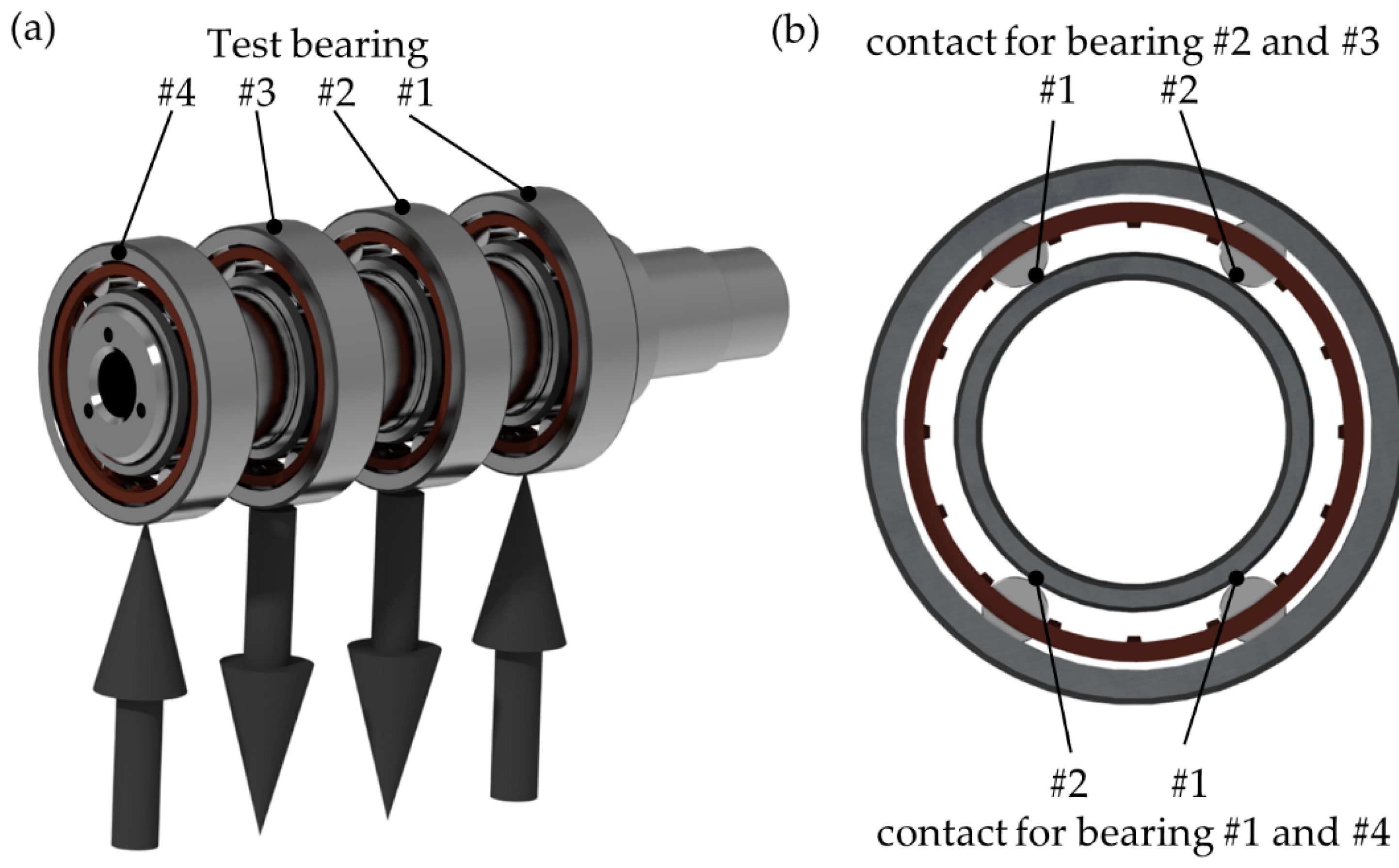
2.1. Experimental Setup

The Chair of Engineering Design has built a test rig as part of an FVA project to investigate the fatigue life of rolling bearings under small oscillating movements [15]. The WSBP (Figure 1) is a custom test rig that allows four radial bearings to be tested simultaneously. Cylindrical roller bearings (NU210) or deep groove ball bearings (6210) can be used as test bearings.
The test shaft (see Figure 2a) is directly driven by a synchronous motor. Continuous rotation or oscillation angles ranging from 0.1° to 360° are possible with an oscillation frequency of up to 20 Hz. A worm gear screw jack generates the radial test load up to a maximum of 60 kN. A recirculating oil lubrication system continuously supplies the bearings with oil. At eight lubrication points between the bearings, each of the nozzle’s four holes simultaneously lubricates the contacts between the outer ring and rolling element, as well as between the inner ring and rolling element.
Bearing and oil temperature, oil flow, and radial force can be measured and recorded. In addition, an optical measuring system can measure slippage that might occur in the outer test bearing #4.
The number of rolling elements in each test bearing is reduced to four (see Figure 2b). They are arranged symmetrically, whereby only the two rolling elements at the bottom or the top are loaded according to the radial load for each test bearing. The remaining two rolling elements serve purely to guide the cage. This setup has several advantages: The force that is required to achieve the intended contact pressure is reduced; moreover, even at larger oscillation angles, the contact areas of adjacent contacts do not intersect, which significantly improves the possibility of evaluating and analyzing the damage.

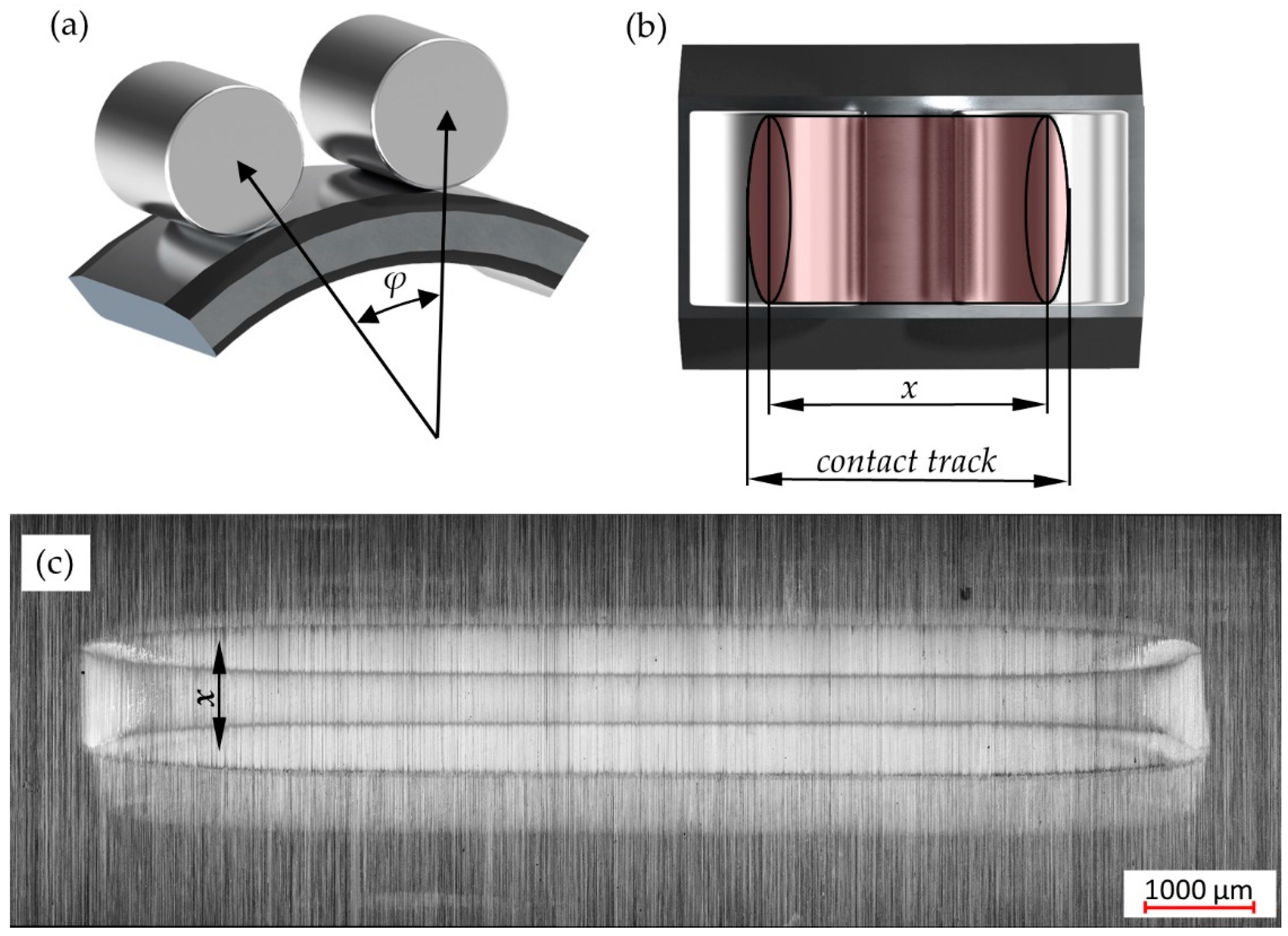
2.2. Test Procedure, Plan, and Analysis

Screening tests with 100,000 oscillation cycles have shown that small oscillation angles in the range of 2° to 5° at oscillation frequencies of 5 Hz to 15 Hz show little wear, so fatigue is possible at a later stage [16]. For this reason, the oscillation angle φ was set to 3° and the oscillation frequency to 10 Hz for the rating life tests performed in this work. Cylindrical roller bearings (NU 210) by two different manufacturers were used. The Hertzian contact pressure at the inner ring-roller contact was set to 3000 MPa in order to minimize test run times. The shutdown criteria for the fatigue life test is the formation of a spalling. These can be detected from a certain size via the deviation of the actual oscillation movement.
Prior to testing, unneeded rolling elements are removed and the bearings are cleaned by hand with isopropanol. All tests are performed with FVA 3 oil at 30 °C at a total flow rate of 4 L/min (0.5 L/min for each of the eight lubrication points). After testing, a laser scanning microscope (Keyence VK-X200, Keyence Deutschland GmbH, Neu-Isenburg, Germany) is used to evaluate and qualitatively assess the contact zone/track (see Figure 3c).
The aim was to generate as many failures as possible due to fatigue and to compare the experimental rating life with the theoretical rating life. In addition, it should be clarified whether “classical” sub-surface or surface-initiated fatigue occurs.
Table 1 shows the characteristics of the test bearings and the test parameters. For the purpose of life calculation, each contact is considered as an individual bearing. This is possible because the individual contacts do not intersect during the small oscillating movement. The advantage of this is that with the four test bearings, eight contacts can be considered individually in the life calculation. In addition, the dimensionless x/2b ratio is specified, which indicates the oscillation path x in relation to the semi-minor half-axis b of the contact ellipse. The ratio facilitates the comparison of different bearing types and sizes.
Figure 3 shows the oscillation angle φ and the oscillation path x on the raceway resulting from the oscillation movement as a rendering. Figure 3c shows a typical contact track on the actual raceway. It consists of the two reversal points of the oscillation movements, which correspond to the shape of the Hertzian contact ellipse.

3. Results

A total of eight rating life tests were performed, in which a total of over 135 million oscillation cycles were completed. This corresponds to a pure test duration of 157 days. In addition, further tests were carried out with cylindrical roller bearings at a lower contact pressure and with deep groove ball bearings to validate the results. In total, more than 289 million oscillation cycles were performed.
Table 2 lists all the test runs, including the bearing type (cylindrical roller bearing, CRB, or deep groove ball bearing, DGB), the Hertzian pressure at the inner ring-roller contact, and the number of oscillation cycles until failure. It is also indicated on which bearing inner or outer ring the damage has occurred.
It should be noted that the test run was shut down as soon as damage was detected. Damage is detected via the drive motor control: As soon as the actual oscillation angle deviates from the specified oscillation angle and an increase in the frictional torque occurs at the same time, damage has occurred. While in theory, all eight contacts could fail at the same time, in reality, damage always occurs on one of the eight contacts first. Due to the subsequent shutdown, only one of the eight contacts failed in the following tests.

3.1. Rating Life Tests RV 1 to SV 3

Rolling bearings from two different manufacturers were used for the rating life tests. In principle, the observed failures are very similar for both manufacturers, though the location of the failures differs. While the failure is mainly localized on the outer ring for manufacturer A, it is mainly located on the inner ring for manufacturer B.
In tests RV 1, RV 2, RV 3, and RV 5, bearing 3 failed due to a spalling at contact 1 of the outer ring. In test RV 4, bearing 4 failed at contact 1 of the outer ring due to a spalling.
In tests SV 1 and SV 3, a spalling occurred at the inner ring contact 2 of bearing 2. Test SV 2 failed due to a spalling at the inner ring contact 1 of bearing 3.
The location and shape of the observed spalling are similar for all tests. The spalling is located at the outer end of the contact track in all tests (see Figure 4). The spalling runs at an angle of approx. 45° from the surface into the depth (orthogonal to the oscillation direction). The deepest point is characterized by a course of almost 90° to the surface, which can be observed in particular in the spalling on the inner ring. In addition, a kind of elevation can be observed in the center of the spalling, which corresponds to the center of the oscillation movement. This elevation can be measured, but is also very easy to recognize optically (see Figure 5).
The remaining contact track shows a strong reddish discoloration due to hematite formation as well as a bluish tribological layer formation due to metal particles and higher local pressure. It should be noted here that the spalling is not usually detected immediately, but only shuts down approx. 500,000 cycles later.
The shape and location of the spalling can be explained by a surface-initiated crack formation that occurs at the outer end of the contact track. Cyclic loading causes the crack to grow in depth, resulting in the observed spalling. This can also be confirmed by crack formation in this and other tests in which cracks were observed at the transition from the contact track to the unloaded raceway (see Figure 6).
Looking at tests RV 1, RV 2, RV 3, and RV 5, it is noticeable that the fault occurs on the same contact, in bearing 3 on contact 1. Basically, the probability of a particular contact failing is 1/8, as there are a total of 8 contacts that can fail, and the first failure is followed by a shutdown. At first sight, it seems very unlikely for all four attempts to fail on the same contact, though possible explanations can be given. One of them is the design of the test rig. As bearings 2 and 3 are used to apply the force, those will definitely receive the full test load. Bearing 1, on the other hand, is positioned next to the motor bearing, raising the possibility that the motor bearing receives a fraction of the test load. In addition, the contacts of bearings 2 and 3 are at the upper position, so that they are lubricated only by the injected oil, while the contacts of bearings 1 and 4 are located at the bottom position, where an oil bath is formed.
Additional tests must therefore be carried out to check and verify that the occurring failure mechanism is indeed fatigue damage and not a localized exceeding of the yield point due to tilting of the rolling elements or deflection of the shaft. For this purpose, tests with deep groove ball bearings and tests with cylindrical roller bearings were carried out at lower Hertzian pressures.

3.2. Check #1 with Deep Groove Ball Bearings: Is Tilting the Cause of the Damage?

A simple verification was carried out to rule out possible tilting of the rolling elements. Deep groove ball bearings were used as test bearings, where tilting of the rolling elements is not possible due to their design. The tests were carried out with identical test parameters (oscillation frequency, oscillation angle, and Hertzian pressure). Several tests were carried out, whereby a random shutdown occurred in one test after approx. 15 million oscillation cycles. This shutdown proved to be a stroke of luck, as crack formation and the start of crack propagation could be observed in its initial stage (see Figure 7).
Of particular interest is the location of the crack formation, which is located directly at the transition from the contact track to the unloaded raceway.
This suggests that a similar damage mechanism can also be observed in deep groove ball bearings, as has already been observed in cylindrical roller bearings. As the failure was again on one of the two center bearings, it is necessary to ascertain whether the radial bearing test rig design results in a significantly increased test load on the center bearings, which may lead to premature non-fatigue damage. Additional tests were performed with a reduced contact pressure to address this concern.

3.3. Check #2: Is the Damage Still Present at Lower Hertzian Pressures?

In these tests, the Hertzian pressure in the inner ring-rolling element contact was set at 2500 MPa. The lower contact pressure results in a significantly longer theoretical rating life and also a significantly longer actual test rating life. A total of four tests were performed. Unfortunately, three out of four tests had to be canceled before any damage occurred, due to a failure of the motor bearing or a power failure at the building as a result of unannounced maintenance work. Regrettably, a restart at the identical contact point is not possible on the test bench due to its design.
As a result, there was only one test, which ran until it failed due to a spalling at bearing 1 contact 1 on the outer ring. This is particularly interesting, as the bearings from this manufacturer have only ever failed on the inner ring and there is a lower pressure of approx. 2150 MPa on the outer ring. The combination of the lower pressure and the position on the outer ring supports the assumption that this is a fatigue failure, rather than a different type of failure due to a localized increase in stress.

4. Discussion

The results show that fatigue can occur as a failure mode for rolling bearings under small oscillating movements. This was demonstrated for both line and point contacts at a pressure of 3000 MPa and an oscillation angle of 3° at an oscillation frequency of 10 Hz. It should be noted that these are oil-lubricated bearings.
To compare the theoretically calculated rating life with the actual rating life, the actual rating life must first be determined. For this purpose, the experimental rating life B10 is calculated for a 10% probability of failure using the failure times of the eight rating life tests (RV 1-5 and SV 1-3) and a 2-parametric Weibull distribution. This results in an experimental rating life of B10 = 16.99 × 10⁶ oscillation cycles (see Figure 8).
For a conservative estimate of the theoretical rating life, the calculation model that produces the highest rating life is used, in this case, the Approach with an equivalent speed n. This results in a rating life of L10 = 14.03 × 10⁶ oscillation cycles for an oscillation angle of 3°. As a further part of the conservative estimate, only the nominal rating life is calculated, as the aISO factor (aISO = 0.2 for the operating conditions present here) would only lead to a further reduction in the theoretical rating life.
The results show that the experimental rating life B10 determined in the test exceeds the theoretical rating life L10. Thus, with good lubrication conditions and a sufficiently large oscillation angle, a conservative estimation of the service life is possible using the calculation of the theoretical service life with the existing calculation approaches for cylindrical rolling bearings.
The accumulation of failures in test bearing 3 is striking. However, the validation tests demonstrated that these failures were always due to fatigue and not a localized exceeding of the yield point. One potential explanation for the number of failures is that the load on test bearing 3 is greater than on the other test bearings, which increases the probability of failure due to fatigue damage. This is not a critical issue, as the theoretical rating life would be reduced if the higher load were taken into account. Consequently, the experimentally determined rating life is still higher than the theoretical rating life.
The tests have therefore shown that fatigue is indeed occurring. However, it has not yet been conclusively clarified whether it is surface-initiated or classic sub-surface fatigue. The results indicate that the cracks are surface-induced and originate directly in the transition from the contact track to the unaffected part of the track. Unfortunately, an evaluation of various microsection analyses has not yet been successful, so this is still a hypothesis that needs to be finally verified with FIB sections or other methods. This should be the focus of further work.

Author Contributions

Conceptualization, methodology, validation, writing—original draft preparation, F.H.; writing—review and editing, M.B.; supervision, M.B. and S.W. All authors have read and agreed to the published version of the manuscript.

Funding

The test rig WSBP was funded by the Forschungsvereinigung Antriebstechnik e.V., project 824 I (IGF 19915 N). The remaining research received no external funding.

Data Availability Statement

For insights into in-depth data, e.g., test data, etc., please contact the corresponding author.

Acknowledgments

We acknowledge the support of the students Alexandra Neumann, Louis Römert, Jonas Ruhl, and Luzia Scheper for the conduct and evaluation of the experiments.

Conflicts of Interest

The authors declare no conflicts of interest.

References

  1. Schwack, F.; Halmos, F.; Stammler, M.; Poll, G.; Glavatskih, S. Wear in wind turbine pitch bearings—A comparative design study. Wind Energy 2021, 25, 700–718. [Google Scholar] [CrossRef]
  2. Behnke, K.; Schleich, F. Exploring limiting factors of wear in pitch bearings of wind turbines with real-scale tests. Wind Energy Sci. 2023, 8, 289–301. [Google Scholar] [CrossRef]
  3. Tawresey, J.S.; Shugarts, W.W. An Experimental Investigation of the Fatigue Life and Limit Load Characteristics of Needle Roller Bearings Under Oscillating Load Conditions. Available online: https://apps.dtic.mil/sti/citations/AD0437467 (accessed on 30 April 2024).
  4. Rumbarger, J.H.; Jones, A.B. Dynamic Capacity of Oscillating Rolling Element Bearings. J. Lubr. Tech. 1968, 90, 130–138. [Google Scholar] [CrossRef]
  5. Harris, T.A.; Kotzalas, M.N. Rolling Bearing Analysis. In Essential Concepts of Bearing Technology, 5th ed.; CRC Press: Boca Raton, FL, USA, 2007. [Google Scholar]
  6. Harris, T.A.; Rumbarger, J.H.; Butterfield, C.P. Wind Turbine Design Guideline DG03: Yaw and Pitch Rolling Bearing Life; Technical Report NREL/TP-500-42362; NREL: Golden, CO, USA, 2009. [Google Scholar] [CrossRef]
  7. Houpert, L. Bearing Life Calculation in Oscillatory Applications. Tribol. Trans. 1999, 42, 136–143. [Google Scholar]
  8. DIN ISO 281; Wälzlager—Dynamische Tragzahlen und nominelle Lebensdauer. Beuth: Berlin, Germany, 2010.
  9. Menck, O.; Stammler, M. Review of rolling contact fatigue life calculation for oscillating bearings and application-dependent recommendations for use. WES 2024, 9, 777–789. [Google Scholar] [CrossRef]
  10. Houpert, L.; Menck, O. Bearing Life Calculations in Rotating and Oscillating Applications. J. Tribol. 2022, 144, 071601-1–071601-18. [Google Scholar] [CrossRef]
  11. Breslau, G.; Schlecht, B. A Fatigue Life Model for Roller Bearings in Oscillatory Applications. In FVA (Hrsg.): Bearing World Journal Nr. 5, 1st ed.; VDMA: Frankfurt am Main, Germany, 2020; pp. 65–80. [Google Scholar]
  12. Schwack, F.; Bader, N.; Leckner, J.; Demaille, C.; Poll, G. A study of grease lubricants under turbine pitch bearing conditions. Wear 2020, 454–455, 203335. [Google Scholar] [CrossRef]
  13. Wandel, S.; Bader, N.; Glodowski, J.; Lehnhardt, B.; Leckner, J.; Schwack, F.; Poll, G. Starvation and Re-lubrication in Oscillating Bearings: Influence of Grease Parameters. Triology Lett. 2022, 70, 114. [Google Scholar] [CrossRef]
  14. Cavacece, F.; Frache, L.; Tonazzi, D.; Bouscharain, N.; Philippon, D.; Le Jeune, G.; Maheo, Y.; Massi, F. Roller bearing under high loaded oscillations: Life evolution and accommodation mechanisms. Tribol. Int. 2020, 147, 106278. [Google Scholar] [CrossRef]
  15. FVA AB 824 I; Ermüdungslebensdauer von Wälzlagern unter Kleinen Schwenkbewegungen. FVA: Frankfurt, Germany, 2021.
  16. Halmos, F.; Bartz, M.; Wartzack, S. Schadens-und Ausfallmechanismen bei Wälzlagern unter Schwenkbewegungen. In Gleit-und Wälzlagerungen 2023; VDI Verlag: Düsseldorf, Germany, 2023; Volume 2415, pp. 321–332. [Google Scholar] [CrossRef]
Figure 1. WSBP test rig at the Chair of Engineering Design at FAU Erlangen-Nürnberg.
Lubricants 12 00271 g001
Figure 2. Test shaft with the position of the four test bearings (a), test bearing with the reduced number of four rolling elements, and with the position of the contacts for the test bearings 1 & 4 and 2 & 3 (b).
Lubricants 12 00271 g002
Figure 3. Oscillation angle φ (a), oscillation path x and contact track (b), and typical contact track with its two reversal points on the raceway (c).
Lubricants 12 00271 g003
Figure 4. Contact trace of the RV 3 bearing 3 contact 1 OR with a spalling.
Lubricants 12 00271 g004
Figure 5. Right end of the contact trace of the SV 2 bearing 3 contact 1 IR with a spalling.
Lubricants 12 00271 g005
Figure 6. Contact trace of the SV 3 bearing 3 contact 1 IR with cracks in the surface.
Lubricants 12 00271 g006
Figure 7. Crack formation and beginning of a spalling at the edge of the contact track.
Lubricants 12 00271 g007
Figure 8. Two parametric Weibull plots for the tests RV 1-5 and SV 1-3 with 8 failures (data points) and 90% confidence boundaries.
Lubricants 12 00271 g008
Table 1. Overview of NU210 test bearing and test parameters.
Pitch diameter Dpw70.48 mm
Rolling element diameter Dwe10.98 mm
Rolling element length l11.4 mm
Number of rolling elements Z1 (for calculation)
Dynamic load capacity Cr8.46 kN
Oscillation angle φ
Oscillation frequency10 Hz
Oscillation path x IR0.779 mm
x/2b IR1.91
Table 2. Overview for all tests with bearing type, Hertzian pressure, number of oscillation cycles, position of failure at inner-ring (IR) or outer-ring (OR), which bearing and contact failed, and which manufacturer was used.
NameZRL/DGBHertzian Pressure in MPaNumber of Oscillation CyclesFailure at IR or ORManufacturer
RV1CRB30008,968,438OR 3_1A
RV2CRB300021,893,705OR 3_1A
RV3CRB300016,436,337OR 3_1A
RV4CRB300015,796,133OR 4_1A
RV5CRB300019,427,977OR 3_1A
SV1CRB300034,209,108IR 2_2B
SV2CRB300011,170,668IR 3_1B
SV3CRB30007,653,117IR 2_2B
AV1CRB250024,300,000-B
AV2CRB250023,900,000OR 1_1B
AV3CRB250043,000,000-B
AV4CRB250047,000,000-B
RV1DGB300015,280,000IR 2_1B
Disclaimer/Publisher’s Note: The statements, opinions and data contained in all publications are solely those of the individual author(s) and contributor(s) and not of MDPI and/or the editor(s). MDPI and/or the editor(s) disclaim responsibility for any injury to people or property resulting from any ideas, methods, instructions or products referred to in the content.

