Article

Material Optimization Method for a Spring-Energized Seal Based on Wear Analysis

College of Mechanical and Electrical Engineering, Beijing University of Chemical Technology, Beijing 100029, China
*
Author to whom correspondence should be addressed.
Lubricants 2024, 12(8), 288; https://doi.org/10.3390/lubricants12080288
Submission received: 12 July 2024 / Revised: 9 August 2024 / Accepted: 13 August 2024 / Published: 15 August 2024

Abstract

:
Spring-energized seals demonstrate good sealing performance over a wide range of pressures and temperatures and can compensate for installation eccentricity, high-temperature aging, etc. However, as a contact seal, its polytetrafluoroethylene (PTFE) jacket material is easily worn during the rotation of the end face, which leads to a decline in sealing performance and, ultimately, seal failure. Based on the Archard wear model, a performance prediction model of the spring-energized seal was established by combining tests and numerical analyses. In order to improve the tribological performance of spring-energized seals made of PTFE, varied fillers were added to modify the PTFE, and the tribological and mechanical properties of PTFE composites with varied fillers were measured in experiments. Using a performance prediction model for spring-energized seals, the variation in the friction performance of seals made of these filled PTFEs during the operating cycle was analyzed. The results showed that the performance prediction model can accurately simulate this variation. After a certain amount of wear, the deviation between the simulated data and the experimental data was within ±5%. Compared with spring-energized seals made of pure PTFE, the friction torque of spring-energized seals made of GF/PTFE was reduced by 28.97% at most, and the friction torque reduction rate was lowered by 22.25%.

1. Introduction

A spring-energized seal is typically composed of a non-metallic jacket with a low friction coefficient [1] and an elastic element featuring compensatory and energy-storing properties [2]. Spring-energized seals are widely used in the aerospace, medical, and chemical industries. The jacket of a spring-energized seal is commonly made of PTFE, which has the advantages of good corrosion resistance, good lubricity, and a low friction coefficient [3,4]. However, the disadvantages of low thermal conductivity, a large linear expansion coefficient, and poor wear resistance seriously limit the working conditions in which spring-energized seals can be used [5,6]. Currently, PTFE modification is mainly used to improve the above shortcomings. The most frequently used methods include compositing with filler [7,8,9], blending modification [10,11], and surface modification [12]. During long-term operation, wear of the spring-energized seal leads to a decrease in its sealing performance, which eventually leads to seal failure. Therefore, wear simulation calculations of spring-energized seals with different jacket materials play an important role in the development of spring-energized seals with long working lives and good sealing performance. In order to quickly optimize the jacket material of spring-energized seals, a simulation calculation model based on the Archard wear model can be used to accurately predict the seal’s friction performance [13,14,15,16].
Chen et al. established a fluid–solid–thermal coupling simulation model based on the lip seal and real microscopic surface geometry of the rotating shaft. This model uses the Hertz contact model to describe the pressure in the contact area. The friction torque value obtained via the simulation was consistent with experimental results [13]. Huang et al. used elastohydrodynamic analysis combined with a modified Archard wear model to evaluate the sealing performance and working lives of lip seals and spring-energized seals under high cycle operation. It was found that with an increase in operation cycles, the change rate of wear depth decreased and the distribution of contact pressure became more even [14,15,16].
Amenta et al. conducted a sliding wear test comparing glass fiber-filled PTFE and AISI 304 stainless steel, finding that the glass fiber-reinforced PTFE formed a frictional layer containing glass particles, resulting in a lower friction coefficient and greater wear [17]. Song et al. added glass fiber and MoS2 to PTFE filled with chopped carbon fiber. Due to the synergistic effect of glass fiber and MoS2, the tribological properties and PV limit of the composite can be significantly improved at high speeds [18]. Makowiec et al. used different carbon nanotubes to modify PTFE and found that carboxyl-functionalized carbon nanotubes can effectively reduce wear rate. At 5% filler concentration, the wear rate was close to 10−7 mm3/Nm [19]. Using a self-built test bench, Liu et al. conducted high- and low-temperature tests on a spring-energized seal made of PTFE filled with graphite. They found that the shape of the filler had varying impacts on the tribological performance of the sealing material. The leakage rate and friction torque of a PTFE seal with a cloud-shaped filler were better than those of other shaped graphite-filled PTFE seals [20]. Wang et al. found that a chemical reaction occurred during the grinding process of Si3N4-filled PTFE and stainless steel, forming a relatively stable compound transfer film which hindered further transfer of the composite material; in addition, the wear rate of PTFE decreased by three orders of magnitude [21]. Vasilev et al. demonstrated that adding WS2 to carbon fiber-filled PTFE can form a film that slides easily onto the friction surface, reducing the friction coefficient and enhancing wear resistance [5].
There are few studies evaluating the sealing performance of spring-energized seals made of PTFE composites with varied fillers based on their tribological behavior over operating cycles. The purpose of this study was to develop a numerical evaluation program that can quickly optimize the material of the spring-energized seal. In this study, BaSO4, glass fiber, Si3N4, MoS2, graphite, WS2, and carbon nanotubes were added to PTFE to prepare PTFE composites with varied fillers, and their wear properties and mechanical properties were tested. The Archard wear model was combined with simulations to compare the sealing performance of the spring-energized seals made of PTFE composites with varied fillers after the seals were subjected to wear. In order to verify the accuracy of the prediction model for jacket wear, the friction torque and wear characteristics of the spring-energized seals were tested using tribological test equipment.

2. Performance Prediction Model for Spring-Energized Seals

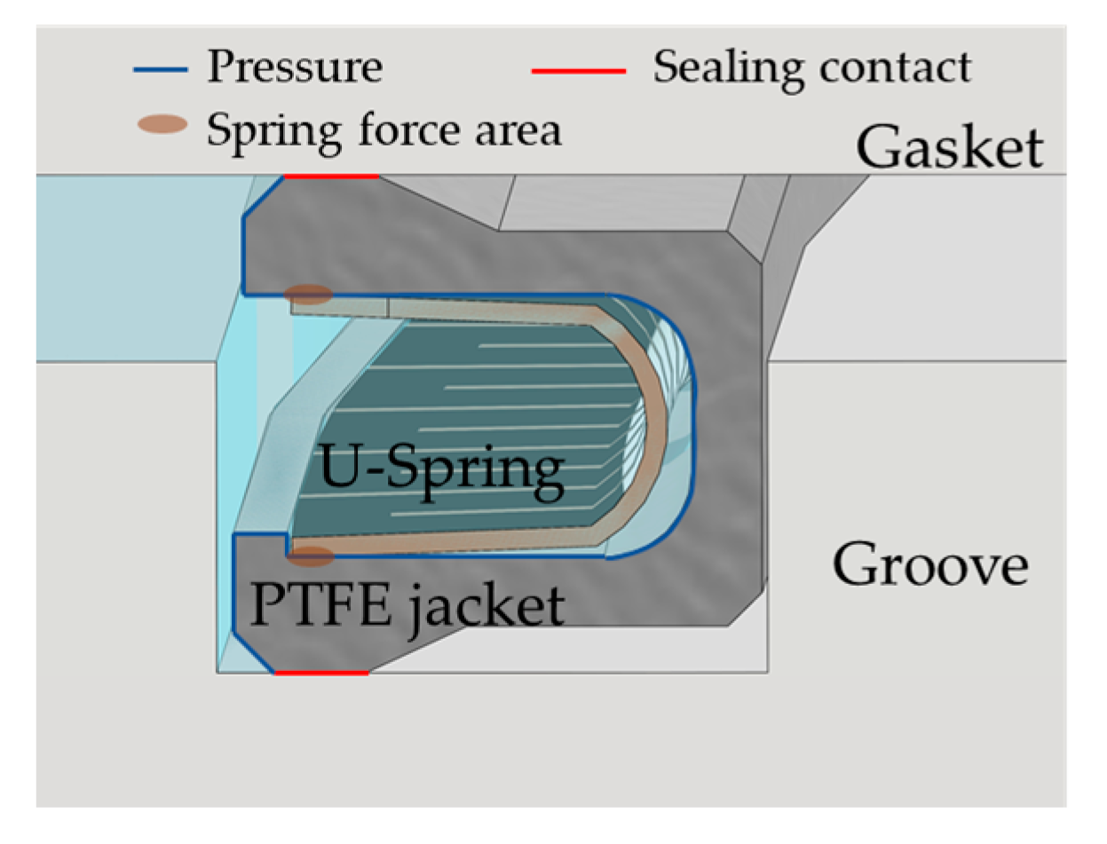
2.1. Structure and Working Principle of Face Rotary Spring-Energized Seals

The spring-energized seal used for evaluation in this study is shown in Figure 1. The spring-energized seal used is primarily composed of a PTFE jacket and a metal U-spring. The sealing principle is as follows: at low or medium pressure, the spring-energized seal is sealed by the spring force generated by the deformation of the seal, and at high pressure, it is largely dependent on the pressure acting on the seal [22]. The model is composed of a groove, gasket, jacket, and U-shaped spring. In order to account for calculation efficiency and accuracy, a two-dimensional axisymmetric model was used for simulation calculation and analysis. The deformation of the groove and gasket is very small relative to the spring-energized seal. Therefore, a two-dimensional axisymmetric rigid body was selected as the type of component to be used. The equivalent thickness of the U-shaped metal spring was 0.132 mm, and a comparison between the simulations and tests of spring compression is shown in Figure 2. It can be seen that there is a linear relationship between the deflection and the force in the range of working compression.
The two-dimensional axisymmetric equivalent model of the spring-energized seal is shown in Figure 3. The mesh-agnostic verification of the metal spring used the spring compression reaction force and the maximum Mises stress at a 20% compression ratio as its main indicators. The mesh-agnostic verification of the jacket took the Mises stress and the contact stress of the sealing surface at a 20% compression ratio as its main indicators. When the mesh size of the jacket was 0.02 mm and the mesh size of the metal spring was 0.03 mm, the calculation accuracy and calculation efficiency requirements could be met at the same time.
The material of the U-shaped metal spring was cold-hardened 316 stainless steel. The stress–strain relationship was determined using tensile testing. The ideal elastic–plastic model was used to fit the stress–strain relationship of the metal spring. Its mechanical properties are shown in Table 1.

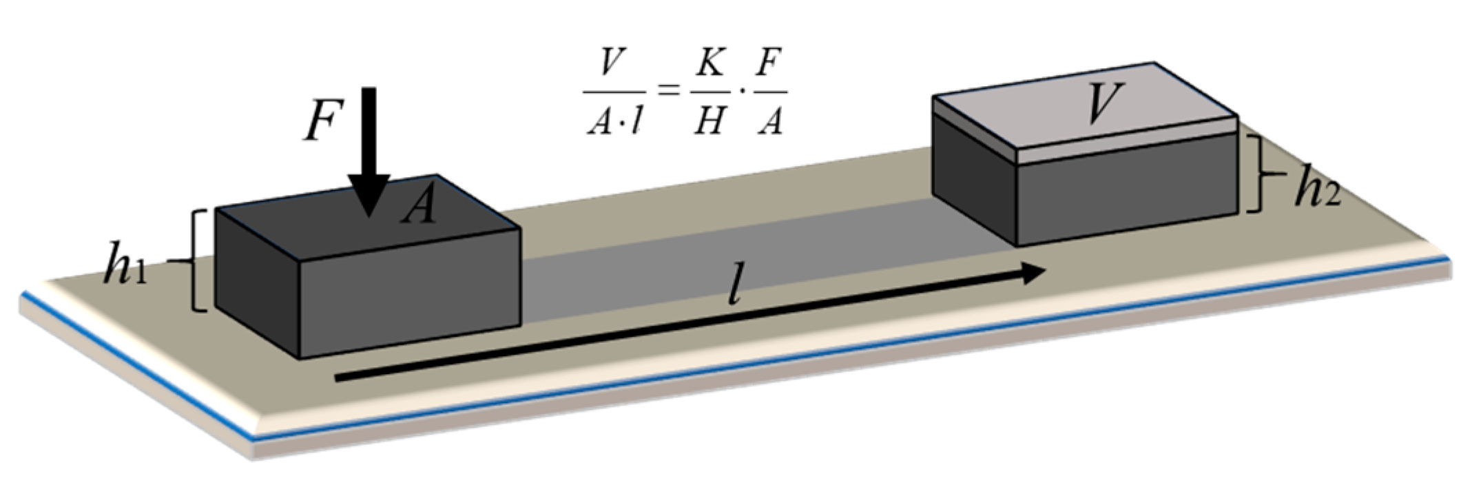
2.2. Modified Archard Wear Model for Spring-Energized Seals

The Archard wear model is widely used in finite element analysis of material wear. The wear principle is shown in Figure 4:
V A × l = K H w × F A ,
where V is the wear volume (mm3), A is the wear contact area (mm2), F is the applied normal force (N), l is the relative slip distance (mm), K is the wear coefficient of the material, and Hw is the hardness of the material (MPa).
In order to facilitate the calculation of wear depth during simulation, the Archard wear model is modified as follows:
h w = m × l × P ,
in which the wear depth hw (mm), the contact pressure P (MPa), and the wear rate m (mm2/N) can be obtained via the follow equations:
h w = V A ,   P = F A ,   m = K H w
The wear coefficient K is a dimensionless empirical number. Due to the use of a single material for friction, the hardness of the material is a fixed value. The introduction of a wear rate m can further unify the equation. In this way, the wear amount, load, relative motion speed, and wear time obtained in the tribological experiments can be fitted to obtain the wear coefficient, eliminating the measurement of the hardness of the material.
Formula (2) was coded into a user subroutine UMESHMOTION of the commercial finite element package ABAQUS 2016 (Vélizy-Villacoublay, France) to evaluate the wear amount; a flowchart of the numerical analysis procedures is shown in Figure 5.

2.3. Preparation of PTFE Composites with Wear-Resistant Fillers

In order to improve the tribological performance of spring-energized seals made of PTFE, we added BaSO4, glass fiber, Si3N4, MoS2, graphite, WS2, and carbon nanotubes to PTFE (25 μm, MACKLIN, Shanghai, China) to prepare PTFE composites with varied fillers [23,24]. The details of this process are listed in Table 2. PTFE samples were obtained after five processes of drying, mixing, pressing, sintering, and machining. The PTFE and fillers were dried separately in a drying oven at 85 °C for 1 h. The dried powder was placed in a planetary mill for mixing treatment, and the mixing time was set to 2 h. Then, the PTFE powder was pressed at a pressure of 50 MPa for 10 min. Finally, the pressed cylindrical PTFE was placed in a sintering furnace for sintering, and the heating rate was controlled by the following heating steps. The first step was to heat at 100 °C for 30 min, the second step was to heat up to 200 °C for 60 min, the third step was to heat up to 365 °C for 120 min, and the fourth step was to naturally cool down to room temperature (26 °C) [25,26,27]. After sintering, the filled PTFE rods were machined to obtain filled PTFE samples for tribological testing. The filled PTFE rods were cylinders with diameters of 30 mm.

3. Results and Discussion

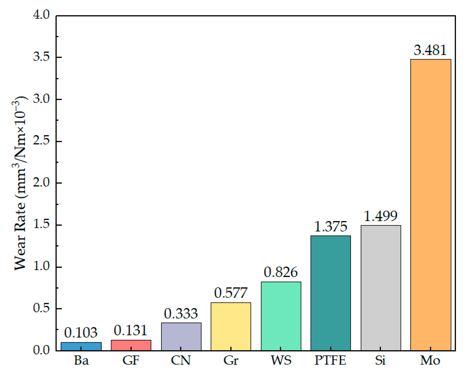
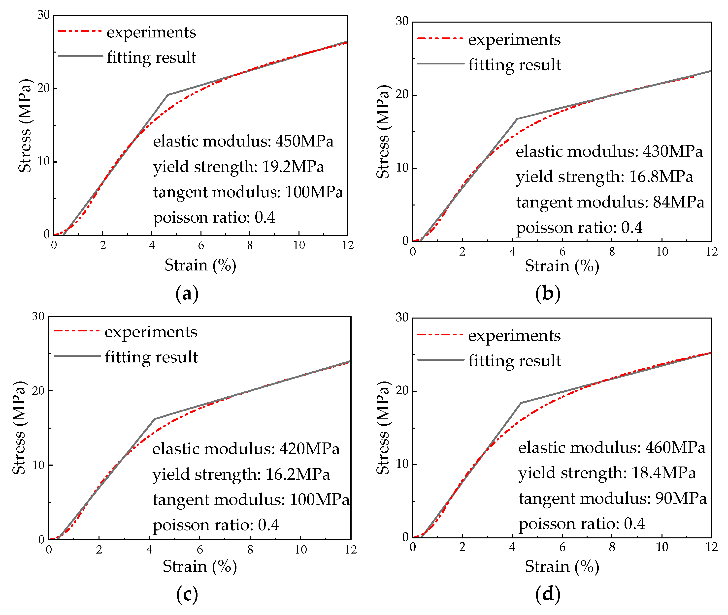
3.1. Performance Testing of PTFE Composites with Wear-Resistant Fillers

The PTFE friction samples are shown in Figure 6, which utilized cylinders with diameters of 30 mm and heights of 15 mm. In order to obtain the tribological parameters required for the performance prediction model for spring-energized seals, the tribological behaviors of the PTFE samples were examined on a tribomachine (MMU-10G, Dacheng Testing Machine Co., Ltd., Shandong, China) using the disk-on-disk friction configuration. The PTFE disks were tested against 304 stainless steel disks with a roughness of Ra = 0.2 μm at room temperature (26 °C). The normal load in the test was 100 N, the speed was 100 rpm, and the wear time was 30 min. The wear rate was estimated from the mass lost by the samples.
The morphology of the PTFE samples was observed with an image measuring instrument (TM-151510CAZ, Beijing Zhongjing Instrument Technology Co., Ltd., Beijing, China), and the influence of the filler on the PTFE was analyzed. The observation results are shown in Figure 7. As seen in Figure 7, the surface of the pure PTFE was flat and smooth. The granular BaSO4, Si3N4, MoS2, and WS2 were effectively incorporated into the PTFE matrix, and the surfaces after processing were relatively flat. The fibrous glass fiber, carbon nanotubes, and flake graphite were combined with PTFE. There was a certain anisotropy in the composite material, and the surface was scaly after processing. The friction coefficients of each filled PTFE under dry friction are depicted in Figure 8. When the filled PTFE achieved stable friction, the measurements in friction coefficient, from low to high, were as follows: GF/PTFE, Mo/PTFE, Gr/PTFE, WS/PTFE, Si/PTFE, CN/PTFE, Ba/PTFE, PTFE. The friction coefficient of pure PTFE was approximately 0.154, while the friction coefficients of Ba/PTFE and CN/PTFE were comparable to that of pure PTFE, measuring at 0.146 (Ba) and 0.141 (CN), respectively. The friction coefficients of Si/PTFE, WS/PTFE, and Gr/PTFE were similar, with values of 0.126 (Si), 0.123 (WS), and 0.121 (Gr). The friction coefficients of Mo/PTFE and GF/PTFE were the lowest, with values of 0.114 (Mo) and 0.111 (GF).
Figure 9 shows the wear rate m of different types of filled PTFE according to the Archard wear model. The wear rates, from low to high, were as follows: Ba/PTFE, GF/PTFE, CN/PTFE, Gr/PTFE, WS/PTFE, PTFE, Si/PTFE, Mo/PTFE. The wear rates of Si/PTFE and Mo/PTFE were even larger than that of pure PTFE, which indicated that the addition of Si3N4 and WS2 mainly reduced the friction coefficient of PTFE but also reduced the wear resistance of PTFE. The wear rates of Ba/PTFE and GF/PTFE were the lowest, with values of 0.103 × 10⁻³ (Ba) and 0.131 × 10⁻³ (GF).
After considering the friction coefficient and wear rate, GF/PTFE, Mo/PTFE, Ba/PTFE, and pure PTFE were selected to analyze the effect of jacket materials on the performance of spring-energized seals. By comparing the strength characteristics and friction characteristics of the spring-energized seals made of these materials, the influence of the friction coefficient and wear rate on the wear of the seal ring was analyzed.
A fatigue testing system (8801, Instron, Norwood, MA, USA) was used to carry out a tensile test on the above four types of filled PTFE (according to GB/T 39714.2-2020 [28]) at a tensile speed of 5 mm/min. The size of the sample was a dumbbell-shaped specimen with a maximum diameter of 20 mm and a length of 100 mm. The bilinear isotropic hardening elastic–plastic material model was used to fit the stress–strain relationship of PTFE. The tensile test curves are shown in Figure 10.

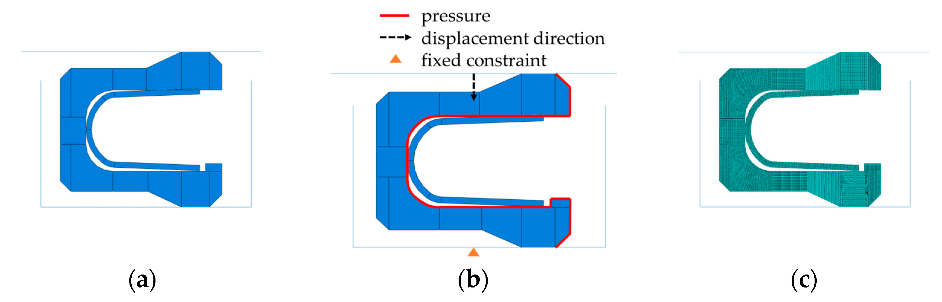
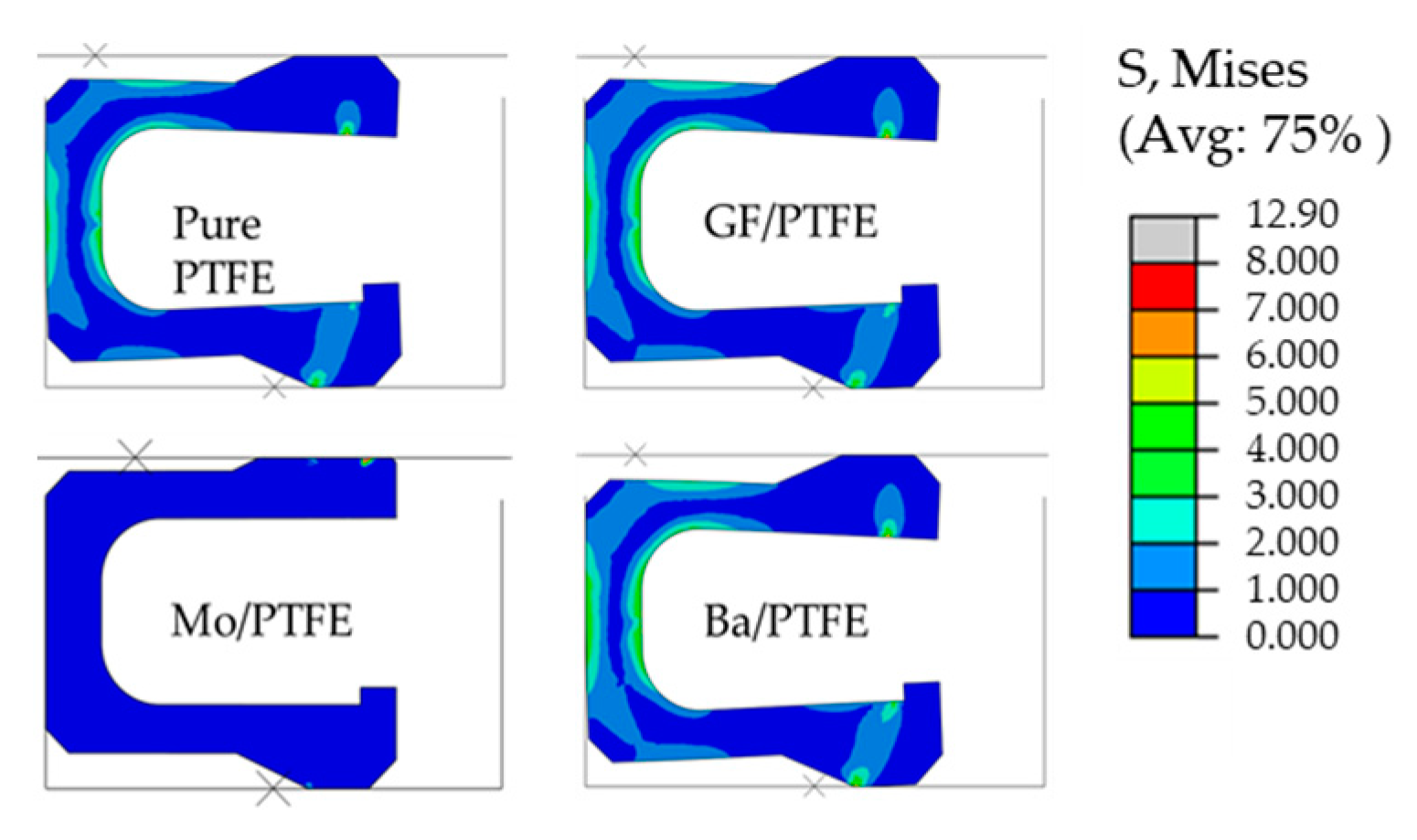
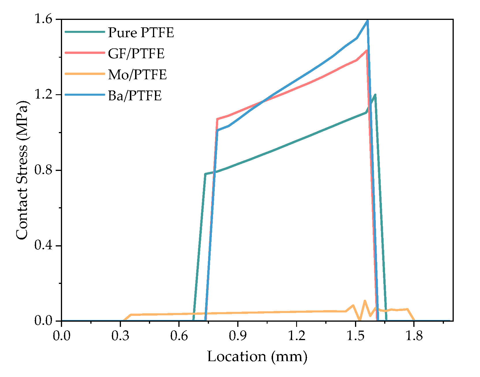
3.2. Simulation Analysis

The material parameters obtained from the test were brought into the performance prediction model, and wear analyses were carried out for the spring-energized seals made of the selected PTFEs. Figure 11 shows the distribution of the Mises stress on the jackets made with different types of PTFE after the PTFE underwent wear. It can be found that after a relative slip of 413,000 mm, due to the wear of the jacket material, the Mises stress on the sealing surface of the four materials was reduced to less than 1 MPa. Among the various materials, the spring-energized seal made of Mo/PTFE was seriously worn, and the Mises stress of this jacket was, on the whole, low. Under wear, the friction coefficient has little effect on the Mises stress distribution of the whole sealing jacket and has no effect on the Mises stress distribution on the sealing surface. However, the wear rate has a great influence on the Mises stress distribution of the whole sealing jacket. The Mises stress of the spring-energized seals made of PTFE corresponding to lower wear rates was larger after wear.
The contact stress distribution on the sealing surface of different PTFEs after wear is shown in Figure 12. With an increase in the wear rate, the contact stress on the sealing surface decreased and the contact width increased. However, the increase in the wear rate did not affect the contact stress distribution, and the maximum contact stress was still on the medium side. In the wear rate range of 1.03 × 10⁻⁷~3.48 × 10⁻⁶ mm3/Nm, the maximum contact stress of the sealing surface decreases from 1.98 MPa to 0.11 MPa, and the contact width of the sealing surface increases from 0.88 mm to 1.49 mm. Therefore, during the operation cycles, the greater the wear rate of the jacket material, the more serious the wear will be, and the width of the contact surface will increase. At the same time, a decrease in the spring compression will reduce the sealing pressure of the sealing ring and the contact stress of the sealing surface.
The evolution of the friction torque of the spring-energized seals with different filled PTFE jackets is presented in Figure 13. Comparing the friction torque changes in Ba/PTFE and GF/PTFE in Figure 13, it can be seen that when the wear rates were similar, the friction coefficient of the material was an important factor affecting the friction torque of the spring-energized seals. Comparing the friction torque changes in Mo/PTFE and GF/PTFE in Figure 13, it can be observed that their friction coefficients were similar, while the wear rates were 26.56 times larger, and the friction torque reduction rates were 95.09% and 24.12%, a 3.94-fold difference. The friction coefficient of GF/PTFE was the lowest, and the wear rate was slightly higher than that of Ba/PTFE. Therefore, the friction torque of the spring-energized seal made of GF/PTFE was lower, and the wear generated during use was lesser. These properties can meet the requirements of both low friction and long service life. Compared with the spring-energized seal made of pure PTFE, the friction torque of the spring-energized seal made of GF/PTFE was reduced by a maximum of 28.97%, and the friction torque reduction rate decreased by 22.25%.

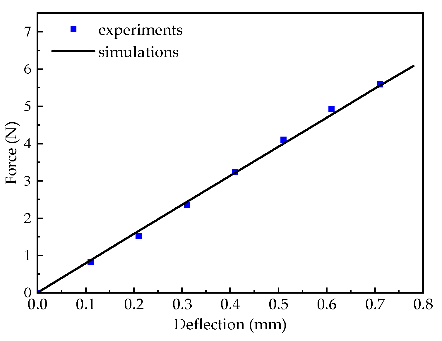
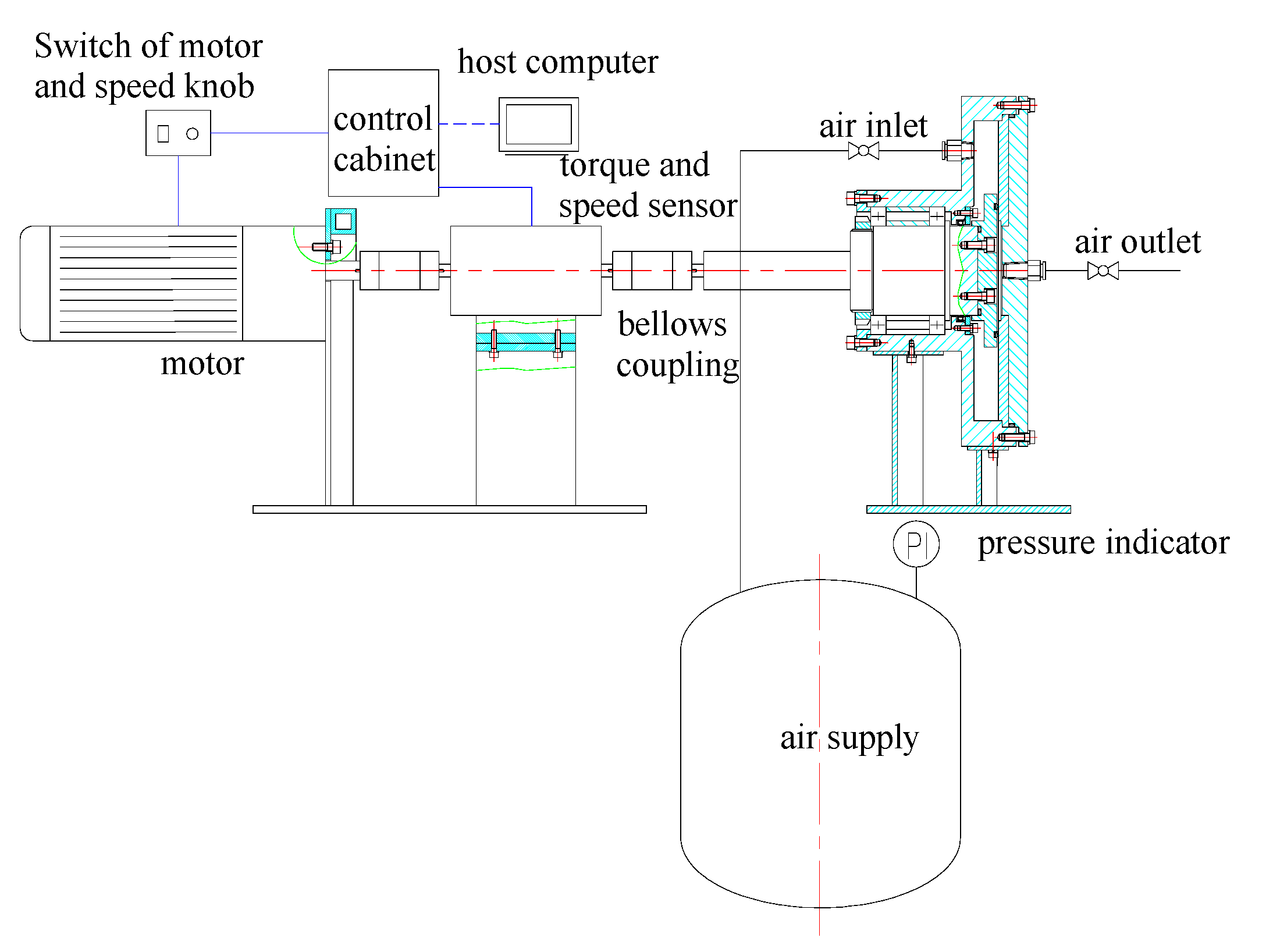
3.3. Experimental Verification

Figure 14 shows the wear test equipment for the spring-energized seals under dry friction conditions [20]. The spring-energized seal was installed in the groove. Screws were used to tighten the groove and the shaft. The groove would rotate with the shaft, and the metal plate was stationary. One end of the shaft was supported by two ball bearings in the tooling to reduce the misalignment and vibration caused by the connection of multiple couplings. The other end was connected to the output end of the torque speed sensor through the bellow coupling to measure the actual output torque and real-time speed of the motor. The input end of the torque speed sensor was connected to the motor through a bellow coupling, and the motor rotated at a set speed. The host computer recorded the actual output torque and real-time speed of the motor through the control cabinet. The gas source provided moderate pressure with a volume of 30 L. A single crystalline silicon pressure transmitter was used to measure the pressure of the sealing chamber.
A spring-energized seal made of GF/PTFE was placed in the dry friction test equipment for testing. The comparison between the experimental results and the simulation results is shown in Figure 15. The calculated frictional torque of the spring-energized seal made of GF/PTFE, based on the Archard wear model, was in good agreement with the experimental value. When the sliding distance was short, the fluctuation in the simulation results was large. After a certain amount of wear, the deviation between the simulation data and the test data was within ±5%.

4. Conclusions

PTFE composites with varied fillers were prepared, and their surface morphology, tribological properties, and mechanical properties were tested. A performance prediction model based on the Archard wear model was used for friction wear simulation analysis of the spring-energized seals. Friction torque tests were conducted on a spring-energized seal made of GF/PTFE using wear test equipment. Through the above work, the following conclusions were obtained:
(1)
The addition of 5 wt.% filler had a negligible influence on the mechanical properties of the PTFEs but significantly impacted their tribological performance. The friction coefficient of the jacket material had little effect on the stress distribution of the whole jacket and primarily affected the friction torque of the spring-energized seal. With an increase in the wear rate, the contact stress on the sealing surface decreased, the contact width increased, and the friction torque decreased faster. The wear rates of the jacket material were 26.56 times larger, and the friction torque reduction rates were 95.09% and 24.12%, a 3.94-fold difference.
(2)
The wear simulation model based on the Archard wear model can accurately simulate the sealing performance of spring-energized seals with different filled PTFE jackets after wear. After a certain amount of wear, the deviation between the simulation data and the test data was within ±5%.
(3)
When the performance prediction model was used to improve the jacket material of the spring-energized seal, it was found that, compared to the spring-energized seal made of pure PTFE, the friction torque of the spring-energized seal made of GF/PTFE was reduced by a maximum of 28.97%, and the friction torque reduction rate decreased by 22.25%.

Author Contributions

Conceptualization, S.L. and X.Z.; methodology, S.L. and X.Z.; software, X.Z. and D.L.; validation, S.L., X.Z., D.L. and L.H.; formal analysis, X.Z.; investigation, X.Z.; resources, S.L.; data curation, X.Z., D.L. and L.H.; writing—original draft preparation, X.Z.; writing—review and editing, S.L., X.Z. and D.L.; visualization, X.Z.; supervision, S.L.; project administration, S.L.; funding acquisition, S.L. All authors have read and agreed to the published version of the manuscript.

Funding

This research received no external funding.

Data Availability Statement

Some data presented in this article are not readily available for confidentiality reasons. Requests to access the datasets should be directed to S.L.

Acknowledgments

I would like to express my gratitude to Shuangxi Li, my mentor, for his invaluable help and support throughout the process of writing this paper. Additionally, I am grateful to Dengyu Liu for his guidance in software usage, paper writing techniques, and test procedures.

Conflicts of Interest

The authors declare no conflicts of interest.

References

  1. Amenta, F.; Bolelli, G.; De Lorenzis, S.; Bertarini, A.; Lusvarghi, L. Tribological Behavior of Reinforced PTFE Composites and Un-Reinforced Polyketone-Based Materials against Coated Steel. Lubricants 2021, 10, 5. [Google Scholar] [CrossRef]
  2. Ma, K.; Guan, K.; Cai, R. Compression recovery performance of spring energized C-rings. Proc. Inst. Mech. Eng. Part E J. Process Mech. Eng. 2014, 230, 18–25. [Google Scholar] [CrossRef]
  3. Peng, S.; Guo, Y.; Xie, G.; Luo, J. Tribological behavior of polytetrafluoroethylene coating reinforced with black phosphorus nanoparticles. Appl. Surf. Sci. 2018, 441, 670–677. [Google Scholar] [CrossRef]
  4. Zhao, Y.; Qi, X.; Ma, J.; Dong, Y.; Yang, Y. Effects of polyimide/silica and polyimide/pores fillers on the morphology, thermal, mechanical, and tribological properties of polytetrafluoroethylene composites. Polym. Compos. 2019, 40, 3438–3452. [Google Scholar] [CrossRef]
  5. Vasilev, A.P.; Struchkova, T.S.; Alekseev, A.G. Development of Antifriction Materials Based on Polytetrafluoroethylene with Carbon Fibers and Tungsten Disulfide. Mater. Sci. Forum 2020, 992, 745–750. [Google Scholar] [CrossRef]
  6. Fan, M.; He, W.; Li, Q.; Zhou, J.; Shen, J.; Chen, W.; Yu, Y. PTFE Crystal Growth in Composites: A Phase-Field Model Simulation Study. Materials 2022, 15, 6286. [Google Scholar] [CrossRef]
  7. Bhargava, S.; Blanchet, T.A. Unusually Effective Nanofiller a Contradiction of Microfiller-Specific Mechanisms of PTFE Composite Wear Resistance? J. Tribol. 2016, 138, 042001. [Google Scholar] [CrossRef]
  8. Bhargava, S.; Makowiec, M.E.; Blanchet, T.A. Wear reduction mechanisms within highly wear-resistant graphene- and other carbon-filled PTFE nanocomposites. Wear 2020, 444–445, 203163. [Google Scholar] [CrossRef]
  9. Fan, X.; Li, G.; Guo, Y.; Zhang, L.; Xu, Y.; Zhao, F.; Zhang, G. Role of reinforcement types and silica nanoparticles on tribofilm growth at PTFE-Steel interface. Tribol. Int. 2020, 143, 106035. [Google Scholar] [CrossRef]
  10. Qiu, X.; Fu, C.; Gu, A.; Gao, Y.; Wang, X.; Yu, Z. Preparation of high-performance PEEK anti-wear blends with melt-processable PTFE. High Perform. Polym. 2019, 32, 645–654. [Google Scholar] [CrossRef]
  11. Fang, K. Frictional Performance of Polyphenyl Ester Modified Polytetrafluoroethylene. Mater. Sci. Forum 2023, 1080, 33–39. [Google Scholar] [CrossRef]
  12. Ma, G.; Ding, G.; Liu, X.; Wang, H.; Zhai, H.; Zhu, H. Change in Surface Microstructure and Properties of PTFE after Solar Radiation and its Mechanism. J. Wuhan Univ. Technol.-Mater. Sci. Ed. 2019, 34, 223–229. [Google Scholar] [CrossRef]
  13. Chen, S.; Guo, F.; Wang, W.; Wang, Y. An improved mixed lubrication model for revealing the mechanism of high speed and frictional heat on sealing performance. Tribol. Int. 2024, 191, 109147. [Google Scholar] [CrossRef]
  14. Huang, T.-C.; Lin, C.-Y.; Liao, K.-C. Experimental and numerical investigations of the wear behavior and sealing performance of PTFE rotary lip seals based on the elasto-hydrodynamic analysis with considerations of the asperity contact. Tribol. Int. 2023, 187, 108747. [Google Scholar] [CrossRef]
  15. Huang, T.C.; Lin, C.Y.; Liao, K.C. Sealing performance assessments of PTFE rotary lip seals based on the elasto-hydrodynamic analysis with the modified archard wear model. Tribol. Int. 2022, 176, 107917. [Google Scholar] [CrossRef]
  16. Huang, T.C.; Tsai, J.W.; Liao, K.C. Wear and leakage assessments of canted coil Spring–Energized polytetrafluoroethylene seals under Ultra-High cycle operations. Eng. Fail. Anal. 2022, 135, 106–110. [Google Scholar] [CrossRef]
  17. Amenta, F.; Bolelli, G.; Pedrazzi, S.; Allesina, G.; Santeramo, F.; Bertarini, A.; Sassatelli, P.; Lusvarghi, L. Sliding wear behaviour of fibre-reinforced PTFE composites against coated and uncoated steel. Wear 2021, 486–487, 204097. [Google Scholar] [CrossRef]
  18. Song, F.; Wang, Q.; Wang, T. Effects of glass fiber and molybdenum disulfide on tribological behaviors and PV limit of chopped carbon fiber reinforced Polytetrafluoroethylene composites. Tribol. Int. 2016, 104, 392–401. [Google Scholar] [CrossRef]
  19. Makowiec, M.E.; Blanchet, T.A. Improved wear resistance of nanotube- and other carbon-filled PTFE composites. Wear 2017, 374–375, 77–85. [Google Scholar] [CrossRef]
  20. Liu, D.; Zhao, J.; Li, S.; Zhao, X.; Huang, L. Experimental Study on Tribological and Leakage Characteristics of a Rotating Spring-Energized Seal under High and Low Temperature. Machines 2023, 11, 221. [Google Scholar] [CrossRef]
  21. Wang, A.; Lin, B.; Zou, H.; Wei, C.; Meng, Y.; Sui, T.; Yan, S. Effect of micrometer sized ceramic particles on the tribological properties of Polytetrafluoroethylene based composites. Surf. Topogr. Metrol. Prop. 2020, 8, 035005. [Google Scholar] [CrossRef]
  22. Raparelli, T.; Mazza, L.; Trivella, A. Experimental analysis and preliminary model of non-conventional lip seals. Tribol. Int. 2023, 181, 108311. [Google Scholar] [CrossRef]
  23. Dhanumalayan, E.; Joshi, G.M. Performance properties and applications of polytetrafluoroethylene (PTFE)—A review. Adv. Compos. Hybrid Mater. 2018, 1, 247–268. [Google Scholar] [CrossRef]
  24. Vasilev, A.P.; Lazareva, N.N.; Struchkova, T.S.; Okhlopkova, A.A.; Danilova, S.N. Mechanical and Tribological Properties of Polytetrafluoroethylene Modified with Combined Fillers: Carbon Fibers, Zirconium Dioxide, Silicon Dioxide and Boron Nitride. Polymers 2023, 15, 313. [Google Scholar] [CrossRef] [PubMed]
  25. Khanna, Y.P. The melting temperature of polytetrafluoroethylene. J. Mater. Sci. Lett. 1988, 7, 817–818. [Google Scholar] [CrossRef]
  26. Vasilev, A.P.; Struchkova, T.S.; Okhlopkova, A.A. Effects of Complex Fillers on the Mechanical and Tribological Properties of Polytetrafluoroethylene Composites. Mater. Sci. Forum 2020, 992, 739–744. [Google Scholar] [CrossRef]
  27. Bhargava, S.; Koratkar, N.; Blanchet, T.A. Effect of Platelet Thickness on Wear of Graphene–Polytetrafluoroethylene (PTFE) Composites. Tribol. Lett. 2015, 59, 17. [Google Scholar] [CrossRef]
  28. GB/T 39714.2-2020; Plastics—Polytetrafluoroethylene (PTFE) Semi-Finished Products—Part 2: Preparation of Test Specimens and Determination of Properties. Standardization Administration of China (SAC): Beijing, China, 2020.
Figure 1. Structure of the spring-energized seal.
Lubricants 12 00288 g001
Figure 2. Compressive force–deflection dependence based on the experiments and simulations.
Lubricants 12 00288 g002
Figure 3. (a) Geometric model; (b) constraint condition; (c) mesh.
Lubricants 12 00288 g003
Figure 4. Archard wear theory.
Lubricants 12 00288 g004
Figure 5. Flowchart of the numerical analysis procedures.
Lubricants 12 00288 g005
Figure 6. PTFE friction samples filled with varied fillers: (a) PTFE; (b) Ba/PTFE; (c) GF/PTFE; (d) Si/PTFE; (e) Mo/PTFE; (f) Gr/PTFE; (g) WS/PTFE; (h) CN/PTFE.
Lubricants 12 00288 g006
Figure 7. Surface morphology of PTFE friction sample filled with varied fillers (×1000): (a) PTFE; (b) Ba/PTFE; (c) GF/PTFE; (d) Si/PTFE; (e) Mo/PTFE; (f) Gr/PTFE; (g) WS/PTFE; (h) CN/PTFE.
Lubricants 12 00288 g007
Figure 8. Coefficient of friction of the PTFE composites with varied fillers.
Lubricants 12 00288 g008
Figure 9. The wear rates of the PTFE composites with varied fillers.
Lubricants 12 00288 g009
Figure 10. Tensile test curves of PTFE materials: (a) GF/PTFE; (b) Mo/PTFE; (c) Ba/PTFE; (d) pure PTFE.
Lubricants 12 00288 g010
Figure 11. Mises stress distribution after wear with different PTFE jackets.
Lubricants 12 00288 g011
Figure 12. Contact stress distribution on the sealing surface after wear using different PTFE jackets.
Lubricants 12 00288 g012
Figure 13. Relationships between the friction torque of the spring-energized seals with different PTFE jackets and sliding distance.
Lubricants 12 00288 g013
Figure 14. Equipment for wear test under dry friction conditions.
Lubricants 12 00288 g014
Figure 15. Comparison of test and calculated friction torque of the spring-energized seal made of GF/PTFE.
Lubricants 12 00288 g015
Table 1. Mechanical properties of cold-hardened 316 stainless steel.
Elastic Modulus/MPaYield Strength/MPaPoisson RatioTangent Modulus/MPaTensile Strength/MPa
193,50015000.35301567
Table 2. Experimental materials.
SampleFillerSize of FillerContent of Fillers
PTFEnone--
Ba/PTFEBaSO445 μm5 wt.%
GF/PTFEglass fiberdiameter of 13 μm, length of 30 μm5 wt.%
Si/PTFESi3N41–3 μm5 wt.%
Mo/PTFEMoS230–50 μm5 wt.%
Gr/PTFEgraphite40–60 μm5 wt.%
WS/PTFEWS20.85–1.15 μm5 wt.%
CN/PTFEcarbon nanotubesdiameter of 9.5 nm, length of 1.5 μm5 wt.%
Disclaimer/Publisher’s Note: The statements, opinions and data contained in all publications are solely those of the individual author(s) and contributor(s) and not of MDPI and/or the editor(s). MDPI and/or the editor(s) disclaim responsibility for any injury to people or property resulting from any ideas, methods, instructions or products referred to in the content.

