Friction and Wear in Hot Stamping: The Role of Tool and Workpiece Temperature and Tool Steel Composition

Abstract
1. Introduction
2. Experimental Procedure
2.1. Materials
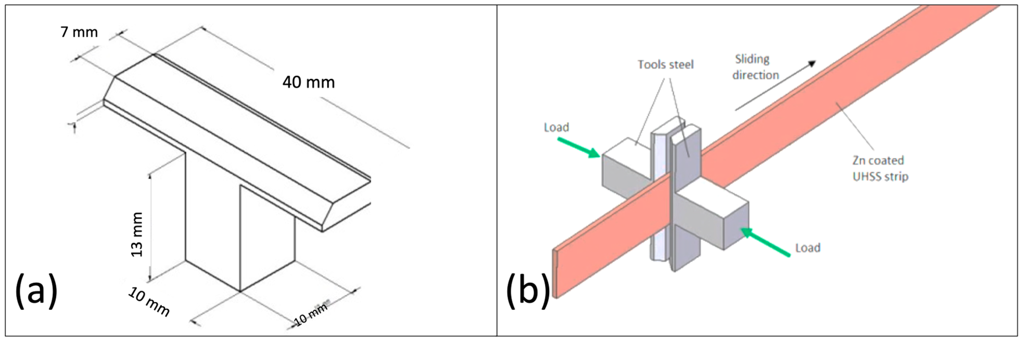
2.2. Test Procedure
2.3. Nano-Scratch Tests
2.4. Sample Preparation
3. Results and Discussion
3.1. Effect of Workpiece Temperature on the Tribological Response
3.2. Effect of Tool Steel Chemistry and Temperature on the Tribological Response
4. Conclusions
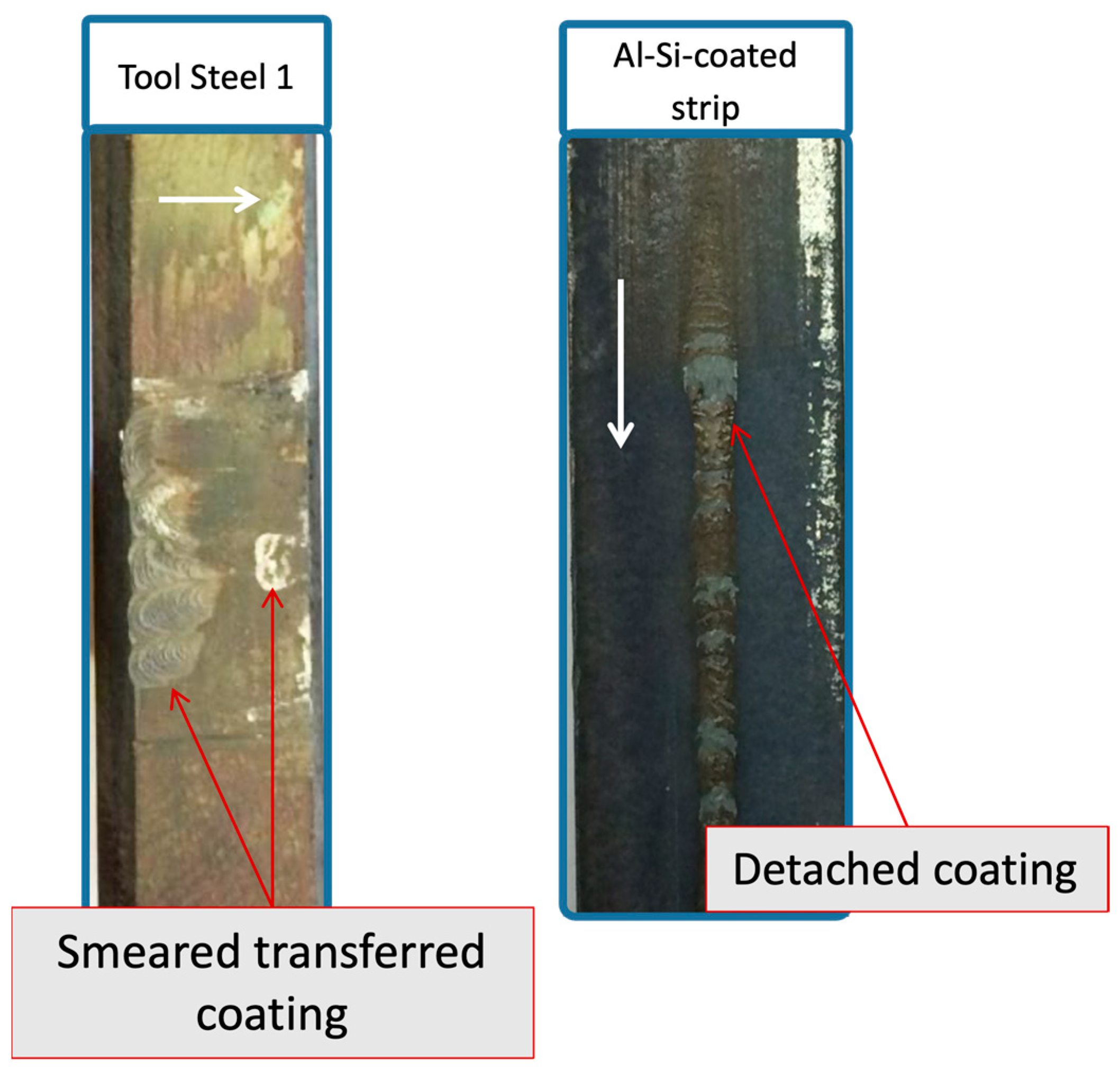
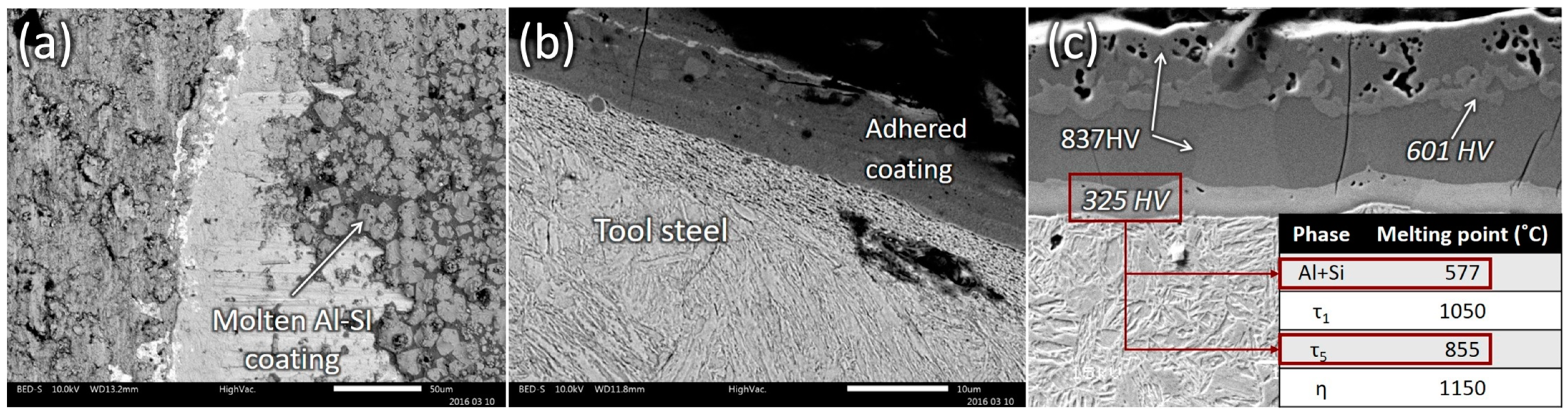
- The high temperature of the workpiece material causes the softening and partial melting of some phases in the Al-Si coating. The high adhesive forces that exist during sliding against tool steel result in the tearing of large fragments of the Al-Si coating and the severe damage of both workpiece material and tool steel.
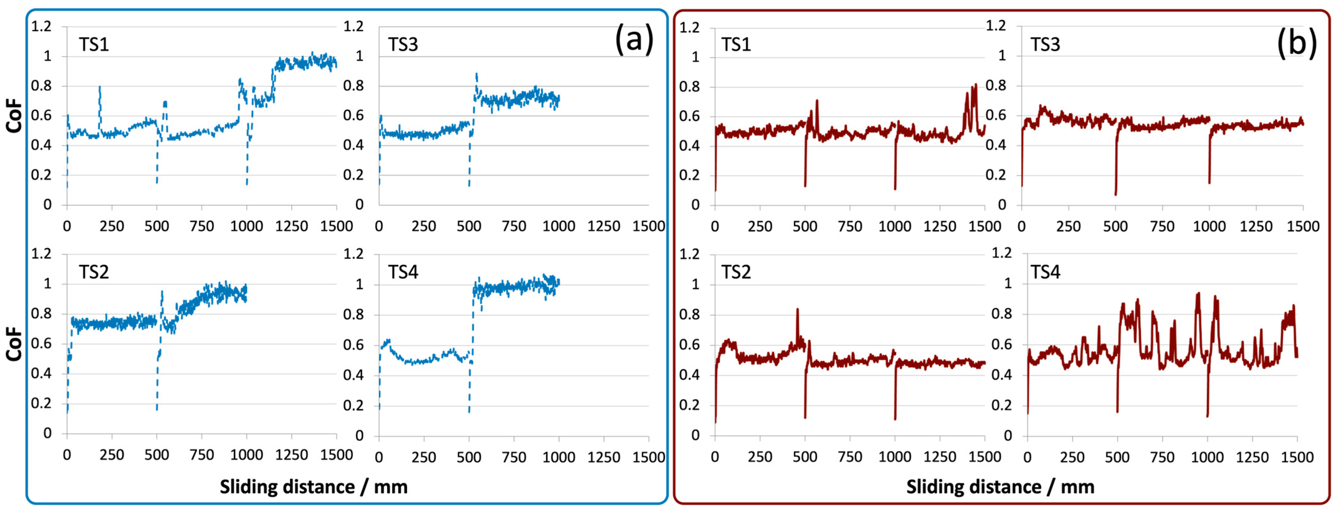
- The tribological behaviour of uncoated tool steels sliding against Al-Si-coated UHSS is affected by the temperature of the tool dies:
- ○
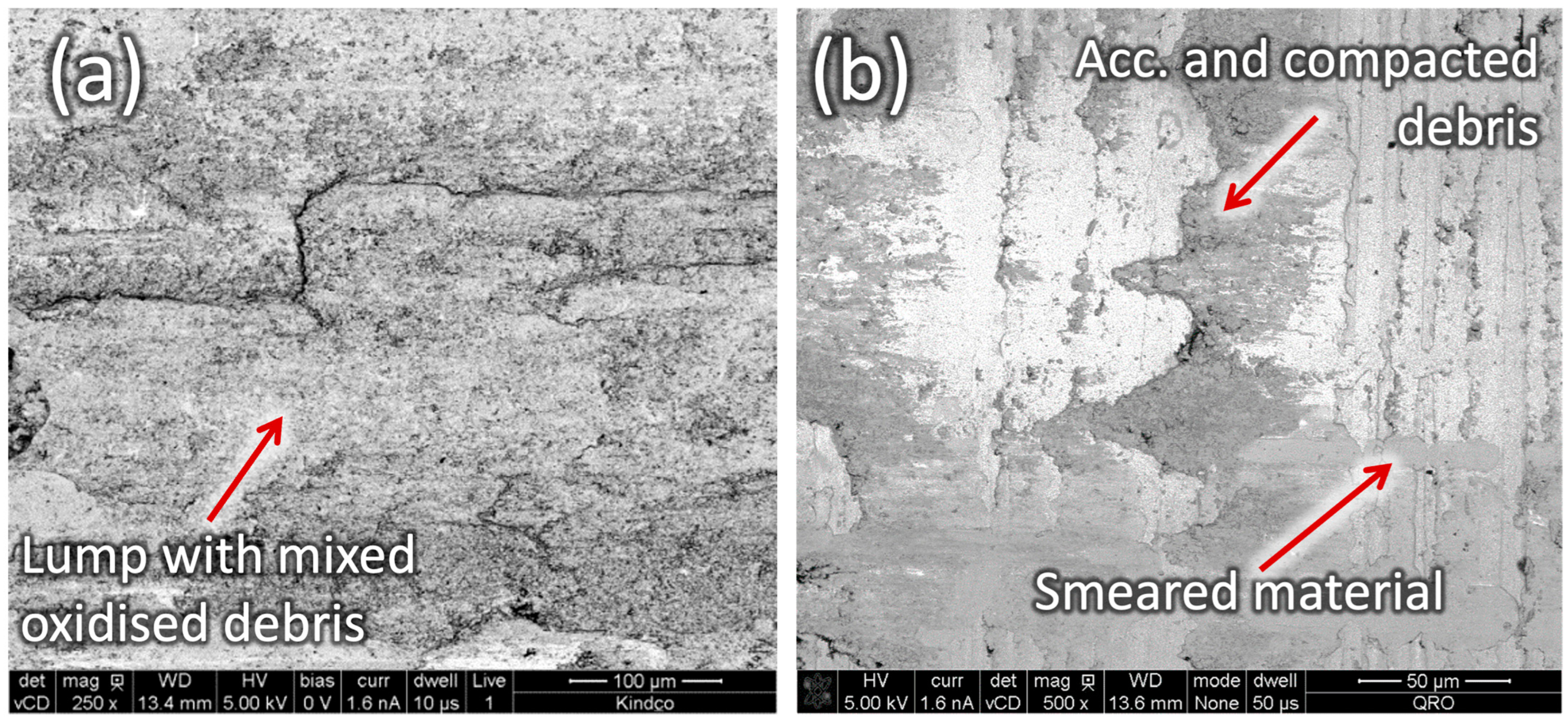
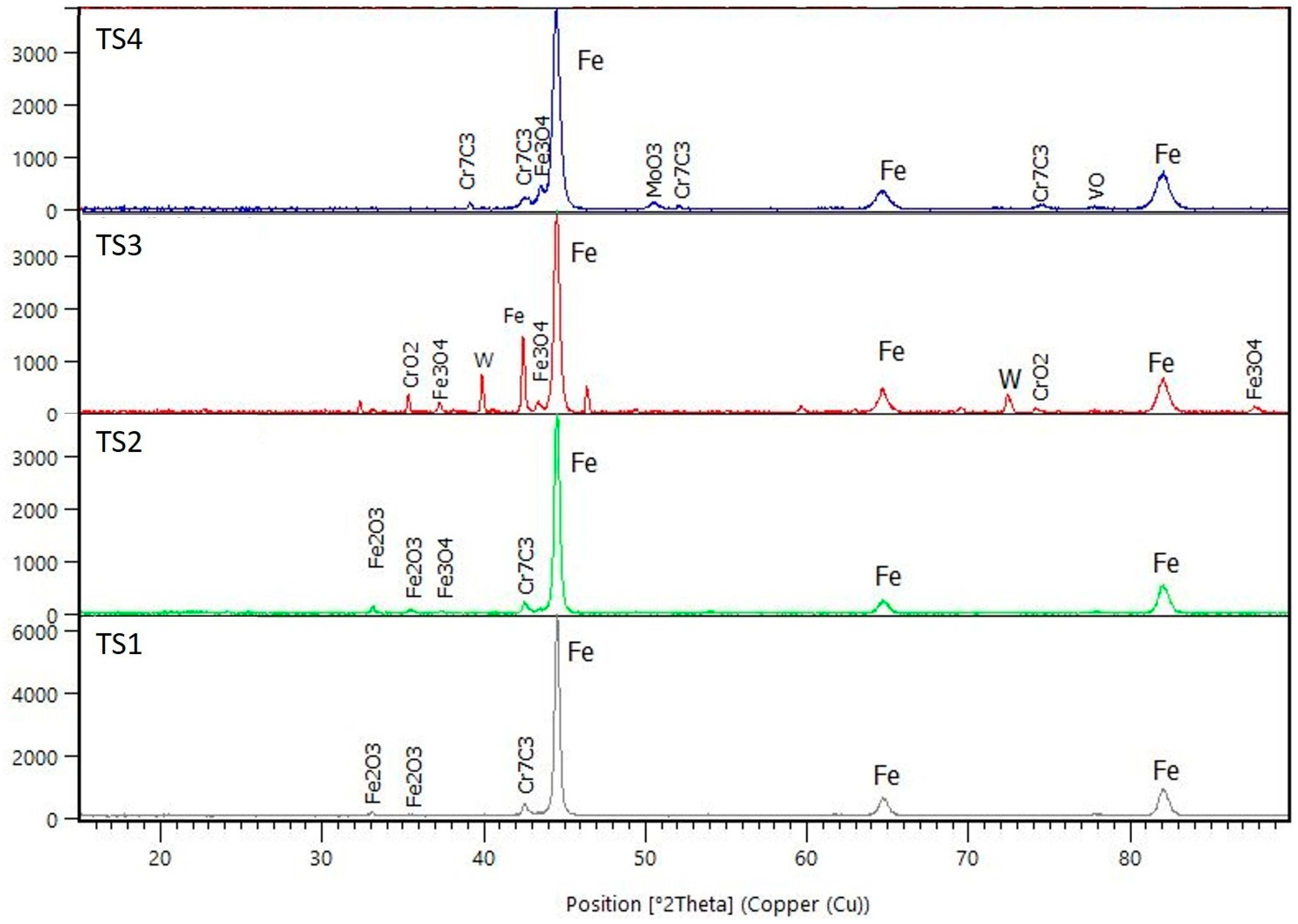
- A more stable coefficient of friction is obtained when heated tool steels are used, and the stable coefficient of friction is directly related to the formation of transfer layers of oxidised wear debris from the coating and the tool steel.
- ○
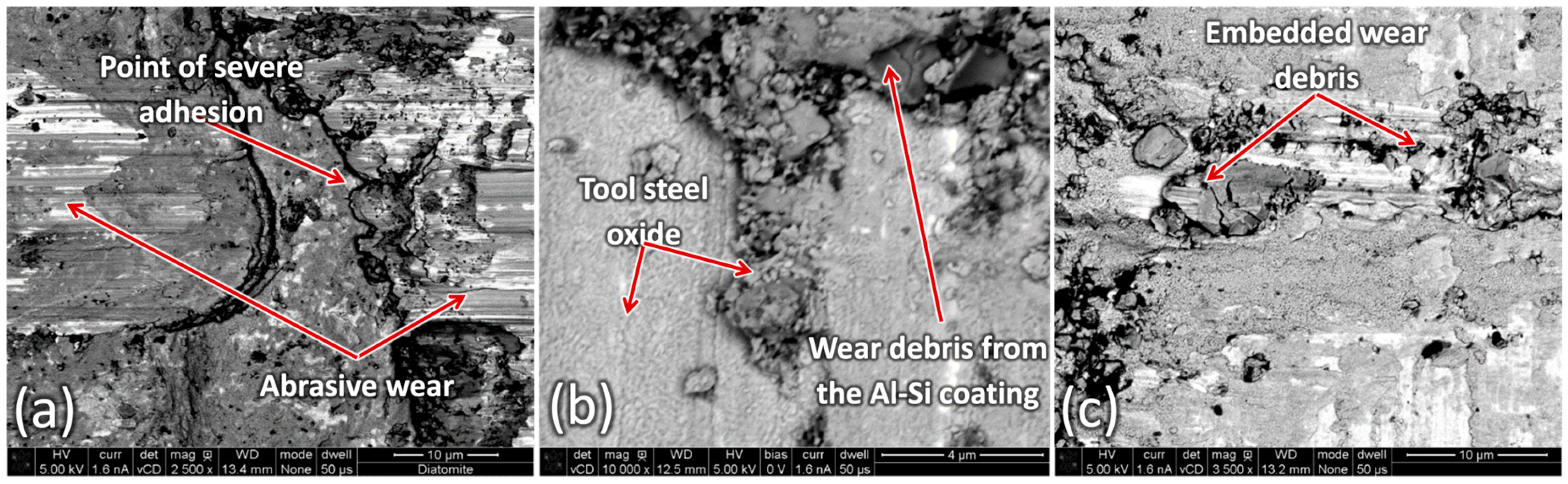
- Adhesive wear occurs both with unheated and heated tool steel. However, the adhesion is more pronounced in the case of unheated tool steel and promotes frictional instabilities.
- ○
- Abrasive wear, micro-ploughing, and the embedding of Al-Si coating fragments occur predominantly when unheated tool steels are used and they affect the frictional stability.
- ○
- The development of transferred material with mixed oxidised wear debris is facilitated at high temperature and it has a friction-stabilising effect.
- High temperature oxidation can result in unstable friction if the formed oxides do not develop stable layers with good adherence to the substrate.
Funding
Data Availability Statement
Acknowledgments
Conflicts of Interest
References
- Karbasian, H.; Tekkaya, A.E. A review on hot stamping. J. Mater. Process. Technol. 2010, 210, 2103–2118. [Google Scholar] [CrossRef]
- Mori, K.; Bariani, P.F.; Behrens, B.-A.; Brosius, A.; Bruschi, S.; Maeno, T.; Merklein, M.; Yanagimoto, J. Hot stamping of ultra-high strength steel parts. CIRP Ann. 2017, 66, 755–777. [Google Scholar] [CrossRef]
- Merklein, M.; Wieland, M.; Lechner, M.; Bruschi, S.; Ghiotti, A. Hot stamping of boron steel sheets with tailored properties: A review. J. Mater. Process. Technol. 2016, 228, 11–24. [Google Scholar] [CrossRef]
- Boher, C.; Le Roux, S.; Penazzi, L.; Dessain, C. Experimental investigation of the tribological behavior and wear mechanisms of tool steel grades in hot stamping of a high-strength boron steel. Wear 2012, 294–295, 286–295. [Google Scholar] [CrossRef]
- Kondratiuk, J.; Kuhn, P. Tribological investigation on friction and wear behaviour of coatings for hot sheet metal forming. Wear 2011, 270, 839–849. [Google Scholar] [CrossRef]
- Ghiotti, A.; Bruschi, S.; Sgarabotto, F.; Bariani, P.F. Tribological performances of Zn-based coating in direct hot stamping. Tribol. Int. 2014, 78, 142–151. [Google Scholar] [CrossRef]
- Ghiotti, A.; Bruschi, S.; Medea, F.; Hamasaiid, A. Tribological behavior of high thermal conduc-tivity steels for hot stamping tools. Tribol. Int. 2016, 97, 412–422. [Google Scholar] [CrossRef]
- Pelcastre, L.; Hardell, J.; Herrera, N.; Prakash, B. Investigations into the damage mechanisms of form fixture hardening tools. Eng. Fail. Anal. 2012, 25, 219–226. [Google Scholar] [CrossRef]
- Yuan, S.; Karamchedu, S.; Fan, Y.; Liu, L.; Nyborg, L.; Cao, Y. A case study for a worn tool steel in the hot stamping process. J. Mater. Res. Technol. 2023, 22, 1065–1075. [Google Scholar] [CrossRef]
- Macêdo, G.; Pelcastre, L.; Hardell, J. High temperature friction and wear of post-machined additively manufactured tool steel during sliding against AlSi-coated boron steel. Wear 2023, 523, 204753. [Google Scholar] [CrossRef]
- Mu, Y.; Simonetto, E.; Scagnolari, M.; Ghiotti, A. Wear in Hot Stamping by Partition Heating. J. Manuf. Mater. Process. 2020, 4, 18. [Google Scholar] [CrossRef]
- Schirdewahn, S.; Spranger, F.; Hilgenberg, K.; Merklein, M. Localized Laser Dispersing of Titanium-Based Particles for Improving the Tribological Performance of Hot Stamping Tools. J. Manuf. Mater. Process. 2020, 4, 68. [Google Scholar] [CrossRef]
- Mozgovoy, S.; Alik, L.; Hardell, J.; Prakash, B. Material transfer during high temperature sliding of Al-Si coated 22MnB5 steel against PVD coatings with and without aluminium. Wear 2019, 426–427, 401–411. [Google Scholar] [CrossRef]
- Deng, L.; Pelcastre, L.; Hardell, J.; Prakash, B.; Oldenburg, M. Experimental Evaluation of Galling under Press Hardening Conditions. Tribol. Lett. 2018, 66, 93. [Google Scholar] [CrossRef]
- Venema, J.; Matthews, D.T.A.; Hazrati, J.; Wörmann, J.; van den Boogaard, A.H. Friction and wear mechanisms during hot stamping of AlSi coated press hardening steel. J. Mater. Process. Technol. 2017, 380–381, 137–145. [Google Scholar] [CrossRef]
- Grigorieva, R.; Drillet, P.; Mataigne, J.-M.; Redjaïmia, A. Phase transformations in the Al-Si coating during the austenitization step. Solid. State Phenom. 2011, 172–174, 784–790. [Google Scholar] [CrossRef]
- Suehiro, M.; Kusumi, K.; Miyakoshi, T.; Maki, J.; Ohgami, M. Properties of aluminum-coated steels for hot-forming. Nippon. Steel Tech. Rep. 2003, 88, 16–21. [Google Scholar]
- Veit, R.; Hofmann, H.; Kolleck, R.; Sikora, S. Investigation of the Phase Formation of AlSi-Coatings for Hot Stamping of Boron Alloyed Steel. AIP Conf. Proc. 2011, 1315, 769–774. [Google Scholar]
- Pelcastre, L.; Hardell, J.; Prakash, B. Investigations into the occurrence of galling during hot forming of Al–Si-coated high-strength steel. Proc. Inst. Mech. Eng. Part. J. 2011, 225, 487–498. [Google Scholar] [CrossRef]
- Pauschitz, A.; Roy, M.; Franek, F. Mechanisms of sliding wear of metals and alloys at ele-vated temperatures. Tribol. Int. 2008, 41, 584–602. [Google Scholar] [CrossRef]
- Pelcastre, L.; Hardell, J.; Prakash, B. Galling mechanisms during interaction of tool steel and Al–Si coated ultra-high strength steel at elevated temperature. Tribol. Int. 2013, 67, 263–271. [Google Scholar] [CrossRef]
- Hernandez, S.; Hardell, J.; Prakash, B. High-Temperature Friction and Wear of Boron Steel and Tool Steel in Open and Closed Tribosystems. Tribol. Trans. 2017, 61, 448–458. [Google Scholar] [CrossRef]
- Vergne, C.; Boher, C.; Gras, R.; Levaillant, C. Influence of oxides on friction in hot rolling: Experimental investigations and tribological modelling. Wear 2006, 260, 957–975. [Google Scholar] [CrossRef]
- Aouadi, S.M.; Gao, H.; Martini, A.; Scharf, T.W.; Muratore, C. Lubricious oxide coatings for extreme temperature applications: A review. Surf. Coat. Technol. 2014, 257, 266–277. [Google Scholar] [CrossRef]
- Fateh, N.; Fontalvo, G.A.; Gassner, G.; Mitterer, C. The Beneficial Effect of High-Temperature Oxidation on the Tribological Behaviour of V and VN Coatings. Tribol. Lett. 2007, 28, 1–7. [Google Scholar] [CrossRef]
- Gulbiński, W.; Suszko, T. Thin films of Mo2N/Ag nanocomposite—The structure, mechani-cal and tribological properties. Surf. Coat. Technol. 2006, 201, 1469–1476. [Google Scholar] [CrossRef]
- Suszko, T.; Gulbiński, W.; Jagielski, J. The role of surface oxidation in friction processes on molybdenum nitride thin films. Surf. Coat. Technol. 2005, 194, 319–324. [Google Scholar] [CrossRef]
- Gassner, G.; Mayrhofer, P.H.; Kutschej, K.; Mitterer, C.; Kathrein, M. Magnéli phase formation of PVD Mo–N and W–N coatings. Surf. Coat. Technol. 2006, 201, 3335–3341. [Google Scholar] [CrossRef]


| Tool Steel | C | Si | Mn | Cr | Mo | V | Co | W | Hardness (HV0.1) |
|---|---|---|---|---|---|---|---|---|---|
| TS1 | 0.38 | 0.30 | 0.75 | 2.60 | 2.25 | 0.90 | - | - | 567 |
| TS2 | 0.45 | 0.30 | 0.40 | 4.50 | 3.0 | 2.0 | 4.50 | - | 543 |
| TS3 | 0.90 | - | - | 4.10 | 5.0 | 1.80 | - | 6.20 | 654 |
| TS4 | 0.82 | 0.70 | 0.40 | 8.0 | 1.60 | 0.60 | - | - | 798 |
| Parameter | Value |
|---|---|
| Load/contact pressure | 500 N/4.8 MPa |
| Sliding speed | 100 mm/s |
| Tool steel temperature | RT* and 500 °C |
| Strip temperature | 700 °C and 900 °C |
| Material | Hardness before Test | Hardness after Test |
|---|---|---|
| TS1 | 567 ± 13.7 | 568 ± 7.7 |
| TS2 | 543 ± 10.2 | 534 ± 23.8 |
| TS3 | 654 ± 22.3 | 602 ± 13.6 |
| TS4 | 798 ± 8.9 | 748 ± 22.6 |
Disclaimer/Publisher’s Note: The statements, opinions and data contained in all publications are solely those of the individual author(s) and contributor(s) and not of MDPI and/or the editor(s). MDPI and/or the editor(s) disclaim responsibility for any injury to people or property resulting from any ideas, methods, instructions or products referred to in the content. |
© 2024 by the author. Licensee MDPI, Basel, Switzerland. This article is an open access article distributed under the terms and conditions of the Creative Commons Attribution (CC BY) license (https://creativecommons.org/licenses/by/4.0/).
Share and Cite
Pelcastre, L. Friction and Wear in Hot Stamping: The Role of Tool and Workpiece Temperature and Tool Steel Composition. Lubricants 2024, 12, 297. https://doi.org/10.3390/lubricants12090297
Pelcastre L. Friction and Wear in Hot Stamping: The Role of Tool and Workpiece Temperature and Tool Steel Composition. Lubricants. 2024; 12(9):297. https://doi.org/10.3390/lubricants12090297
Chicago/Turabian StylePelcastre, Leonardo. 2024. "Friction and Wear in Hot Stamping: The Role of Tool and Workpiece Temperature and Tool Steel Composition" Lubricants 12, no. 9: 297. https://doi.org/10.3390/lubricants12090297
APA StylePelcastre, L. (2024). Friction and Wear in Hot Stamping: The Role of Tool and Workpiece Temperature and Tool Steel Composition. Lubricants, 12(9), 297. https://doi.org/10.3390/lubricants12090297