Article

A Comparison of the Tribological Properties of SiC Coatings Prepared via Atmospheric Plasma Spraying and Chemical Vapor Deposition for Carbon/Carbon Composites

1
College of Materials Science and Technology, Nanjing University of Aeronautics and Astronautics, Nanjing 211100, China
2
Shandong Laboratory of Advanced Materials and Green Manufacturing at Yantai, Yantai 264000, China
3
Wuxi Research Institute, Nanjing University of Aeronautics and Astronautics, Wuxi 214100, China
4
Key Laboratory of Rare Earths, Chinese Academy of Sciences, Ganzhou 341119, China
*
Authors to whom correspondence should be addressed.
Lubricants 2024, 12(9), 301; https://doi.org/10.3390/lubricants12090301
Submission received: 8 July 2024 / Revised: 13 August 2024 / Accepted: 22 August 2024 / Published: 26 August 2024
(This article belongs to the Special Issue Tribological Properties of Sprayed Coatings)

Abstract

:
The microstructure, mechanical performance, and tribological properties of SiC ceramic coatings prepared via atmospheric plasma spraying (APS) and chemical vapor deposition (CVD) method were compared to provide good anti-wear protection for carbon/carbon composites. The surface morphology of the APS-SiC coating was characterized as having a porous structure, whilst the CVD-SiC coating presented with many pyramidal-shaped crystals constituting the surface. The APS-SiC coating consists of a dominating SiC phase and a small fraction of the Si phase, while the XRD pattern of the CVD-SiC coating mainly consists of the SiC phase. The dense crystalline microstructure of the CVD-SiC coating made it possess a higher hardness and Young’s modulus at 31.0 GPa and 275 GPa, respectively. The higher H/E and H3/E2 parameters of the CVD-SiC coating implied that it exhibited better plastic resistance, which is also beneficial for anti-wear properties. The scratch test reflected the critical loads of the spallation of the APS-SiC coating and CVD-SiC coating, which were evaluated to be 25.9 N and 36.4 N, respectively. In the tribological test, the friction coefficient of the APS-SiC coating showed obvious fluctuations at high load due to damage to the SiC coating. The wear mechanism of the APS-SiC coating was dominated by abrasive wear and fatigue wear, while CVD-SiC was mainly dominated by abrasive wear. The wear rate of the CVD-SiC coating was far below that of the APS-SiC coating, suggesting the better wear-resistance of the CVD-SiC coating.

1. Introduction

The many advantages of carbon/carbon (C/C) composites make them a promising structural material in the aerospace field, such as their high strength-to-weight ratio, low thermal expansion, high thermal conductivity, and stable mechanical properties at high temperatures [1,2]. These composites can be used in components like turbines and aeronautical brake systems, which are typically subject to significant internal friction [3,4], and they also benefit from the low friction coefficients (~0.1) and low wear rates of C/C composites [5]. However, considerable studies have demonstrated that an abrupt transition from a weak to a high friction coefficient can occur under severe friction conditions, especially when combined with oxygen and temperature [6]. This abrupt transition is associated with the detachment of carbon particles, leading to a significant increase in wear rate [7]. So far, the common techniques used to enhance the tribological performance of C/C composites primarily involve matrix modifications and the application of surface-protective coatings [2,8,9,10].
The matrix modification method, which involves adding a reinforced phase to the C/C composite matrix, can degrade the mechanical and thermal properties of C/C composites. In contrast, the coating technique offers outstanding advantages due to the fact that it does not alter the matrix properties, has high efficiency, and reduces costs. To achieve protection under complex friction conditions, coating technology emerges as the optimal solution. Silicon carbide (SiC) coatings, in particular, have garnered widespread attention due to their high hardness, exceptional corrosion resistance, superior wear resistance, and excellent chemical compatibility with a C/C matrix, making them one of the most ideal candidate materials [1,11,12]. The application of SiC coatings on C/C composites significantly improves their wear resistance. The high hardness and abrasion resistance protect the underlying C/C composite from direct contact with the counterpart, thereby reducing the wear rate and extending the component’s service lifespan. Additionally, SiC has been observed to lower the friction coefficient under aggressive loading conditions owing to the formation of a silicon transfer film with a low shear strength, which minimizes direct rubbing contact [9]. The excellent thermal stability complements the high-temperature performance of C/C composites, maintaining their structural integrity and tribological properties even under extreme thermal cycling, making it an ideal choice for aerospace and high-speed machinery components.
Traditional coating preparation methods, such as the pack cementation technique, offer the benefits of being a mature technology and having ease of operation [13,14]. However, these methods suffer from a lack of process control and low production efficiency, particularly when applying coatings to large-sized or irregularly shaped C/C composite components. This limitation significantly impedes their application in the context of advanced manufacturing requirements. Many researchers have explored various techniques, like physical/chemical vapor deposition [15,16], laser-assisted deposition [17], thermal spraying [18,19], and reaction infiltration [20], to prepare SiC coatings. F. Mubarok et al. investigated the tribological performance of thermally sprayed SiC coatings, showing that these sprayed SiC coatings can achieve a low friction coefficient under either dry or lubricated conditions [21]. Walter et al. demonstrated that applying SiC coatings to C/C-SiC composites via the CVD method can drastically reduce wear rates by 90% [22]. Z. Chen et al. deposited a SiC coating on C/C composites using the CVD method and explored the effects of elevated temperatures on friction and wear rate [23]. The prepared coating with a compact β-SiC phase presented the lowest wear rate at room temperature, while the friction coefficient decreased with elevated temperature owing to the dense silica tribo-film formed due to friction.
In this study, chemical vapor deposition and atmospheric plasma spraying techniques were employed to fabricate SiC coatings on the surface of C/C composites. A comparative analysis of the mechanical and tribological properties of the C/C composites after coating application was conducted. The findings aim to provide a reference for selecting the appropriate method for SiC coating preparation on C/C composite surfaces in future research and applications.

2. Experimental

2.1. Coating Preparation

Cubic specimens (15 × 15 × 5 mm3) produced from bulk C/C composites with a density of 1.60 g/cm3 were used as substrates. Prior to the preparation of the coatings, the substrates were polished using SiC abrasive paper with different grits. Then, the substrates were ultrasonically cleaned in acetone for 10 min to remove surface contaminants. SiC coatings were fabricated on the C/C composites using APS and CVD methods. The SiC powders for spraying were commercially available industrial powders with particle sizes ranging from 20 to 40 μm. Detail processing parameters for preparing APS-SiC coating are tabulated in Table 1. CH3SiCl3 (MTS, 40–70 mL/min) served as the precursor for the SiC coating, while H2 (800–1200 mL/min) was chosen as the reducing agent to facilitate the reaction. Ar (500–800 mL/min) was utilized as the carrier gas to dilute the reactants, ensuring a controlled and uniform deposition process. The deposition pressure was around 8000 Pa, and the preparation of the CVD-SiC coating was conducted at 1150 °C for 15–20 h.

2.2. Characterization and Analysis

The crystalline structure of the coated specimens was characterized using an X-ray diffractometer (XRD, D8 ADVANCE, Bruker, Mannheim, Germany) with Cu Kα radiation (λ = 1.54 Å) operating at 45 kV voltage and 40 mA over a scanning range from 10° to 90°. The surface morphology and element composition of the SiC coatings were observed using a scanning electron microscope (SEM, TESCAN LYRA3 GMU, Brno, Czech Republic) equipped with energy-dispersive spectroscopy (EDS, EDAX Genesis, AMETEK Inc., Luis Obispo, CA, USA).
The hardness (H) and elastic modulus (E) of SiC coatings were evaluated using the nanoindentation test using a Nanoindenter (NanoTest Vantage, MML Co., Ltd., Wrexham, UK). The Nanoindenter was equipped with a diamond Berkovich tip with a 120° angle, and the maximum indentation load was set to 20 mN with a 2 s dwell time at maximum load during the indentation test. To obtain reliable experimental data, each nanoindentation test on the coated specimens was repeated 5 times. The adhesive strength between the SiC coating and the C/C composites was evaluated using a scratch tester (WS-2005, Lanzhou Zhongke Kaihua Technology Development Co., Ltd., Lanzhou, China), with a maximum load of 80 N and a length of 5 mm.

2.3. Tribological Test

Tribological tests of the SiC coatings produced using the APS and CVD methods were performed on a sliding tribometer (UMT Tribolab, Bruker) at room temperature under loads of 5, 10, and 15 N. In the tribological test, the coated specimens were slid against a Si3N4 counterpart with a diameter of 6 mm in the ball-on-disc reciprocating mode for 30 min. The tribological tests of each sample under different conditions were repeated 3 times. The other testing parameters included an oscillation frequency of 5 Hz and an amplitude of 2 mm.
The surface morphology after the tribological test was observed via SEM, and the corresponding three-dimensional morphology was evaluated using optical interference morphometry (Brucker, Conrout GT-k). The wear volumes and wear rates were calculated according to Equations (1) and (2).
W r = Δ V P · S
Δ V = L h ( 3 h 2 + 4 b 2 ) / 6 b
where Δ V is the wear volume (mm3), L is the length of the sliding track (m), h is the depth of the wear track (mm), b is the width of the wear track (mm), Wr is the specific wear rate (mm3/(N·m), P is the applied load (N), and S is the total sliding distance (m).

3. Results and Discussion

3.1. Characteristics of SiC Coating

Figure 1 presents the surface and three-dimensional morphology of the SiC coatings produced using the APS and CVD methods. The surface morphology of the SiC coating produced using the APS method was characterized by numerous fine particles. The as-sprayed APS-SiC coating became porous and rough. Some micro-pores formed due to the accumulation of abundant particles. Correspondingly, the surface roughness (Sa) of the APS-SiC coating measured via interference morphometry was relatively high, up to 12.8 μm. As a comparison, the coating surface produced using the CVD method was characterized by a dense and flat morphology. From the highly magnified morphology shown in Figure 1e, it can be observed that many pyramidal pentahedron-shaped crystal structures bonded tightly on the surface due to crystal growth in the case of CVD [24,25]. The roughness of the CVD-SiC coating was approximately 4.8 μm, lower than that of the APS-SiC coating.
Figure 2 depicts the cross-sectional morphologies and element-analyzed results of the APS-SiC and CVD-SiC coatings. The as-sprayed APS-SiC coating displayed a porous structure with some microcracks at the interface between the SiC coating and the substrate. The thickness of the APS-SiC coating was approximately 66.4 ± 9.1 μm. The line scanning of the cross-section, as shown in Figure 2a, is presented in Figure 2c. In contrast, a dense and uniform structure formed in the CVD-SiC coating, without visible pores or micro-cracks. The element distribution derived from EDS mapping (Figure 2a,d, red color mapping is C element and the green color is Si element) indicated that a portion of the SiC infiltrated the C/C composites, which was beneficial in terms of improving adhesion strength. The atomic percentage of the yellow square marked in Figure 2a and d was listed in the table at bottom left. The thickness of the SiC coating produced via the CVD method was more uniform than the APS-SiC coating, reaching up to 96.9 ± 1.0 μm. EDS mapping showed that the Si and C elements are homogenously distributed, without an element segregation phenomenon in both the APS-SiC and CVD-SiC coatings.
Figure 3 shows the XRD patterns of the original SiC powder, APS-SiC, and CVD-SiC coatings. The result showed that the original SiC powder was mainly composed of β-SiC phase. The XRD pattern of the APS-CVD coating consisted of a predominant SiC phase and a small fraction of the silicon phase. It indicated that the temperature during the spraying process resulted in the β-SiC phase transforming to the α-SiC phase. The polytypes of the SiC phase are relevant to the choice of preparation technique and parameters like the temperature and C/Si ratio, which are of great importance in terms of coating properties [26]. There are two kinds of common SiC crystal types: α-SiC and β-SiC. In the XRD pattern of the as-sprayed APS-SiC coating, the peaks at 35.60°, 59.98°, and 71.78° were assigned to β-SiC with cubic structure (Spacing group: F-43m) while the peaks at 34.09°, 35.62°, 38.13°, and 59.98° were calibrated to the α-SiC phase, with a hexagonal structure (Spacing group: P63mc) [12,21]. β-SiC peaks were visible at 35.6 and 71.7 with the diffraction plane of (111) and (002). Adequate Si contributes to the existence of the silicon phase [19,27]. The pattern illustrated that the CVD-SiC coatings exhibited strong diffraction peaks at 35.60° and 71.78°, which corresponded to the β-SiC phase. The reference reported that the β-SiC is better than that of α-SiC owing to the cracks being more difficult to propagate in β-SiC, implying that the obtained structure would be more favorable in terms of anti-wear properties [9].

3.2. Mechanical Properties and Adhesive Strength

The anti-wear properties of hard coatings can be indirectly evaluated in terms of their hardness (H) and Young’s modulus (E). In Figure 4, the hardness of the APS-SiC and CVD-SiC coatings was determined to be about 9.7 and 31.0 GPa, while Young’s modulus was about 127 and 275 GPa. The porous structure and crystal composition of the APS-SiC coating influenced its mechanical properties. From the nanoindentation test, H/E and H3/E2 can be obtained. H/E is an indicator of the resistance against elastic strain to failure, and H3/E2 stands for the resistance to plastic deformation [16,28]. These two parameters can also be regarded as simple criteria for coating toughness. The H/E ratio of the CVD-SiC coating shown in Figure 4b was approximately 0.1124. It was reported that the hard coating exhibited good wear resistance when the H/E was larger than 0.1 [29]. The H3/E2 ratio of the CVD-SiC coating was calculated to be about 0.396 while the H3/E2 of the APS coating was only about 0.056, indicating that the former exhibited better load-carrying capability.
In this study, the scratch test was used to evaluate the adhesive strength between the coating and substrate. From the acoustic signal, the critical loads of the APS-SiC and CVD-SiC coatings can be determined to be 25.9 ± 2.8 N and 36.4 ± 1.6 N, indicating that the adhesive strength of the CVD-SiC coating was better than the APS-SiC coating. From the scratch morphology shown in Figure 5a, crack propagation and spallation failure were observed. In the APS-SiC coating, the curved cracks inside the scratch developed into flake spallation with increasing external load. Due to the lower hardness and poor plastic resistance, the APS-SiC coating had difficulty resisting the moving diamond stylus, resulting in large spallation inside the scratch track. The scratch edge also emerged with many cracks at a certain angle due to the sliding direction and formed edge fracture. The element mapping of the scratch track suggested that the C/C composites were exposed when the load was increased to a critical value. In the scratch track of the CVD coating, the morphology inside the tracks did not show many curved cracks at the front of the scratch due to its high hardness and plastic resistance. Additionally, the APS-SiC coating is heterogenous since the coating is formed by splats and oxide layers and is porous, which results in favorable paths for crack growth. The edge spallation formed by cracks was more obvious due to the high localized stress and the instinct cracks due to the CVD process. From the acoustic signal (Figure 6), the critical loads of the APS-SiC and CVD-SiC coatings can be determined to be 25.9 N and 36.4 N, suggesting that the adhesive strength of the CVD-SiC coating was better than the APS-SiC coating. The surface roughness on the counterparts played a remarkable role in the scratch test. The irregularities and porosities result in stress concentration areas and lead to crack initiation and delamination, deteriorating scratch resistance [30]. It was previously reported that the critical load decreased with increased surface roughness [31]. The higher hardness and lower surface roughness of the CVD-SiC coating lead to a higher critical load.

3.3. Tribological Performance

The friction curves of different SiC coatings under different loads are shown in Figure 7. At loads of 5 N and 10 N, the APS-SiC coating exhibits a low coefficient of friction (COF), and then a slight increase in COF occurs with friction time. The rapid variation in the friction curve under a load of 15 N was related to the worn-out SiC coating. In the case of the CVD coating (Figure 7b), the average COF was higher than that of the APS-SiC coating. The higher COF contributed to the high hardness of the CVD-SiC coating. At 5 N and 10 N, the COF decreased sharply and increased promptly within the running-in period. After that, the friction curves stepped into a steady period, and the average COF was about 0.5. The friction curve at the 15 N load after the running-in period entered a temporary steady period and then rapidly decreased. The average COF after 500 s was as low as 0.2. The factors influencing the tribological performance are not only determined by hardness but also have close relevance to the surface roughness and crystallinity of the coating [32]. Roughness will affect the stick–slip phenomena between two contact surfaces. At the initiation of the tribological test, the contact between the friction counterparties was regarded as a point of contact, meaning a small area and attack angle where asperities form with the sliding surface. It can be deduced that the abrasive contribution to the friction coefficient was small according to the Rabinowicz model [33]:   µ a b r = t g Θ , where Θ is the attack angle. Therefore, the higher roughness represented the small attack area in the initiation or “running-in stage” of the tribological test. It can be used to explain why the APS-SiC coating has a lower friction coefficient at the beginning compared to the CVD-SiC coating [34,35,36]. With the progress of friction time, the friction coefficient was more affected by coating hardness and friction layer. A rough surface led to a high amplitude of friction force, thus contributing to the high friction [37]. Therefore, the decline in COF at a high load was probably due to the change in surface roughness and the formation of a tribo-layer.
The worn surface of APS-SiC at different loads is depicted in Figure 8. At a smaller load (5 N and 10 N), numerous cracks were distributed in the contact area, forming shallow flake-like peeling, which implied that fatigue wear was the dominant wear mechanism of the APS-SiC coating. Obvious wear debris accumulated within the cracks and concavities, indicating that the wear of the APS-SiC coating showed a typical abrasive wear mechanism. When the applied load increased to 15 N, the ASP-SiC coating was worn out, and the C/C composite substrate was exposed to air. From the curve of friction coefficient, it can be suggested that APS-SiC was damaged after 8 min sliding, making the friction coefficient fluctuate significantly. From the EDS analysis of the wear tracks, Si, C, and O elements were mainly detected. As for the worn morphology of the CVD-SiC coating (Figure 9), surface asperities were planished in the sliding against the counterpart, making much wear debris accumulate in the cavities. The CVD-SiC coating remained intact under all loads, which indicated the better anti-wear performance of the CVD-SiC coating. In the untouched cavity areas, many original rhombic crystals were observed, indicating the good protection of the C/C composites. The great wear resistance of CVD-SiC was attributed to its high hardness and dense structural composition. In the EDS analysis, the worn track of the CVD-SiC coating, a small fraction of the O element signal was also detected. Slight oxidative wear occurred during the friction process.
The three-dimensional morphology and two-dimensional depth curves of the coating under different loads are shown in Figure 10. From the profile of the APS-SiC coating, it can be seen that the wear marks form a clear U-shaped profile. The depth and width of the worn marks increased with the increase in load until the depth exceeded the coating thickness at 15 N and the coating was worn out. The depth profile of the CVD-SiC coating was apparently shallower than that of the APS-SiC coating at the same load. It just emerged to be slightly damaged where the asperities were planished by the counterpart ball. The calculated wear volume and wear rate are listed in Figure 11. The wear volume and specific wear rate of the APS-SiC coating were obviously increased with increasing load. The wear volume of the APS-SiC coating increased from 0.072 to 0.399 mm3 with the applied load increasing from 5 N to 15 N, while the specific wear rate increased from 4.02 × 10⁻⁴ to 7.39 × 10⁻⁴ mm3/(N·m). Specifically, the variation in the specific wear rate at a high load was significant, which contributed to the damage to the SiC coating and the poor wear resistance of the exposed C/C composites. The wear volume of the CVD-SiC coating increased from 1.403 × 10⁻³ to 4.37 × 10⁻³ mm3 with the applied load increasing from 5 N to 15 N, but the specific wear rate was consistent around 8.0 × 10⁻⁶ mm3/(N·m). This implied that the compact CVD-SiC coatings had stable anti-wear performance under all loads.

4. Conclusions

(1)
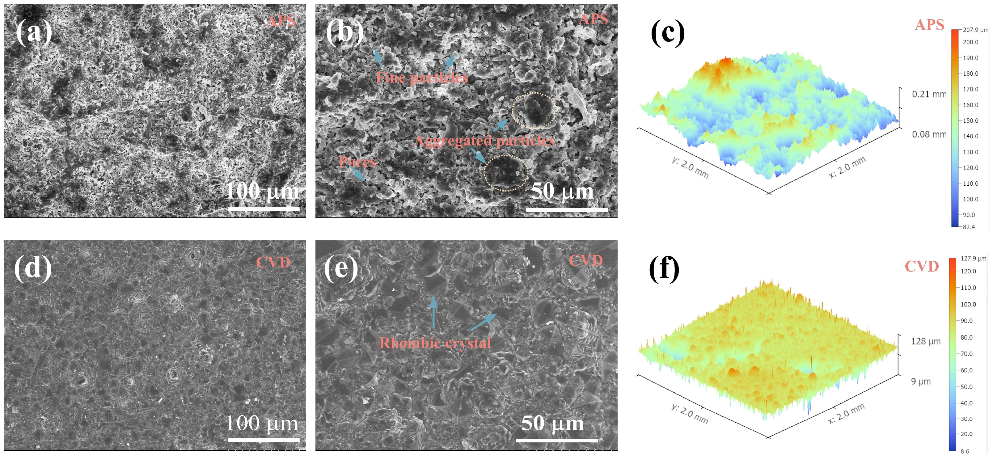
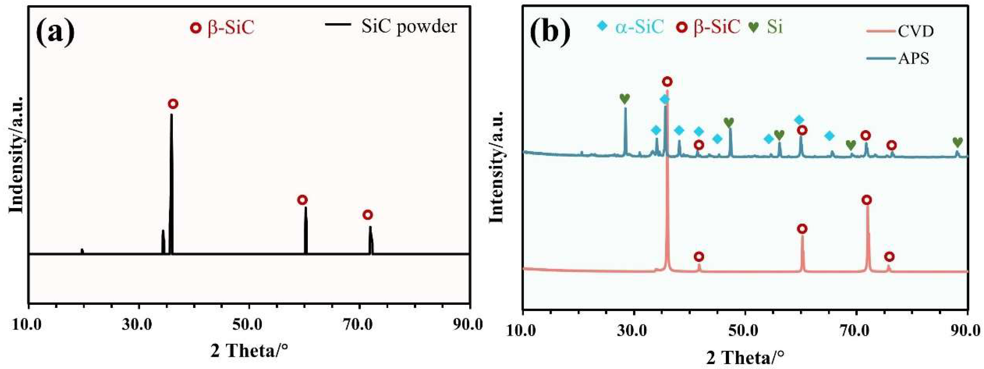
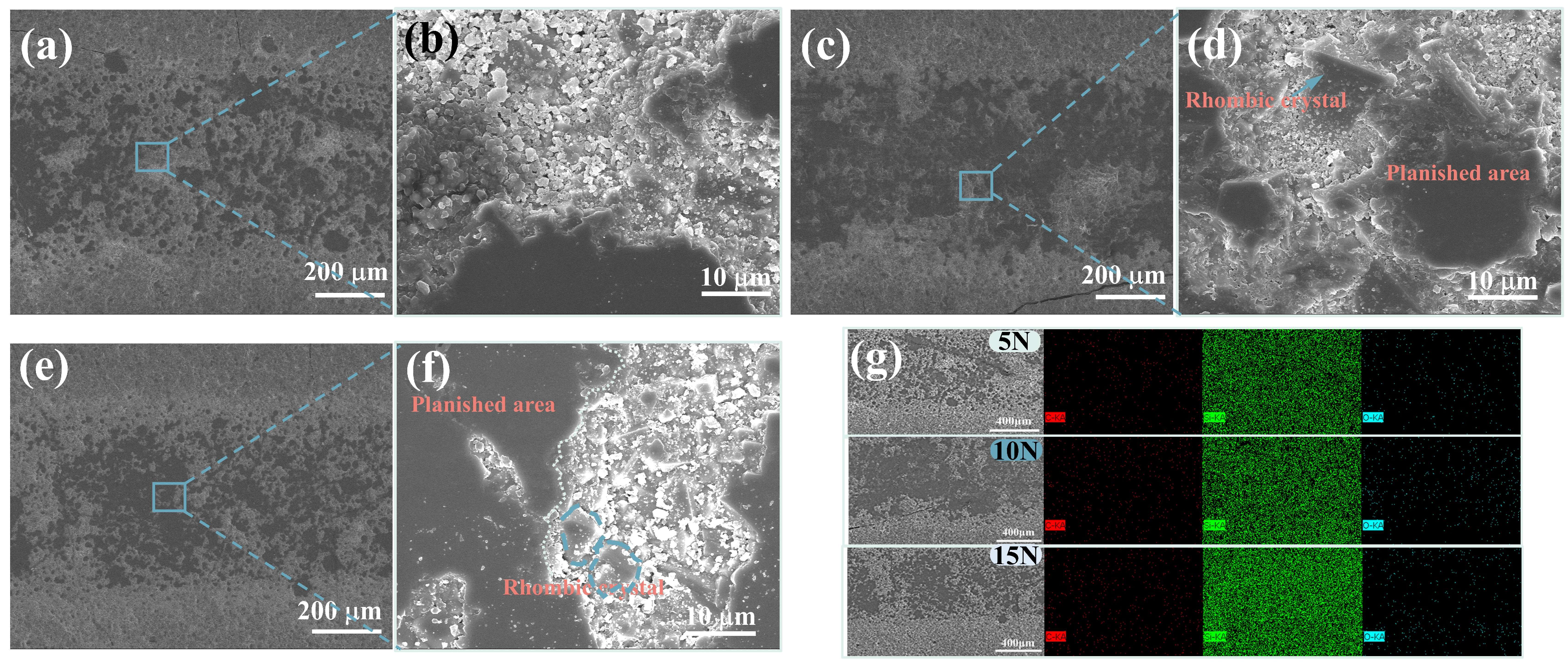
The surface morphology of the APS-SiC coating was characterized by a porous structure, while the CVD-SiC coating displayed a surface composed of many pyramidal-shaped crystals. The APS-SiC coating is predominantly composed of the α-SiC phase, with a small fraction of the Si phase, whereas the XRD pattern of the CVD-SiC coating is primarily indicative of the β-SiC phase.
(2)
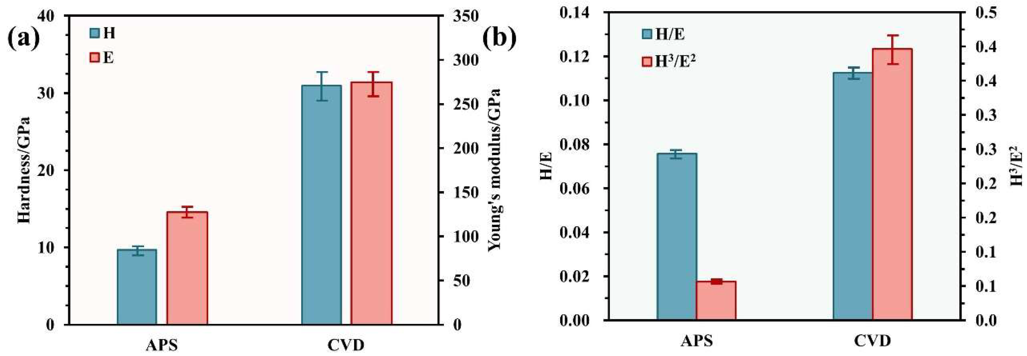
The hardness and Young’s modulus of the CVD-SiC coating were 31.0 GPa and 275 GPa, respectively. The higher H/E and H3/E2 parameters of the CVD-SiC coating suggested superior plastic resistance, which is also significant for its anti-wear properties. The critical loads for the spallation of the APS-SiC coating and CVD-SiC coating were determined to be approximately 25.9 N and 36.4 N, respectively, indicating that the CVD-SiC coating possesses greater adhesive strength.
(3)
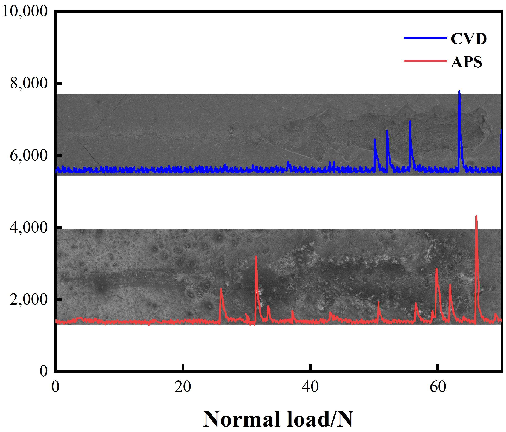
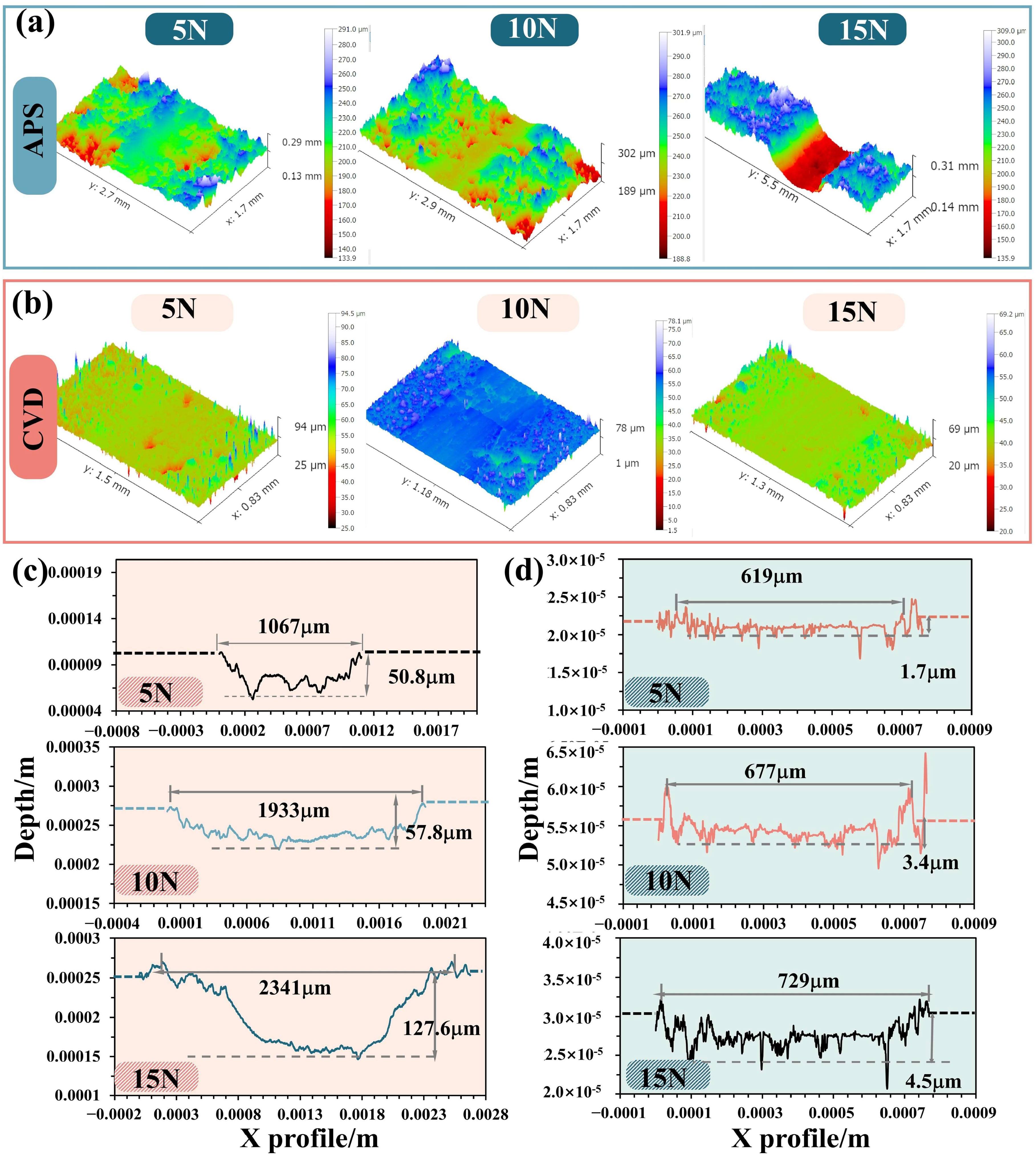
During the tribological test, the friction coefficient of the APS-SiC coating exhibited significant fluctuations under high load conditions due to the damage to the SiC coating. The CoF of CVD-SiC was higher than that of the APS-SiC coating at loads of 5 and 10 N, but it stabilized at approximately 0.2 at 15 N. The wear morphology of the APS-SiC coatings under all tested loads revealed numerous cracks and wear debris, indicating that abrasive and fatigue wear were the dominant mechanisms. In contrast, the worn tracks of the CVD-SiC coating showed planished asperities and some untouched areas. The wear rate of the CVD-SiC coating was significantly lower than that of the APS-SiC coating, suggesting the superior wear resistance of the CVD-SiC coating.

Author Contributions

Conceptualization, H.L.; Methodology, Y.Q., J.G., X.C. and H.L.; Software, F.J.; Validation, Y.Q. and J.G.; Formal analysis, Q.M.; Investigation, J.G., Q.M. and X.C.; Data curation, F.J.; Writing—original draft, Y.Q.; Writing—review & editing, F.J., X.C. and H.L.; Supervision, W.L.; Project administration, W.L.; Funding acquisition, W.L. and H.L. All authors have read and agreed to the published version of the manuscript.

Funding

This work was funded by the National Major Science and Technology Projects of China (Y2022-III-0004-0013), the National Natural Science foundation of China (Grant No. 52272065), the Opening Fund of Key Laboratory of Rare Earths, Chinese Academy of Sciences (No. E32PF00115), and the Opening Fund of the Wuxi Research Institute, Nanjing University of Aeronautics and Astronautics (No. KFKT20230202).

Data Availability Statement

The original contributions presented in the study are included in the article, further inquiries can be directed to the corresponding author. The data presented in this study are available on request from the corresponding author. The data are not publicly available due to the data also forms part of an ongoing study.

Conflicts of Interest

The authors declare no conflict of interest.

References

  1. Huang, J.; Guo, L. SiC coating with high crack resistance property for carbon/carbon composites. Ceram. Int. 2022, 48, 1740–1744. [Google Scholar] [CrossRef]
  2. Kang, K.; Yu, B.; Deng, G.; Wang, P.; Yin, J.; Zhang, H.; Luo, G.; Song, H. Effect of counterpart materials on tribological behaviors of copper impregnated carbon/carbon composite under electric current condition. Ceram. Int. 2023, 49, 30008–30018. [Google Scholar] [CrossRef]
  3. Buchgraber, W. Carbon/Carbon Composite Friction Discs for Aerospace. Mater. Und Werkst. 2003, 34, 317–321. [Google Scholar] [CrossRef]
  4. Kogo, Y.; Iijima, Y.; Igata, N.; Ota, K.I. Internal friction of carbon–carbon composites at elevated temperatures. J. Alloys Compd. 2003, 355, 148–153. [Google Scholar] [CrossRef]
  5. Ju, C.P.; Lin, J.C.; Lee, K.J.; Kuo, H.H. Mulyi-braking tribological behavior of PAN-pitch, PAN-CVI and pitch-resin-CVI carbon-carbon composites. Mater. Chem. Phys. 2000, 64, 196–214. [Google Scholar] [CrossRef]
  6. Kasem, H.; Bonnamy, S.; Berthier, Y.; Dufrénoy, P.; Jacquemard, P. Tribological, physicochemical and thermal study of the abrupt friction transition during carbon/carbon composite friction. Wear 2009, 267, 846–852. [Google Scholar] [CrossRef]
  7. Kasem, H.; Bonnamy, S.; Rousseau, B.; Estrade-Szwarckopf, H.; Berthier, Y.; Jacquemard, P. Interdependence between wear process, size of detached particles and CO2 production during carbon/carbon composite friction. Wear 2007, 263, 1220–1229. [Google Scholar] [CrossRef]
  8. Feng, L.; Guo, L.; Chen, Q.; Tian, R.; Zhang, J.; Song, Q.; Wei, P.; Xiao, C.; Fu, Q. Tailoring the geometry of silicon nitride nanofillers to simultaneously strengthen and toughen carbon/carbon composites. J. Mater. Sci. Technol. 2024, 202, 183–191. [Google Scholar] [CrossRef]
  9. Zishan, C.; Hejun, L.; Qiangang, F.; Yanhui, C.; Shaolong, W.; Zibo, H. Tribological behavior of SiC coating on C/C composites against SiC and WC under unlubricated sliding. Ceram. Int. 2013, 39, 1765–1773. [Google Scholar] [CrossRef]
  10. Kumar, P.; Srivastava, V.K. A Review on Wear and Friction Performance of Carbon–Carbon Composites at High Temperature. Int. J. Appl. Ceram. Technol. 2016, 13, 702–710. [Google Scholar] [CrossRef]
  11. Zhu, X.; Zhang, Y.; Su, Y.; Fu, Y.; Zhang, P. SiC-Si coating with micro-pores to protect carbon/carbon composites against oxidation. J. Eur. Ceram. Soc. 2021, 41, 114–120. [Google Scholar] [CrossRef]
  12. Wu, Q.; Yu, S.; Zhong, H.; Li, X.; Xiao, T.; Liu, L.; Guo, X.; Li, Y.; Nie, Y. Preparation of silicon carbide coating by chemical vapor deposition by using hexamethyldisilylamine precursor. Surf. Coat. Technol. 2018, 334, 78–83. [Google Scholar] [CrossRef]
  13. Liu, Y.; Miao, Q.; Liang, W.; Lin, H.; Ma, H.; Shi, W.; Xu, X. Effect of Al2O3 addition on the microstructure and oxidation behavior of SiC coating prepared by pack cementation on C/C composites. Ceram. Int. 2021, 47, 29309–29319. [Google Scholar] [CrossRef]
  14. Huang, J.-F.; Zeng, X.-R.; Li, H.-J.; Xiong, X.-B.; Fu, Y.-W. Influence of the preparation temperature on the phase, microstructure and anti-oxidation property of a SiC coating for C/C composites. Carbon 2004, 42, 1517–1521. [Google Scholar]
  15. Yang, X.; Huang, Q.; Su, Z.; Chai, L.; Wang, X.; Zhou, L. A double layer nanostructure SiC coating for anti-oxidation protection of carbon/carbon composites prepared by chemical vapor reaction and chemical vapor deposition. Ceram. Int. 2013, 39, 5053–5062. [Google Scholar] [CrossRef]
  16. Li, N.; Wang, K.; Xu, T.; Gao, J.; Wang, Y.; Wang, W.; Sun, H. Effect of rapid thermal annealing on microstructure, mechanical and tribological properties of amorphous SiC hard coatings. J. Non-Cryst. Solids 2024, 632, 122939. [Google Scholar] [CrossRef]
  17. Das, M.; Balla, V.K.; Basu, D.; Bose, S.; Bandyopadhyay, A. Laser processing of SiC-particle-reinforced coating on titanium. Scr. Mater. 2010, 63, 438–441. [Google Scholar] [CrossRef]
  18. Li, Y.; Zheng, G.; Bi, Y.; He, J.; Qin, Y.; Yin, F.; Zhao, H. Plasma sprayed TiC–Ti5Si3–Ti3SiC2–SiC composite coatings using annealed Ti–SiC composite powders based on SiC content. Ceram. Int. 2023, 49, 11433–11441. [Google Scholar] [CrossRef]
  19. Amanov, A.; Karimbaev, R. Effect of surface engineering on wear and fatigue behavior of thermally sprayed SiC coating. Surf. Coat. Technol. 2022, 445, 128751. [Google Scholar] [CrossRef]
  20. Zhou, L.; Fu, Q.; Hu, D.; Wei, Y.; Tong, M.; Zhang, J. Oxidation protective SiC-Si coating for carbon/carbon composites by gaseous silicon infiltration and pack cementation: A comparative investigation. J. Eur. Ceram. Soc. 2021, 41, 194–203. [Google Scholar] [CrossRef]
  21. Mubarok, F.; Espallargas, N. Tribological behaviour of thermally sprayed silicon carbide coatings. Tribol. Int. 2015, 85, 56–65. [Google Scholar] [CrossRef]
  22. Krenkel, W.; Heidenreich, B.; Renz, R. C/C-SiC Composites for Advanced Friction Systems. Adv. Eng. Mater. 2002, 4, 427–436. [Google Scholar] [CrossRef]
  23. Chen, Z.; Chen, Y.; Dong, D.; Yang, Q.; Hu, M. Tribological performance of SiC coating for carbon/carbon composites at elevated temperatures. Ceram. Int. 2018, 44, 11233–11238. [Google Scholar] [CrossRef]
  24. Berdoyes, I.; Plaisantin, H.; Danet, J.; Lepetitcorps, Y.; Roger, J. The corrosion behavior of various CVD SiC coatings in molten silicon. Ceram. Int. 2024, 50, 3877–3886. [Google Scholar] [CrossRef]
  25. Hao, K.; Huo, C.; Tu, J.; Sun, L.; Zhang, F.; Li, A.; Du, S. Cl2 corrosion resistance of SiC coatings with different morphologies. Mater. Today Commun. 2024, 39, 108997. [Google Scholar]
  26. Zhang, Y.-T.; Chen, G.-H.; Sun, J.; Shi, X.-H.; Li, N.; Li, H.-J. Atomic simulation and experimental: Oxidation protective SiC coating produced by chemical vapor deposition and pack cementation for carbon/carbon composites. Surf. Interfaces 2024, 46, 104170. [Google Scholar] [CrossRef]
  27. Tang, Z.; Yi, M.; Wu, H.; Zhou, Y.; Liu, R.; Jiang, J.; Peng, K. A novel approach for preparing a SiC coating on a C/C-SiC composite by slurry painting and chemical vapor reaction. J. Eur. Ceram. Soc. 2022, 42, 1884–1892. [Google Scholar] [CrossRef]
  28. Katsui, H.; Shimoda, K.; Hotta, M. Preparation of silicon carbide and tantalum carbonitride composite with high hardness and moderate elastic modulus by laser chemical vapor deposition for anti-erosion protective coatings. Ceram. Int. 2023, 49, 38813–38823. [Google Scholar] [CrossRef]
  29. Musil, J. Hard nanocomposite coatings: Thermal stability, oxidation resistance and toughness. Surf. Coat. Technol. 2012, 207, 50–65. [Google Scholar] [CrossRef]
  30. Amanov, A.; Berkebile, S.P. Enhancement of sliding wear and scratch resistance of two thermally sprayed Cr-based coatings by ultrasonic nanocrystal surface modification. Wear 2023, 512–513, 204555. [Google Scholar] [CrossRef]
  31. Hogmark, S.; Jacobson, S.; Larsson, M. Design and evaluation of tribological coatings. Wear 2000, 246, 20–33. [Google Scholar] [CrossRef]
  32. Xu, B.; Guo, P.; Wang, Z.; Chen, R.; Ye, Y.; Shuai, J.; Wang, A.; Ke, P. Anti-wear Cr-V-N coating via V solid solution: Microstructure, mechanical and tribological properties. Surf. Coat. Technol. 2020, 397, 126048. [Google Scholar] [CrossRef]
  33. Rabinowicz, E. Friction and Wear of Materials, 2nd ed.; Wiley: Hoboken, NJ, USA, 2013. [Google Scholar]
  34. Federici, M.; Menapace, C.; Moscatelli, A.; Gialanella, S.; Straffelini, G. Effect of roughness on the wear behavior of HVOF coatings dry sliding against a friction material. Wear 2016, 368–369, 326–334. [Google Scholar] [CrossRef]
  35. Podgursky, V.; Adoberg, E.; Surženkov, A.; Kimmari, E.; Viljus, M.; Mikli, V.; Hartelt, M.; Wäsche, R.; Šíma, M.; Kulu, P. Dependence of the friction coefficient on roughness parameters during early stage fretting of (Al,Ti)N coated surfaces. Wear 2011, 271, 853–858. [Google Scholar] [CrossRef]
  36. Chang, K.; Dong, Y.; Zheng, G.; Jiang, X.; Yang, X.; Cheng, X.; Liu, H.; Zhao, G. Friction and wear properties of TiAlN coated tools with different levels of surface integrity. Ceram. Int. 2022, 48, 4433–4443. [Google Scholar] [CrossRef]
  37. Perfilyev, V.; Moshkovich, A.; Lapsker, I.; Laikhtman, A.; Rapoport, L. The effect of vanadium content and temperature on stick–slip phenomena under friction of CrV(x)N coatings. Wear 2013, 307, 44–51. [Google Scholar] [CrossRef]
Figure 1. Surface morphology of APS-SiC coating (ac) and CVD-SiC (df).
Lubricants 12 00301 g001
Figure 2. Cross-sectional morphology and element analysis of APS-SiC coating (ac) and CVD-SiC coating (df).
Lubricants 12 00301 g002
Figure 3. XRD patterns of (a) SiC powder and (b) as-prepared APS-SiC and CVD-SiC coatings.
Lubricants 12 00301 g003
Figure 4. H, E, H/E, and H3/E2 parameters for (a) APS-SiC coating and (b) CVD-SiC coating.
Lubricants 12 00301 g004
Figure 5. Scratch morphologies and EDS analysis of (a) APS-SiC and (b) CVD-SiC coatings.
Lubricants 12 00301 g005
Figure 6. The curves of acoustic signal versus applied load in the scratch test for APS-SiC and CVD-SiC coatings.
Lubricants 12 00301 g006
Figure 7. Friction coefficient curves of (a) APS-SiC coating and (b) CVD-SiC coating under different loads.
Lubricants 12 00301 g007
Figure 8. Worn track morphology of APS-SiC coating under different loads: (a,b) 5 N; (c,d) 10 N; and (e,f) 15 N. (g) EDS map of wear track.
Lubricants 12 00301 g008
Figure 9. Worn track morphology of CVD-SiC coating under different loads: (a,b) 5 N; (c,d) 10 N; and (e,f) 15 N. (g) EDS map of wear track.
Lubricants 12 00301 g009
Figure 10. Three-dimensional morphology of wear tracks of (a) APS-SiC coating and (b) CVD-SiC coating, and the depth profile of wear tracks of (c) APS-SiC coating and (d) CVD-SiC coating at different loads.
Lubricants 12 00301 g010
Figure 11. Wear volume and specific wear rate of (a) APS-SiC and (b) CVD-SiC coating under different loads.
Lubricants 12 00301 g011
Table 1. Detailed processing parameters for the preparation of the APS-SiC coating.
Current
/A
Voltage
/V
Spray Distance
/mm
Plasma Gas (Ar)
/L·min−1
Plasma Gas (H2)
/L·min−1
APS600901004010
Disclaimer/Publisher’s Note: The statements, opinions and data contained in all publications are solely those of the individual author(s) and contributor(s) and not of MDPI and/or the editor(s). MDPI and/or the editor(s) disclaim responsibility for any injury to people or property resulting from any ideas, methods, instructions or products referred to in the content.

