Article

The Influence of a Lubricant Medium on the Development of Fretting Wear in an Interference Fit Connection

1
Department of Transport and Handling Machines, Faculty of Mechanical Engineering, University of Zilina, Univerzitná 1, 010 26 Žilina, Slovakia
2
Faculty of Engineering Sciences, State University of Applied Sciences in Nowy Sącz, 1a Zamenhofa Street, 33-300 Nowy Sącz, Poland
3
Department of Vehicles and Engines, Faculty of Mechanical Engineering, Technical University of Liberec, Studentská 1402, 46117 Liberec, Czech Republic
*
Author to whom correspondence should be addressed.
Lubricants 2024, 12(9), 327; https://doi.org/10.3390/lubricants12090327
Submission received: 8 August 2024 / Revised: 8 September 2024 / Accepted: 18 September 2024 / Published: 23 September 2024

Abstract

:
Fretting wear is a phenomenon occurring in many engineering objects, including push fit connections. In view of a large number of factors conducive to wear development, it is difficult to describe the mechanism of wear initiation and development. Therefore, various methods are sought to limit wear development. The use of a lubricant may be one of those ways. The aim of this article is to present the results of testing the influence of a lubricant medium on the development of fretting wear in interference fit connections. As a lubricant medium, MoS2 and Whitmore greases were used. For that purpose, wear tests were first conducted on the shaft/sleeve tribological kinematic pair, and then observations and laboratory measurements were performed. The observations demonstrated the presence of fretting wear traces on all tested samples, irrespective of the tribological kinematic pair being tested. The main kind of damage consisted of material build-ups which, during operation, become oxidised and, while moving along the connection, caused local abrasion and micropits. The best results in restricting the development of fretting wear were achieved with Whitmore grease.

1. Introduction

Fretting wear is a phenomenon that commonly occurs in many engineering objects [1,2], and this is so because of the conditions which must be met to induce it. In order for this phenomenon to occur, there must be contact between two surfaces on which forces (loads) act and the occurrence of oscillatory tangential displacements of small amplitude between the surfaces [3,4]. These are, therefore, conditions that every device in operation meets. Consequently, numerous descriptions of the occurrence of fretting wear can be found in the literature. Among other issues, the authors of these works investigate the mechanism of wear development, identify factors promoting it or, finally, propose methods to limit wear development. For example, fretting wear occurs in aeroplane and helicopter components. In this case, wear is most commonly found in aircraft engines [5], in riveted connections between wing components [6] and in splined couplings [7]. This is due to the fact that both on the ground and during the flight, the loads on aircraft components result in the rise of variable loads, where significant stress concentrations are generated. Several adverse phenomena are produced that are intensified by secondary bending, with such phenomena including plastic deformation and abrasive fatigue. Fretting wear is also noted in orthopaedic components that fix fractured limbs, in endoprostheses, in dental implants and in orthodontic appliances [8,9]. In the human organism, there are specific conditions that create a highly corrosive environment. In addition, humans perform a large number of movements, which means that tens of thousands of impulses with an excitation frequency of approximately 1 Hz may occur per day. Fretting wear is also found in roller and slide bearings [10,11], combustion engine components, electrical contacts [12,13,14] and bolted connections, as well as in steel ropes used in mines, in heat exchanger pipes and in wind turbines [15,16]. Fretting wear is present not only in metal components, but also in those made of rubber [17,18] and plastic [19].
In addition to the sample occurrences of fretting wear mentioned above, it is also appropriate to point out push fit connections, which are very often used to connect various components of machinery operating in various conditions [20,21]. The widespread use of this type of connection mainly follows from its advantages, which include the ease and the low cost of its assembly process, especially in the case of interference fit connections. Meanwhile, there are few articles available in the literature that deal with the assessment of fretting wear in this type of connection operating especially in rotational bending conditions. The shaft/sleeve push fit connection accumulates in it all the factors necessary for the development of fretting wear. First, there is constant pressure between the surfaces of the components joined together. Second, if the connection operates in rotational bending conditions, relative displacement between these surfaces occurs.
The small number of investigations carried out on wear in push fit connections can be explained by difficulties in observing such wear. Connection disassembly may involve destroying the resulting wear image and thus make it impossible to analyse it accurately, and the quantitative assessment of wear is also difficult. For example, in order to determine the intensity of wear development depending on the number of cycles, each time, it would be necessary to disassemble and reassemble the connection by force, which would certainly cause additional surface damage.
One example of an interference fit connection to which special attention should be paid is the wheel/axle connection of a rail vehicle wheel set [22]. The importance of that subassembly in the vehicle is stressed here [23]. Namely, that subassembly keeps the vehicle on its tracks and is directly responsible for travel safety, as a defect or damage may lead to a collision situation. However, the operating conditions, which include vertical loads from the vehicle weight, lateral forces at the wheel flange/rail head contact area resulting from hunting oscillation of the vehicle and dynamic forces at the wheel/rail contact area, cause the wheel set axle to deform, thus leading to relative slips between the wheel hub surface and the axle seat [24,25]. This adverse effect of external forces and its state of stress due to tolerance lead to wear and damage in the axle.
Fretting comprises various kinds of wear and damage, but their kind, extent and intensity depend on contributing factors. In the analysis of fretting wear, both in push fit connections and other engineering objects, three main groups of factors conducive to wear development are taken into consideration. One group comprises factors related to the properties of the material from which the mating elements are made. In this case, surface hardness, adhesion properties, fatigue strength, tensile strength and susceptibility to corrosion may turn out to be significant. The next group of factors is related to ambient conditions, in particular air temperature, humidity and pollution, as well as to lubrication conditions. The third group of factors conducive to fretting wear development are those related to the conditions of tangential displacement oscillation, which are affected by, for example, the load on the tribological kinematic pair, vibration amplitude and frequency, and the number of cycles.
Wear may also take place as a result of one or more mechanisms, depending on various factors [26]. As a result of vibration, wear products behave differently—they may accumulate, fill microholes or be removed from the wear zone, which are also of major significance for the development of fretting [27]. Hence, it is difficult to describe the single mechanism of initiation and development of fretting wear and suggest ways to restrict its development. Fretting wear may result in connection loosening, connection seizure or the appearance of fatigue cracks [28].
In the case of push fit connections, examples of tests may be found which pertain to the use of various processes such as finish rolling, surface hardening and nitriding to eliminate wear development. The use of thin Physical Vapour Deposition (PVD) coatings was also analysed. None of those methods, however, yielded the expected results. Fretting wear was less intensive, but not fully eliminated.
The hope to improve the situation is to use a lubricant medium with specific properties to eliminate the option for fretting wear to develop. Fretting wear behaviour under oil lubricants is of great practical significance since oil is usually used to regulate the fretting regime for minimising wear [29]. The aim of this article is therefore to assess the condition of the top layer of components of the interference fit connection in terms of fretting wear with the use of selected lubricant media. MoS2 and Whitmore greases were used as lubricants. The benefits of using these greases are discussed later in this article. These greases are widely used in various industries, especially railways. However, they are not used as a preventive measure to limit the development of fretting wear in pressed-in joints. There are no publications in the literature that prove such a use, and these research results may be promising. This is important, especially in the case of pressed-in joints that are heavily loaded and have a direct impact on safety. An example of this would be the wheel sets of rail vehicles. Here, any method of limiting fretting wear has a significant impact on the quality of the connection.

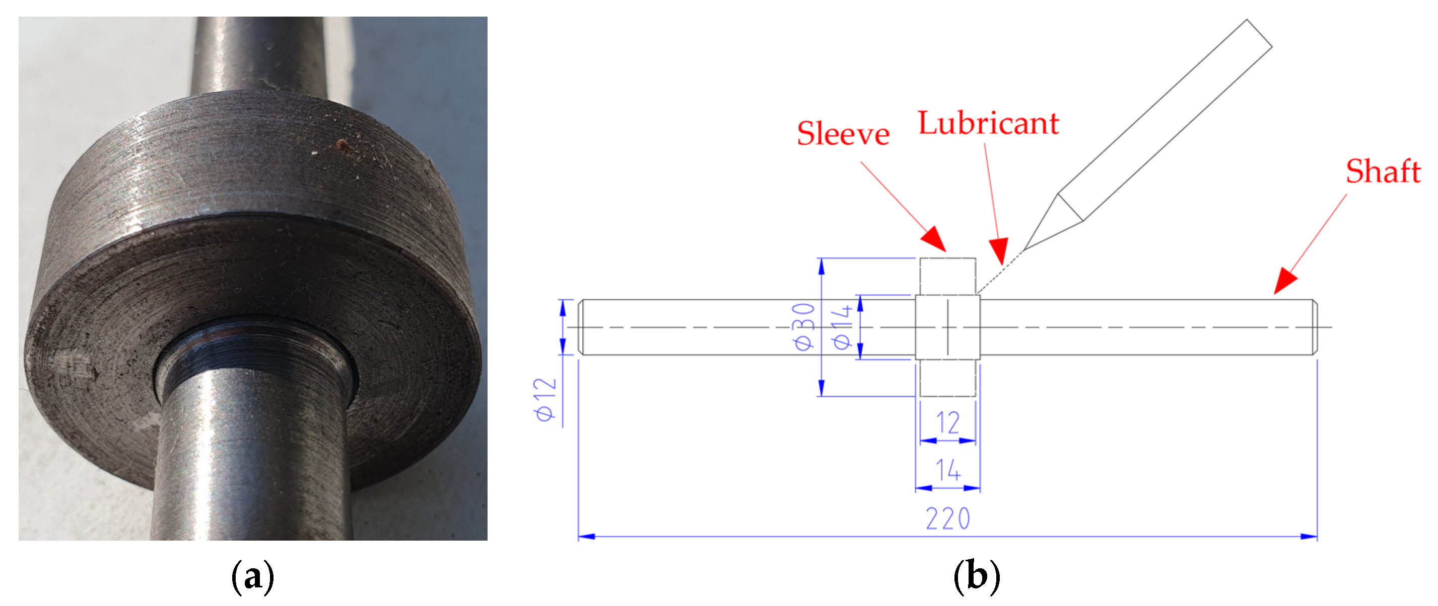
2. Materials and Methods

The object of the tests whose results are presented in this article is the tribological kinematic pair consisting of a shaft and sleeve. Figure 1 shows the general view of the tribological kinematic pair and its dimensioned sketch.
In order to set a tone of practicality for this research, the dimensional similarity of the mating connection components was maintained, particularly with regard to the diameter, connection length and tolerance values. Owing to that, test results will be transferable with a high degree of probability to objects of considerably larger dimensions and operating under similar conditions, objects for which it would be technologically and economically complex and time-consuming to conduct similar tests. An example of such an object would be a rail vehicle wheel set.
The components are made of C35 steel, whose chemical composition and mechanical properties are presented in Table 1 and Table 2. The input parameters of the mating components are summarised in Table 3.
The tribological kinematic pair was assembled with the use of the forcing process for which the tolerance value of 0.03 mm was taken. An important point to take into account when carrying out the forcing process is the use of an appropriate tolerance value that will ensure the durability of the connection when external forces are applied. Therefore, the adopted tolerance value was verified by strength analysis using surface pressure values, where the value of the surface pressures was assessed. The analysis showed that the value of these pressures was 140.9 MPa, which meets the requirements for this type of connection with the assumed sleeve and shaft dimensions. It is therefore possible to conduct the wear tests with full safety without the risk of the connection becoming disconnected during the tests.
Before assembling the connection, two different lubricant media were introduced between the mating components; those media, according to the authors of this paper, will help to improve the tribological properties of the pair in question and eliminate, or at least reduce, fretting. As the lubricant media, MoS2 and Whitmore greases were used, whose basic technical parameters are summarised in Table 4. Both kinds of grease are used in railway engineering to protect the selected assemblies and have a positive effect.
MoS2 prevents the oxidation and excessive wear of mechanical parts, thus ensuring their long-term lubrication in a very wide range of temperatures. That grease protects the components from corrosion, load, friction and dust.
Whitmore is most often used in automatic trackside bend rail and point blade lubricating systems, and in wheel sets. This grease is distinguished by good lubricating properties.
Wear tests were conducted on a fatigue testing machine enabling a periodically variable load to be obtained by pure bending of a rotating sample. The way of fixing and the load on the tribological kinematic pair were designed to enable the appropriate distribution of the bending moment, which will cause shaft deflection and the occurrence of an amplitude of oscillatory tangential displacements between the surfaces joined together, which is a necessary condition for the initiation and development of fretting wear. Similar operating conditions are found in the case of rail vehicle wheel sets, which is another argument for the transferability of the results of these tests carried out under laboratory conditions to the real object. Table 5 summarises the parameters of the fatigue tests of the tribological kinematic pair on the fatigue testing machine.
Following the completion of the fatigue tests, the samples were prepared, which were subjected to observations and laboratory tests to determine the influence of the proposed lubricant media on the development of fretting wear in an interference fit connection. An appropriate tribological kinematic pair-cutting procedure was required for sample preparation. Sleeve removal from the shaft by means of a hydraulic press was not acceptable, as such a situation would lead to the destruction of the image of the wear which appeared during the fatigue tests. The detailed sample-cutting procedure can be found in, for example, [30,31,32]. A diagram with the sequence of steps related to the observation and measurements of wear on the shaft surface after the wear tests is presented in Figure 2.
Finished samples were first subjected to macroscopic observations to determine the actual condition of the top layer within the sleeve/shaft connection. Then, the areas affected by wear were subjected to microscopic observations and to an analysis of the chemical composition of the wear products. The aim of the observations was to assess the kinds of wear comprised by fretting.
Follow-up tests were also conducted for a better understanding of the phenomena occurring in the top layer and on the surface of the mating components. Those tests included the measurement of surface hardness and roughness before and after wear testing. The coefficient of friction and wear intensity were also measured.

3. Results

In this chapter, the results of the observations and laboratory tests will be presented in accordance with the adopted research procedure described in the previous chapter.

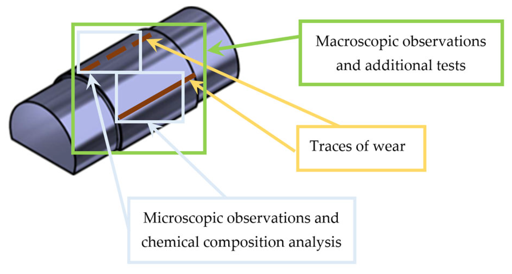
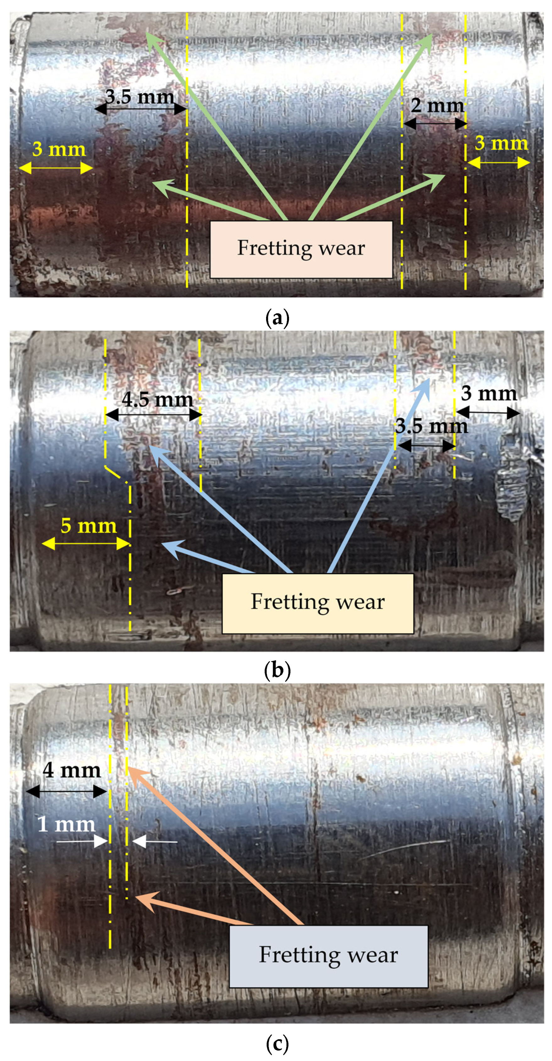
3.1. Macroscopic Observations of Shaft Surfaces

Figure 3 shows the results of the macroscopic observations of shaft surfaces after wear tests. The images of shaft surface wear for the tribological kinematic pair without a lubricant medium were compared with other shaft surfaces.
Fretting wear traces are visible on all of the tested shaft surfaces. Wear trace intensity is random and does not depend on the lubricant medium used. However, the traces of fretting can be seen on either side of the shaft surfaces each time and those traces occur mainly by the edge of the connection between the shaft and sleeve. The tribological kinematic pair with Whitmore grease is an exception, as wear traces are observed on one side of the shaft. Wear occurs at the entire axle seat circumference in the form of a ring of a variable width.
The location of fretting wear traces can be explained by the mechanism of fretting development in the push fit connections operating in rotational bending conditions. In relation to the load assumed for the tribological kinematic pair in the fatigue tests, the maximum amplitude of oscillation between the shaft and sleeve surfaces occurs at the connection edge, and is zero in the central part. Therefore, relative displacements between the two surfaces will be noticeable at the connection edges. That situation will result in the removal of wear products to the outside of the connection, due to which there will be direct contact between the mating surfaces. This creates favourable conditions for the development of adhesive bonds, which in turn lead to the destruction of the top layer.
The wear traces noted on the shaft surfaces are brown, which is a typical colour of the atmospheric corrosion of steel. This image is indicative of a gap between the mating surfaces, which was created as a result of shaft deflection, allowing the damaged area to come into contact with oxygen.

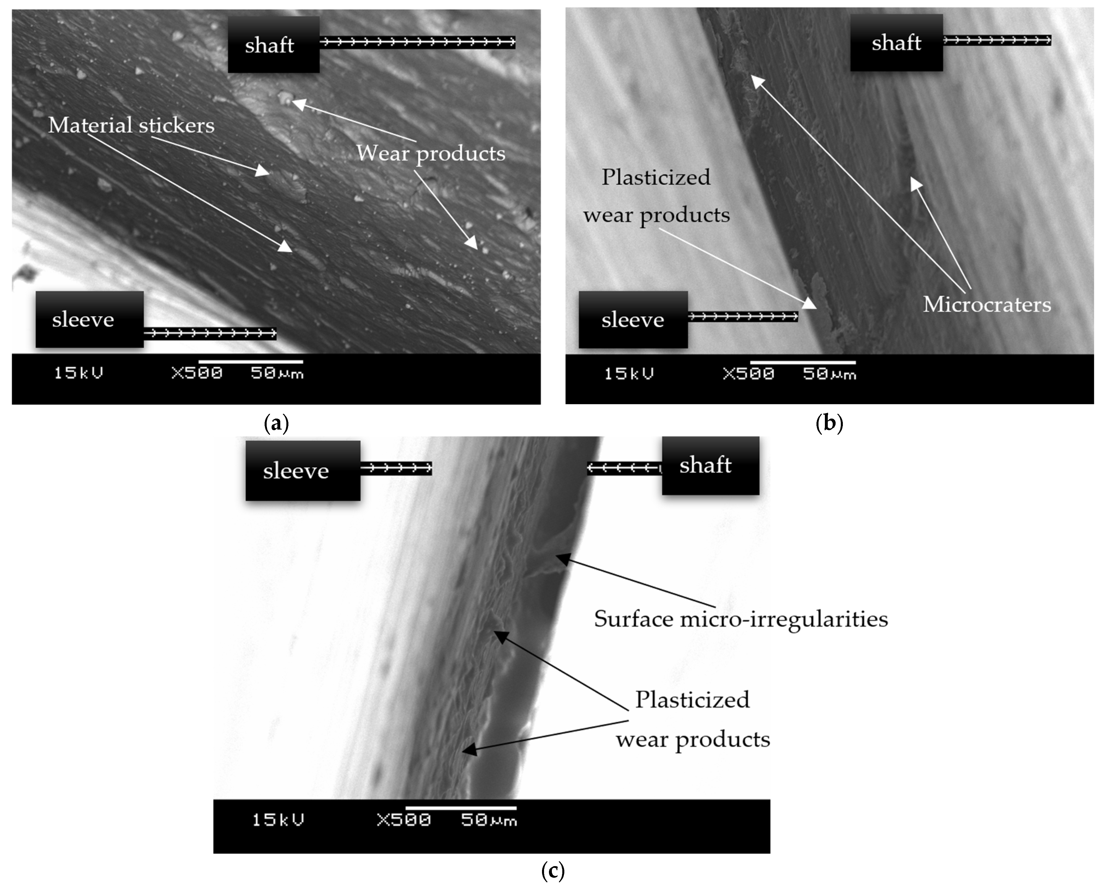
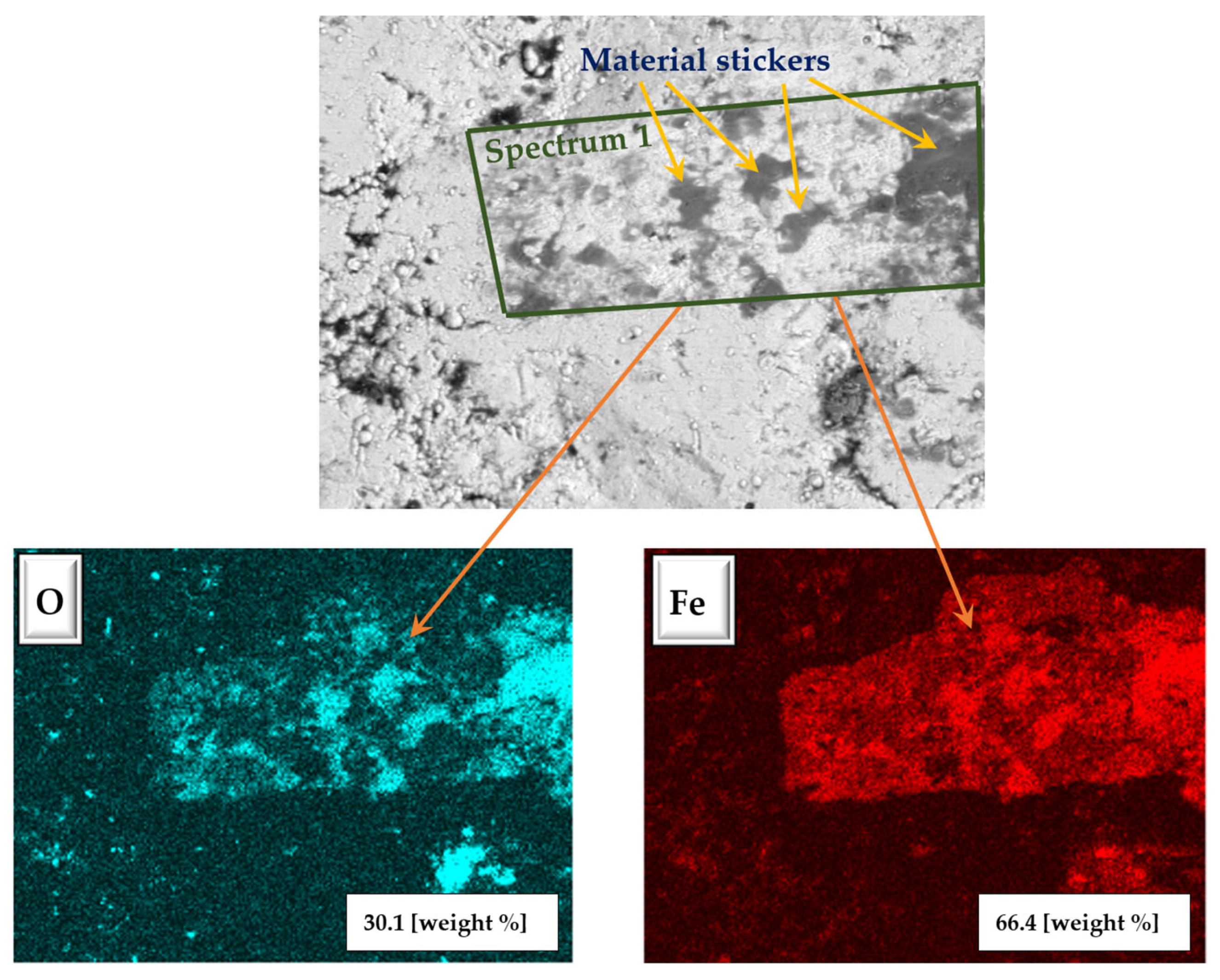
3.2. Microscopic Observations of Shaft Surfaces

Figure 4 presents electron scanning microscope images showing shaft surfaces with visible wear traces created by fretting. Figure 5 shows the images of the space between the sleeve and shaft surfaces, at which the location and form of wear products can be seen over the connection length, and the technical condition of the surfaces of the tribological kinematic pair components.
The analysis of the microscopic images enabled the assessment of the kind of damage created by fretting and of the distribution of wear products over the connection length. The picture of fretting for all the samples under observation is very similar. That picture consists of the same kinds of damage, with only their dimensions differing, depending on the type of the tribological kinematic pair being tested; therefore, the random images of wear are shown in the figure above.
The primary damage to the surface of the mating components is caused by material build-ups. They account for 80% of damage noted on all the samples. A similar picture of damage is noted in the case of both the tribological kinematic pair without a lubricant medium and with the use of the proposed greases.
In the majority of cases, the observed material build-ups are distinguished by plastic deformation and oxidation features. The process of wear product softening is linked to the presence of oscillation movements between the sleeve and shaft during fatigue tests. Cyclically moving surfaces act on the wear products like a roller, which rolls them out and sticks them to the surface, thus making up material build-ups.
The source of the wear products, which are transformed into material build-ups at a later stage, is mainly the process of forcing the sleeve onto the shaft. It is then that surface microirregularities are shorn and wear products come into being. The process continues during fatigue tests, during which wear products are formed, too.
Due to the shearing of microirregularities, craters come into being, which, during the operation of the tribological kinematic pair, are filled with wear products, thus reducing surface roughness and increasing the direct contact area between the mating elements. This may result in adhesion, which is one of the causes of adhesive bonds. These, in turn, will cause fragments of the surface to peel off, thus enhancing fretting wear.
The microscopic images also show that some plastically deformed wear products had a tendency to crack and move.
Another kind of damage to the top layer of both the sleeve and shaft is defined by local abrasion and micropits, which are caused by moving wear products distinguished by greater hardness in relation to the sleeve and shaft surfaces.
Figure 6 shows the chemical element distribution maps for shaft surfaces after wear tests. The chemical composition of wear products (material build-ups) in the fretting wear zone was analysed.
The chemical analysis of the composition of wear products, in particular material build-ups, confirmed the claim that they became oxidised during the fatigue tests. In the chemical composition of the products, also noted were the trace amounts of molybdenum (2–5 weight %) mainly originating from the lubricant medium used during the wear tests.

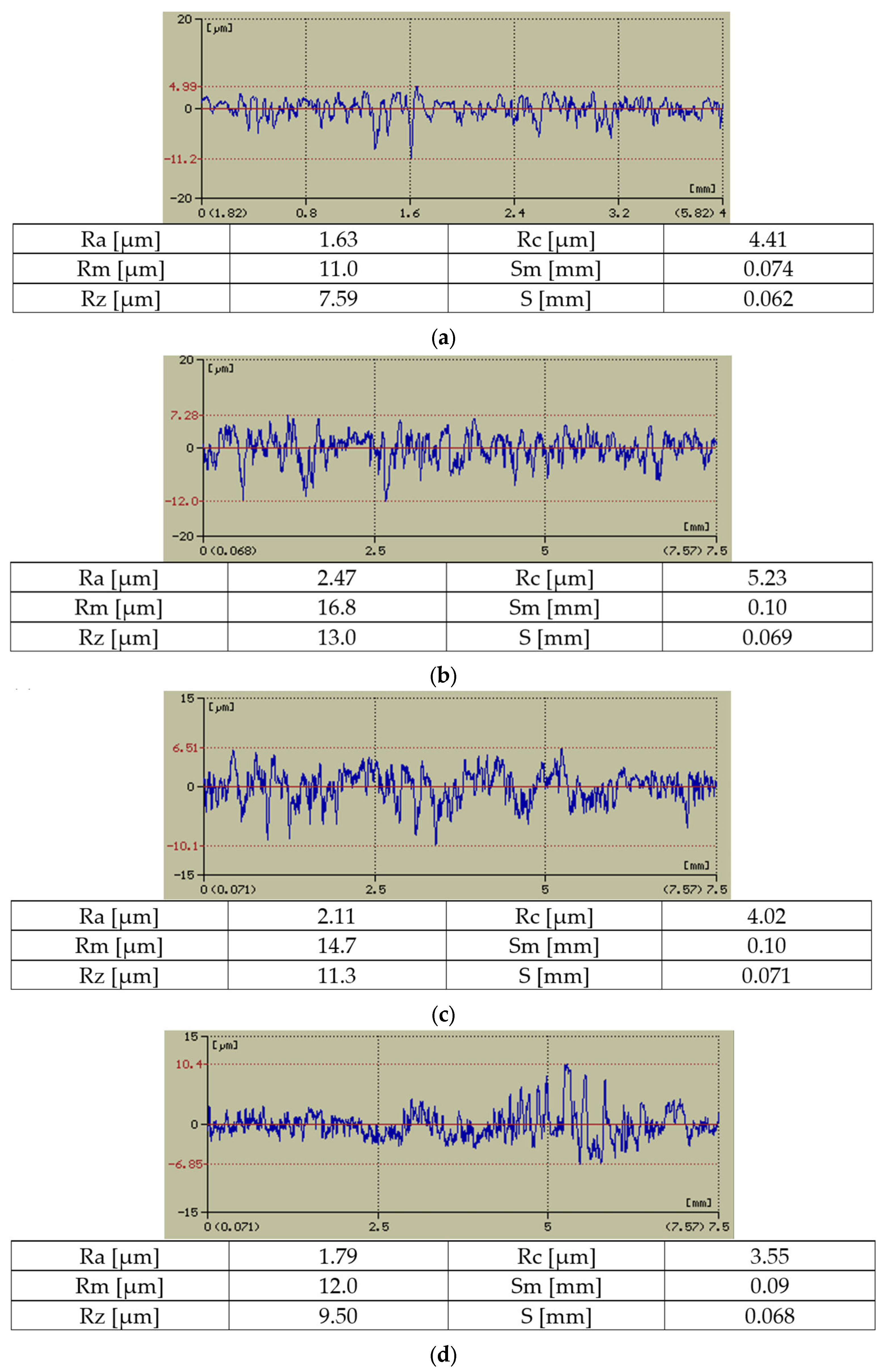
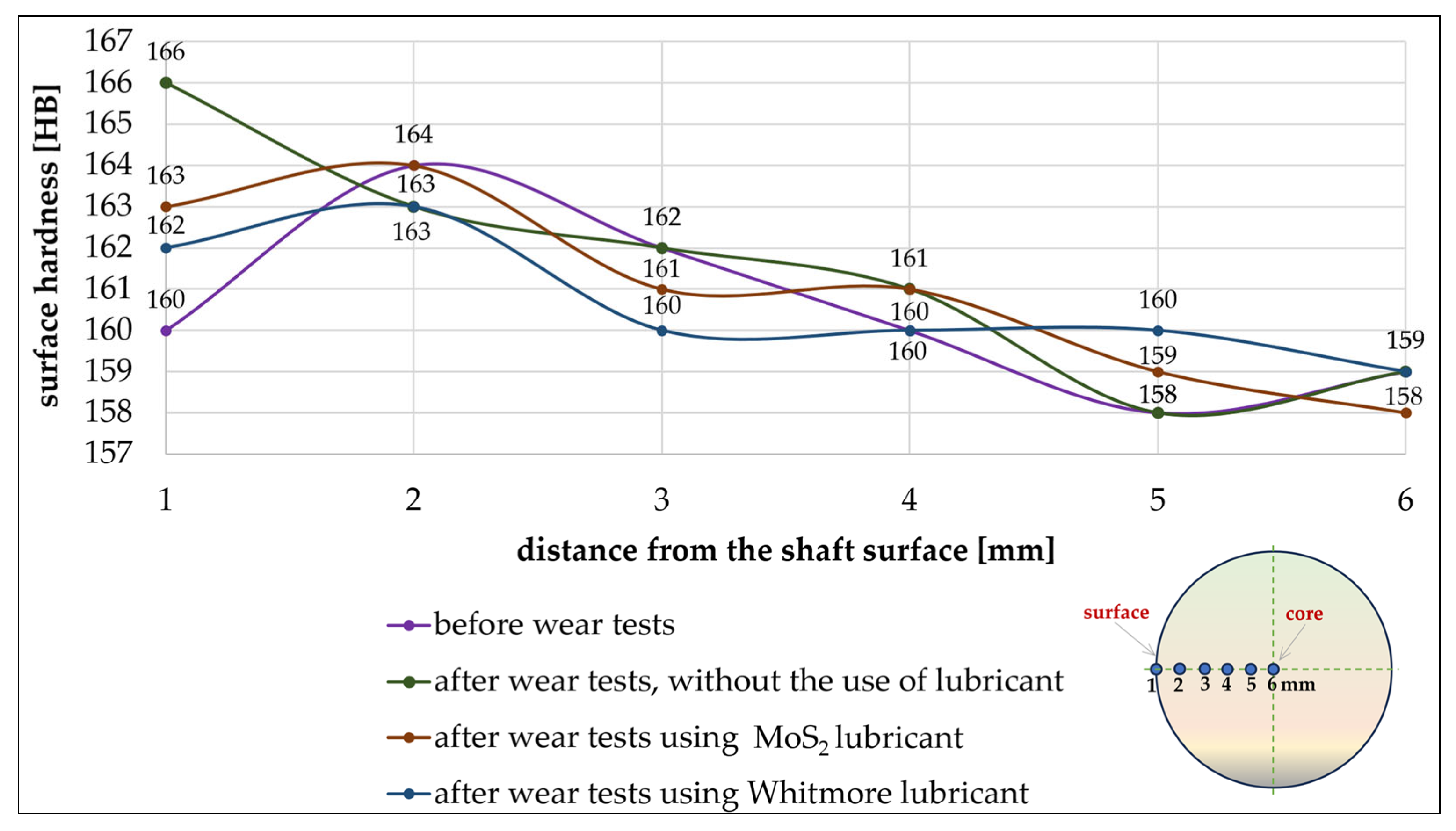
3.3. Shaft Surface Roughness and Hardness

The analysis of the surface profile of an engineering object, in particular of its roughness parameters, is one of the key elements in the fretting wear assessment.
In Figure 7, selected parameters and roughness profiles of the shaft surfaces before the wear tests and after the fatigue tests are compared.
Shaft surface roughness analysis demonstrated a change in shaft parameters after the wear tests. Based on the quoted results of parameter testing and the roughness profile diagrams, it is appropriate to conclude that shafts without a lubricant medium applied become most worn out. In that case, for example, the Ra parameter increased by 15%. That measurement provides further confirmation of the occurrence of fretting in the tribological kinematic pairs under analysis. The increase in roughness parameters is due to, among other factors, the formation of material build-ups on the shaft surfaces and to craters originating from the shearing of microirregularities present on the surfaces of the mating components.
The shaft surface roughness parameters on the tribological kinematic pair with Whitmore grease increased the least. The Ra roughness parameter increased by slightly less than 5%. When analysing the macroscopic images of the shaft surfaces, it may be noted that the surfaces which mated with each other in the Whitmore lubricant medium are distinguished by the least wear intensity, which is also reflected in their roughness parameters. A smaller amount of wear products will also form smaller areas with material build-ups and, therefore, the surface profile of those shafts will change insignificantly in relation to the surface profile of the shafts before the wear tests.
The process of forcing the sleeve onto the shaft is not insignificant, either, in terms of changing the surface roughness profile of the shafts. The use of grease with better properties, which is precisely Whitmore grease, will result in less surface damage, which will also be reflected in the subsequent destruction process during fatigue testing.
Based on surface roughness, the degree of wear on the shaft’s top layers can also be assessed; therefore, hardness tests were also performed. Figure 8 presents diagrams showing the shaft roughness change as a function of the distance from their surface to the material’s interior.
The obtained shaft hardness values do not vary significantly regardless of dry operating conditions or the use of a lubricant medium. Shaft hardness varies within the range of 160–166 HB at the surface and 158–159 HB at 6 mm from the surface.
After wear tests, shaft hardness close to the surface increased slightly. The biggest differences in value are also noted at that place. Towards the core, shaft hardness becomes stable and the values are similar.
The greatest surface hardness value of 166 HB is noted for shafts operating in dry friction conditions. The smallest hardness, however, is noted for the surfaces of the shafts operating in the tribological kinematic pair with a lubricant medium using Whitmore grease; that value is 162 HB.
Differences in the hardness of the shaft surfaces after wear tests are mainly due to the amount of wear products on their surface and the degree of oxidation of those products. Shafts operating in dry friction conditions are distinguished by the highest wear intensity and therefore, in that case, the biggest number of oxidised material build-ups is noted, which is conducive to greater surface hardness. The opposite behaviour is noted for shafts operating in a lubricant medium using Whitmore grease. In that case, wear intensity is the lowest; therefore, the smallest number of oxidised wear products influencing surface hardness is present there.

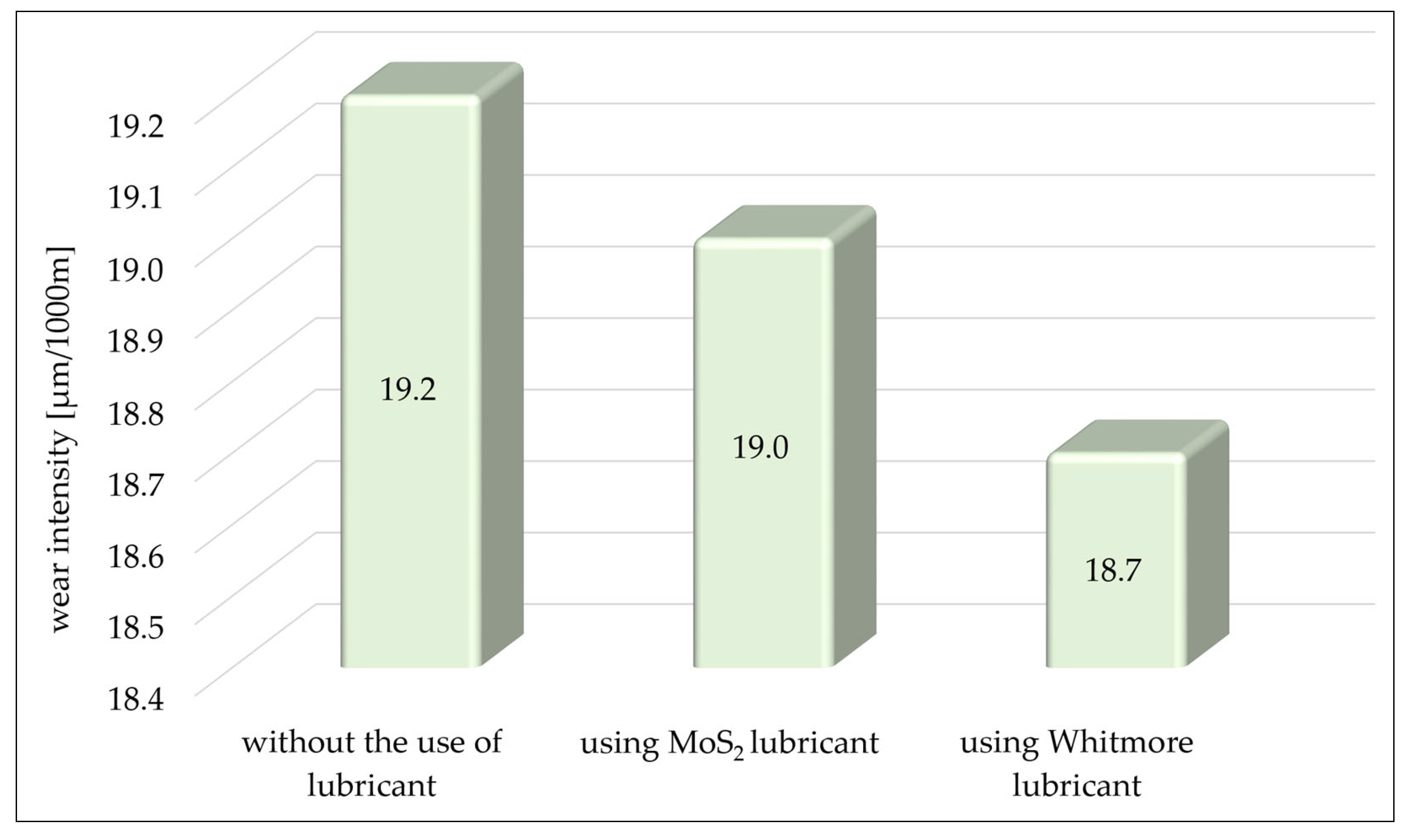
3.4. The Measurement of the Coefficient of Friction and Wear Intensity

Following wear tests, the coefficient of friction between the shaft and sleeve was determined for each sample, and the maximum values from those measurements are shown in Figure 9.
A change in the coefficient of friction in relation to the initial state (the coefficient of friction before the wear tests was µ = 0.672) is most likely influenced by wear intensity, as well as by the number and size of the material build-ups on the surface of the mating components.
The greatest value of the coefficient after the wear tests is noted for the tribological kinematic pair without the use of a lubricant medium. In the macro- and microscopic image, that surface is distinguished by the most intensive wear traces. Quite to the contrary, the tribological kinematic pair containing Whitmore grease is distinguished by the lowest coefficient of friction, its value being 0.687. It is also in that case that the lowest intensity of the wear of the top shaft layer is noted.
Based on the statements above, it may be concluded that there is a strong correlation between the value of the coefficient of friction and wear product intensity. A bigger contact area of the original surfaces may contribute to the formation of adhesive bonds, but also promotes the lower values of the coefficient of friction.
Shaft wear intensity is determined in relation to shaft surface wear and the path of friction. The results of the calculations are presented in Figure 10.
A decrease in wear intensity is noted depending on the lubricant medium applied. The shafts of the tribological kinematic pair with Whitmore grease are distinguished by the lowest wear intensity. The results obtained are supported by wear traces on the shaft surfaces, with such traces occurring only on one side of the shaft axle seat, and the wear ring width being only 1 mm.

4. Conclusions

The aim of the tests whose results are presented in this article was to assess the influence of a lubricant medium on the development of fretting wear in interference fit connections subject to a rotational bending moment.
Based on the investigations and observations, the following conclusions may be drawn:
  • The pre-set fatigue test conditions are conducive to the development of fretting wear, whose traces are noted on all the shaft surfaces under investigation. The macroscopic image of wear is formed in a similar way for all the samples and assumes the shape of a ring of various widths located at the edges of the shaft axle seat.
  • The use of MoS2 grease restricted fretting wear to a small extent. In that case, wear traces occurred at random on either side of the shaft axle seat, and the intensity of those traces was similar to the wear traces on the surfaces of the shafts operating without a lubricant medium.
  • The most advantageous effects of fretting wear reduction were achieved for the tribological kinematic pair with Whitmore grease. Its application did not eliminate wear, but reduced it effectively. In that case, wear traces were noted on one side of the shaft axle seat in the form of a ring comprising the entire shaft circumference. The ring width and wear intensity also clearly decreased.
  • The macroscopic observations demonstrated the grey/dark brown colour of the wear traces, which is typical of metal corrosion. That phenomenon was the result of the presence, in the wear zone, of oxygen, which flowed through the gap between the shaft and sleeve, the gap coming into being as a result of shaft deflection.
  • Fretting in the tribological kinematic pairs under analysis comprises mainly wear products in the form of material build-ups which become softened, oxidised and fragmented over time. Wear products hardened by oxidation as they move around cause further damage in the form of surface abrasion and micropits.
  • The amount of wear products and the degree of their oxidation influence the change in the surface profile and shaft hardness. This is confirmed by the smallest change in roughness and hardness parameters of the shafts operating in the presence of Whitmore grease among all the samples tested.
  • The coefficient of friction between the mating components, as measured after the wear tests, shows the lowest value for tribological kinematic pairs containing Whitmore grease, which is indicative of fewer material build-ups on the shaft surface. Wear intensity is similar, as was already observed at the macrographic analysis stage.
  • Among the greases analysed in these tests, Whitmore deserves attention, as this grease effectively reduced the development of fretting wear in interference fit connections subjected to a bending rotational moment. Therefore, it is recommended that that grease be used in similar cases and that more in-depth scientific research be conducted into the use of that grease a means of preventing or reducing wear and tear.
Based on the above-mentioned conclusions, it can be concluded that the phenomenon of fretting is inherent in the operation of technical facilities. Its elimination or even its significant reduction is a very difficult task facing technologists and scientists.
The research presented in this article has shown that the use of lubricant in the form of MoS2 and Whitmore greases does not solve the problem of fretting wear and a further search for new methods to eliminate it is needed.

Author Contributions

Conceptualisation, D.B., S.K., J.D. and A.D.; methodology, D.B., S.K., J.D. and A.D.; formal analysis, D.B., S.K., J.D. and A.D.; investigation, D.B., S.K., J.D. and A.D; data curation, D.B., S.K., J.D. and A.D.; writing—original draft preparation, D.B., S.K., J.D. and A.D.; writing—review and editing, D.B., S.K., J.D. and A.D.; visualisation, D.B., S.K., J.D. and A.D. All authors have read and agreed to the published version of the manuscript.

Funding

This research received no external funding.

Data Availability Statement

The data presented in this study are available on request from the corresponding author.

Conflicts of Interest

The authors declare no conflicts of interest.

References

  1. Zhang, M.; Jiang, Q.; Zhang, Y.; Chen, Y.; Guo, B.; Xin, L. Influence of Chloride Concentration on Fretting Wear Behavior of Inconel 600 Alloy. Materials 2024, 17, 2950. [Google Scholar] [CrossRef]
  2. Shu, Y.; Yang, G.; Liu, Z. Simulation research on fretting wear of train axles with interference fit based on press-fitted specimen. Wear 2023, 523, 204777. [Google Scholar] [CrossRef]
  3. Swirad, S.; Pawlus, P. The Effect of Ball Burnishing on Dry Fretting. Materials 2021, 14, 7073. [Google Scholar] [CrossRef] [PubMed]
  4. Ren, Y.; Nie, H.; Dong, Y.; Xu, X.; He, J.; Li, Z.; Cai, Z.; Shen, H.; Zhu, M. Fretting wear behavior of different surface modified layers of a tight fit spline used for a gauge-changeable railway vehicle. Tribol. Int. 2024, 193, 109359. [Google Scholar] [CrossRef]
  5. Zhang, P.; Deng, Q.; Fu, Z.; Shen, Z.; Li, X.; Sun, D.; Cai, Z.; Gu, L. Effect of temperature on the fretting and sliding wear behaviors of M50 bearing steel. Tribol. Int. 2024, 198, 109909. [Google Scholar] [CrossRef]
  6. Xue, X.; Li, Y.; Lin, K.; Sui, L.; Jiang, Y.; Zhang, N. A Study on the Influence of Nonlinear Vibration on Fretting Damage of Involute Spline Pairs in Aero-Engines. Lubricants 2023, 11, 515. [Google Scholar] [CrossRef]
  7. Yuan, Y.; Zhao, G.; Zhao, X.; Qian, L.; Ma, S.; Wang, F. Contact stress prediction and fretting wear measurement of aeronautic crowned involute splines. Tribol. Int. 2024, 193, 109407. [Google Scholar] [CrossRef]
  8. Ghadirinejad, K.; Day, C.; Milimonfared, R.; Taylor, M.; Solomon, L.; Hashemi, R. Fretting Wear and Corrosion-Related Risk Factors in Total Hip Replacement: A Literature Review on Implant Retrieval Studies and National Joint Replacement Registry Reports. Prosthesis 2023, 5, 55. [Google Scholar] [CrossRef]
  9. Feyzi, M.; Fallahnezhad, K.; Taylor, M.; Hashemi, R. An Overview of the Stability and Fretting Corrosion of Microgrooved Necks in the Taper Junction of Hip Implants. Materials 2022, 15, 8396. [Google Scholar] [CrossRef]
  10. Halmos, F.; Wartzack, S.; Bartz, M. Investigation of Failure Mechanisms in Oil-Lubricated Rolling Bearings under Small Oscillating Movements: Experimental Results, Analysis and Comparison with Theoretical Models. Lubricants 2024, 12, 271. [Google Scholar] [CrossRef]
  11. Bhaumik, S.; Anurag Krishna, B.; Reddy, B.; Hareesh, G.; Vikram, K.; Paleu, V.; Mavani, S. Investigating the Fretting Failure of Axial Thrust Steel Bearings in the Presence of Anti-Fretting Lubricating Paste. Metals 2023, 13, 2023. [Google Scholar] [CrossRef]
  12. Wang, G.; Peng, Y.; Chang, X.; Huang, K.; Li, C.; Imran, M.; Wahab, M. Effect of corrosion on fretting wear morphology and mechanical behaviors of wires. Tribol. Int. 2024, 199, 109939. [Google Scholar] [CrossRef]
  13. Zhan, C.; Shen, F.; Ke, L. A comparative study on the electrical contact behavior of CuZn40 and AgCu10 alloys under fretting wear: Effect of current load. Tribol. Int. 2024, 194, 109523. [Google Scholar] [CrossRef]
  14. Meng, Y.; Ren, W.; Han, Y.; Zhang, C. Effects of current load on wear and melt erosion of electrical contacts under fretting condition. Tribol. Int. 2024, 194, 109511. [Google Scholar] [CrossRef]
  15. Zhang, J.; Wheatley, A.; Pasaribu, R.; Worthington, E.; Matthews, S.; Zinser, C.; Cann, P. Wind turbine lubrication: Low temperature fretting wear behaviour of four commercial greases. Tribol. Int. 2023, 187, 108706. [Google Scholar] [CrossRef]
  16. Rauert, T.; Herrmanna, J.; Dalhoff, P.; Sander, M. Fretting fatigue induced surface cracks under shrink fitted main bearings in wind turbine rotor shafts. Procedia Struct. Integr. 2016, 2, 3601–3609. [Google Scholar] [CrossRef]
  17. Theiler, G.; Cano Murillo, N.; Hausberger, A. Effect of Hydrogen Pressure on the Fretting Behavior of Rubber Materials. Lubricants 2024, 12, 233. [Google Scholar] [CrossRef]
  18. Liu, R.; Su, J.; Zhang, T.; Ke, L. Fretting Wear Behaviors of Silicone Rubber under Dry Friction and Different Lubrication Conditions. Materials 2024, 17, 2598. [Google Scholar] [CrossRef]
  19. Zaïdi, H.; Tournis, S.; Deville, L.; Richard, C.; Aissa, M.; Bouguerra, K. Friction Evolution of Graphite Bearing Impregnated with Polymer Subjected to Vibration Fretting at High Temperature. Coatings 2024, 14, 207. [Google Scholar] [CrossRef]
  20. Zou, L.; Zeng, D.; Dong, Y.; Li, J.; Chen, X.; Zhao, H.; Lu, L. Experimental and numerical study on the fretting wear-fatigue interaction evolution in press-fitted axles. Int. J. Fatigue 2023, 175, 107793. [Google Scholar] [CrossRef]
  21. Gaska, K.; Generowicz, A.; Gronba-Chyła, A.; Ciuła, J.; Wiewiórska, I.; Kwaśnicki, P.; Mala, M.; Chyła, K. Artificial Intelligence Methods for Analysis and Optimization of CHP Cogeneration Units Based on Landfill Biogas as a Progress in Improving Energy Efficiency and Limiting Climate Change. Energies 2023, 16, 5732. [Google Scholar] [CrossRef]
  22. Chen, X.; Wang, J.; Lu, L.; Zou, L.; Xu, T.; Dong, Y.; Zhao, H.; Zeng, D. Effect of interference magnitude on fretting wear and fatigue strength of scaled press-fitted railway axles. Wear 2024, 546–547, 205347. [Google Scholar] [CrossRef]
  23. Dong, Y.; Zeng, D.; Wu, P.; Lu, L.; Zhao, H.; Li, Y.; Zou, L. Study on fretting fatigue crack initiation of scaled railway axles in consideration of fretting wear. Wear 2023, 512–513, 204545. [Google Scholar] [CrossRef]
  24. Dong, Y.; Zeng, D.; Wu, P.; Lu, L.; Zou, L.; Xu, T. Numerical prediction of fretting fatigue crack growth in scaled railway axles considering fretting wear evolution. Int. J. Fatigue 2024, 181, 108150. [Google Scholar] [CrossRef]
  25. Chyła, K.; Gaska, K.; Gronba-Chyła, A.; Generowicz, A.; Grąz, K.; Ciuła, J. Advanced Analytical Methods of the Analysis of Friction Stir Welding Process (FSW) of Aluminum Sheets Used in the Automotive Industry. Materials 2023, 16, 5116. [Google Scholar] [CrossRef] [PubMed]
  26. Maich, A.; Gronsky, R.; Komvopoulos, K. Microstructure Evolution and Fretting Wear Mechanisms of Steels Undergoing Oscillatory Sliding Contact in Dry Atmosphere. Materials 2024, 17, 1737. [Google Scholar] [CrossRef]
  27. Timsit, R. +Fretting wear: A phenomological approach. Tribol. Int. 2024, 195, 109572. [Google Scholar] [CrossRef]
  28. Yin, J.; Yue, Z.; Fan, X.; Zhuang, W.; Zhu, M. Study on the effect of counter ball materials on fretting wear behavior of solid lubricating films. Wear 2023, 526–527, 204957. [Google Scholar] [CrossRef]
  29. Zhang, M.; Zhu, C.; Zhao, X.; Huang, Y.; Wang, S. The oil lubricated fretting wear behavior under different sliding displacements and frequencies of Ti6Al4V titanium alloy as affected by micro-shot peening. Wear 2024, 548–549, 205386. [Google Scholar] [CrossRef]
  30. Kowalski, S.; Cieślikowski, B.; Barta, D.; Dižo, J.; Dittrich, A. Analysis of the Operational Wear of the Combustion Engine Piston Pin. Lubricants 2023, 11, 100. [Google Scholar] [CrossRef]
  31. Kowalski, S.; Pexa, M.; Aleš, Z.; Čedík, J. Failure analysis and the evaluation of forced-in joint reliability for selected operation conditions. Coatings 2021, 11, 1305. [Google Scholar] [CrossRef]
  32. Kowalski, S. Application of dimensional analysis in the fretting wear studies. J. Balk. Tribol. Assoc. 2016, 22, 3823–3835. [Google Scholar]
Figure 1. General view of the tribological kinematic pair (a) and its dimensioned sketch (b). All dimensions are in [mm].
Lubricants 12 00327 g001
Figure 2. A diagram showing the sequence of steps related to the observation and measurements of wear on the shaft surface after the wear tests.
Lubricants 12 00327 g002
Figure 3. The view of the shaft surface after the wear tests; the tribological kinematic pair without a lubricant medium (a); the tribological kinematic pair with the use of MoS2 grease (b); the tribological kinematic pair with the use of Whitmore grease (c).
Lubricants 12 00327 g003
Figure 4. The microscopic image of shaft surfaces with visible wear traces; the tribological kinematic pair without a lubricant medium (a); the tribological kinematic pair with the use of MoS2 grease (b); the tribological kinematic pair with the use of Whitmore grease (c).
Lubricants 12 00327 g004
Figure 5. The microscopic image of the shaft and sleeve contact area with visible wear traces; the tribological kinematic pair without a lubricant medium (a); the tribological kinematic pair with the use of MoS2 grease (b); the tribological kinematic pair with the use of Whitmore grease (c).
Lubricants 12 00327 g005
Figure 6. The chemical element distribution map for shaft surfaces after wear tests.
Lubricants 12 00327 g006
Figure 7. Shaft surface roughness profiles of a tribological kinematic pair without a lubricant medium before wear tests (a); a tribological kinematic pair without a lubricant medium after wear tests (b); a tribological kinematic pair with the use of MoS2 grease after wear tests (c); and a tribological kinematic pair with the use of Whitmore grease after wear tests (d).
Lubricants 12 00327 g007
Figure 8. The shaft roughness change as a function of the distance from the surface to the material’s interior.
Lubricants 12 00327 g008
Figure 9. The value of the coefficient of friction between the shaft and sleeve.
Lubricants 12 00327 g009
Figure 10. Shaft wear intensity.
Lubricants 12 00327 g010
Table 1. Chemical composition of C35 steel [% by weight].
CMnSiPSCrV
0.400.630.330.0280.0310.170.24
Table 2. Mechanical properties of C35 steel.
Yield Point
[MPa]
Tensile Strength
[MPa]
Relative Elongation
[%]
Relative Reduction
[%]
3155302045
Table 3. Input parameters of the tribological kinematic pair components.
ParameterShaftSleeve
Top layer conditionwithout extra finish treatmentwithout extra finish treatment
Surface hardness, HB160158
Surface roughness
 Ra [µm]1.631.8
 Rz [µm]7.5911.5
Table 4. Technical parameters of greases.
ParameterUnitMoS2 GreaseWhitmore Grease
Viscosity (at 40 °C)mm2/s220220
Density (at 20 °C)g/cm30.930.72
Max operating temperature°C180200
Table 5. Parameters of the fatigue test of the tribological kinematic pair.
ParameterSymbolUnitValue
Load forceQN400
Number of revolutionsNRev/min1380
Number of fatigue cyclesn-106
Number of samples tested--18 *
* In relation to each parameter of the tribological kinematic pair, six samples were tested, i.e., in dry operating conditions, with the use of MoS2 grease and with the use of Whitmore grease.
Disclaimer/Publisher’s Note: The statements, opinions and data contained in all publications are solely those of the individual author(s) and contributor(s) and not of MDPI and/or the editor(s). MDPI and/or the editor(s) disclaim responsibility for any injury to people or property resulting from any ideas, methods, instructions or products referred to in the content.

