Abstract
Based on the SST k-ω turbulence model, this study investigated the flow fields of annular groove and non-groove small-hole throttling aerostatic bearings (AGSTABs and STABs). It examined the formation mechanisms of static and dynamic pressure effects in both flow fields at high speed, evaluating how parameters such as eccentricity, groove width ratio, and depth ratio influence the average load capacity and static and dynamic pressure effects. The findings show that STABs combine static and dynamic pressure effects at high speeds, while AGSTABs decouple them to enhance load capacity, simultaneously reducing vortex and backflow intensity. At low eccentricities, AGSTABs exhibit superior performance over STABs, achieving 20% higher average load capacity at 0.1 eccentricity. Additionally, increasing eccentricity enhances static and dynamic pressure effects in both bearings. A larger groove width ratio decreases the throttling efficiency and dynamic pressure, with pressure dropping from 3.5 MPa (static) to 1.6 MPa, and 6.3 MPa (dynamic) to 1.7 MPa respectively, at 30,000 RPM. In contrast, the depth ratio of annular groove has only a minor impact on static and dynamic pressure effects.
1. Introduction
Aerostatic bearings utilize the throttling mechanisms to regulate external pressurized gas, forming a lubricating gas film on bearing surfaces [1]. With gas film thickness typically ranging from micron to nanometer or even sub-nanometer scale, aerostatic bearing systems theoretically enable ultra-precise support and rotation. These bearings are widely used in ultra-precision machining, semiconductor equipment, and microgravity simulation [2]. However, the low viscosity of gas—approximately 1/5000 of fluid—limits the load capacity and stiffness of aerostatic bearings, restricting their application in heavy-load, high-speed conditions.
To enhance the load-carrying of aerostatic bearings, engineering practice commonly involves pressure-equalizing grooves on the bearing surface. These grooves are combined with orifice or slit throttling to form a composite throttling method [3]. Studies have demonstrated that the load capacity and stiffness of bearing can be effectively improved by reasonably designing structural parameters such as groove width, depth, and cross-sectional shape [4,5,6]. However, at high speed, the dynamic pressure effect gradually becomes significant, complicating the gas film flow field. The coupling effect between static and dynamic pressure becomes more pronounced, leading to nonlinear changes in system performance [7]. Therefore, it is critical to investigate how composite throttling structural influences static and dynamic pressure effects and their coupling characteristics at high speed. Early experimental studies revealed that the attitude angle of gas radial bearings changes at high speed, indicating the presence of dynamic pressure effects. Powell et al. used the theoretical linear superposition method to calculate load capacity of high-speed aerostatic journal bearings. However, this method neglected the coupling terms of static–dynamic pressure effects, leading to deviations between theoretical predictions and experimental results [8]. Whipple et al. calculated the dynamic pressure of planar pressure-equalizing grooves under incompressible conditions and resolved the theoretical calculation problems for spiral groove dynamic gas bearings. Yao et al. revealed that static–dynamic pressure encompasses interactions within pressure fields, structural elements, and their cross-coupling. They derived normalized analytical models for six types of composite throttling gas bearings based on two-dimensional Reynolds equation [9]. Yu et al. studied the influence of pressure-equalizing groove structural parameters of static–dynamic pressure thrust bearings based on modified Reynolds equation. They observed that when texture diameter, depth, spacing, and number were approximately 0.2 mm, 0.5 mm, 5 mm, and 34, respectively, the load capacity increased by approximately 27.7% [10]. Gao et al. showed that fishbone groove designs enhance ultra-high-speed aerostatic bearing performance at speeds over 100,000 rpm, with groove depth and length being key to load capacity [11]. Schlums et al. investigated gas corrugated bearings for rotating shafts, demonstrating that optimized geometric parameters are crucial for achieving high-speed stability thresholds [12].Traditional theoretical studies, primarily derived from the Reynolds equation, rely on numerous engineering assumptions, such as thin-film hypothesis, steady-state flow, incompressibility, and neglecting effects of inertia. These assumptions limit the applicability of models for analyzing turbulent flow fields. To address these limitations, CFD-based methods provide a more effective approach for analyzing coupling mechanisms of static–dynamic pressure effects, offering detailed calculations and visualizations of high-speed flow field. Cui et al. using SST k-ω model, analyzed the high-speed flow field of composite throttling gas bearings. They found that gas film pressure distribution diminishes with increasing rotational speed, although the grooves contribute to pressure equalization and load capacity enhancement [13]. Feng et al. analyzed the pressure and temperature fields of slanted-step gas bearings by fluent platform. Their findings demonstrated that static–dynamic pressure and temperature are more uniformly distributed on slanted-step surfaces, thereby improving load capacity [14]. Cheng et al., in solving the dynamic behavior of helium gas-lubricated bearings, found that first-order temporal fluctuations accounted for more than 20% of transient pressure at rotational speeds exceeding 95.0 krpm [15]. Guo et al. studied the influence of recess shapes on static characteristics of hydrostatic thrust bearings. They found that hydrostatic bearings with recesses exhibited non-uniform oil film pressure and area effects, with load capacity decreasing by 16.46% as the rotational speed increased from 0 to 5000 rpm [16]. Hariharan et al., using CFD methods, investigated the behavior of water-lubricated bearings with 8 axial V-shaped grooves and length-to-diameter ratios of 1, 1.5, and 2. Numerical results indicated that the peak positive pressure of long water-lubricated bearings increased by approximately 2.17% compared to lower speeds at 4000 RPM. In the groove region, complex water flow dynamics, including lubricant collisions with groove boundaries, led to recirculation and vortices [17]. Wang et al. developed a CFD model to study effects of groove area ratios on pressure distribution. Their study revealed that texture depth ratios determine the generation point of vortices, which correspond to the region of maximum micro-hydrodynamic pressure [18]. In summary, CFD-based studies can accurately characterize the microscopic flow field of complex gas bearing, especially in exploring coupling mechanism of static–dynamic pressure effects under high speeds. These findings have important theoretical and practical significance for optimizing bearing designs.
The mixed static and dynamic pressure effects of aerostatic bearings at high speed still lack a comprehensive theoretical framework. This study leveraged the SST k-ω turbulence model, accounting for gas compressibility, to characterize flow field in AGSTABs. It investigated how parameters such as eccentricity, groove width ratio, and depth ratio influence the static and dynamic pressure effects at high speeds, aiming to provide a deeper understanding of capacity mechanism in AGSTABs.
2. Methods
2.1. Flow Field and Mesh Model of Annular Groove Gas Journal Bearing
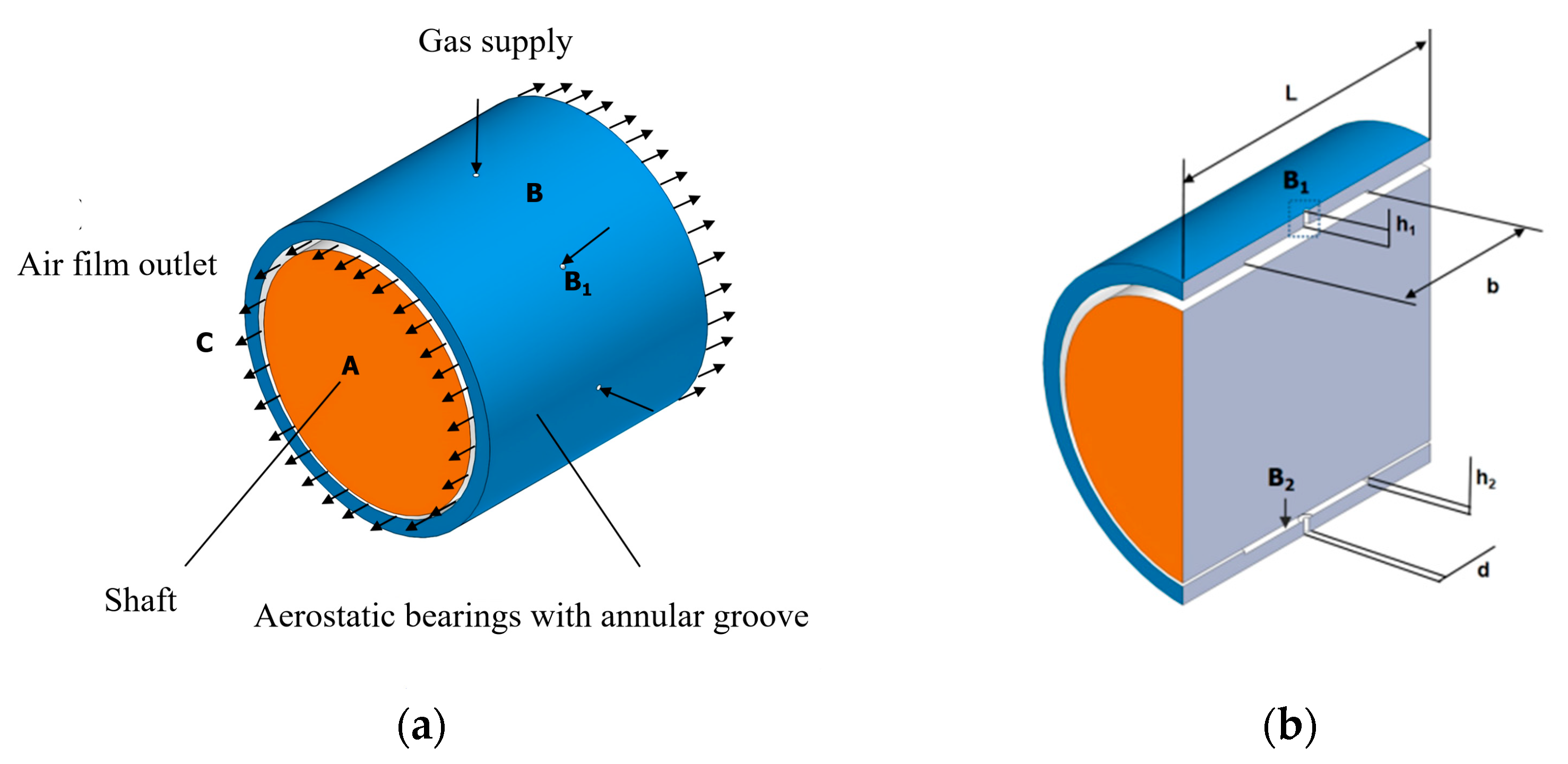
Figure 1 shows the geometric structure of an AGSTAB shaft system. In Figure 1a, A represents the rotor, B denotes the AGSTABs, and C refers the gas film. In Figure 1b,c, B1 represents the throttling holes, B2 indicates the annular groove, L is the bearing length, B is the bearing diameter, e is the eccentricity, d is the diameter of the throttling holes, h1 is the length of the throttling holes, b is the width of the annular groove, and h2 is the depth of the annular groove. Gas enters the throttling holes (B1), flows through the pressure-equalizing chamber, the annular groove (B2), the clearance between bearing and rotor, and finally exits through the outlet holes. As shown in Figure 1d, the boundary conditions for AGSTABs flow field include the inlet, outlet, wall surfaces, and rotating wall surface. Table 1 lists the AGSTAB structural dimensions. To ensure the gas bearing always exhibits orifice throttling without generating annular throttling, the groove depth (h2), orifice diameter (d), and gas film thickness (Ha) must satisfy the condition h2 > d/(4-Ha). Additionally, the throttle length (h1) and diameter (d) must satisfy h1/d < 400 [13]. Table 2 provides the case study parameters. Eccentricity, width ratio, and depth ratio are primary parameters considered in traditional engineering design methods. Generally, when eccentricity is less than 0.5, the stiffness of the gas bearing remains constant. Thus, the eccentricity range for this study was defined as 0.1 to 0.5 [8]. The width and depth ratio were selected based on conventional engineering design range. Width ratio refers to the ratio of groove width to bearing length, whereas depth ratio denotes the ratio of groove depth to throttle length.

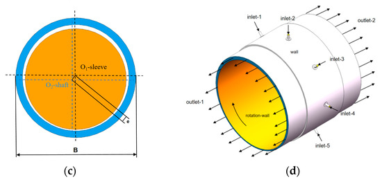
Figure 1.
AGSTAB shaft structure. (a) Assembly structure; (b) axial section; (c) radial section; (d) flow field boundary conditions.

Table 1.
Dimensional parameters of the AGSTAB.
Table 2.
Case parameters.
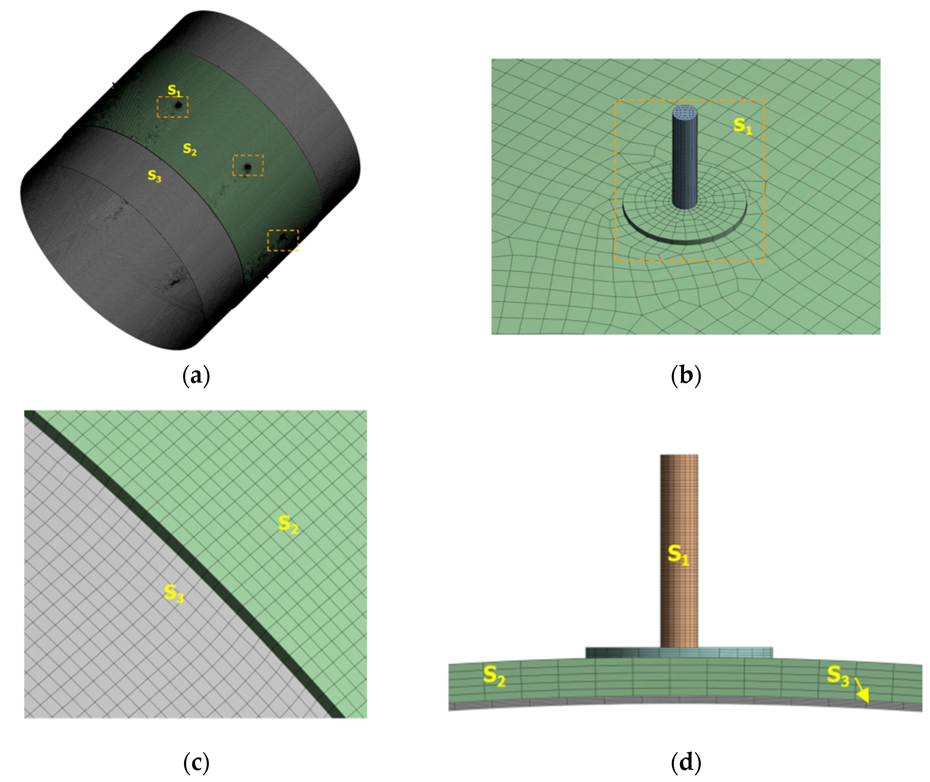
Figure 2 shows the discretization process of AGSTAB flow field geometry. As depicted in Figure 2a, the geometry was divided into three sections using ANSYS DesignModeler: throttling holes and pressure-equalizing chamber (S1), annular groove gas film (S2), and main gas film (S3). All contact surfaces were set as shared nodes. The model was imported into ANSYS Mesh for meshing. Following a mesh independence study, the global mesh size was set to 150 µm. The S1 region was meshed using a multi-zone method, while S2 and S3 regions were meshed using the thin sweeping method. The S1 and S2 regions were further divided into 5 layers along thickness direction. The final mesh contained approximately 1 million elements, with 99.8% of elements achieving an orthogonal quality of 1.
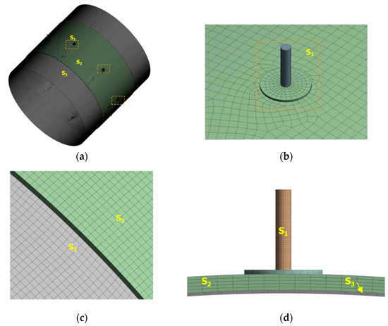
Figure 2.
Flow field discretization. (a) Global grid; (b) co-node; (c) local grids of S2 and S3; (d) local grids of S1, S2, and S3.
2.2. Shear Stress Transport k-ω Model
At high speeds, the flow field of AGSTABs becomes highly complex and turbulent. This is characterized by multi-scale vortices, pronounced velocity fluctuations, and pressure pulsations. Solving such flow fields using direct numerical simulation (DNS) is extremely time-intensive and requires substantial computational resources. The SST k-ω turbulence model offers a more practical solution by applying Reynolds-averaged processing to the Navier–Stokes equations, significantly reducing computational cost. The SST k-ω incorporates additional equations for turbulent kinetic energy (k) and specific dissipation rate (ω), and the model separates turbulent fluctuations, enabling accurate prediction of flow separation and turbulence transition phenomena. The SST k-ω model involves two main components: the Reynolds-averaged equations (including the continuity, momentum, and energy equations) and the k-ω equations. The tensor forms of these equations are as follows:
Equation (1) is continuity equation where is the density of the ideal gas, is time, and u is the time-averaged velocity of the flow field.
Equation (2) is momentum equation where p is the time-averaged pressure of the flow field, is the Reynolds stress term, represents dynamic viscosity, ui uj represent the velocity tensor component along each coordinate axis, and Si is the source term.
Equation (3) is energy equation where s is the gas thermal conductivity, cp is the specific heat capacity, T is the gas temperature, and ST is the viscous dissipation term.
Equations (4) and (5) are the turbulent kinetic energy (k) transport equation and the specific dissipation rate (ω) equation, respectively, where is the turbulent viscosity, Pk and Pω are the production terms for k and ω, Yk Yω are the divergence terms for k and ω respectively; Dω is the cross-diffusion term, are the Prandtl numbers for k and ω.
The SST k-ω turbulence model was solved using SIMPLEC algorithm to obtain AGSTAB pressure distribution. The flow field medium was set as an ideal gas, the supply pressure (PS) was 0.4 MPa, the outlet pressure (Po) was 0 Pa, and the ambient pressure (Pe) was 0 Pa. The rotational wall speed was v; k and ω were discretized using a second-order upwind scheme. During the iterative solution of the algebraic equations, the convergence residuals for continuity, velocity, and energy were all set to 1 × 10⁻⁴. The SST k-ω model combines the advantages of k-ε and k-ω model through a weighted blending function, achieving a smooth transition from near-wall region to free-stream region. This enables more accurate predictions of turbulent separation and shear stress distribution, which is particularly important for complex flow fields, such as those involving high rotational speeds or flow separation. The reliability of SST k-ω model has been validated and discussed in various studies. For instance, in the analysis of hydrodynamic performance of rotating propellers, researchers employed three different turbulence models, showing that the SST k-ω model achieved the best agreement with experimental data [19]. Furthermore, the SST k-ω model was used to simulate the heat transfer characteristics of single-hole impingement jets under both crossflow and non-crossflow conditions. The numerical results closely matched experimental data [20]. Cui et al. built an experimental setup for hydrostatic gas radial bearings to validate the theoretical calculations of static–dynamic characteristics based on the SST k-ω turbulence model. Their results demonstrated that theoretical model was reasonably close to experimental results, with deviations ranging from 5.8% to 10.5%, indicating the model’s capability to accurately compute and analyze static characteristics of gas radial bearings [13]. In conclusion, the selection of SST k-ω model in this study to calculate static–dynamic characteristics of AGSTABs and STABs under high speeds is considered reliable.
3. Results and Discussion
3.1. Analysis of the Mechanism of Dynamic-Static Pressure Effects
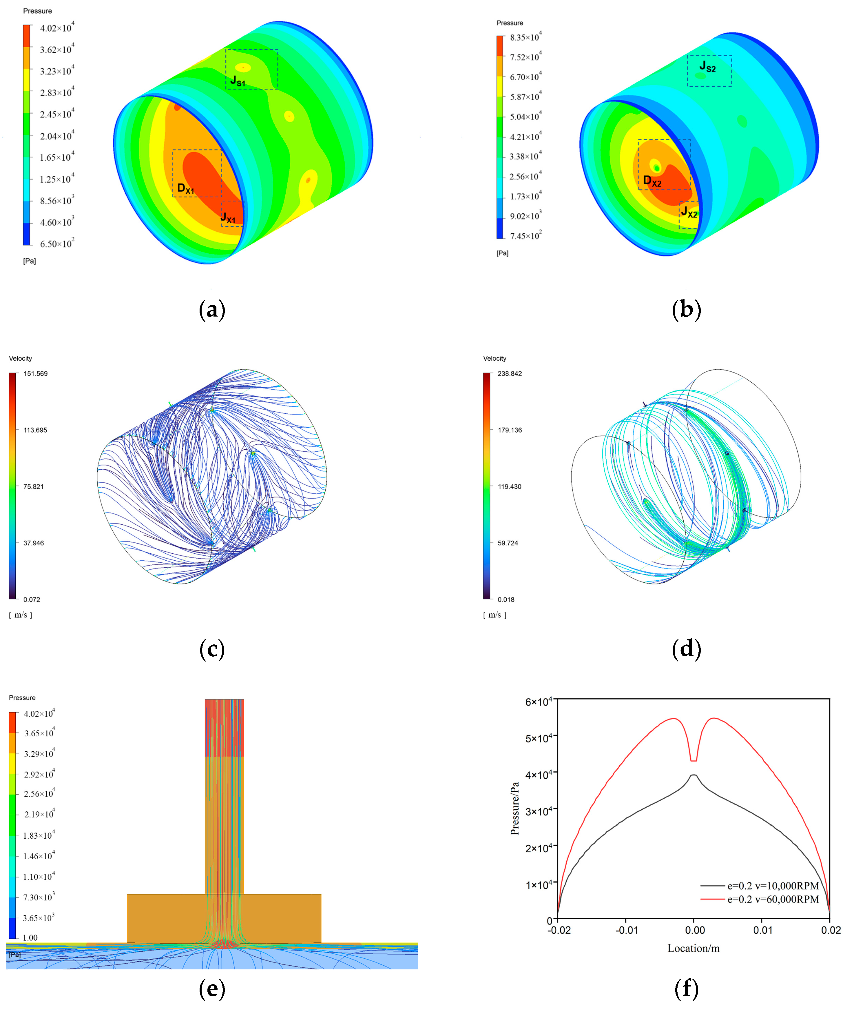
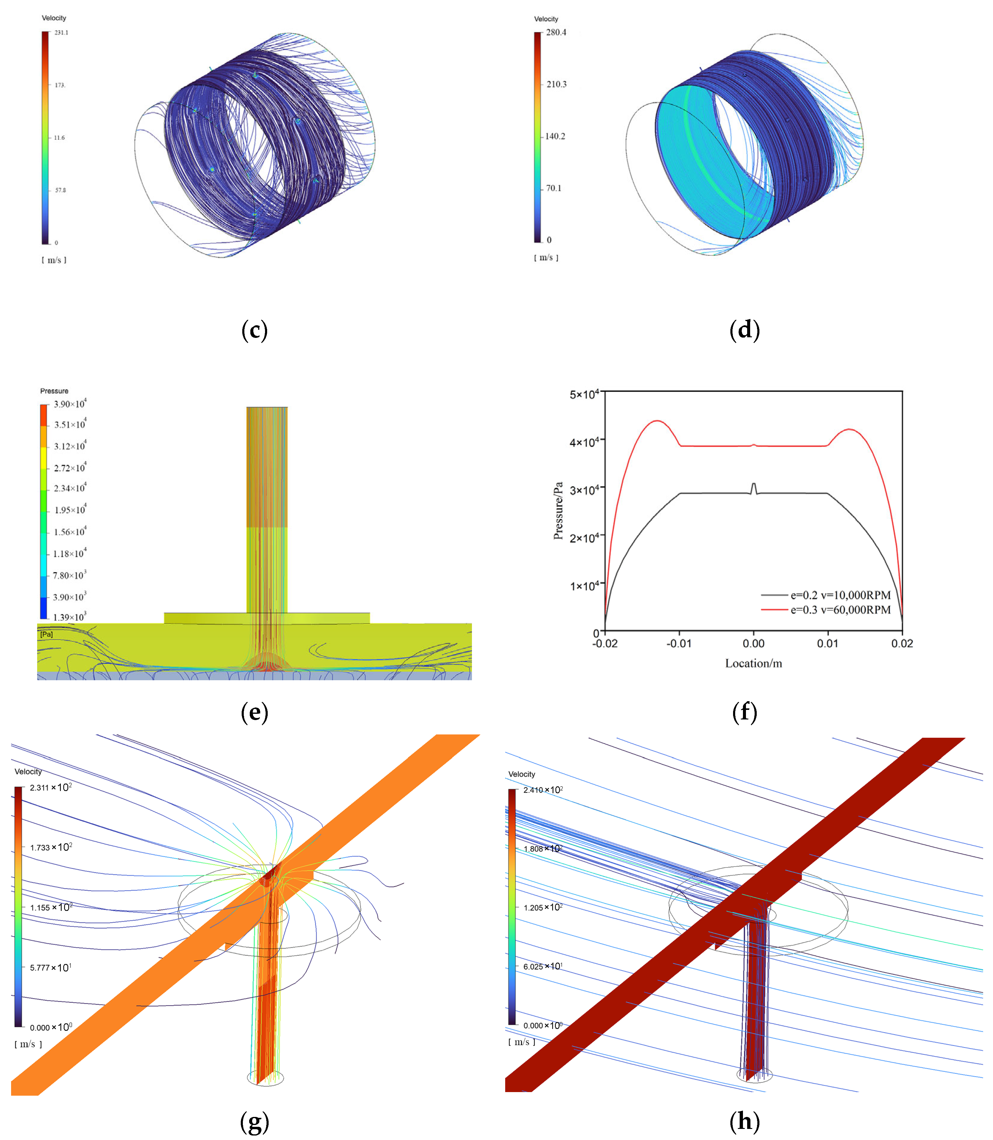
Figure 3 illustrates the pressure distribution of STAB. As shown in Figure 3a,b, the pressure flow field demonstrated a mixed state of static–dynamic pressure effect. Dynamic pressure region was concentrated in the area of minimum gas film thickness, denoted as Dx1 or Dx2, while static pressure region was more widespread, encompassing the gas diffusion areas driven by pressure gradient between supply and outlet boundaries. In Figure 3f, the pressure profile in mixed region of STAB exhibits an A-shaped high-pressure due to static pressure effect of small holes, alongside symmetrical M-shaped high-pressure peaks generated by the dynamic pressure effect. At 60,000 rpm, the A-shaped local high-pressure peak disappeared, while the M-shaped high-pressure peaks increased significantly.

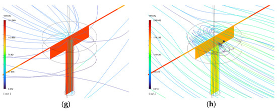
Figure 3.
Flow field characteristics of STABs. (a) Pressure—10,000 RPM; (b) pressure—60,000 RPM; (c) streamlines—10,000 RPM; (d) streamlines—60,000 RPM; (e) orifice throttling effect; (f) axial pressure at Hmin; (g) vortices—10,000 RPM; (h) vortices and backflow—60,000 RPM.
As shown in Figure 3e, due to the throttling effect, the pressurized gas accelerated through the small holes. Upon entering the bearing clearance, it impacted the wall at high speeds due to inertia, causing abrupt changes in velocity and direction, which formed an A-shaped local high-pressure region. Comparing Figure 3c,d, as rotational speed increased, the gas exiting small holes was subjected to strong centrifugal forces, pulling it into rotational flow field. Consequently, at 60,000 rpm, the A-shaped pressure characteristic became less pronounced. The M-shaped pressure resulted from spatial overlap of A-shaped and dynamic pressure effects. The formation of dynamic pressure effects depended on acceleration and gas compression in the wedge-shaped clearance. The combined effects of viscosity, inertia, velocity gradients, and geometry generated dynamic load capacity. A higher-velocity gradient enhanced the dynamic pressure effect. Comparing Figure 3a,b, the dynamic pressure peak in Dx2 region was significantly higher than Dx1, leading to a notable rise of M-shaped pressure shown in Figure 3f.
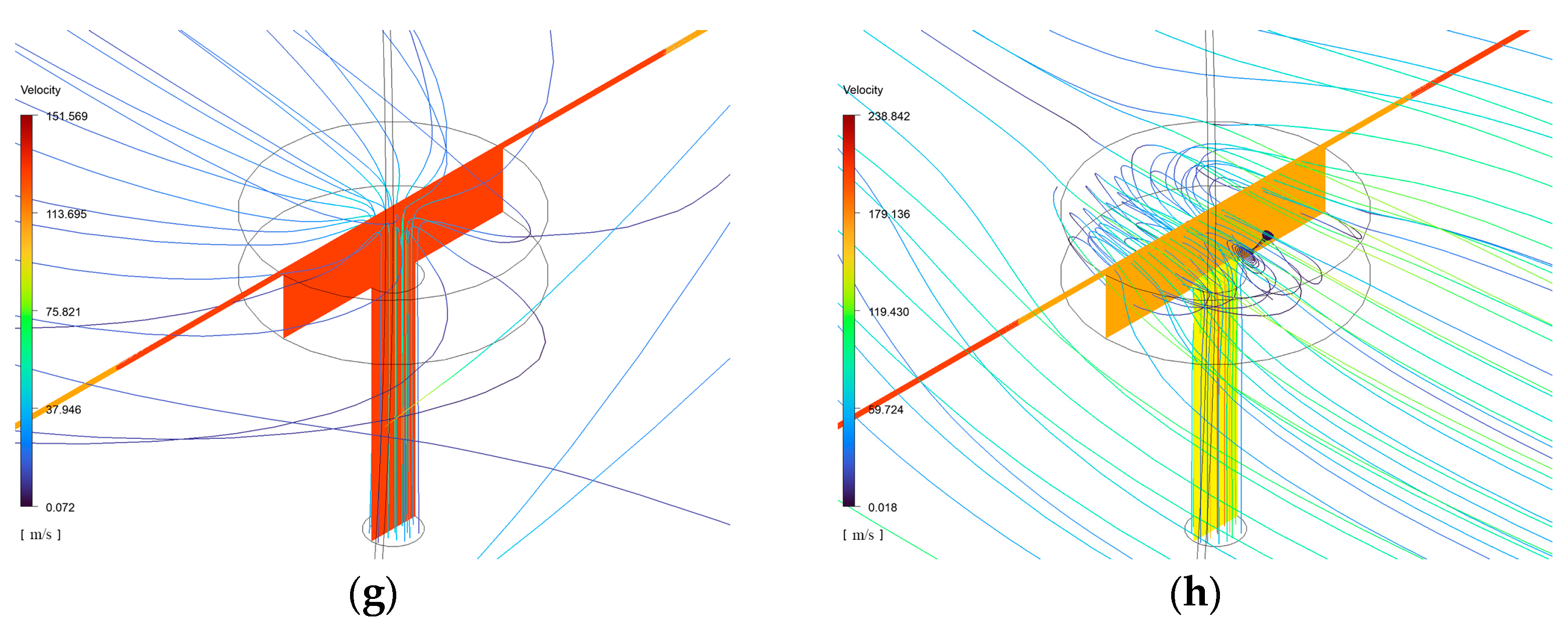
Furthermore, enhancement of dynamic pressure effects intensified the occurrence of vortices and backflow. As shown in Figure 3h, noticeable vortices and backflow were present in Jx2 and Wx regions. As depicted in Figure 3b, the pressure peak in dynamic pressure region reached approximately 60,000 Pa, while the supply pressure in Jx2 region and other throttling holes was 40,000 Pa. This generated a reverse pressure gradient that opposed the rotor’s rotation, causing backflow within the Wx region. The pressure gradient further impacted gas exiting supply holes in Jx2 region, generating vortices and backflow.
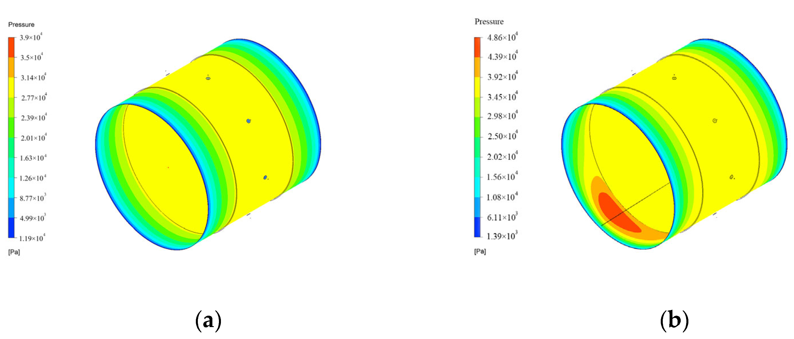
The annular groove structure optimized mixed static–dynamic pressure at high rotational speeds. As shown in Figure 4a,b, the AGSTAB pressure flow field was in a pure static pressure state, exhibiting a broader and more stable pressure distribution within the annular groove. At 60,000 rpm, the flow field transitioned to a mixed state of static and dynamic pressure effects. As depicted in Figure 4f, the pressure profile in the static pressure region of AGSTAB not only exhibited the A-shaped pressure but also featured a flat-line constant-pressure. This indicates that static pressure effect was generated by dual throttling action of small holes and annular groove, resulting in a superior performance for annular groove aerostatic bearing. At 60,000 rpm, A-shaped pressure nearly disappeared, while the flat-line constant pressure increased from 28,000 Pa to 35,000 Pa. The dynamic pressure region formed a narrower, symmetric M-shaped pressure distribution. This shows that higher rotational speeds enhanced annular groove throttling but weakened the effect of small holes.


Figure 4.
Flow field characteristics of AGSTABs. (a) Pressure—10,000 RPM; (b) pressure—60,000 RPM; (c) streamlines—10,000 RPM; (d) streamlines—60,000 RPM; (e) orifice throttling effect; (f) axial pressure at Hmin; (g) vortices—10,000 RPM; (h) vortices and backflow—60,000 RPM.
Comparing Figure 3c and Figure 4c,d, inertial force caused the gas predominantly circulate within annular groove, with only a small portion exiting through the outlet. This led to a secondary throttling effect within annular groove, producing the flat-line constant pressure. The spatial scale in groove thickness direction was much larger than that of the gas film. Therefore, at high speeds, dynamic pressure formation was limited, enabling the annular groove’s throttling effect to fully develop. This increased the secondary throttling effect, leading to a rise in flat-line constant pressure. As shown in Figure 4a,b, in STAB flow field, static–dynamic pressure overlapped, while the annular groove structure separated regions of two effects, minimizing mutual interference. Thus, AGSTAB could effectively suppresses vortex and backflow phenomena.
3.2. Eccentricity
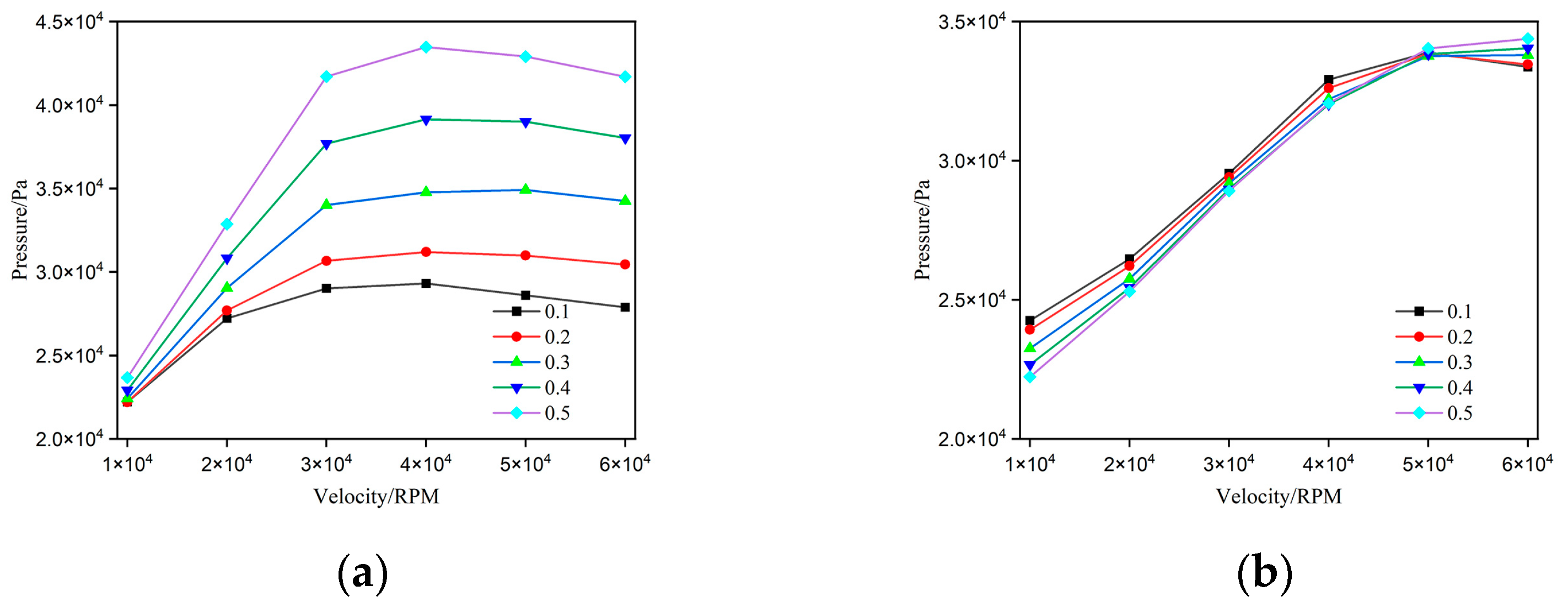
Figure 5 shows the relationship between average load capacity and rotational speed for STABs and AGSTABs. For both bearings, as rotational speed increased from 10,000 to 30,000 rpm, the average load capacity increased significantly across all eccentricity levels, demonstrating that higher rotational speeds enhance load capacity. At the same rotational speed, larger eccentricities caused higher average load capacity. This trend indicates that the greater eccentricity significantly improved gas film performance. For 0.1~0.3 eccentricities, the AGSTAB outperformed STAB, achieving 20% higher average load capacity at 0.1 eccentricity. However, for 0.3~0.5 eccentricities, the traditional STABs surpassed AGSTABs in average load capacity, reaching its maximum at 0.5 eccentricity. While average load capacity of STABs plateaued at 30,000 rpm, the AGSTABs continued to show increasing with rising speeds. This clearly demonstrates that annular groove structure effectively raised the stability threshold for high-speed aerostatic bearings. Furthermore, the results of Figure 5 are consistent with theoretical trends presented in Reference [8], which enhances the reliability of simulation results.
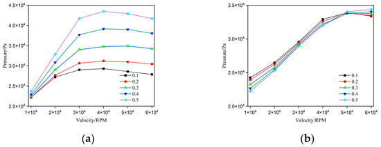
Figure 5.
Average gas film load capacity of gas bearings under different eccentricity conditions. (a) STABs; (b) AGSTABs.
The load capacity decrease in Figure 5 was mainly due to gas compressibility. The results from Figure 3 and Figure 4 indicate that flow fields of bearings exhibited static and dynamic pressure effects, with a higher proportion of the latter. Typically, the load capacity generated by dynamic pressure is proportional to bearing’s compressibility number. An increase in velocity or gas viscosity usually leads to a higher compressibility number. However, when gas compressibility is considered and rotational speed exceeds a certain threshold, the compressibility number is no longer influenced by factors such as velocity, gas viscosity, or bearing clearance. At this point, the load capacity of flow field depends solely on gas density. Therefore, in STABs, velocities exceeding 30,000 rpm lead to the average load capacity.
Figure 6 shows pressure distribution at the thinnest gas film position in STABs and AGSTABs under different eccentricities. Comparing Figure 6a,d, the flow fields of both gas bearings were dominated by static pressure effects under eccentricities from 0.1 to 0.3. The M-shaped dynamic pressure increased for STABs under eccentricities from 0.4 to 0.5. Meanwhile, the AGSTAB remained in a pure static pressure state, showing both A-shaped high-pressure and flat-line constant pressure. Comparing Figure 6b,e, as the eccentricity increased from 0.1 to 0.5, the M-shaped dynamic pressure rose sharply for STABs. In contrast, the AGSTABs remained in a static pressure state under eccentricities from 0.1 to 0.2. The flow field transitioned to a mixed state-dynamic pressure effects, with the narrow M-shaped dynamic pressure peak increasing from 3 MPa to 4.8 MPa, under 0.2 to 0.5 eccentricities. Figure 6c,e show trends similar to Figure 6b,e. In summary, for both bearings, increasing eccentricity enhanced the dynamic pressure effects. For same eccentricity, AGSTABs required higher rotational speeds to generate dynamic pressure.
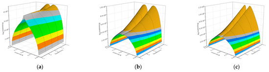
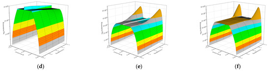
Figure 6.
Pressure at minimum gas film thickness under different eccentricity. (a) 10,000 RPM STABs; (b) 30,000 RPM STABs; (c) 60,000 RPM STABs; (d) 10,000 RPM AGSTABs; (e) 30,000 RPM AGSTABs; (f) 60,000 RPM AGSTABs.
3.3. Width Ratio
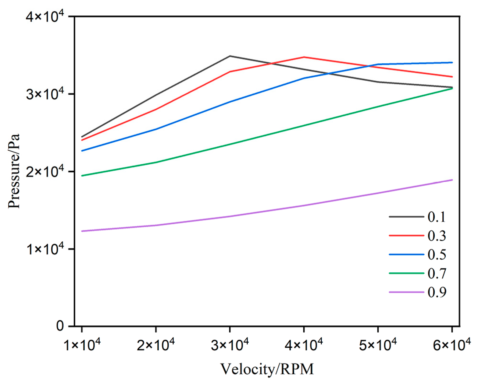
Figure 7 illustrates the variation of average load capacity with rotational speed for AGSTABs. For all width ratio conditions, the average load capacity increased significantly as rotational speed rose from 10,000 to 40,000 rpm. However, beyond 40,000 rpm, the load capacity for certain width ratios (0.1, 0.3, 0.5) started to decline. At the same speed, low width ratios (0.1 and 0.3) significantly increased load capacity, whereas higher ratios (0.7 and 0.9) brought only slight improvements. This indicates that narrower grooves were more effective at concentrating pressure, thereby substantially enhancing load capacity. As width ratio increased, average load capacity also rose. For bearings with width ratios of 0.1, 0.3, and 0.5, the average load capacity reached its peak at rotational speeds of 30,000 rpm, 40,000 rpm, and 60,000 rpm, respectively. These findings suggest that the design of AGSTABs should account for operational speed range and width ratio for achieving optimal load capacity performance.

Figure 7.
Average gas film load capacity of AGSTABs under different width ratios.
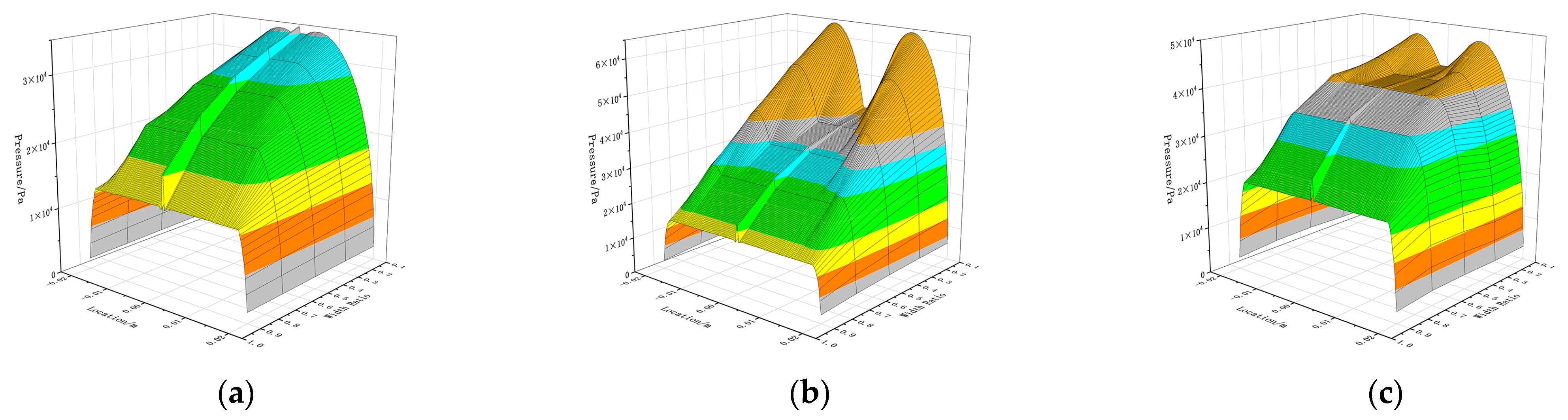
Figure 8 depicts pressure variation at the thinnest point of gas film with different width ratios. In Figure 8a, as width ratio increases from 0.1 to 0.9, the A-shaped pressure decreases from 3.5 MPa to 1.5 MPa, and the flat-line constant pressure drops from 3.3 MPa to 1.4 MPa. During this range, the flow field is predominantly governed by static pressure effects. As shown in Figure 8b, as width ratio varied from 0.1 to 0.9, the flow field transitioned into a mixed state of static–dynamic pressure effect. A-shaped pressure decreased from 3.8 MPa to 1.7 MPa, flat-line constant pressure dropped from 3.5 MPa to 1.6 MPa, and narrow M-shaped dynamic pressure peak declined from 6.3 MPa to 1.7 MPa. In Figure 8c, the trends closely align with those observed in Figure 8b.

Figure 8.
Pressure distribution curves at the minimum gas film thickness position of aerostatic bearings under different width ratios. (a) 10,000 RPM AGSTABs; (b) 30,000 RPM AGSTABs; (c) 60,000 RPM AGSTABs.
In conclusion, width ratio significantly influences the relative contributions of static and dynamic pressure effects to overall load capacity. As width ratio increases, the contribution of dynamic and static pressure effects gradually decrease. Higher width ratios result in a greater reliance on static pressure effects for load capacity.
3.4. Depth Ratio
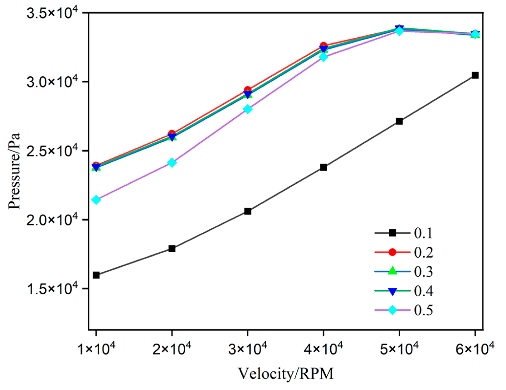
Figure 9 shows the relationship between average load capacity and rotational speed for AGSTABs. Overall, as rotational speed increased from 10,000 rpm to 60,000 rpm, the average load capacity exhibited a significant upward trend. From 10,000 to 30,000 rpm, the load capacity increased significantly with depth ratio, particularly within the range from 0.1 to 0.4, achieving improvement of more than 60%. However, from 40,000 to 60,000 rpm, the load capacity differences across various depth ratios gradually diminished. This trend was especially evident for the 0.2 depth ratio, where the load capacity variations became minimal. These results indicate that the influence of annular groove depth on load capacity weakens at high speed.

Figure 9.
Average gas film load capacity of AGSTABs under different depth ratios.
Figure 10 depicts the pressure variation at the thinnest gas film location for AGSTABs. As shown in Figure 10a, the flow field remained in a pure static pressure state across all rotational speed ranges. At 10,000 rpm, as depth ratio increased from 0.1 to 0.2, the flat-line constant pressure rose from 1.8 MPa to 2.7 MPa. When depth ratio increased further from 0.2 to 0.4, the flat-line constant pressure continued to rise from 2.7 MPa to 2.8 MPa, though the overall change was minimal. The trends observed in Figure 10b,c are consistent with this pattern.
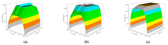
Figure 10.
Pressure curves at the minimum gas film thickness position of aerostatic bearings under different depth ratios. (a) 10,000 RPM AGSTABs; (b) 30,000 RPM AGSTABs; (c) 60,000 RPM AGSTABs.
In summary, selecting an appropriate depth ratio can enhance the static pressure effects without amplifying the generation of dynamic pressure effects.
4. Conclusions
This study leverages the SST k-ω model, combined with ANSYS Fluent, to compare static–dynamic pressure effect of AGSTABs and STABs at 10,000~60,000 rpm. The effects of eccentricity, width ratio, and depth ratio were analyzed, leading to the following conclusions.
STABs combine static and dynamic pressure effects at high speeds, while AGSTABs decouple them to enhance load capacity, effectively reducing vortex and backflow intensity. At 60,000 rpm, STABs’ dynamic and static pressure peaks are 6 MPa and 4 MPa, respectively, causing circumferential pressure differences and backflow. AGSTABs shift the static–dynamic pressure distribution from circumferential to axial, preventing backflow, with static and dynamic pressure peaks of 3.5 MPa and 4.5 MPa.
Increasing eccentricity enhances load capacity for both bearings. At 0.1~0.3 eccentricities, AGSTABs outperform STABs, achieving 20% higher capacity. As eccentricity reaches 0.5, STABs exhibit a sharp rise in M-shaped dynamic pressure, while AGSTABs shift from static pressure dominance to a mixed state, with peaks increasing from 3 MPa to 4.8 MPa.
The width ratio affects the contributions of static and dynamic pressure to load capacity. As width ratio increases, dynamic pressure declines, while the static pressure from small-hole and annular groove throttling weaken. With a width ratio increase from 0.1 to 0.9, the flow field transitions to mixed static–dynamic pressure state, with static pressure dropping from 3.5 MPa to 1.6 MPa and dynamic pressure peaks narrowing from 6.3 MPa to 1.7 MPa.
The depth ratio exhibits minimal influence on dynamic pressure performance but enhances the static pressure effect, leading to a slight improvement of AGSTABs’ load capacity. At 10,000 rpm, increasing depth ratio from 0.1 to 0.2 significantly raises the static pressure from 1.8 MPa to 2.7 MPa. Further increasing the ratio to 0.4 leads to a slight rise from 2.7 MPa to 2.8 MPa, indicating a relatively small overall variation.
This study clarifies the advantages of annular groove structures in coupling static and dynamic pressures effects, reducing vortex and backflow intensity, and enhancing load capacity by investigating the high-speed flow field characteristics of AGSTABs. The findings provide theoretical and numerical analysis for annular groove and other composite throttling high-speed gas bearings. These insights have the potential to overcome limitations of load capacity and stiffness. They also improve the adaptability of high-speed spindles to transient conditions. Additionally, they ensure stable operation under high rotational speeds, frequent start–stop cycles, and sudden changes in working conditions. This lays a solid foundation for further advancements in equipment manufacturing and precision instrumentation.
Author Contributions
Methodology, W.S.; software, W.S.; validation, W.S., P.C. and M.L.; formal analysis, W.S.; investigation, W.S. and D.W.; writing—original draft preparation, W.S.; supervision, C.S.; project administration, J.Z.; funding acquisition, C.S. All authors have read and agreed to the published version of the manuscript.
Funding
This research was funded by National Key Research and Development Plan: Research and Application Demonstration of the Key Technical System for National Quality Infrastructure in the High-Speed Precision Sliding Bearing Industry, grant number 2021YFF0603000.
Data Availability Statement
The original data presented in the study are available from the corresponding author upon reasonable request.
Acknowledgments
The authors thank the China Productivity Center for Machinery for their financial support and would like to thank the editors and anonymous reviewers for their valuable comments and suggestions.
Conflicts of Interest
Minggui Li was employed by the company China Xinshidai Certification Body. The remaining authors declare that the research was conducted in the absence of any commercial or financial relationships that could be construed as a potential conflict of interest.
References
- Rowe, W.B. Hydrostatic and hybrid bearing design. Tribol. Int. 1983, 17, 353. [Google Scholar] [CrossRef]
- Colombo, F.; Lentini, L.; Raparelli, T.; Trivella, A. Special Issue “Gas Bearings: Modelling, Design and Applications”. Appl. Sci. 2022, 12, 9048. [Google Scholar] [CrossRef]
- Belforte, G.; Colombo, F.; Raparelli, T.; Trivella, A.; Viktorov, V. Comparison between grooved and plane aerostatic thrust bearings: Static performance. Meccanica 2011, 46, 547–555. [Google Scholar] [CrossRef]
- Chen, X.; Mills, J.K.; Shi, K.; Bao, G. Numerical investigation on the static performance of aerostatic journal bearings with different pocket shapes by the finite-element method. Proc. Inst. Mech. Eng. Part J J. Eng. Tribol. 2021, 235, 1897–1911. [Google Scholar] [CrossRef]
- Li, P.; Li, J.; Shi, Z.; Zhang, H.; Xiao, S.; Li, X.; Gu, F. Effects of manufacturing errors and micro-groove surfaces on the static and dynamic characteristics of water-lubricated bearings. Phys. Scr. 2023, 98, 95903. [Google Scholar] [CrossRef]
- Stanev, P.T.; Wardle, F.; Corbett, J. Investigation of grooved hybrid air bearing performance. Proc. Inst. Mech. Eng. Part K J. Multi-Body Dyn. 2004, 218, 95–106. [Google Scholar] [CrossRef]
- Su, C.T.; Lie, K.N. Rotation effects on hybrid hydrostatic/hydrodynamic journal bearings. Ind. Lubr. Tribol. 2001, 53, 261–269. [Google Scholar] [CrossRef]
- Powell, J.W. Design of Aerostatic Bearings; The Machinery Publishing CO: Brighton, UK, 1970. [Google Scholar]
- Yao, S. Gas Thrust Bearing Technology Based on the Principle of Hybrid Lubrication; Harbin Institute of Technology: Harbin, China, 2006. [Google Scholar]
- Yu, X.; Shi, G.; Jiang, H.; Dai, R.; Jia, W.; Yang, X.; Gao, W. Effect of texture parameters on the lubrication performance of static and dynamic pressure thrust bearings and multi-objective optimization. Ind. Lubr. Tribol. 2024, 76, 526–536. [Google Scholar] [CrossRef]
- Gao, S.; Shi, Y.; Xu, L.; Chen, H.; Cheng, K. Investigation on influences of herringbone grooves for the aerostatic journal bearings applied to ultra-high-speed spindles. Proc. Inst. Mech. Eng. Part C J. Mech. Eng. Sci. 2019, 233, 5795–5812. [Google Scholar] [CrossRef]
- Schlums, H.; Hühne, C.; Sinapius, M. Design of a Herringbone-Grooved Bearing for Application in an Electrically Driven Air Compressor. Machines 2022, 10, 662. [Google Scholar] [CrossRef]
- Cui, W.; Li, S.; Zhu, B.; Yang, F.; Chen, B. Research on the influence of a micro-groove-orifice structure and its layout form on the static characteristics of aerostatic journal bearings under a high gas supply pressure. Adv. Mech. Eng. 2023, 15, 1–18. [Google Scholar] [CrossRef]
- Yu, X.; Feng, Y.; Jiang, H.; Gao, W.; Shi, G.; Dai, R.; Jia, W.; Wang, J.; Jiao, J. Investigation on the Dynamic Pressure Effect of Clearance Oil Film at a Stepped Hydrostatic Thrust Bearing Working in Heavy Loading Duty. Tribol. Trans. 2024, 67, 173–184. [Google Scholar] [CrossRef]
- Ke, C.; Qiu, S.; Li, K.; Xiong, L.; Peng, N.; Zhang, X.; Dong, B.; Liu, L. Numerical Computation and Experimental Research for Dynamic Properties of Ultra-High-Speed Rotor System Supported by Helium Hydrostatic Gas Bearings. Lubricants 2024, 12, 302. [Google Scholar] [CrossRef]
- Guo, M.; Tian, Z.; Rong, Z.Y. CFD-based method for hydrostatic bearings performance: Static characteristics with various recess shapes. Int. J. Hydromechatronics 2024, 7, 176–192. [Google Scholar] [CrossRef]
- Hariharan, G.; Kumar, S.; Kumar, N. Enhancing performance in water lubricated bearings with groove structures: A CFD analysis. Cogent Eng. 2024, 11, 2399762. [Google Scholar] [CrossRef]
- Wang, Y.; Jacobs, G.; Zhang, S.; Klinghart, B.; König, F. Lubrication mechanism analysis of textures in journal bearings using CFD simulations. Ind. Lubr. Tribol. 2024. [Google Scholar] [CrossRef]
- Sun, C.; Zhao, J. Hydrodynamic Performance Analysis of Contra-Rotating Propellers Based on CFD. Ship Sci. Technol. 2019, 41, 36–40. [Google Scholar]
- Liu, A.; Wang, Y.; Hao, C. Reliability of the SST k-ω Model in Impinging Jet Cooling. J. Nanchang Hangkong Univ. Nat. Sci. Ed. 2009, 23, 5. [Google Scholar]


Disclaimer/Publisher’s Note: The statements, opinions and data contained in all publications are solely those of the individual author(s) and contributor(s) and not of MDPI and/or the editor(s). MDPI and/or the editor(s) disclaim responsibility for any injury to people or property resulting from any ideas, methods, instructions or products referred to in the content. |
© 2025 by the authors. Licensee MDPI, Basel, Switzerland. This article is an open access article distributed under the terms and conditions of the Creative Commons Attribution (CC BY) license (https://creativecommons.org/licenses/by/4.0/).