Influence of Circumferential Convergent Wedge Pocket on the Segmented Annular Seal’s Static and Dynamic Characteristics


Abstract
1. Introduction
2. Design of Seal Structure with Circumferential Convergent Wedge Pockets
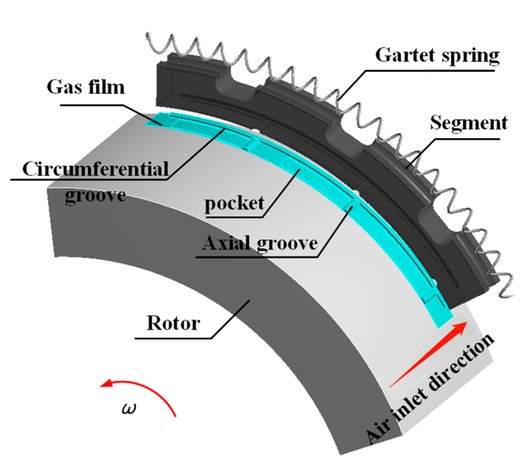
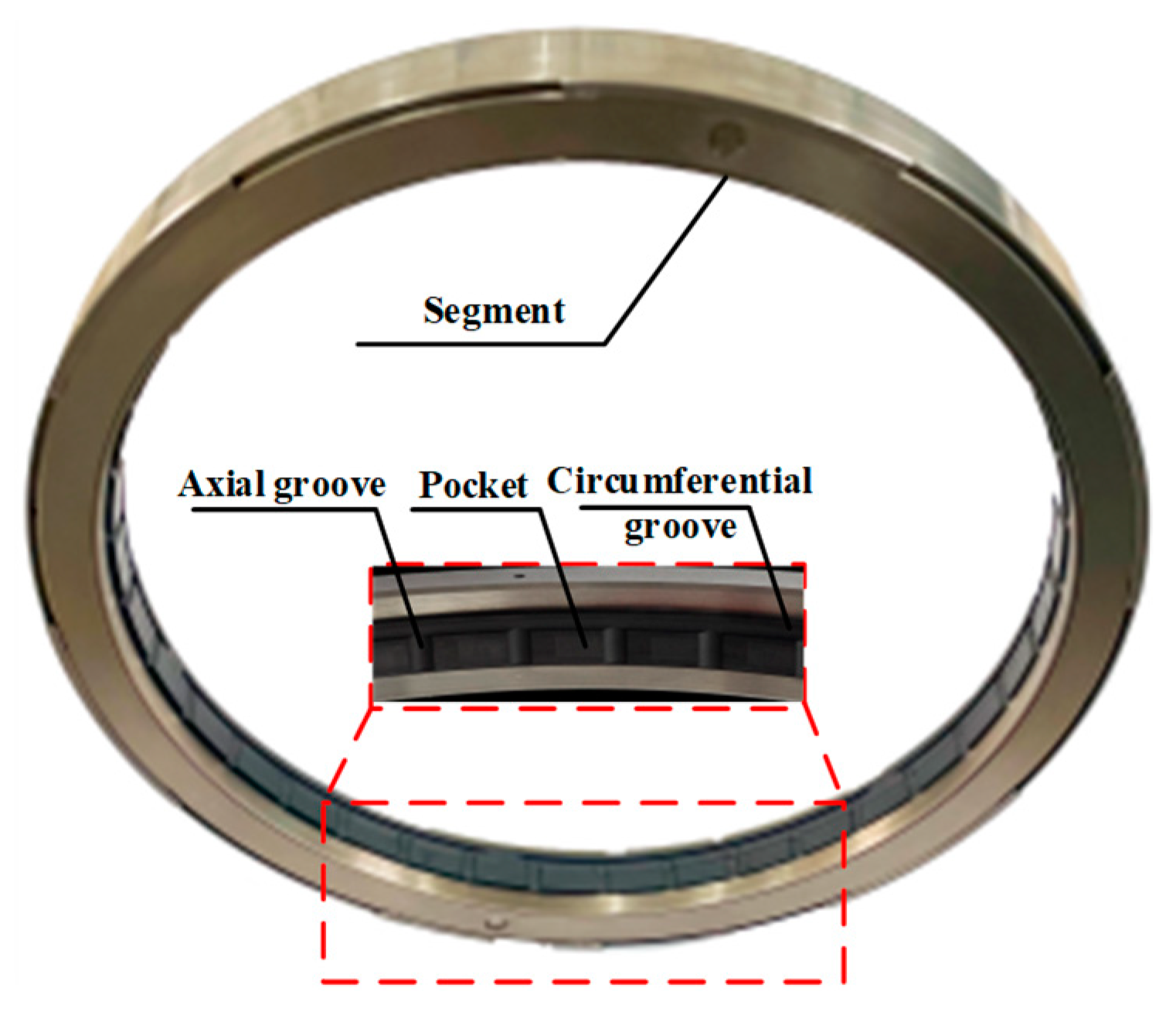
2.1. Configuration of the Segmented Annular Seal
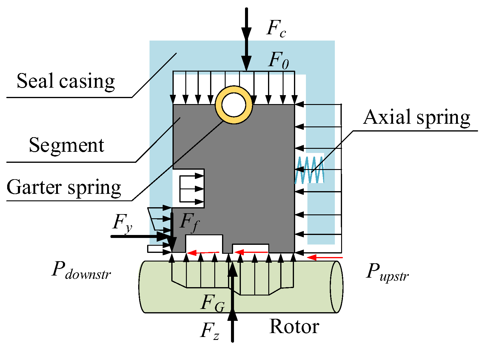
2.2. Working Principle
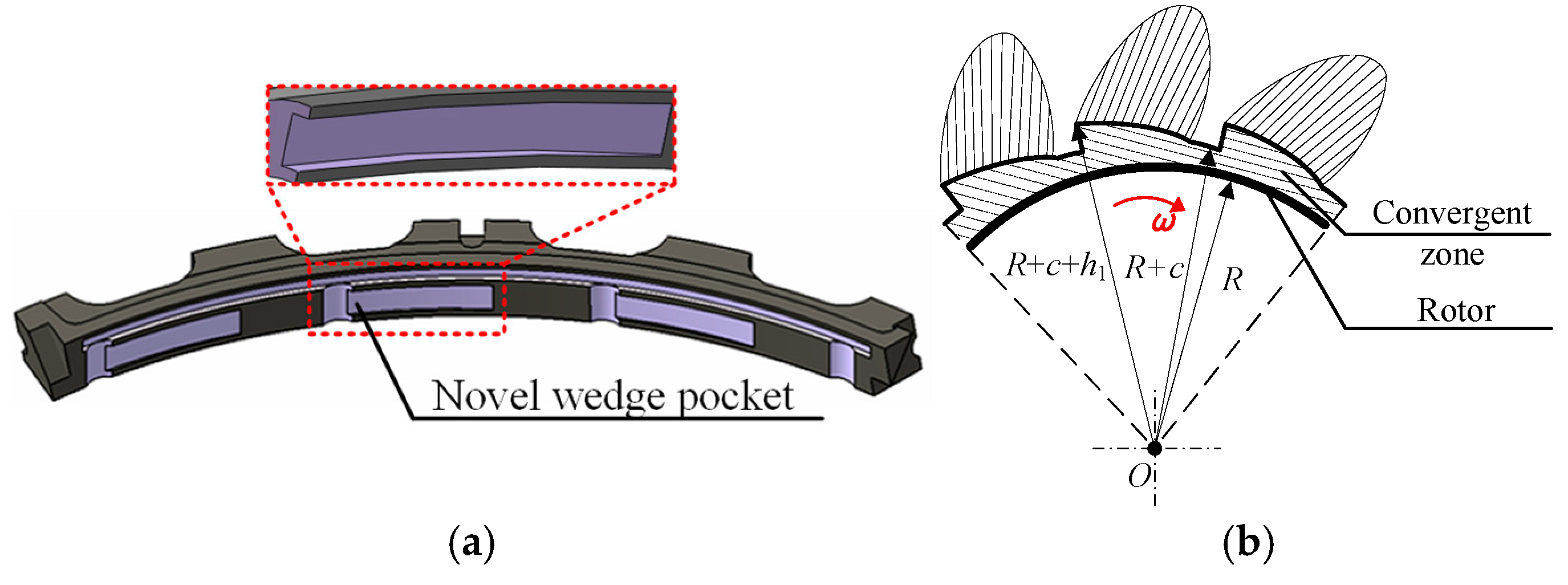
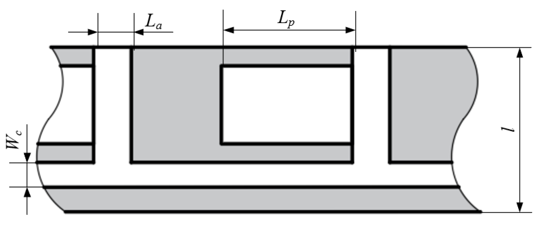
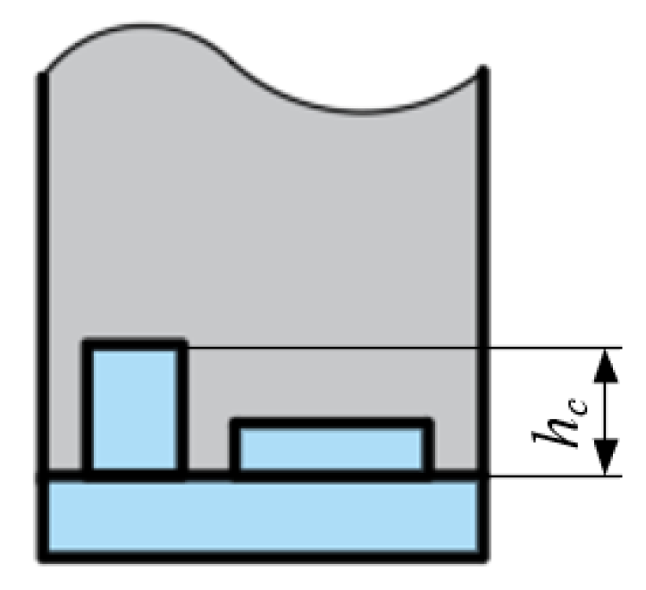
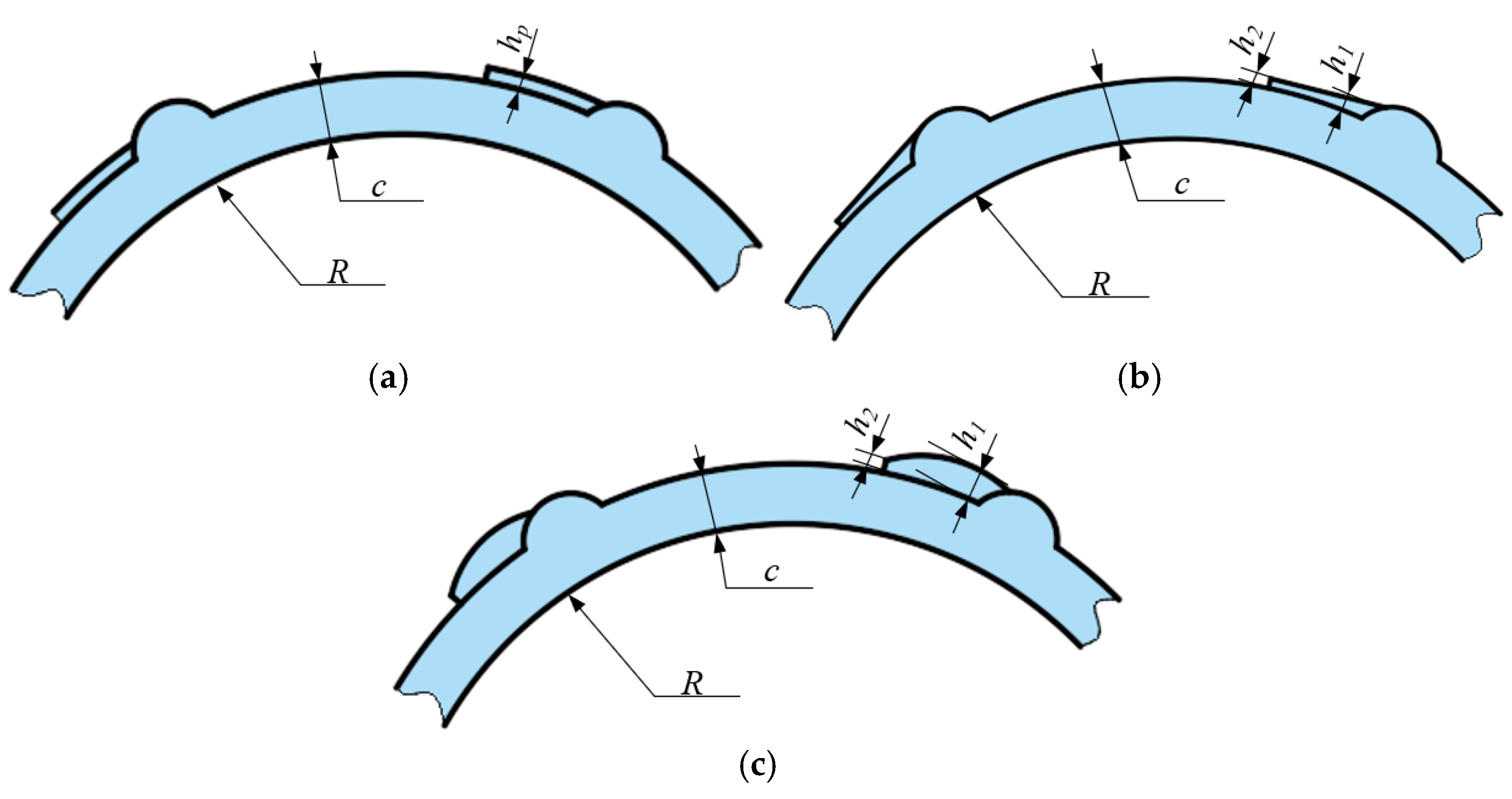
2.3. Design of Seal with Circumferential Convergent Wedge Pocket
3. Theoretical Model
3.1. Theoretical Model of Static and Dynamic Characteristics
3.1.1. Static Characteristics
3.1.2. Dynamic Characteristics
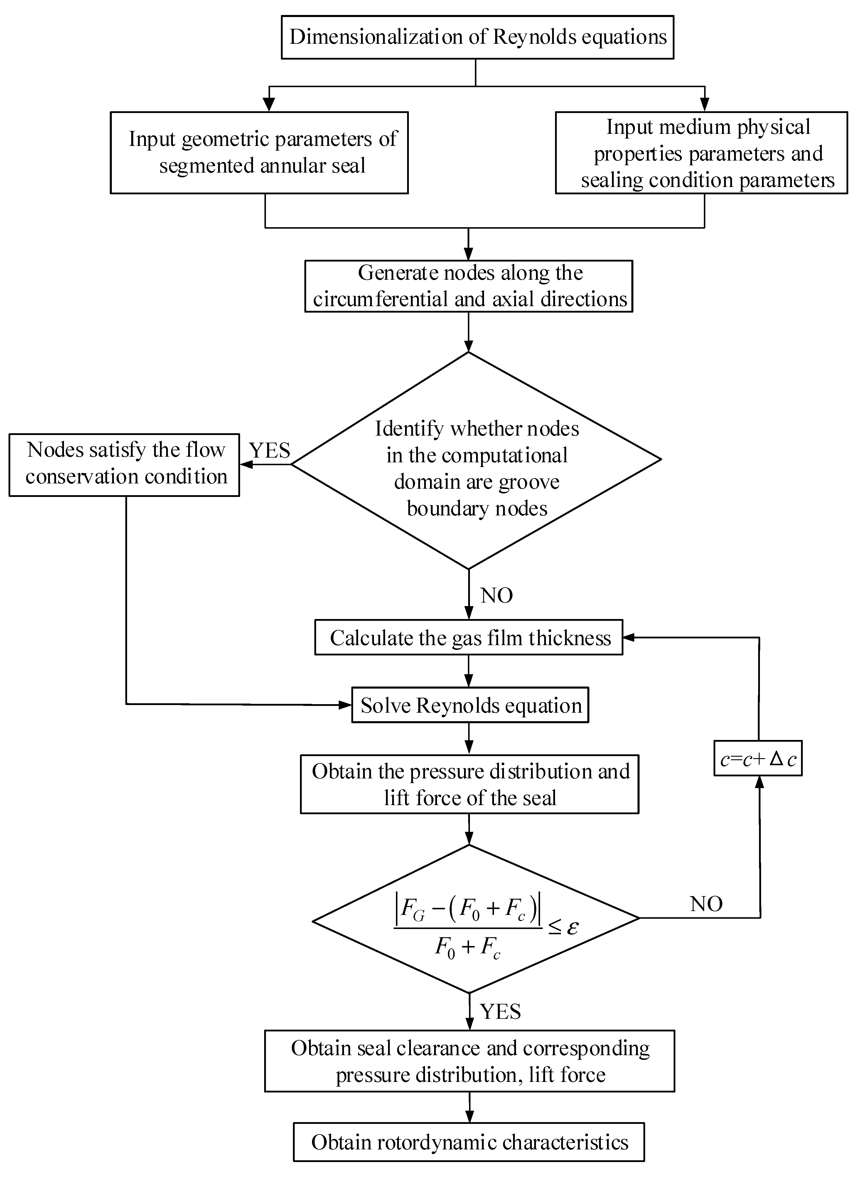
3.2. Static and Dynamic Characteristics Solution
4. Analysis Model and Accuracy Verification of Computational Method
4.1. Geometric Configuration and Working Conditions
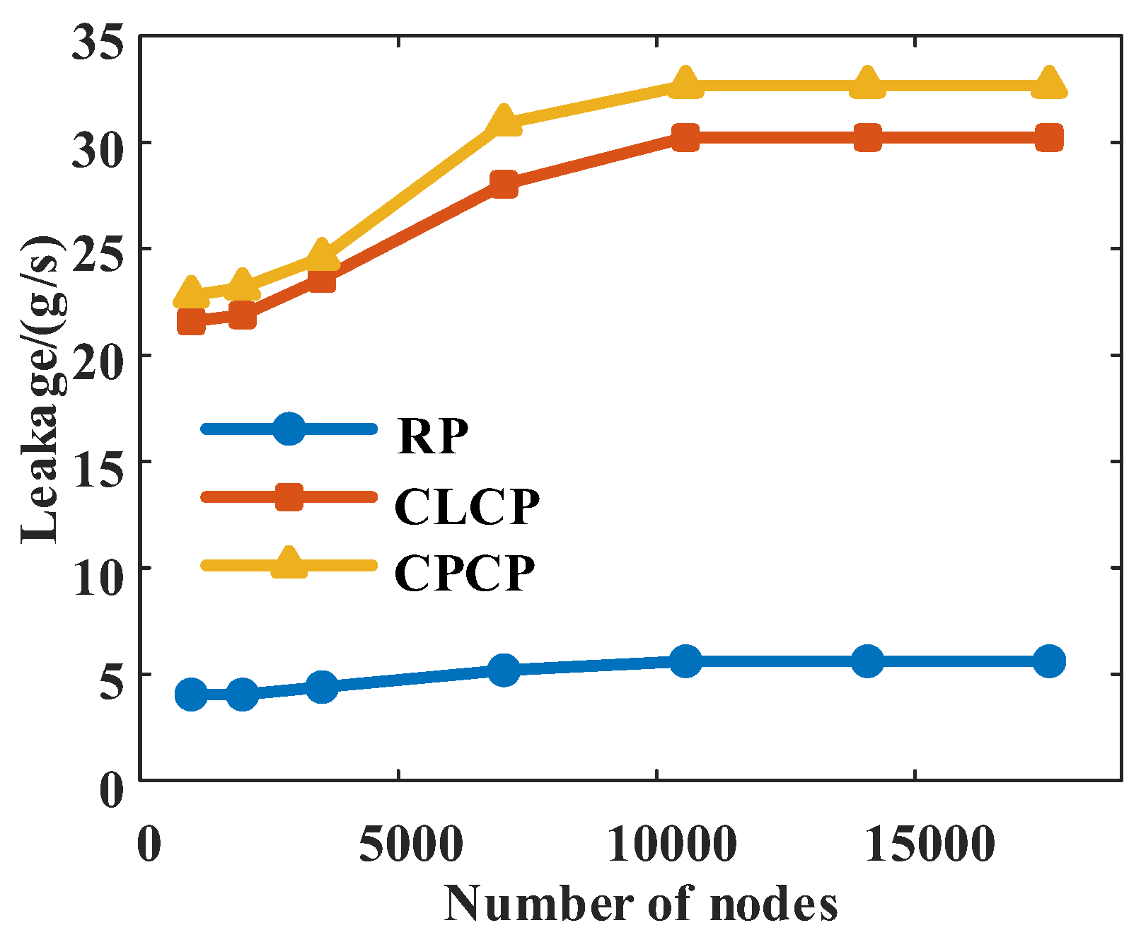
4.2. Influence of Node Density on Results
4.3. Calculation Method Accuracy Verification
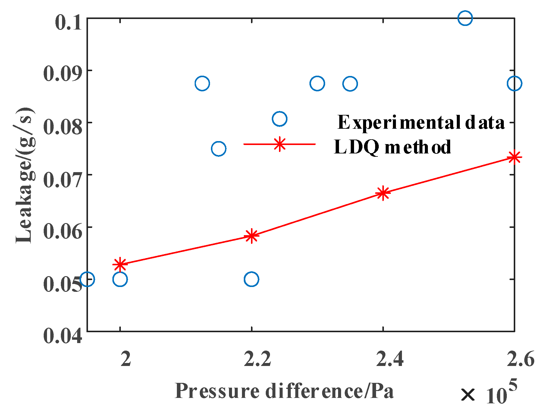
4.3.1. Experimental Validation of Leakage Characteristics’ Calculation Methods
4.3.2. Accuracy Verification of Dynamic Characteristic Solution Method
5. Results and Discussion
5.1. Static Characteristics Results
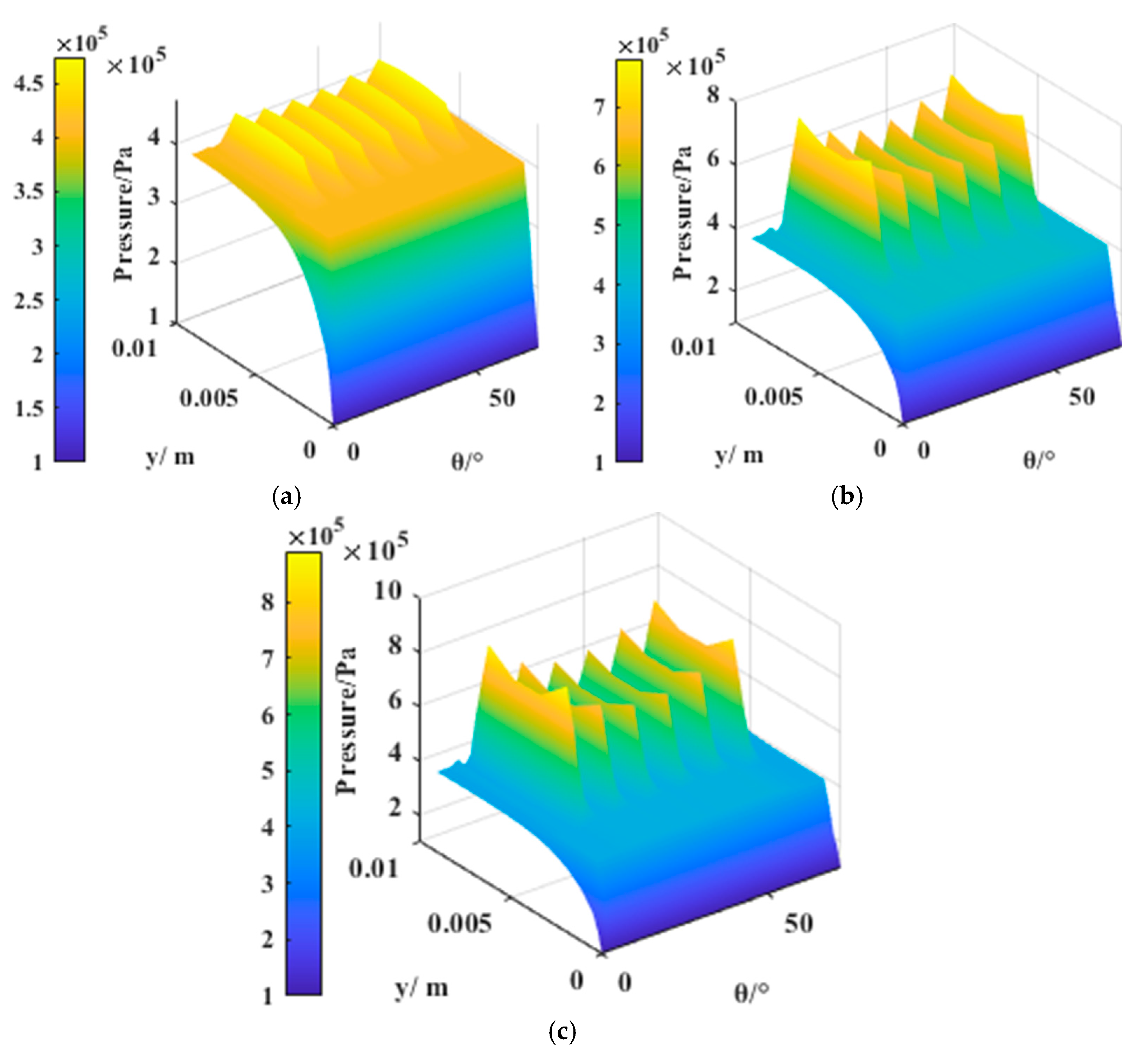
5.1.1. Distribution of Pressure
5.1.2. Leakage
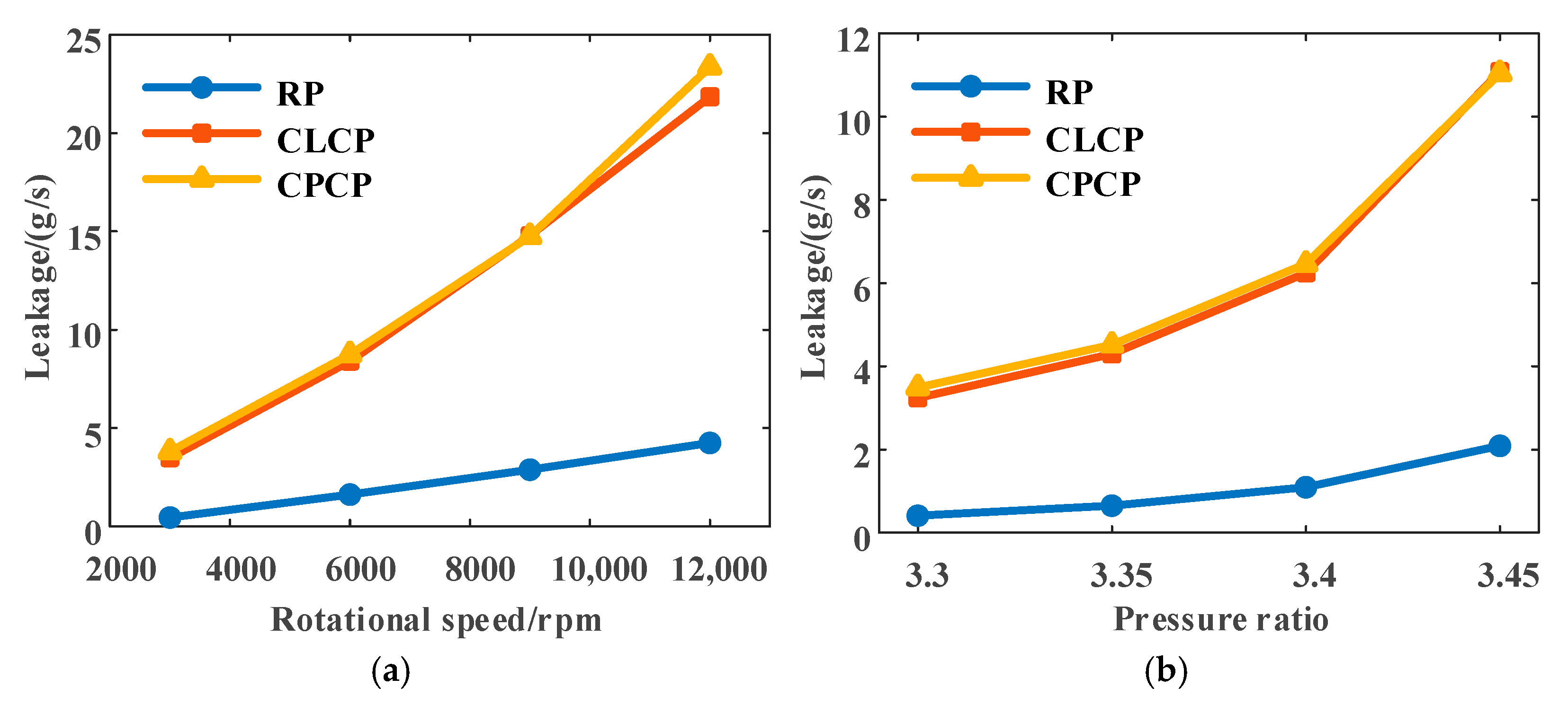
Influence of Operating Parameters on Leakage
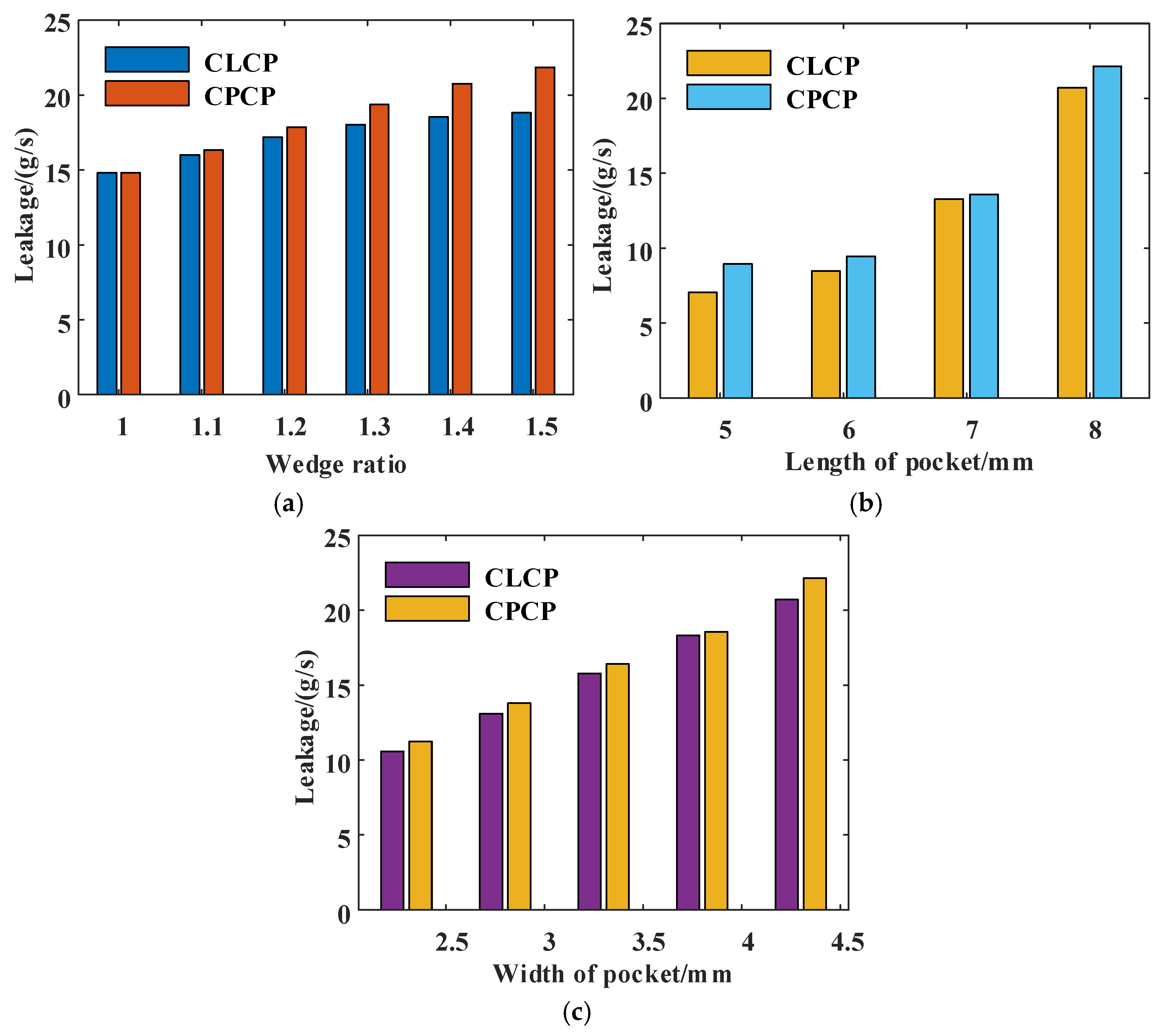
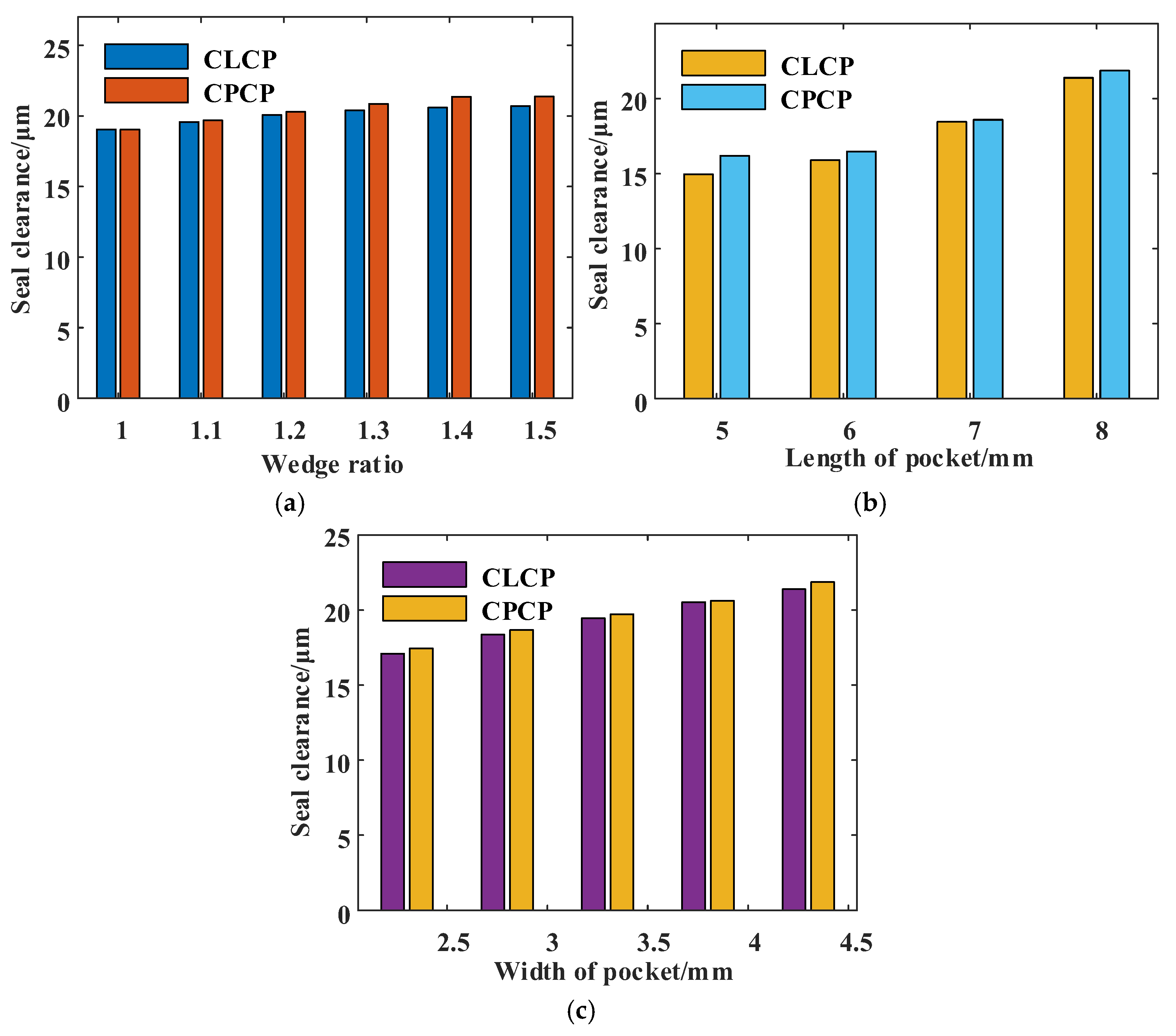
Influence of Structural Parameters on Leakage
5.2. Dynamic Characteristics Results
5.2.1. Influence of Operating Parameters on Dynamic Characteristics
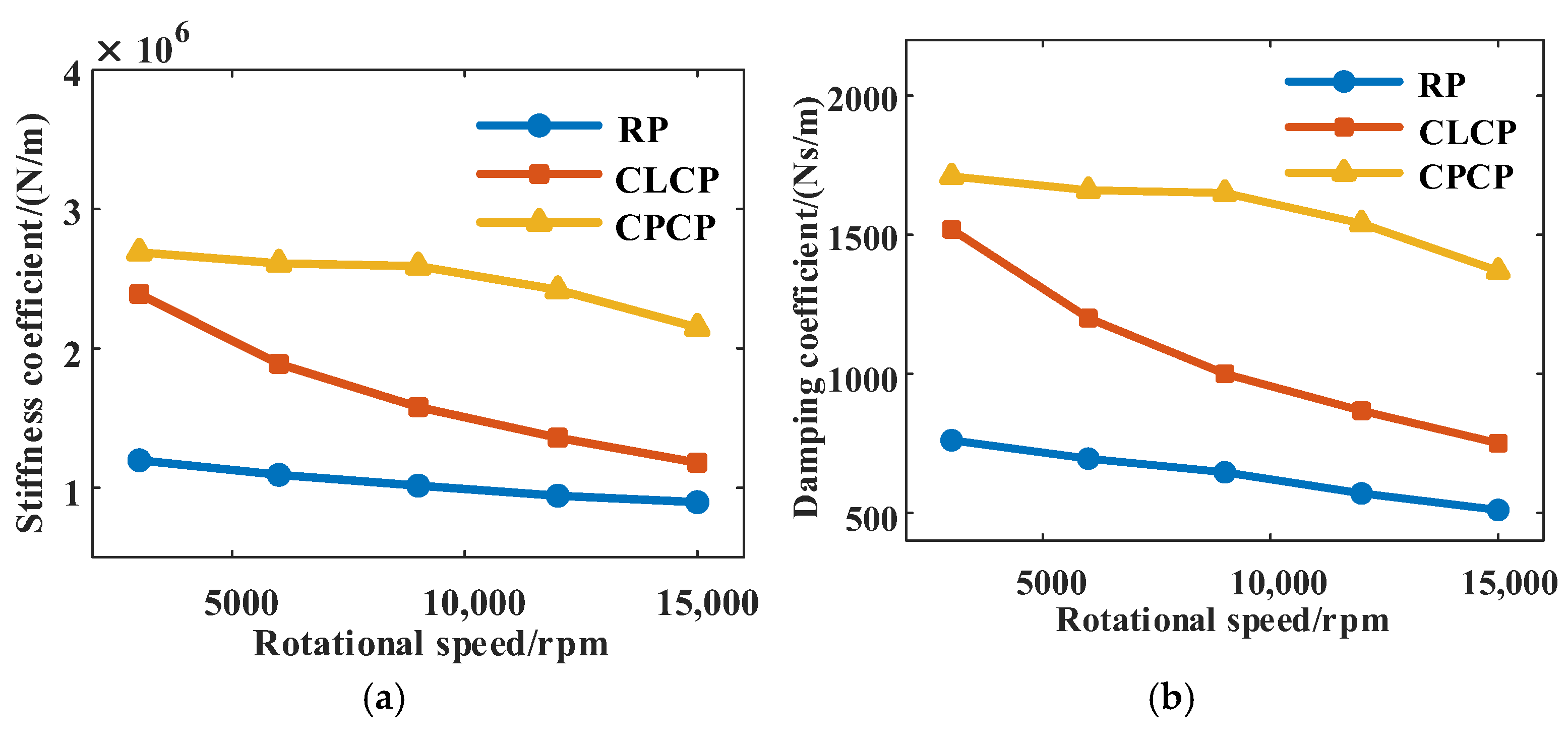
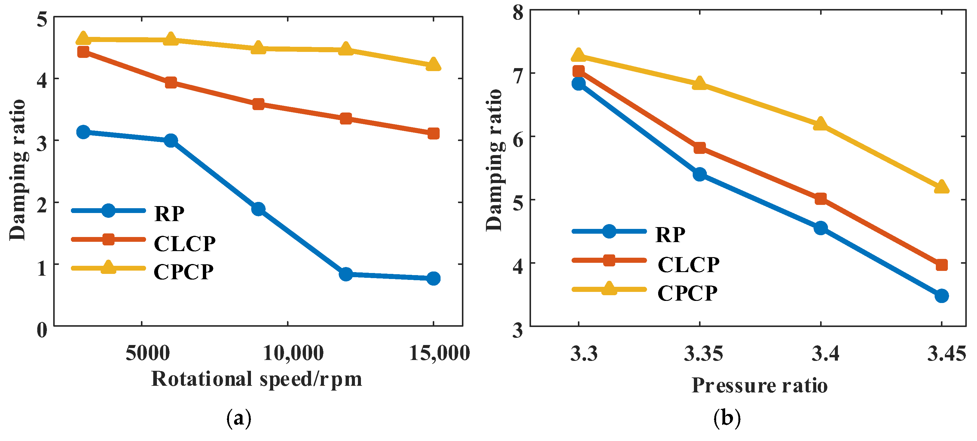
Rotational Speed
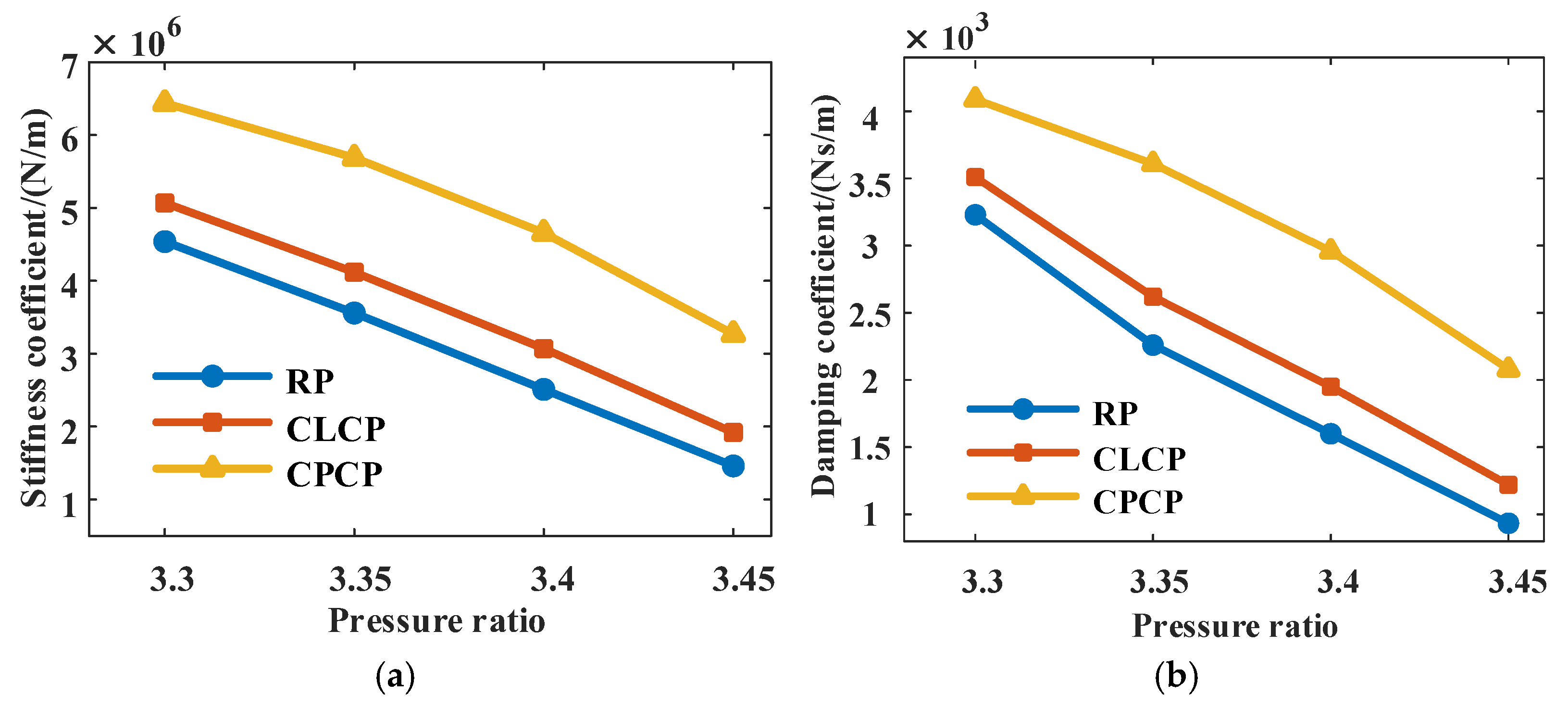
Pressure Ratio
Stability
5.2.2. Influence of Structural Parameters on Dynamic Characteristics
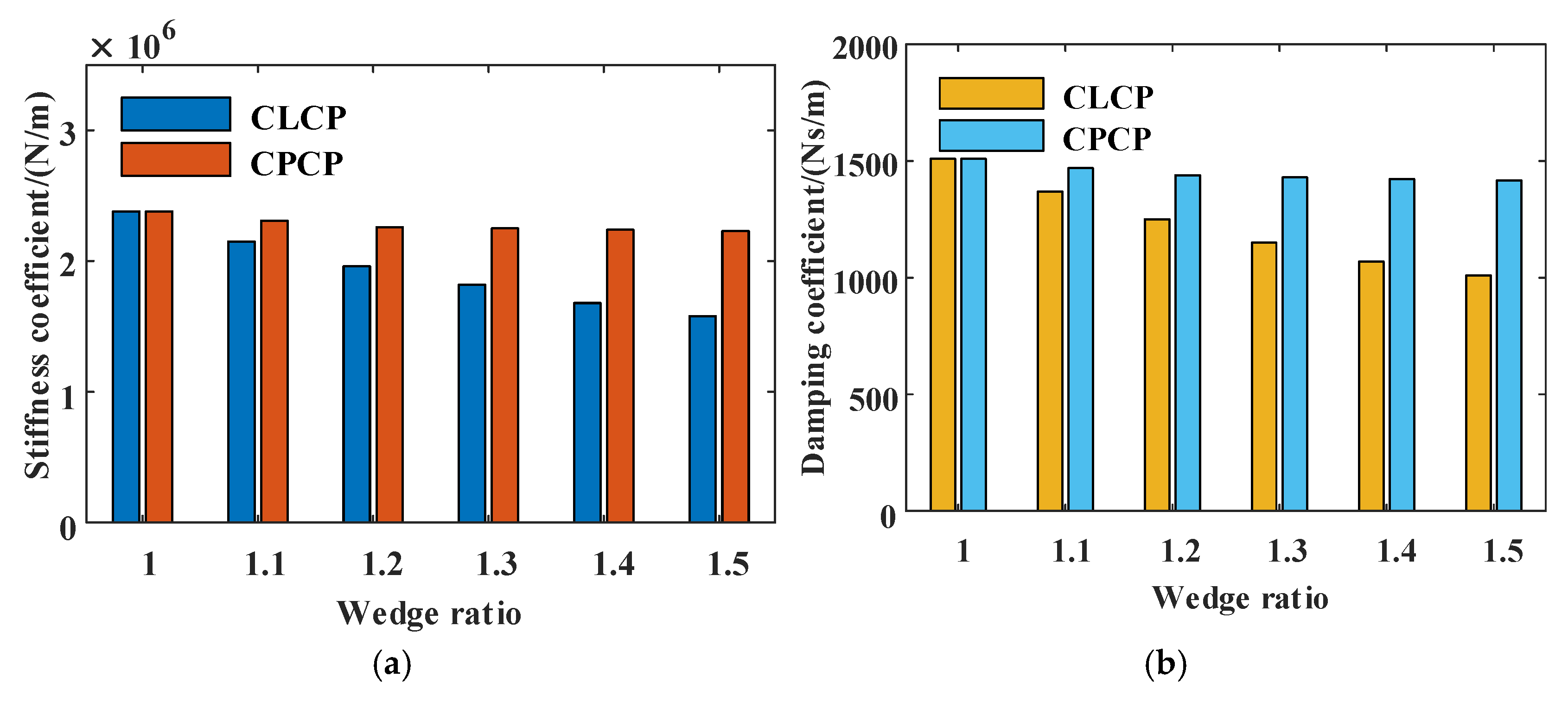
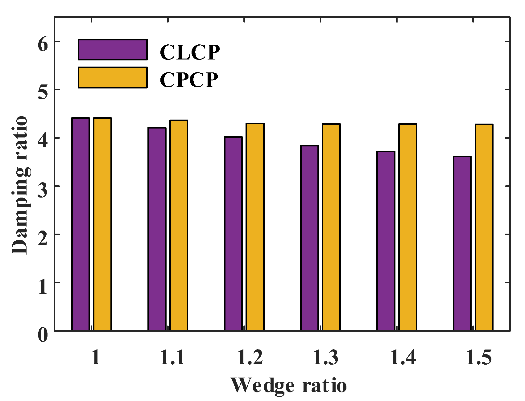
Wedge Ratio
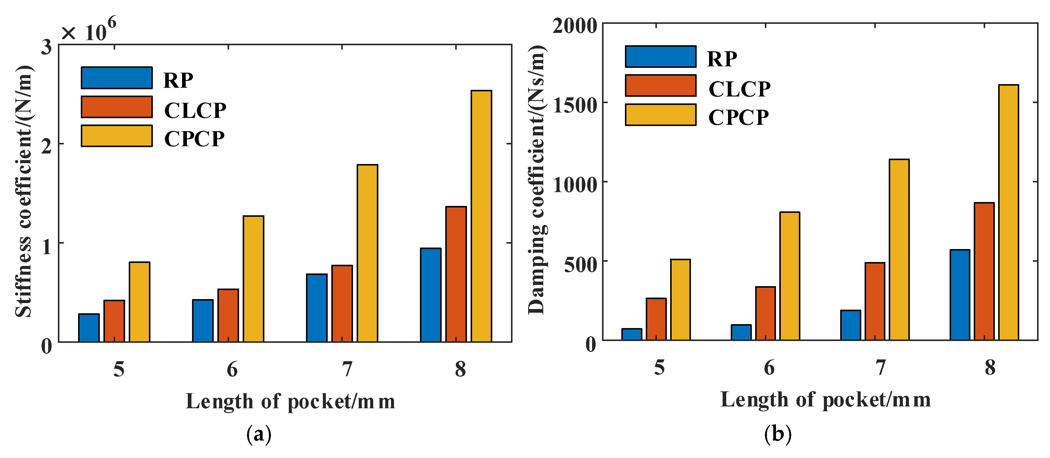
Pocket Length
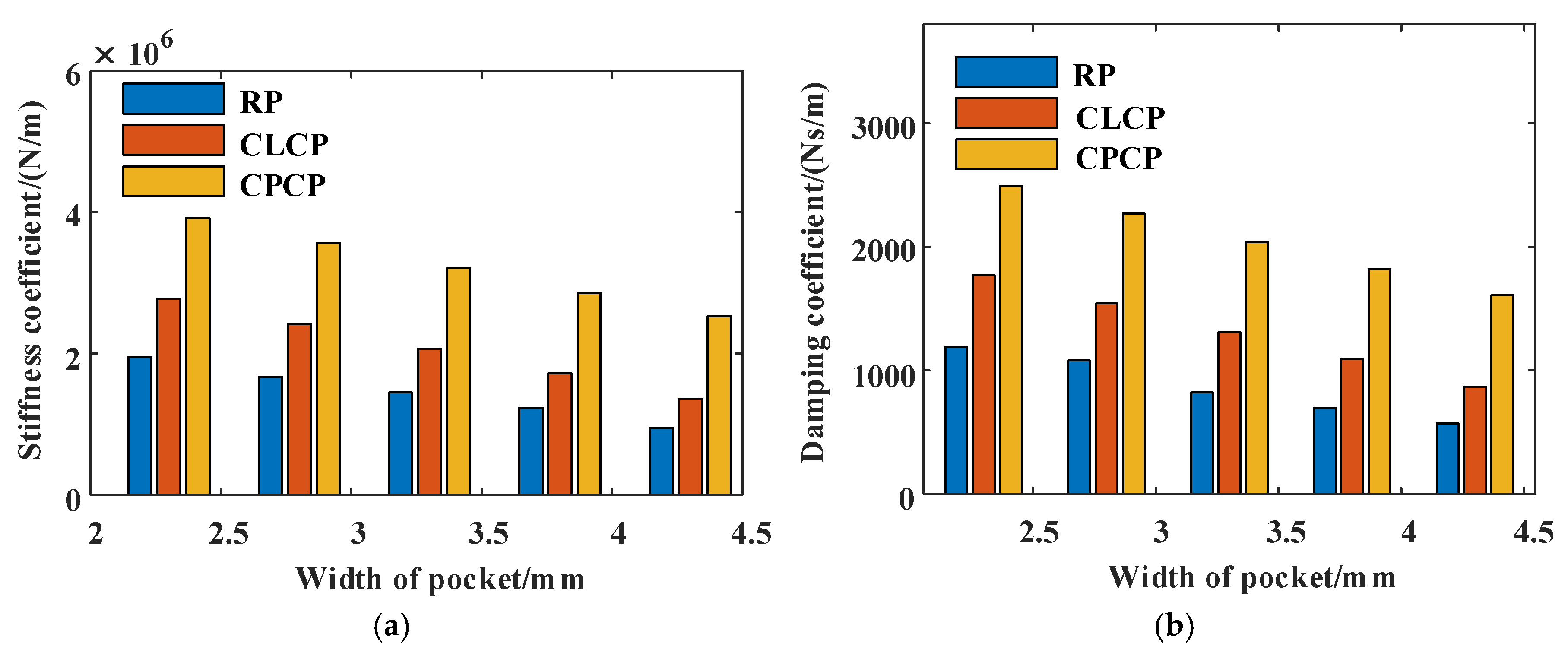
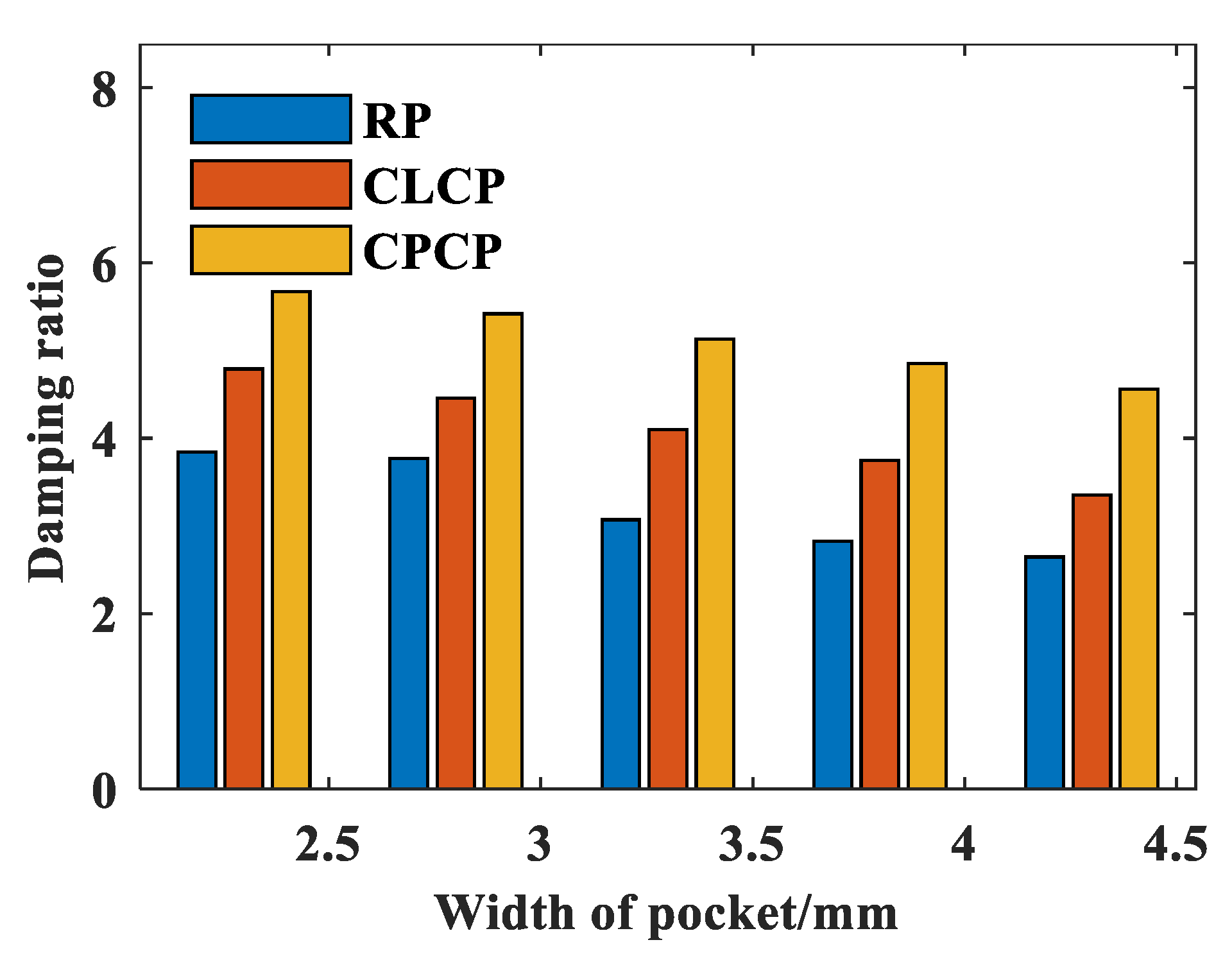
Pocket Width
6. Conclusions
- (1)
- Compared with the conventional RP, the CLCP and the CPCP can notably improve the segmented annular seal’s hydrodynamic pressure effect, enlarge the clearances, reduce the friction and improve the problem of poor dynamic characteristics.
- (2)
- With the increase in rotational speed and pressure ratio, the leakage of segmented annular seals with two wedge pocket structures is larger than that of the RP seal. The leakage of both novel seals with circumferentially convergent wedge pocket structures increases with the increase in the wedge ratio, pocket length, and pocket width.
- (3)
- Compared to the traditional RP seal, the CLCP seal has an average increase in the stiffness and damping coefficients of 60.76% and 65.27%, respectively. As the rotational speed increases, the damping ratio of the RP seal decreases, and the seal system transitions from an overdamped state to an underdamped state, resulting in reduced stability. Under different rotational speeds and pressure ratios, both of the CLCP and CPCP seals are in an overdamped state.
- (4)
- A rise in wedge ratio and pocket width is associated with diminished stiffness and damping coefficients in both CLCP and CPCP seals, while an increase in pocket length results in improved dynamic characteristics. In this study, when the static and dynamic characteristics of the seals are taken into account, the CLCP seal is identified as the most optimal structure.
Author Contributions
Funding
Data Availability Statement
Conflicts of Interest
References
- Dahite, S.; Arghir, M. Thermogasodynamic analysis of the segmented annular Seal. ASME J. Tribol. 2021, 143, 072301. [Google Scholar] [CrossRef]
- Bai, S.X.; Chu, D.; Ma, C.H.; Yang, J.; Bao, S.Y. Thermo-hydrodynamic effect of gas split floating ring seal with Rayleigh step grooves. Materials 2023, 16, 2283. [Google Scholar] [CrossRef] [PubMed]
- He, Z.P.; Jia, L.H.; Si, J.X.; Li, N.; Wang, H.Y.; Li, B.C.; Guo, Y.H.; Zhao, S.J.; Luo, W.D. Research on the sealing performance of segmented annular seals based on fluid–solid–thermal coupling model. Lubricants 2024, 12, 407. [Google Scholar] [CrossRef]
- Li, G.Q.; Zhang, S.; Kang, Z.; Zhang, Y.F.; Lu, X.G.; Zhu, J.Q. Leakage and wear characteristics of carbon seals for aero-engines. Chin J. Aeronaut. 2022, 35, 389–400. [Google Scholar] [CrossRef]
- Burcham, R.E. Segmented, Arch-Bound Carbon Seal Is Pressure Loaded; Report No.: B67-10325; NASA: Washington, DC, USA, 1967. Available online: https://ntrs.nasa.gov/search.jsp?R=19670000325 (accessed on 23 February 2025).
- Burcham, R.E. Liquid Rocket Engine Turbopump Rotating-Shaft Seals; National Aeronautics and Space Administration: Washington, DC, USA, 1978. [Google Scholar]
- Pescosolido, A.; Dobek, L. Development of high misalignment carbon seals. In Proceedings of the 37th Joint Propulsion Conference and Exhibit, Salt Lake City, UT, USA, 8–11 July 2001. [Google Scholar]
- Ludwig, L.P.; Lynwander, P. Mainshaft Seals for Small Gas Turbine Engines; National Aeronautics and Space Administration: Washington, DC, USA, 1974. [Google Scholar]
- Yang, H.W.; Bai, S.X. Gas hydrodynamic lubrication performance of split floating ring seals with Rayleigh step grooves. J. Propuls. Technol. 2022, 43, 148–154. [Google Scholar] [CrossRef]
- Arghir, M.; Mariot, A. Theoretical analysis of the static characteristics of the carbon segmented seal. ASME J. Tribol. 2017, 139, 062202. [Google Scholar] [CrossRef]
- Michaelis, S. Contaminated aircraft cabin air. J. Biol. Phys. Chem. 2011, 11, 132–145. [Google Scholar] [CrossRef]
- Zhang, F.Y.; Yang, J.M.; Shui, H.C.; Dong, C.C. Effect of roughness on sealing performance of oil seals with surface texture. Ind. Lubr. Tribol. 2020, 72, 525–532. [Google Scholar] [CrossRef]
- Goldring, E.N. Feasibility Study of Negative Lift Circumferential Type Seal for Helicopter Transmissions; Report No.: CR-135302; NASA: Washington, DC, USA, 1977. Available online: https://ntrs.nasa.gov/citations/19780009447 (accessed on 23 February 2025).
- Allen, G.P. Self-Acting Lift-Pad Geometry for Circumferential Seals: A Noncontacting Concept; National Aeronautics and Space Administration: Washington, DC, USA, 1980. Available online: https://ntrs.nasa.gov/citations/19800006146 (accessed on 23 February 2025).
- Burcham, R.E.; Diamond, W.A. High-Pressure Hot-Gas Self-Acting Floating Ring Shaft Seal for Liquid Rocket Turbopumps; National Aeronautics and Space Administration: Washington, DC, USA, 1980. Available online: https://ntrs.nasa.gov/citations/19810017923 (accessed on 23 February 2025).
- Strom, T.N.; Ludwig, L.P. Development of Circumferential Seal for Helicopter Transmission Result of Bench and Flight Tests; National Aeronautics and Space Administration: Washington, DC, USA, 1975. Available online: https://ntrs.nasa.gov/citations/19750024982 (accessed on 23 February 2025).
- Kikuchi, M.; Oike, M.; Watanabe, Y.; Nosaka, M. Durability of a Carbon Segmented Circumferential Seal for a Liquid Oxygen Turbopump; National Aerospace Laboratory: Bangalore, India, 1992. [Google Scholar]
- Oike, M.; Nosaka, M.; Watanabe, Y.; Kikuchi, M.; Kamijo, K. Experimental study on high-pressure gas seals for a liquid oxygen turbopump. Tribol. Trans. 1988, 31, 91–97. [Google Scholar] [CrossRef]
- Yuri, K.; Izhak, E. Analysis of the hydrodynamic effects in a surface textured circumferential gas seal. Tribol. Trans. 2001, 44, 472–478. [Google Scholar] [CrossRef]
- Wang, S.; Zhao, H.; Dan, S.; Xu, W.F. Theoretical analysis of gas hydrodynamic lubrication in a carbon segmented seal with the local Differential Quadrature-Lagrange method. In Proceedings of the 2023 International Symposium on Clean Energy and Advanced Materials, Hangzhou, China, 17–19 February 2023. [Google Scholar]
- Dahite, S.; Arghir, M. Numerical modelling of a segmented annular seal with enhanced lift effects. Mech. Syst. Signal Process. 2021, 152, 107455. [Google Scholar] [CrossRef]
- Wang, S.; Sun, D.; Yang, Z.M.; Xu, W.F.; Zhao, H.; Wen, S.F. Investigation of static and dynamic characteristics of the segmented annular seals based on the differential quadrature method. Tribol. Int. 2024, 196, 109657. [Google Scholar] [CrossRef]
- Li, G.Q.; Zhu, J.Q.; Xu, G.; Lu, X.G.; Zhang, Y.F. A Graphite Sealing Structure with Anti-Fishbone Dynamic Pressure Groove. CN 111927633A, 20 August 2020. [Google Scholar]
- Li, G.Q.; Zhu, J.Q.; Xu, G.; Lu, X.G.; Zhang, Y.F. A Graphite Sealing Structure with Diagonal Dynamic Pressure Grooves. CN 111927635A, 20 August 2020. [Google Scholar]
- Sun, D.; Wang, S.; Fei, C.W.; Ai, Y.T.; Wang, K.M. Numerical and experimental investigation on the effect of swirl brakes on the labyrinth seals. ASME J. Eng. Gas Turbines Power 2016, 138, 032507. [Google Scholar] [CrossRef]
- Guo, Z.L.; Hirano, T.; Kirk, R.G. Application of CFD analysis for rotating machinery-Part I: Hydrodynamic, hydrostatic bearings and squeeze film damper. ASME J. Eng. Gas Turbines Power 2005, 127, 445–451. [Google Scholar] [CrossRef]


| Item | Seal with the RP | Seal with the CLCP | Seal with the CPCP |
|---|---|---|---|
| Depth of RP/mm | 0.015 | — | — |
| Circumferential convergent pocket depth 1/mm | — | 0.010 | 0.010 |
| Circumferential convergent pocket depth 2/mm | — | 0.025 | 0.025 |
| Item | Value | Item | Value |
|---|---|---|---|
| Rotational speed n/r·min−1 | 3000~15,000 | Outlet pressure p0/MPa | 0.10 |
| Pressure ratio (P.R.) | 3.30~3.45 | Air dynamic viscosity/Pa·s | 1.83 × 10⁻⁵ |
| Spring force Fs/N | 0.36, 0.315 |
Disclaimer/Publisher’s Note: The statements, opinions and data contained in all publications are solely those of the individual author(s) and contributor(s) and not of MDPI and/or the editor(s). MDPI and/or the editor(s) disclaim responsibility for any injury to people or property resulting from any ideas, methods, instructions or products referred to in the content. |
© 2025 by the authors. Licensee MDPI, Basel, Switzerland. This article is an open access article distributed under the terms and conditions of the Creative Commons Attribution (CC BY) license (https://creativecommons.org/licenses/by/4.0/).
Share and Cite
Wang, S.; Sun, D.; Yang, Z.; Xu, W.; Zhao, H. Influence of Circumferential Convergent Wedge Pocket on the Segmented Annular Seal’s Static and Dynamic Characteristics. Lubricants 2025, 13, 121. https://doi.org/10.3390/lubricants13030121
Wang S, Sun D, Yang Z, Xu W, Zhao H. Influence of Circumferential Convergent Wedge Pocket on the Segmented Annular Seal’s Static and Dynamic Characteristics. Lubricants. 2025; 13(3):121. https://doi.org/10.3390/lubricants13030121
Chicago/Turabian StyleWang, Shuang, Dan Sun, Zemin Yang, Wenfeng Xu, and Huan Zhao. 2025. "Influence of Circumferential Convergent Wedge Pocket on the Segmented Annular Seal’s Static and Dynamic Characteristics" Lubricants 13, no. 3: 121. https://doi.org/10.3390/lubricants13030121
APA StyleWang, S., Sun, D., Yang, Z., Xu, W., & Zhao, H. (2025). Influence of Circumferential Convergent Wedge Pocket on the Segmented Annular Seal’s Static and Dynamic Characteristics. Lubricants, 13(3), 121. https://doi.org/10.3390/lubricants13030121