Abstract
The protective coatings industry is expanding, offering significant improvements in abrasion and wear resistance, which are crucial for economic sustainability. Despite the advancements, there remains a research gap in understanding the tribological properties and surface morphologies of electroless Ni-P and Ni-B coatings. This study aims to fill this gap by characterizing the surface structures, friction coefficients, and wear properties of two types of Ni-P and one type of Ni-B coatings. Using a ceramic ball counterpart in an SRV5 tribometer, we compared the wear rates according to Archard’s and Liu’s models, adhering to the DIN 51834-1 standard. Scanning electron microscopy was employed to analyze the impact of surface structures on friction coefficients and wear factors. The results reveal significant differences in wear resistance and friction behaviour among the coatings, providing valuable insights for their application in various industries.
1. Introduction
Surface protection, such as corrosion resistance and tribological properties of metallic parts, equipment, and tools used in various industrial fields, is important. The mechanical and tribological properties of bulk materials can be improved by different surface modification techniques such as laser/flame hardening [1,2], carburizing [3], nitriding [4], or by applying coating processes [5]. Physical vapour deposition (PVD) and chemical vapour deposition (CVD) have gained popularity in industrial applications. However, they are also rather expensive and time-consuming technologies [6,7,8,9,10]. Another option is the deposition from aqueous solutions, such as electrodeposition and electroless method [11]. Electroless processes are preferred due to good adhesion properties and the formation of uniform coating thickness (even with complex geometries) [12]. Among them, electroless Ni alloys, namely Ni-P and Ni-B, have the broadest applications [13,14,15]. Electroless deposition is an autocatalytic process without the need for an external power source, where the film deposition takes place through the reduction in the metallic ions in the solutions through the oxidation of a chemical compound (reductant/reducing agent) that provides an internal current. The reductant oxidizes catalytically on the surface of the substrate, which can occur spontaneously or after an appropriate surface activation [16]. Once the deposition is initiated, the process continues automatically [12,17]. When the reducing agent is sodium hypophosphite, Ni-P coatings can be obtained, while for Ni-B, borohydrides or dimethylamine borane (DMAB) can be used as reductants.
Electroless Ni-P coatings exhibit good corrosion resistance, especially with high P-content, wear resistance, and sufficiently high hardness [17,18]. They also offer good lubricious properties and excellent solderability, which make them desirable for different industrial fields, such as chemical, oil, aerospace, and electronic industries [19,20]. While electroless Ni-B coatings are well known for their high hardness [21], wear resistance, and superior abrasion resistance [22], they also possess a columnar structure and cauliflower-like surface morphology, thereby increasing their lubrication properties [23]. The hardness of the coatings can be increased by heat treatment via the formation of NixPy and NixBy intermetallic compounds. Another way to improve the mechanical properties of electroless Ni coatings is the co-deposition of hard (e.g., Al2O3, SiC, TiC, ZrO2) and soft (e.g., CNT, graphene, PTFE) particles, thus creating composite coatings [24,25,26]. Electroless Ni coatings also offer interesting functional properties such as catalytic activity and energy storage capability, thus finding their application as supercapacitors [27,28], catalytic electrodes [29], and flexible conductive materials [30]. The properties of electroless Ni coatings are strongly affected by the alloying element and its concentration. With increasing P and B content, the structure of the coatings transforms from micro/nanocrystalline to amorphous [31]. The tensile strength of Ni-P is also dependent on the P content, which is usually higher than for Ni-B [32]. Ni-P and Ni-B coatings are widely used in industrial applications due to their excellent mechanical properties and corrosion resistance. Wang et al. [33] investigated the effect of nanoscale surface roughness on sliding friction and wear in mixed lubrication regimes. They found that nanoscale roughness significantly influences the friction coefficient, with smoother surfaces exhibiting lower friction due to better lubricant film formation. Park et al. [34] reviewed the tribological properties of various materials, including the impact of surface roughness on friction. They highlighted that the relationship between roughness and friction is not linear; instead, it follows a curvilinear trend where friction initially increases with roughness, reaches a peak, and then decreases as roughness continues to increase. Khaday et al. [35] examined the relationship between friction coefficient and surface roughness of stone and ceramic floors. They validated the curvilinear relationship, showing that friction increases with roughness up to a certain point, after which it stabilizes or decreases.
The paper aims to investigate the influence of Ni-P and Ni-B coatings on the microstructure, mechanical properties and tribological properties for three types of coatings on steel substrates. The surface morphologies were compared for different coatings. SRV wear tests were conducted using a ZrO2 counter ball. The coefficient of friction and the wear volume loss were collected from the wear tests carried out and calculated according to the DIN 51834-1 standard [36]. Two wear coefficients were determined and compared, as obtained by Ravikiran [37] and Liu [38], applying the volume loss and the sliding distance.
2. Experiments
In the experiments, the composition and hardness of the surface layer on two different Ni-P and Ni-B coated steel discs were investigated, and an oscillating motion ball-on-plate test was performed. The latter test was used to determine the behaviour of the friction coefficients, and the resulting wear track was used to measure the wear volume by metallography.
2.1. Preparation of Test Specimens
Ni-P and Ni-B coatings were deposited on the surface of disc specimens using the electroless method. The discs are made of a C45E steel grade and are characterized by a 24 mm diameter and a 7.8 mm thickness. All substrates were first polished and then ultrasonically cleaned in acetone for 2 min, distilled water rinsing, and alkaline degreasing in 10 wt.% NaOH solution at 80 °C for 10 min, distilled water rinsing, activation in cc. HCl (37 wt.%) for 30 s, distilled water rinsing, and sensitization in PdCl2 solution for 30 s.
2.2. Coating Methods
Ni-P coatings were deposited from two different types of acidic baths, while Ni-B coatings were deposited from an alkaline bath. The composition and operating conditions of the Ni-P and Ni-B electroless baths are listed in Table 1 and Table 2, respectively.

Table 1.
Bath compositions and operating conditions of electroless Ni-P coatings.
Table 2.
Bath composition and operating conditions of electroless Ni-B coating.
2.3. The Coating Thickness
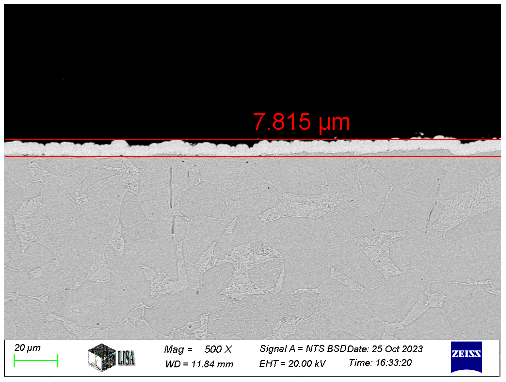
The thickness of the coatings was measured by ZEISS EVO MA10 scanning electron microscopy (SEM) of the cross-sections for the tested coatings (see Figure 1). The average coating thickness measured for the different types of coatings is shown in Table 3.

Figure 1.
Ni-B coating cross-section at 500× magnification.
Table 3.
The average coating thickness [μm].
2.4. The Surface Morphologies
The morphological analysis of the coatings on the specimens was conducted using SEM. In addition to examining the coating morphology, the chemical composition of the surface was analyzed across a range of atomic numbers.
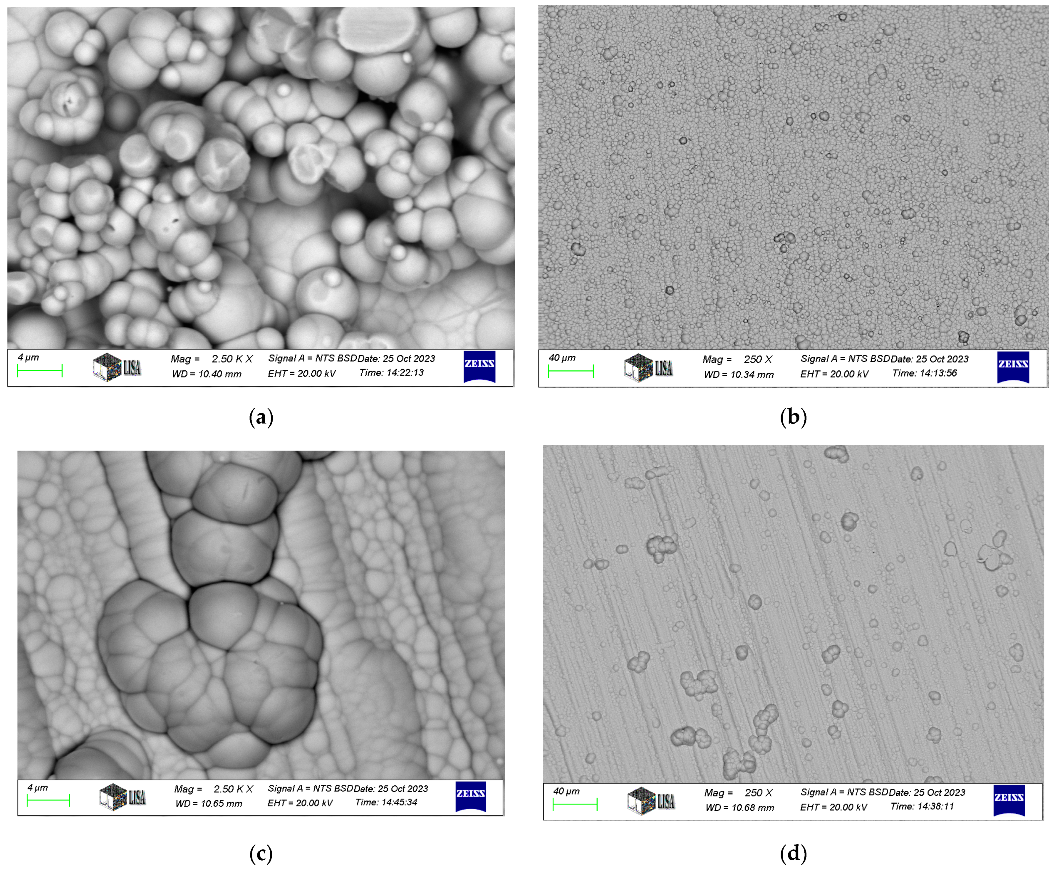
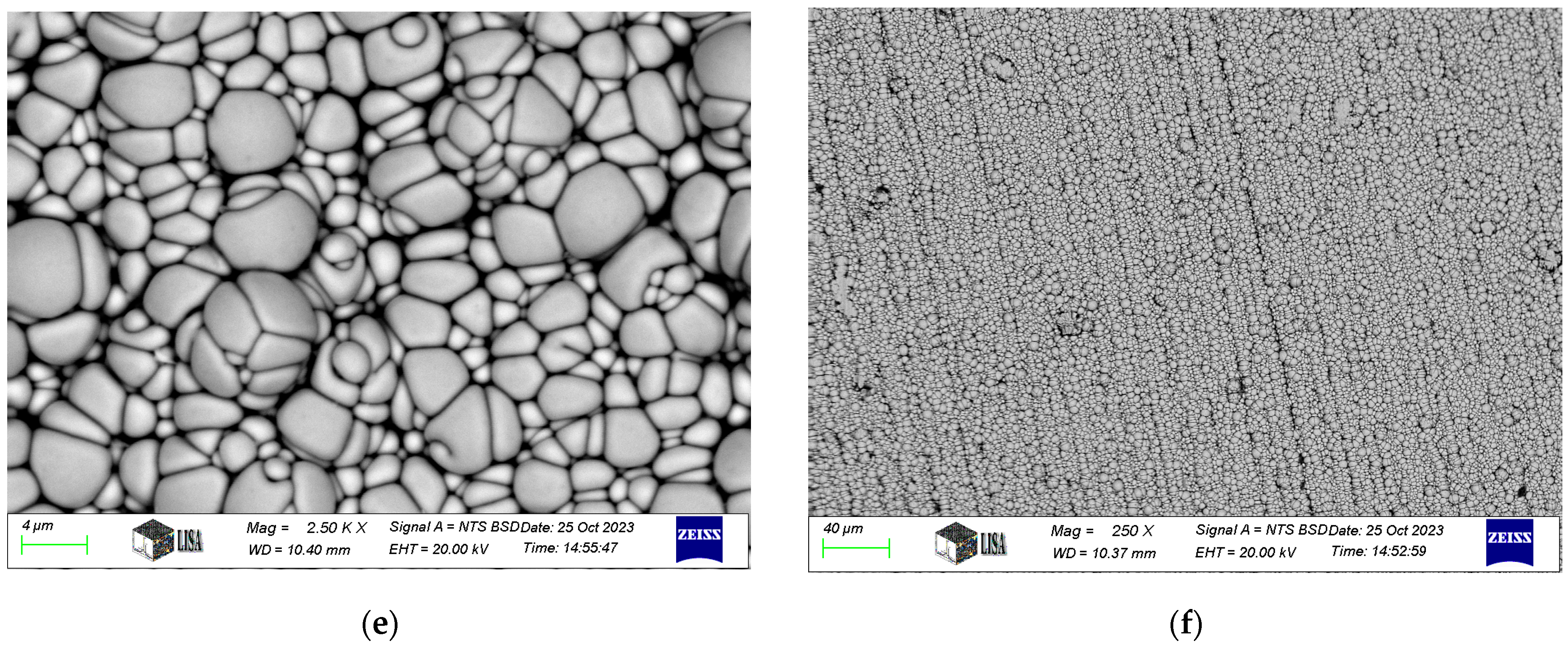
Typical SEM images of electroless nickel coatings are presented in Figure 2. The coating exhibits a blackberry-like morphology for Ni-P-I, a cauliflower-like structure for Ni-P-II, and a pebble-like appearance for Ni-B, consistent with the findings of Bulbul [39]. Similar surface morphologies have been reported in other studies. For instance, Ahmed et al. [23] found that Ni-P/Ni-B duplex coatings exhibited a characteristic cauliflower morphology and spherical nodular structures. Tohidi et al. [40] also observed that Ni-P/Ni-B duplex coatings had a more compressed surface morphology compared to single-layer Ni-B coatings. Microscopic examination further reveals that the coating conforms to the structure of the machining edges.
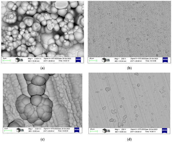
Figure 2.
SEM images of electroless nickel coatings: (a,b). Ni-P-I coating, (c,d). Ni-P-II coating, (e,f). Ni-B coating.
2.5. Wear Volume Calculated
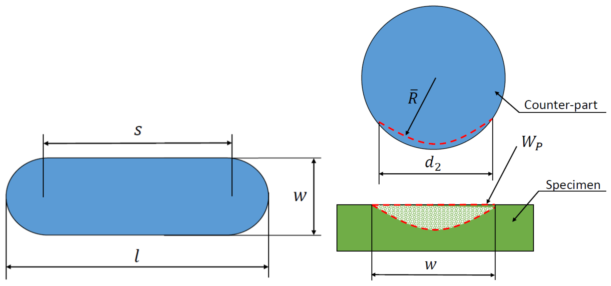
A comparison of the measured data and the wear volume loss calculated according to DIN 51834-1 is performed [36]. The wear volume loss is determined as the wear of the test specimen and the counterpart is taken into account. The interpretation of the notations used for the calculation of the wear volume loss is illustrated in Figure 3.
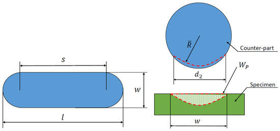
Figure 3.
Representation of wear volume according to DIN 51834-1.
The wear volume of the counterfill can be calculated using the equation
where is the diameter of the wear mark on the counterface parallel to the wear direction [mm], denotes the diameter of the wear mark on the counterface perpendicular to the abrasion direction [mm], R is the radius of the counter-ball before measurement [mm], is the average radius of the counter-flange after the abrasion test [mm]. The average radius after the abrasion test can be determined as a function of
where is the amount of abrasion perpendicular to the abrasion direction [mm2].
For , the equation can be applied for uniform wear of a spherical counterbore. If the wear of the counter-ball is negligible, then the wear of the test piece due to , then ,
where the amount of wear on the plane can be defined as
where (see Figure 4).
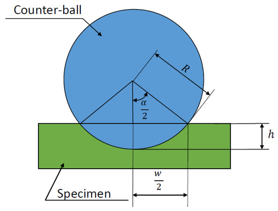
Figure 4.
Geometric representation of the determination of the planar wear rate.
3. Results and Discussion
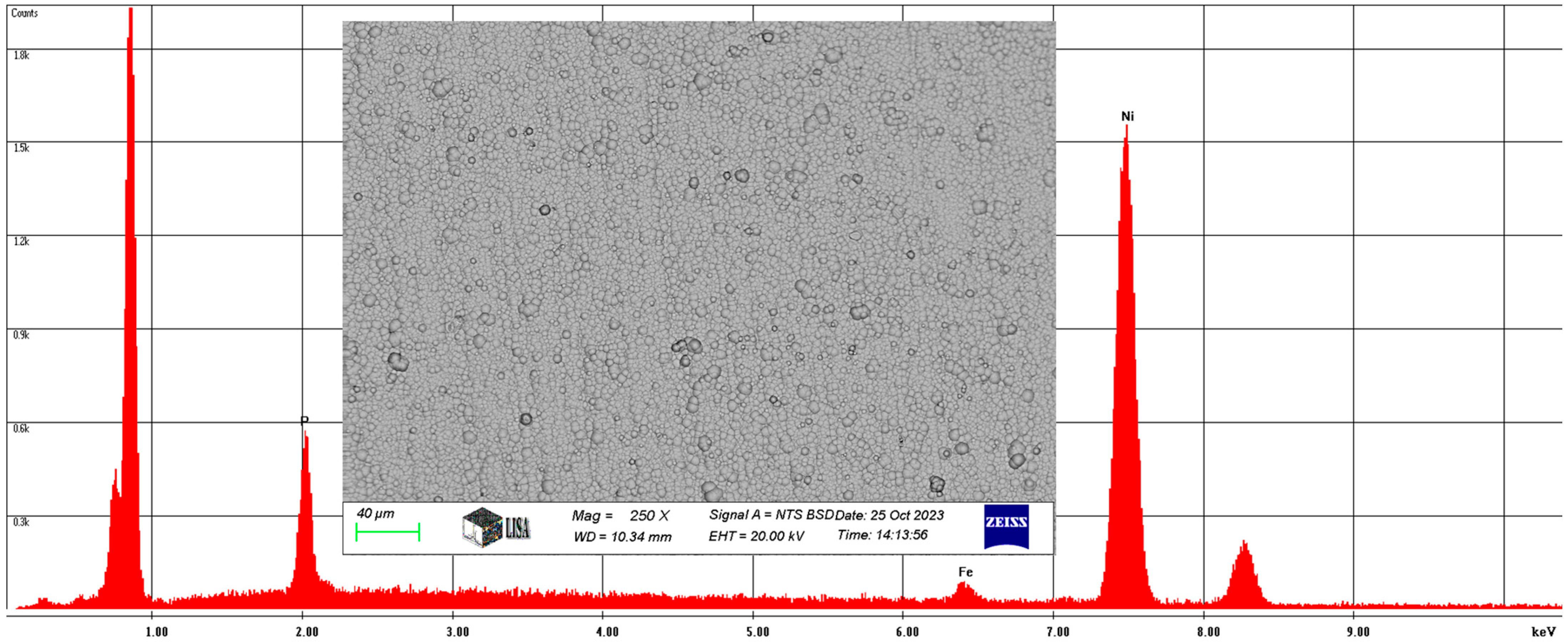
3.1. Chemical Composition
The chemical composition was measured by SEM. For the Ni-P-I coating, the average chemical composition of the coating area of 145,250 was analyzed at 250× magnification, as illustrated in Figure 5. On average, the coating contains 6.66 w% phosphorus, 1.92 w% iron, and 91.42 w% nickel, with the same elements having a phosphorus content of 11.89 at%, an iron content of 1.91 at%, and a nickel content of 86.2 at%.
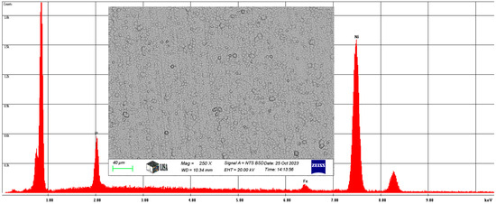
Figure 5.
The average chemical composition of the Ni-P-I coating resulted from SEM analysis.
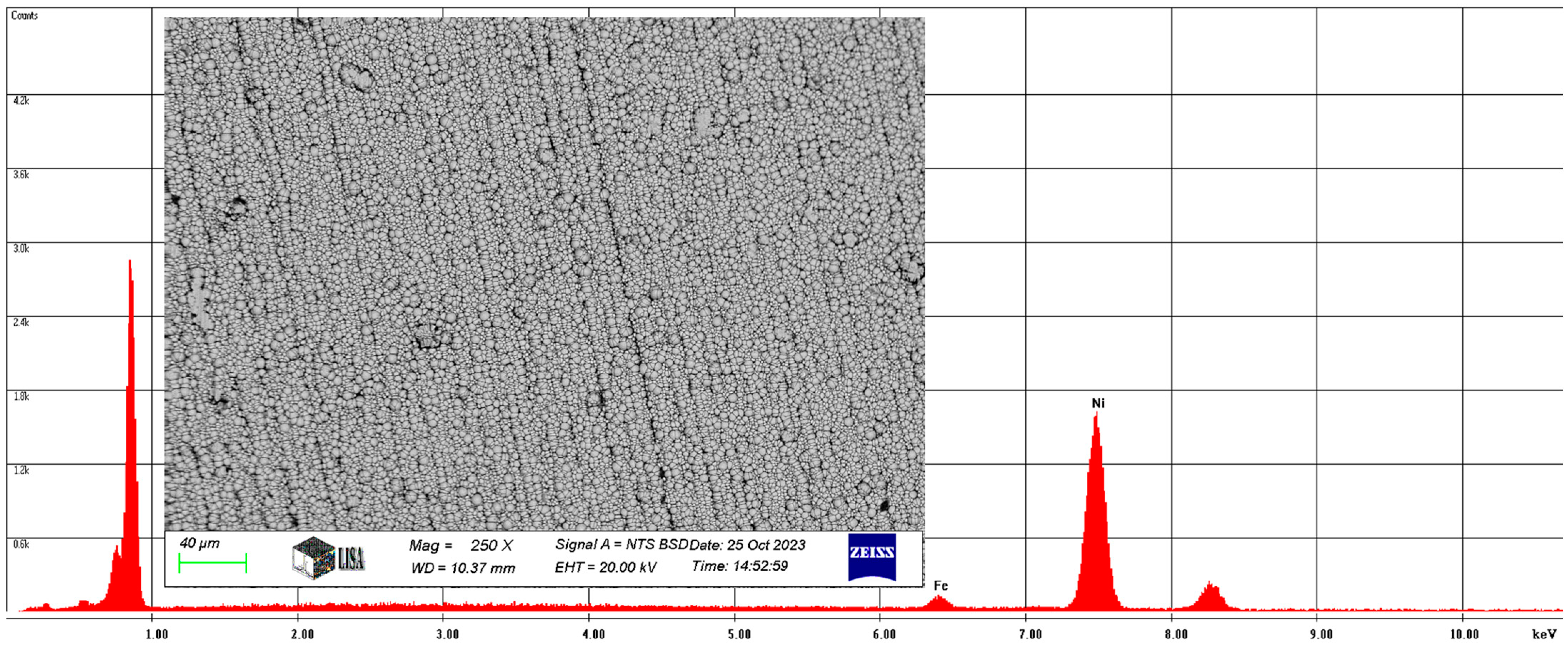
Also, for the Ni-P-II coating, the average chemical composition of the coating was analyzed at 250× magnification and is illustrated in Figure 6.
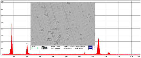
Figure 6.
The average chemical composition of the Ni-P-II coating resulted from SEM analysis.
On average, the Ni-P-II coating contains 11.56 w% phosphorus, 2.88 w% iron, and 85.56 w% nickel, with the same elements having a phosphorus content of 11.82 at%, an iron content of 2.74 at%, and a nickel content of 77.44 at%.
Also, the average chemical composition of the Ni-B coating was analyzed at 250× magnification. The results of the study are illustrated in Figure 7.
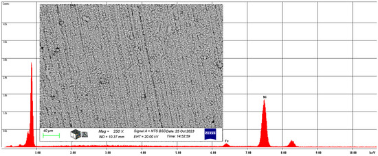
Figure 7.
The average chemical composition of the Ni-B coating resulted from SEM analysis.
On average, the Ni-B coating contains 2.94 w% iron and 97.06 w% nickel, with the same elements containing 3.08 at% iron and 96.92 at% nickel. Of course, the coating contains boron, but the atomic number of boron is five, which is outside the range of atomic numbers detected by the scanning electron microscope.
The chemical compositions reported in this study are consistent with those found in other studies. For instance, Tohidi et al. reported similar phosphorus and nickel contents in their Ni-P and Ni-B coatings [40].
3.2. Microhardness
The microhardness was determined for three different coatings (Ni-P-I, Ni-P-II and Ni-B). The measurement of the microhardness of the tested coatings was carried out with a Mitutoyo MVK-H1 microhardness tester. The HV 0.01 microhardness was measured using the following measurement parameters according to ISO 6507-1:2023 [41] at an ambient temperature of 23 °C, time from the start of the load to full load 6 s, a penetration velocity of 0.1 mm/s, and a load hold time of 8 s. The microhardness of the coated surface of the specimens was tested using a load of 0.09807 N.
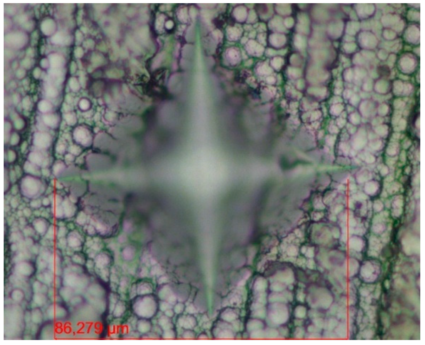
Figure 8 shows a microscopic image of the Ni-P-I specimen’s Vickers pyramid indentation. The measured microhardness values are also summarized in Table 4.

Figure 8.
Microscopic image of the pyramid indentation of a Vickers hardness test on Ni-P-I coating.
Table 4.
Average microhardness of tested coatings.
As a result of the microhardness measurements, it can be concluded that the Ni-P-I coating has the highest microhardness with a value of 543 HV 0.01, while the Ni-B coating has the lowest microhardness with a value of 429 HV 0.01. The microhardness of the Ni-P-II coating is 499 HV 0.01 (see Table 4). These Vickers microhardness values are shown as the average of the measured values.
We note that Tohidi et al. [40] reported that the hardness of Ni-P/Ni-B duplex coatings was higher than that of single-layer Ni-B coatings. This is consistent with your findings that Ni-P coatings generally exhibit higher hardness than Ni-B coatings.
3.3. Coefficient of Friction (COF)
The wear tests were carried out using an Optimol SRV5 tribometer (Optimol, Munich, Germany) suitable for tribological simulations, measurement, and testing. In the test procedure, a ball-on-plate design was used, where the contact surfaces performed a linear, oscillating motion. No lubricant was used between the contact surfaces during the tests. The exact parameters of the motion and loading, as well as the material of the counter-body, were determined in preliminary experiments.
The optimal measurement parameters were determined by employing test measurements for the load and frequency, and selecting the optimal counter-body. Two counter-bodies were tested for the appropriate counter-body. One of them is the 100 Cr6 forged bearing steel ball, which is a low alloy tool steel with a chemical composition of 0.9–1.05 C%, 0.4–0.6 Si%, 0.8–1.0 Mn%, 1.3–1.65 Cr%, <0.02 P%, and <0.02 S%. High carbon content gives it good persistence. The second one is the ZrO2 grinding ball, a very hard, solid material that can also cut steel. It is a material with high flexural strength and hardness, and in fact, it is porcelain, which is also used to make dentures and crowns. The composition of the ball used is 94.2–95.2 ZrO2%, 1–2 HfO2%, 3.5 MgO%, 0.1 SiO2%, 0.1 Al2O3%, others: 0.1%. Zirconia or ceramic ball density is 5.7 g/cm3, Vickers hardness is 1200 HV10 [42].
The 100 Cr6 forged bearing steel ball was found to have a high degree of wear and smearing while failing to produce any measurable wear on the coated surface specimens. In the case of the ZrO2 counter-body, a significant degree of wear was observed on the surface of the coated specimens. Preliminary experiments were carried out to determine test parameters to compare the different coatings, with which ø 10 mm Fritsch ball, a load of 15 N, oscillating measurement amplitude 5 mm at a frequency of 10 Hz, measurement duration 1800 s were found to be the measurement parameters for which the wear track could be evaluated. The wear test was carried out with 15 specimens (5 from each type of coating). Two wear tests were performed on each specimen. The coefficient of friction and the wear volume were measured.
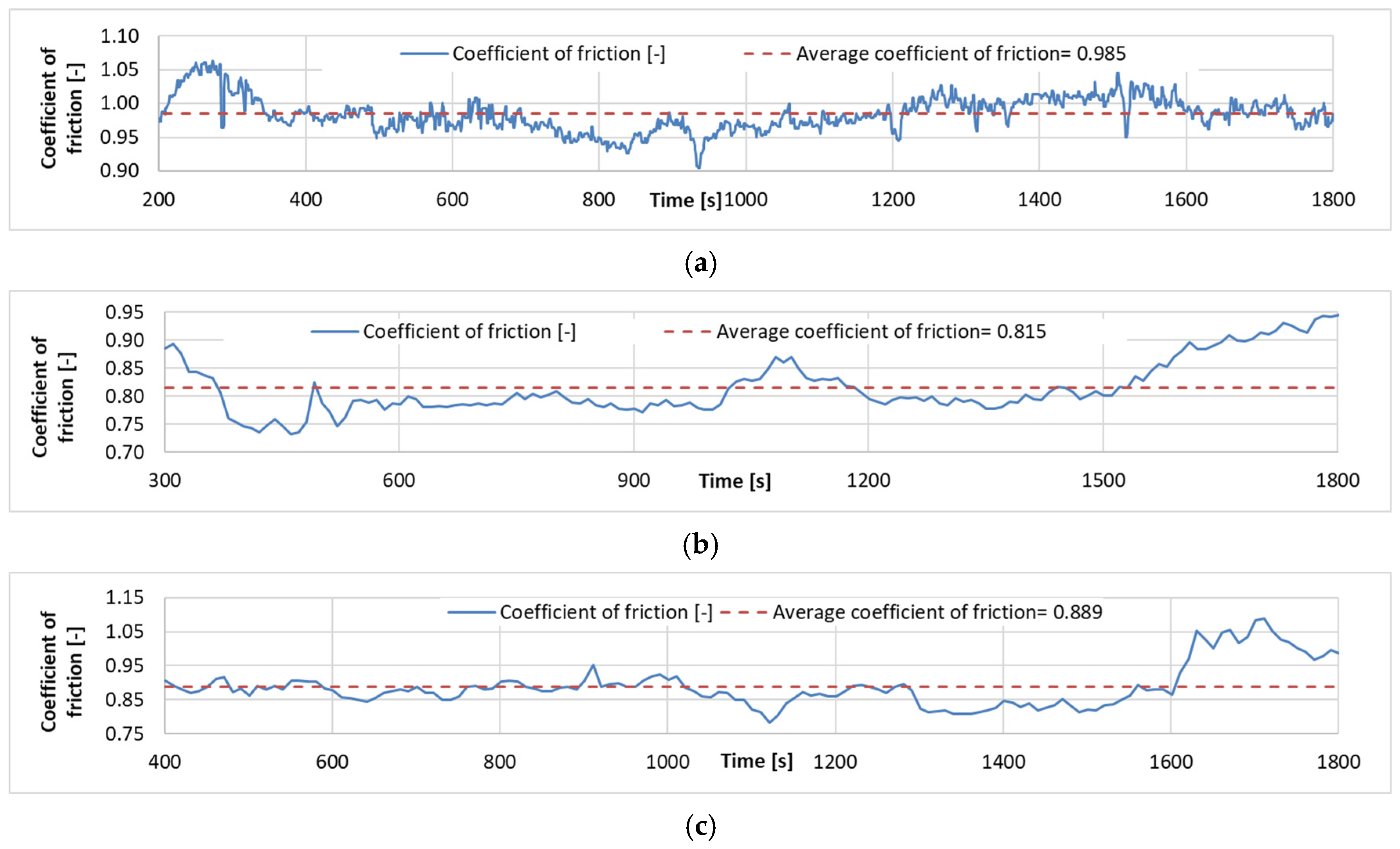
Examples of the time friction coefficient diagrams for the wear tests carried out for each coating are shown in Figure 9, while the measurement results are summarized in Table 5.
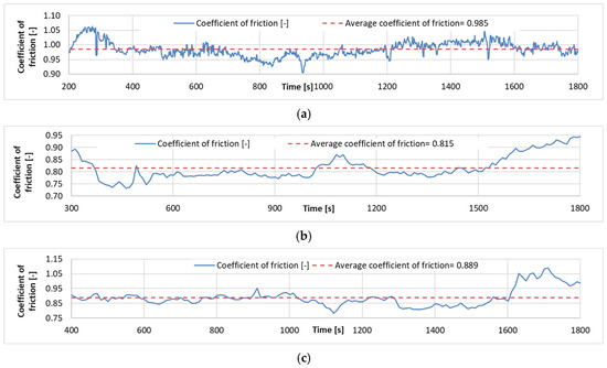
Figure 9.
Coefficient of friction time diagrams of wear tests: (a). Specimen with Ni-P–I coating (b). Specimen with Ni-P–II coating. (c). Specimen with Ni-B coating.
Table 5.
Summary of COF results.
It is found that the lowest coefficient of friction is found for Ni-P-II coating, while the highest coefficient of friction in the wear test is found for Ni-P-I coating. The surface morphology and the resulting contact geometry between the ball and the coated surface create a very high COF during motion. The COF curves show that the coatings wear off significantly as the Fe matrix-ZrO2 ball contact becomes dominant. This shows a significant increase at the end of the Ni-P-II and Ni-B COF curves compared to the previous characteristic value, and this result is also in agreement with the results of the SEM analysis of the wear tracks.
Similar trends have been observed in other studies. For example, Ahmed et al. [23] noted that the COF of Ni-P/Ni-B duplex coatings was lower than that of single-layer Ni-B coatings.
3.4. Wear Analysis
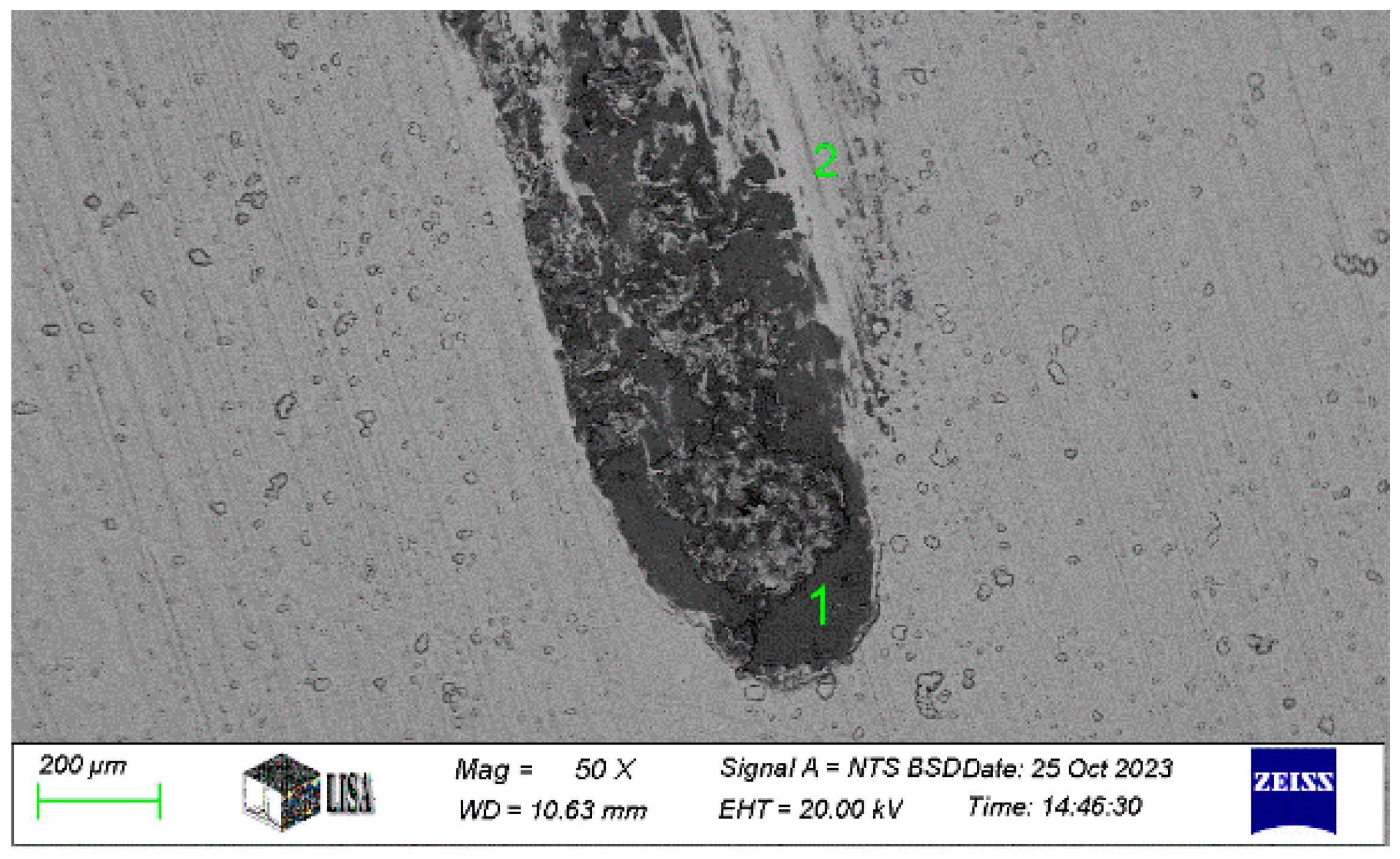
In the case of the Ni-P-I coating, the next analysis was performed on the 50× magnification image of the wear track to analyze the chemical composition of area 1, illustrated in Figure 10.
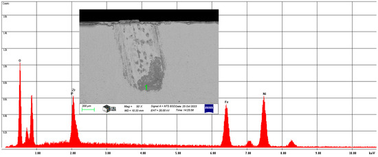
Figure 10.
The chemical composition of area 1 in the wear track of the Ni-P-I-1 coating resulted from SEM analysis.
The wear track contains, on average, 16.63 w% oxygen, 1.93 w% phosphorus, 13.91 w% zirconium, 22.96 w% iron, and 44.57 w% nickel. This confirms that the ceramic ball was smeared during the wear test.
In the case of the Ni-P-I coating, the chemical composition was analyzed at three characteristic areas on the 1500× magnification image of the wear track (see Figure 10). The SEM analysis in Figure 11 is labelled as follows: 1 = coating, 2 = worn coating, ceramic ball slightly smeared, 3 = worn coating, ceramic ball heavily smeared. The measurement results are shown in Table 6. Where the iron content is exceptionally high, the coating has already worn off, at least partially, which explains the observed composition.
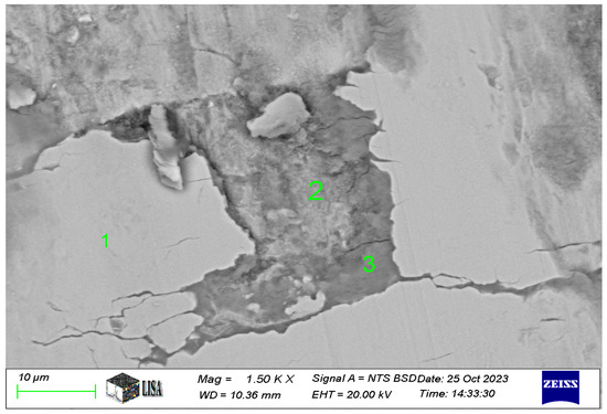
Figure 11.
The chemical composition of areas 1 to 3 in the wear track of the Ni-P-I coating resulted from SEM analysis.
Table 6.
Chemical composition of wear track on Ni-P-I-1 coating (see measuring points in Figure 11).
For the Ni-P-II coating, the chemical composition at the end and at the edge of the wear track was next measured on a 50× magnification image of the wear track (see Figure 12). The measurement results are summarized in Table 7.
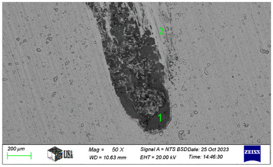
Figure 12.
The chemical composition of area 1 (wear track) and area 2 (near the wear track) of the Ni-P-II coating resulted from SEM analysis.
Table 7.
Chemical composition of the wear track and its environment on Ni-P-II-2 coating (see measuring points in Figure 12).
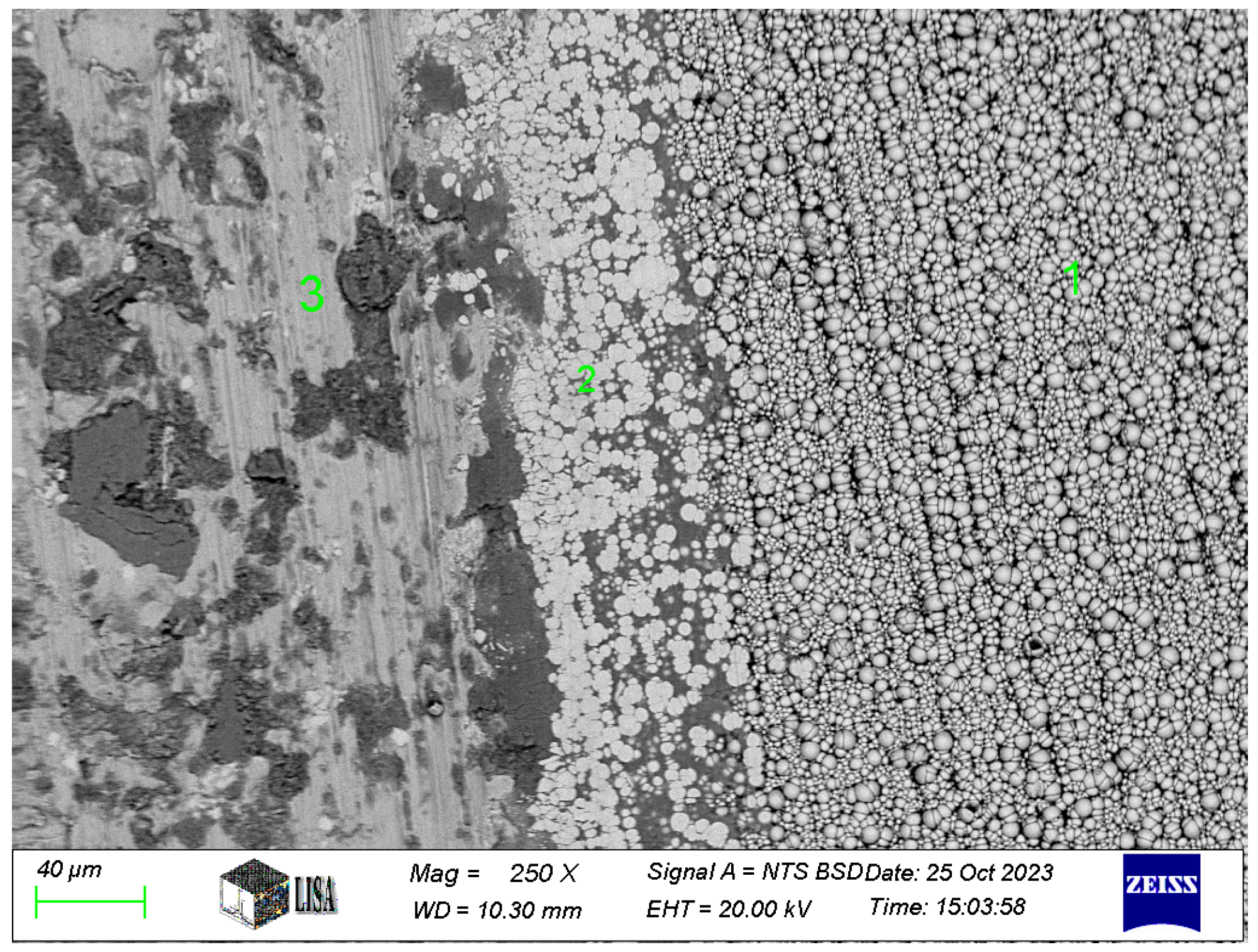
For the Ni-B coating, the chemical composition in the wear track, at the transition between the wear track and the intact coating and on the intact coating, was next measured on the image of the wear track at 250× magnification. The results of the measurements are shown in Table 8, and the 250× magnification image of the worn track is shown in Figure 13. The figure is labelled as follows: 1 = intact coating, 2 = wear track surroundings with slight coating abrasion, 3 = wear track.
Table 8.
Chemical composition of wear track on Ni-B-3 coating (see measuring points in Figure 13).
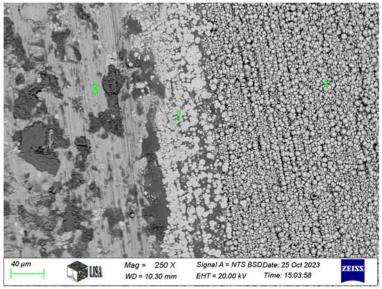
Figure 13.
Wear track of the Ni-B coating.
Studies by Ahmed et al. [23] and Tohidi et al. [40] also found that Ni-P coatings generally exhibited better wear resistance compared to Ni-B coatings. The use of Ni-P as an intermediate layer in duplex coatings improved the overall wear resistance.
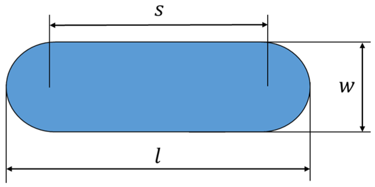
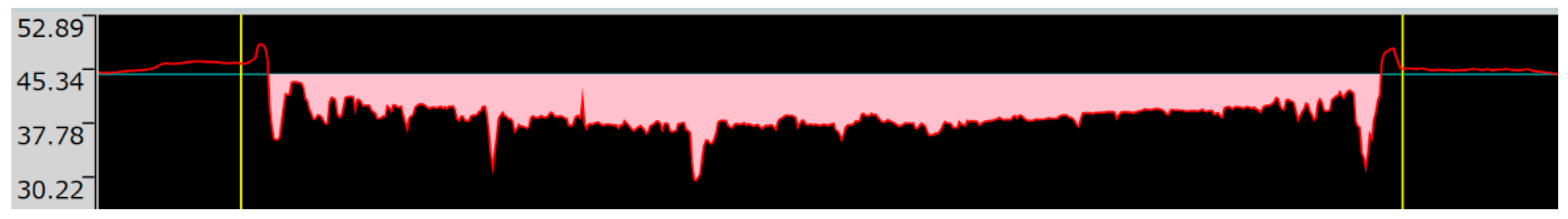
The volume of wear loss was measured by using an Olympus DSX1000 digital measuring microscope (Olympus, Tokyo, Japan). The interpretation of the width and length of the wear mark is illustrated in Figure 14, where is the wear mark length [mm], w is the wear mark width [mm], and s is the amplitude of the oscillating measurement [mm].
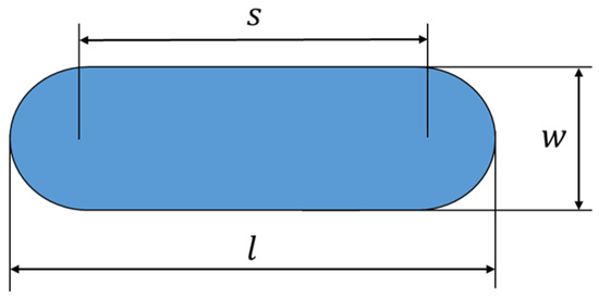
Figure 14.
Notation of the width and length of a wear mark.
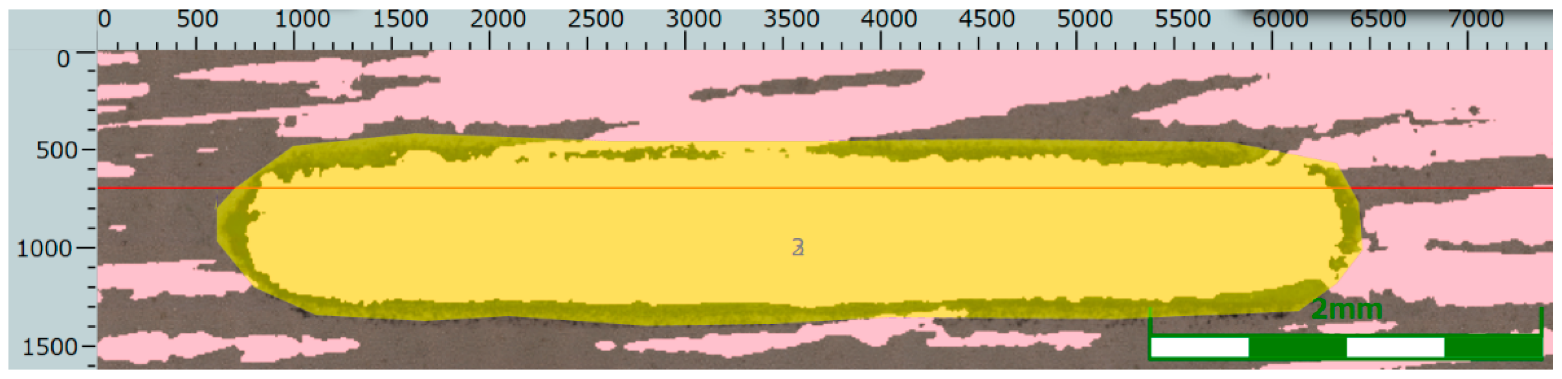
The determination of the wear volume loss on the wear cross-section is shown in Figure 15, Figure 16 and Figure 17.
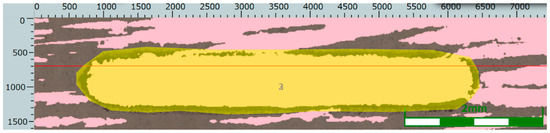
Figure 15.
Wear track and a straight line parallel to the wear track in the case of the Ni-B specimen.
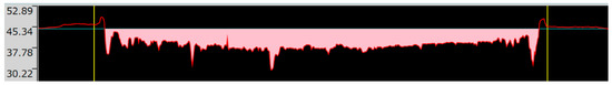
Figure 16.
Wear cross-section along the straight line drawn parallel to the wear track in the case of the Ni-B specimen.
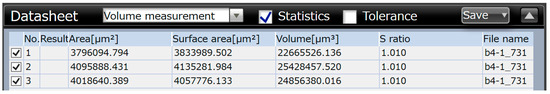
Figure 17.
Wear volume loss based on the wear cross-section in the case of the Ni-B specimen.
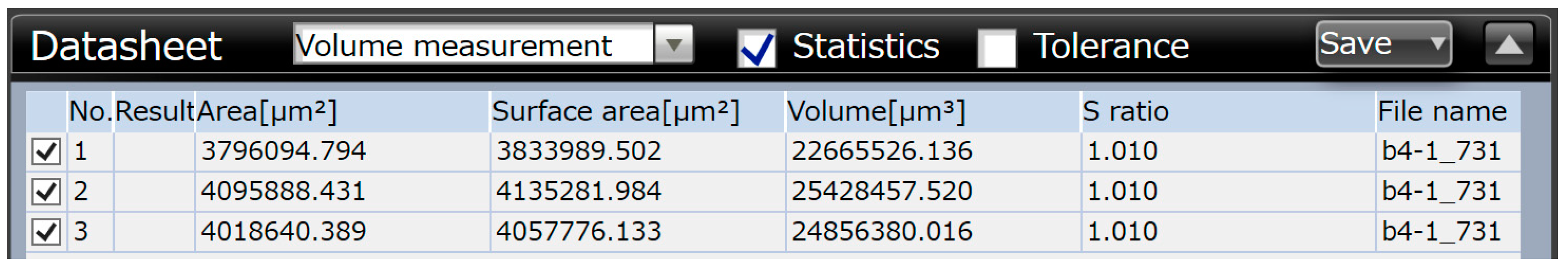
The average values of wear volume based on the microscopic measurements are summarized in Table 9.
Table 9.
Results of microscopic measurements of wear volume.
In Table 9, WSP is the wear volume loss measured by the Olympus DSX1000 digital measuring microscope, w is the width of the wear track, and l is the length of the wear track. Based on the results of Table 9, the Ni-P-I coating has the lowest wear volume loss, while the Ni-B coating has the highest wear volume loss.
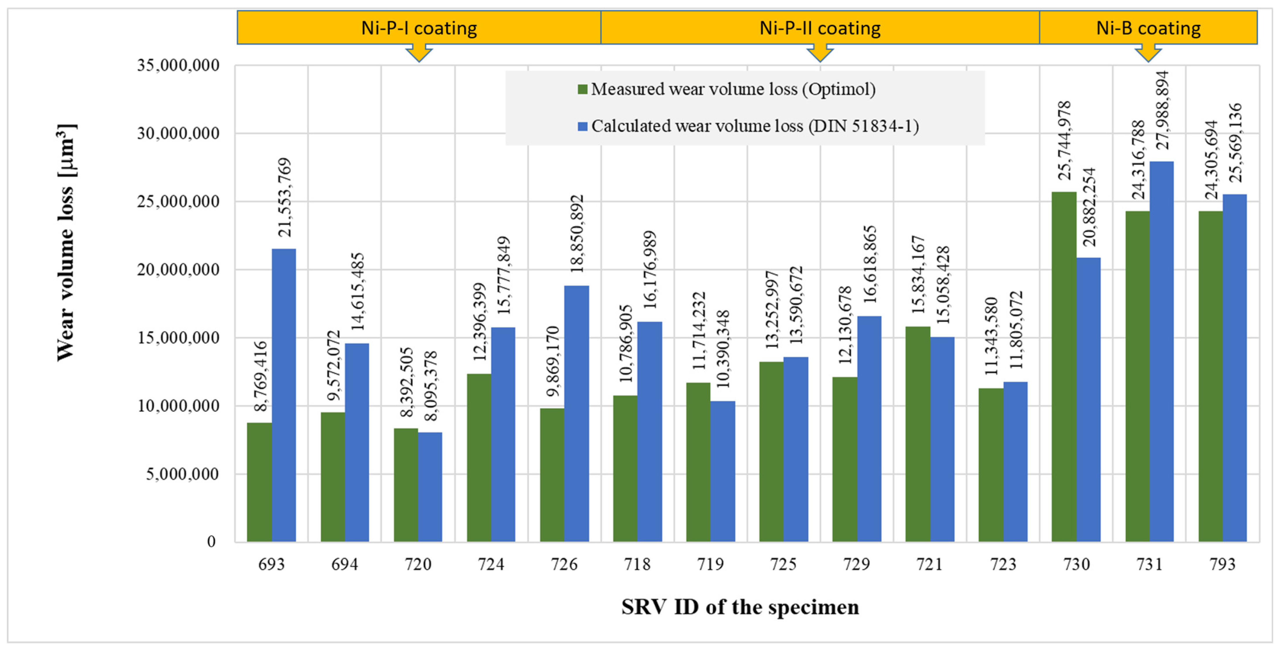
The value of wear volume loss calculated according to DIN 51834-1 was 81–246% of the corresponding measured value of wear volume loss (see Figure 18). No clear relationship can be established between the measured value and the calculation result according to DIN 51834-1, since in some cases, the calculated value was lower, and in other cases, the measured value was lower. Various parameters can influence the difference between the calculated and measured values, e.g., the way the specimen is fixed on the specimen holder, or the specimen is not parallel to the plane of the alternating movement of the counter-body.
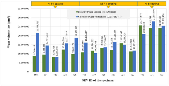
Figure 18.
Comparison of measured and calculated wear volume loss.
3.5. Wear Coefficients
The wear coefficients can then be determined according to Archard’s and Liu’s models. The Archard’s wear coefficient is calculated as follows [37]
where is the measured wear volume loss of the specimen , is the load force [N], is the Vickers microhardness of the coating, and is the length of the wearing route taken by the counter-body [m].
The total route of the counter-body can be determined as follows
where is the frequency of the counter-body movement [Hz], is the amplitude of the counter-body’s path, and is the time span of the wear test [s]. The wear coefficients based on Archard’s model are summarized in Table 10.
Table 10.
Calculation of average wear coefficient based on Archard’s model for L = 1.8 × 108 μm and FN = 15 N.
Liu’s wear coefficient considers a different approach to the determination of the contact area between the specimen and the counter-body [38]
where h is the depth of the wear track. The calculated values of Liu’s dimensionless wear coefficients with the measured values of are summarized in Table 11. The Liu’s wear coefficient was determined with = 1800 s.
Table 11.
The average wear coefficients are based on Liu’s model.
Based on the calculation of Archard’s and Liu’s wear coefficients, it can be concluded that the two wear coefficients are very similar, with a multiplier of 2–3; the highest wear coefficient has been detected for both calculation methods for Ni-B. Note that for all coatings, the Archard’s wear coefficient was higher than Liu’s.
4. Conclusions
This study thoroughly analyzes the surface and tribological properties of electroless Ni-P and Ni-B coatings. The Ni-P-I coating, characterized by its blackberry-like morphology, exhibited the highest microhardness (543 HV 0.01). In contrast, the Ni-B coating, with a pebble-like structure, showed the lowest microhardness (429 HV 0.01). The Ni-P-II coating, with a cauliflower-like morphology, demonstrated the lowest coefficient of friction (average COF of 0.8408), making it the most promising candidate for applications requiring low-friction surfaces.
Wear analysis revealed that the Ni-B coating had the highest wear volume loss, approximately 1.5 times greater than the Ni-P coatings. Both Archard’s and Liu’s wear coefficients indicated similar trends, with the Ni-B coating exhibiting the highest wear coefficient. The Ni-P-II coating performed best overall due to its low friction coefficient and competitive wear resistance.
These findings highlight the importance of selecting appropriate coatings based on specific application requirements. For instance, the Ni-P-II coating’s high friction and moderate wear resistance make it suitable for applications such as brake linings, where both properties are critical. Future research should focus on optimizing the deposition parameters and exploring composite coatings to further enhance the performance of electroless Ni-P and Ni-B coatings.
Author Contributions
Methodology, K.B., M.C., S.K. and G.B.; Validation, G.B.; Investigation, K.B., M.C. and S.K.; Data curation, K.B.; Writing—original draft, M.C., S.K. and G.B. All authors have read and agreed to the published version of the manuscript.
Funding
This research received no external funding.
Data Availability Statement
The raw data supporting the conclusions of this article will be made available by the authors on request.
Acknowledgments
The authors were supported by project no. 129257 implemented with the support provided to the corresponding author from the National Research, Development and Innovation Fund of Hungary, financed under the K18 funding scheme.
Conflicts of Interest
Author Sándor Kovács was employed by the company Bay Zoltán Nonprofit, Ltd. The remaining authors declare that the research was conducted in the absence of any commercial or financial relationships that could be construed as a potential conflict of interest.
References
- Li, J.; Yan, H.; Li, S.; Lei, M. Microstructure and wear behavior of arc-shaped 40CrNiMo steel after laser hardening. J. Mater. Res. Technol. 2023, 24, 5743–5754. [Google Scholar] [CrossRef]
- Lee, M.K.; Kim, G.H.; Kim, K.H.; Kim, W.W. Effects of the surface temperature and cooling rate on the residual stresses in a flame hardening of 12Cr steel. J. Mater. Process. Technol. 2006, 176, 140–145. [Google Scholar] [CrossRef]
- Chen, W.; He, X.; Yu, W.; Wang, M.; Yao, K. Microstructure, Hardness, and Tensile Properties of Vacuum Carburizing Gear Steel. Metals 2021, 11, 300. [Google Scholar] [CrossRef]
- Casteletti, L.C.; Neto, A.L.; Totten, G.E. Nitriding of Stainless Steels. Metallogr. Microstruct. Anal. 2014, 3, 477–508. [Google Scholar] [CrossRef]
- Fotovvati, B.; Namdari, N.; Dehghanghadikolaei, A. On Coating Techniques for Surface Protection: A Review. JMMP 2019, 3, 28. [Google Scholar] [CrossRef]
- Czagány, M.; Varanasi, D.; Sycheva, A.; Janovszky, D.; Koncz-Horváth, D.; Kristaly, F.; Baumli, P.; Kaptay, G. Synthesis, characterisation and thermal behaviour of Cu-based nano-multilayer. J. Mater. Sci. 2021, 56, 7823–7839. [Google Scholar] [CrossRef]
- He, Q.; Paiva, J.M.; Kohlscheen, J.; Beake, B.D.; Veldhuis, S.C. An integrative approach to coating/carbide substrate design of CVD and PVD coated cutting tools during the machining of austenitic stainless steel. Ceram. Int. 2020, 46, 5149–5158. [Google Scholar] [CrossRef]
- Xie, Y.; Liu, J.; Liu, W.; Li, Q.; Feng, W.; Yang, L.; Zhou, Y. Performance and failure modes of thermal barrier coatings deposited by EB-PVD on blades under real service conditions in gas turbine. J. Alloys Compd. 2024, 1008, 176889. [Google Scholar] [CrossRef]
- Siwawut, S.; Srikhumsuk, P.; Butdee, S. Tool life and wear prediction of HSS and PVD material using ANFIS system. Mater. Today Proc. 2023, S2214785323048538. [Google Scholar] [CrossRef]
- Vasu, C.; Andhare, A.B.; Dumpala, R. Machinability and tool wear studies on AZ91/B4C metal matrix composites using uncoated and CVD diamond coated WC-Co turning inserts. Int. J. Refract. Met. Hard Mater. 2024, 119, 106538. [Google Scholar] [CrossRef]
- Larson, C.; Smith, J.R. Recent trends in metal alloy electrolytic and electroless plating research: A review. Trans. IMF 2011, 89, 333–341. [Google Scholar] [CrossRef]
- Agarwala, R.C.; Agarwala, V.; Sharma, R. Electroless Ni-P Based Nanocoating Technology—A Review. Synth. React. Inorg. Met.-Org. Nano-Met. Chem. 2006, 36, 493–515. [Google Scholar] [CrossRef]
- Shakoor, R.A.; Kahraman, R.; Gao, W.; Wang, Y. Synthesis, Characterization and Applications of Electroless Ni-B Coatings—A review. Int. J. Electrochem. Sci. 2016, 11, 2486–2512. [Google Scholar] [CrossRef]
- Barati, Q.; Hadavi, S.M.M. Electroless Ni-B and composite coatings: A critical review on formation mechanism, properties, applications and future trends. Surf. Interfaces 2020, 21, 100702. [Google Scholar] [CrossRef]
- Kumar, S.; Banerjee, T.; Patel, D. Tribological characteristics of electroless multilayer coating: A review. Mater. Today Proc. 2020, 33, 5678–5682. [Google Scholar] [CrossRef]
- Gyökér, Z.; Gergely, G.; Takáts, V.; Gácsi, Z. Machine learning-assisted characterization of electroless deposited Ni–P particles on nano/micro SiC particles. Ceram. Int. 2023, 49, 29849–29856. [Google Scholar] [CrossRef]
- Sudagar, J.; Lian, J.; Sha, W. Electroless nickel, alloy, composite and nano coatings—A critical review. J. Alloys Compd. 2013, 571, 183–204. [Google Scholar] [CrossRef]
- Czagany, M.; Baumli, P. Effect of pH on the characteristics of electroless Ni-P coatings. J. Min. Met. B Met. 2017, 53, 327–332. [Google Scholar] [CrossRef]
- Umapathi, D.; Devaraju, A.; Rathinasuriyan, C.; Raji, A. Mechanical and tribological properties of electroless nickel phosphorous and nickel Phosphorous-Titanium nitride coating. Mater. Today Proc. 2020, 22, 1038–1042. [Google Scholar] [CrossRef]
- Solimani, A.; Meißner, T.M.; Oskay, C.; Galetz, M.C. Electroless Ni–P coatings on low-Cr steels: A cost-efficient solution for solar thermal applications. Sol. Energy Mater. Sol. Cells 2021, 231, 111312. [Google Scholar] [CrossRef]
- Vitry, V.; Hastir, J.; Mégret, A.; Yazdani, S.; Yunacti, M.; Bonin, L. Recent advances in electroless nickel-boron coatings. Surf. Coat. Technol. 2022, 429, 127937. [Google Scholar] [CrossRef]
- Yazdani, S.; Vitry, V. RSM models approach for optimization of the mechanical properties of electroless Ni-B-nanodiamond coating: An experimental and molecular dynamic simulation study. Surf. Coat. Technol. 2023, 452, 129133. [Google Scholar] [CrossRef]
- Ahmed, S.Y.; Mahmoud, S.B.; Shoeib, M.A. Synthesis, structure characterization, and corrosion properties of duplex electroless Ni-P/Ni-B and Ni-P/Ni-BW coatings on mild steel. Sci. Rep. 2024, 14, 24983. [Google Scholar] [CrossRef]
- Loto, C.A. Electroless Nickel Plating—A Review. Silicon 2016, 8, 177–186. [Google Scholar] [CrossRef]
- Czagány, M.; Baumli, P. Effect of surfactants on the behavior of the Ni-P bath and on the formation of electroless Ni-P-TiC composite coatings. Surf. Coat. Technol. 2019, 361, 42–49. [Google Scholar] [CrossRef]
- Balaraju, J.N.; Narayanan, T.S.N.S.; Seshadri, S.K. Electroless Ni–P composite coatings. J. Appl. Electrochem. 2003, 33, 807–816. [Google Scholar] [CrossRef]
- Czagany, M.; Hompoth, S.; Windisch, M.; Baumli, P. Investigation of the Supercapacitive Behavior of Electroless Ni-B Coatings. Metals 2023, 13, 1233. [Google Scholar] [CrossRef]
- Erdemir, F.; Güler, O.; Çanakçı, A. Electroless nickel-phosphorus coated expanded graphite paper: Binder-free, ultra-thin, and low-cost electrodes for high-performance supercapacitors. J. Energy Storage 2021, 44, 103364. [Google Scholar] [CrossRef]
- Sharma, P.J.; Modi, K.H.; Sahatiya, P.; Sumesh, C.K.; Pataniya, P.M. Electroless deposited NiP-fabric electrodes for efficient water and urea electrolysis for hydrogen production at industrial scale. Appl. Surf. Sci. 2024, 644, 158766. [Google Scholar] [CrossRef]
- Delaunois, F.; Vitry, V.; Bonin, L. (Eds.) Electroless Nickel Plating: Fundamentals to Applications, 1st ed.; CRC Press: Boca Raton, FL, USA, 2019. [Google Scholar] [CrossRef]
- Czagány, M.; Baumli, P.; Kaptay, G. The influence of the phosphorous content and heat treatment on the nano-micro-structure, thickness and micro-hardness of electroless Ni-P coatings on steel. Appl. Surf. Sci. 2017, 423, 160–169. [Google Scholar] [CrossRef]
- Krishnan, K.H.; John, S.; Srinivasan, K.N.; Praveen, J.; Ganesan, M.; Kavimani, P.M. An overall aspect of electroless Ni-P depositions—A review article. Met. Mater. Trans. A 2006, 37, 1917–1926. [Google Scholar] [CrossRef]
- Wang, P.; Liang, H.; Jiang, L.; Qian, L. Effect of nanoscale surface roughness on sliding friction and wear in mixed lubrication. Wear 2023, 530, 204995. [Google Scholar] [CrossRef]
- Park, J.Y.; Salmeron, M. Fundamental aspects of energy dissipation in friction. Chem. Rev. 2014, 114, 677–711. Available online: https://pubs.acs.org/doi/10.1021/cr200431y (accessed on 7 February 2024).
- Khaday, S.; Li, K.W.; Peng, L.; Chen, C.C. Relationship between friction coefficient and surface roughness of stone and ceramic floors. Coatings 2021, 11, 1254. [Google Scholar] [CrossRef]
- DIN 51834-1; Testing of Lubricants—Tribological Test in the Translatory Oscillation Apparatus—Part 1: General Working Principles. Deutsches Institut Fur Normung: Berlin, Germany, 2010.
- Ravikiran, A. Wear Quantification. J. Tribol. 2000, 122, 650–656. [Google Scholar] [CrossRef]
- Liu, T.; Yu, J.; Wang, H.; Yu, Y.; Li, H.; Zhou, B. Modified method for determination of wear coefficient of reciprocating sliding wear and experimental comparative study. J. Mar. Sci. Eng. 2022, 10, 1014. [Google Scholar] [CrossRef]
- Bulbul, F. The effects of deposition parameters on surface morphology and crystallographic orientation of electroless Ni-B coatings. Met. Mater. Int. 2011, 17, 67–75. [Google Scholar] [CrossRef]
- Tohidi, A.; Monirvaghefi, S.M.; Hadipour, A. Properties of electroless Ni–B and Ni–P/Ni–B coatings formed on stainless steel. Trans. Indian. Inst. Met. 2017, 70, 1735–1742. [Google Scholar] [CrossRef]
- ISO 6507-1:2023; Metallic Materials—Vickers Hardness Test—Part 1: Test Method. ISO: Geneva, Switzerland, 2023. Available online: https://www.iso.org/obp/ui/fr/#iso:std:iso:6507:-1:ed-5:v1:en (accessed on 6 February 2024).
- Fritsch: Mini Mill Pulverisette 23—Grinding Balls. Available online: https://www.fritsch-international.com/sample-preparation/milling/ball-mills/details/product/pulverisette-23/accessories/ (accessed on 7 February 2024).


Disclaimer/Publisher’s Note: The statements, opinions and data contained in all publications are solely those of the individual author(s) and contributor(s) and not of MDPI and/or the editor(s). MDPI and/or the editor(s) disclaim responsibility for any injury to people or property resulting from any ideas, methods, instructions or products referred to in the content. |
© 2025 by the authors. Licensee MDPI, Basel, Switzerland. This article is an open access article distributed under the terms and conditions of the Creative Commons Attribution (CC BY) license (https://creativecommons.org/licenses/by/4.0/).