Article

Research on Feature Extraction Method and Process Optimization of Rolling Bearing Faults Based on Electrostatic Monitoring

1
School of Automobile and Traffic Engineering, Jiangsu University of Technology, Changzhou 213001, China
2
College of Civil Aviation, Nanjing University of Aeronautics and Astronautics, Nanjing 211106, China
*
Author to whom correspondence should be addressed.
Lubricants 2025, 13(4), 178; https://doi.org/10.3390/lubricants13040178
Submission received: 5 March 2025 / Revised: 10 April 2025 / Accepted: 10 April 2025 / Published: 12 April 2025

Abstract

:
Electrostatic detection is a highly accurate way to monitor system performance failures at an early stage. However, due to the weak electrostatic signal, it can be easily interfered with under complex real-world conditions, leading to a reduction in its monitoring capability. During the electrostatic monitoring of rolling bearings, noise can easily drown out the effective signal, making it difficult to extract fault characteristics. In order to solve this problem, a sparse representation based on cluster-contraction stagewise orthogonal matching pursuit (CcStOMP) is proposed to extract the fault features in the electrostatic signals of rolling bearings. The method adds a clustering contraction mechanism to the stagewise orthogonal matching pursuit (StOMP) algorithm, performs secondary filtering based on atom similarity clustering on the selected atoms in the atom search process, updates the support set, and finally solves the weights and updates the residuals, so as to reconstruct the original electrostatic signals and extract the fault feature components of rolling bearings. The method maintains fast convergence while analysing the extraction effect by comparing the measured signals of rolling bearing outer ring and bearing roller faults with the traditional StOMP algorithm, and the results show that the CcStOMP algorithm has obvious advantages in accurately extracting the fault features in the electrostatic monitoring signals of rolling bearings.

1. Introduction

Rolling bearings are widely used in all kinds of rotating machinery, and they are the most common parts in many kinds of key rotating machinery and equipment, such as engines, wind generators, motors, and so on [1,2,3,4]. In the process of equipment operation, rolling bearings are prone to failure due to high rotational speeds, large loads, and other reasons such as environmental complexity. According to relevant statistics, 70% of the failures of rotating machinery and equipment are related to bearings and gears [5], so fault diagnosis of rolling bearings is an indispensable part of the maintenance of rotating machinery and equipment. At present, the traditional means of rolling bearing fault monitoring is mainly vibration monitoring. In the process of equipment operation, the rolling bearing, due to its periodic rotation characteristics, whenever passing through the load area, will produce corresponding periodic vibration signals, and these vibration signals are in the rolling bearing are captured by vibration sensors, processed, and analysed. Due to the operation process, there will inevitably occur a specific frequency of vibration impact, so vibration monitoring is currently the most mainstream and one of the most effective monitoring methods. Therefore, vibration monitoring is a relatively mature fault monitoring technology. For early bearing fault diagnosis, the traditional internal sensing accelerometer used for vibration measurement has a poor signal-to-noise ratio, which increases the difficulty and complexity of early fault diagnosis. In response to this situation, Wang et al. [6] developed a wireless three-axis on-rotor sensing (ORS) system, which substantially improves the signal-to-noise ratio, and used fast Fourier transform (FFT) and Hilbert envelope analysis for accurate diagnosis of early rolling bearing faults, substantially improving the accuracy and efficiency of early fault diagnosis. The vibration characteristics of rotating machinery are crucial for determining the rotational frequency and fault frequency. The traditional contact measurement method has some limitations; therefore, to address this problem, Li et al. [7] proposed a vision-based rotating machinery vibration feature extraction method to analyse the fault frequency by extracting the small vibration of the bearing.
However, the vibration signal requires mechanical deformation to accumulate to a certain magnitude before it can be effectively captured, and it cannot detect microscopic wear. Therefore, this study proposes a non-contact monitoring method based on electrostatic sensing. The electrostatic monitoring technique utilises the wear region charging mechanism to inductively detect the charge level at the location of the defect and is not interfered with by the working conditions of the moving parts [8]. Tian et al. [9] investigated the wear process surface charge evolution, its interaction with friction, and the correlation between charge distribution and surface chemistry. Harvey et al. examined the correlation between wear debris charging and wear rate using charge level measurements and explored the effect of lubricant quality on frictional charging, with an emphasis on the charge-carrying currents that exist within the lubricant [10,11,12]. Compared to traditional vibration monitoring, electrostatic monitoring avoids direct contact coupling to other vibration sources and provides a more intuitive indication of wear at the fault location. Electrostatic monitoring was first applied to aerospace engines to monitor airway faults such as abrasion and contact wear. Zhang et al. [13] investigated the electrostatic monitoring of bearing steel initial failure by means of a pin-on disc wear test bench.
During signal acquisition, the charge signal exhibits a variety of characteristics including the presence of the target signal (transient pulse peaks), noise, baseline drift, and overlapping peaks, which makes it difficult to extract the charge distribution in the particle population. Therefore, a signal processing method is needed to reduce the noise level, thereby improving the signal-to-noise ratio, detecting peaks (positive and/or negative), and providing the boost distribution data needed to understand the complex phenomenon of turbocharging. The common signal processing methods for rolling bearing fault diagnosis are wavelet packet decomposition [14] and EEMD [15], but the wavelet packet decomposition algorithm is strongly influenced by the degree of decomposition, while the immunity of the EEMD algorithm is strongly influenced by the white noise amplitude coefficients and the overall averaging times, among others. For diagnosing early bearing defects, Vishal G. Salunkhe et al. proposed a deep independent component analysis (VMD-ICA) [16] method based on variational modal decomposition, and they investigated the feasibility of combining a deep independent component analysis (ICA) method based on variational modal decomposition (VMD) with a one-dimensional convolutional neural network (1D-CNN) to diagnose early bearing defects [17]. Sparse representation (SR) [18] is a novel signal processing method that uses sparse decomposition to represent the original signal as a linear combination of a small number of atoms. It is mainly divided into two parts: the dictionary construction method and the sparse recovery algorithm. Compared with other signal processing methods, SR is able to extract and reconstruct the fault feature components from the original signal, thus effectively extracting the fault signal from the noise. In recent years, sparse representation theory has attracted the attention of scholars. Zheng et al. [19] proposed a composite fault diagnosis method for bearings by combining the cascaded overcomplete dictionary with the feature symbol search algorithm. Sun R B et al. [20] used a structured sparse time–frequency analysis method for gear fault diagnosis. Deng et al. [21] used a sparse representation based on orthogonal matching pursuit (OMP) for the purpose of feature extraction of the vibration characteristics of bearing coupling faults. He G. L. et al. [22] completed SR-based feature extraction of rolling bearing faults.
The main contributions of this study are as follows: (1) a rare rolling bearing fault diagnosis method is proposed, namely electrostatic monitoring, which has higher sensitivity than traditional vibration monitoring and can monitor the occurrence of system performance degradation earlier; (2) for the characteristics of rolling bearing electrostatic monitoring technology, the original transient fault features are signal reconstructed using a sparse recovery algorithm, and the fault feature components are extracted; and (3) a CcStOMP [18] algorithm is proposed, optimised on the basis of StOMP [23] and adding a clustering contraction mechanism on the basis of the original algorithm, making the algorithm more advantageous in fault feature recognition accuracy.

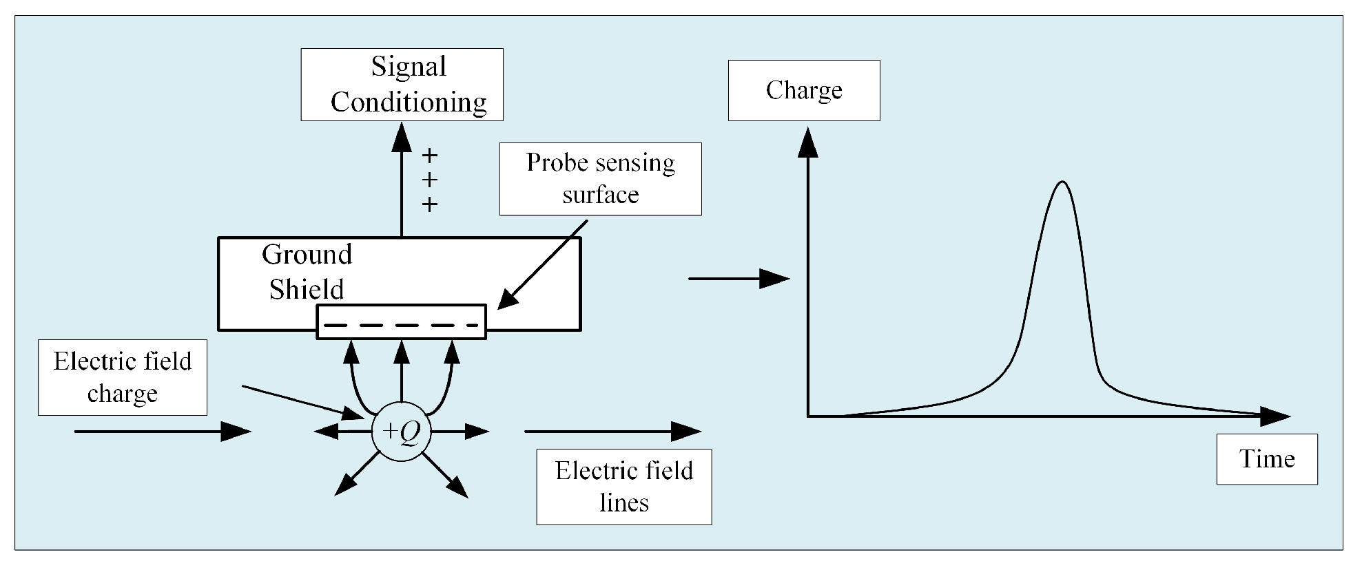
2. Principle of Electrostatic Monitoring

Electrostatic monitoring technology is a condition monitoring technology for charged particles in the wear region of rolling bearings. When the charged particles pass between the friction sub-surfaces of the electrostatic sensor’s probe sensing surface, the electric field generated by the charges terminates at the probe’s surface. Through electrostatic induction, charge redistribution occurs: free electrons within the probe migrate toward or away from the sensing surface depending on the polarity of the external charges. This movement generates an induced current, with positive charges flowing opposite to electrons, creating a measurable signal correlated with wear severity.
During the electrostatic induction process, the end of the sensor is connected to a signal conditioning unit that converts the induced charge in real time into an electrostatically induced voltage signal that can be measured and studied, thus enabling electrostatic monitoring of the wear area. When the wear of a mechanical part increases, the charge of the charged abrasive particles around the friction pair increases dramatically. Therefore, the wear of mechanical parts can be monitored in real time by means of electrostatic sensors. The principle of electrostatic monitoring is shown in Figure 1.
In the electrostatic monitoring of rolling bearing wear regions, the charge induced on the electrostatic probe sensing surface is denoted as Q ( t ) , the voltage signal measured by the acquisition system is denoted as U ( t ) , and the default initial state of the system is 0. The charge Q ( t ) and the voltage U ( t ) are Laplace-transformed to Q ( s ) , and U ( s ) , respectively, and they satisfy the following equation:
U ( s ) = R s Q ( s ) / ( R C s + 1 )
In this formula, R represents the equivalent resistance of the detection circuit; s denotes the complex frequency variable in the Laplace domain; and C is the equivalent capacitance of the circuit.
When R C s 1 , the electrostatic signal monitoring model can be equated as
U ( t ) = R d Q d t
Therefore, the raw voltage signal U ( t ) collected by the bearing acquisition system is directly proportional to the first order derivative of the charge Q ( t ) on the inductive surface of the electrostatic sensor, indicating that the electrostatic level is a visual response to the degree of rolling bearing failure.

3. Sparse Representation Theory

3.1. Sparse Representation Model

Sparse representation is a mathematical framework that achieves signal compression by optimally selecting and weighting atoms from a predefined dictionary. This methodology comprises two fundamental components: dictionary design and sparse signal recovery algorithms. Assuming that the original electrostatic signal is a vector set y π A , whose vector expansion is y = y 1 , y 2 , y 3 , y A , if there exists an overwhelming majority of elements of the vector set satisfying y i = 0 , then the vector y can be a sparse vector. If there exists a transformation matrix B π A × K , whose vector expansion B = b 1 , b 2 , b 3 , , b K satisfies the condition that the π matrix column factor is larger than row factor, and π A is a full rank matrix, then the original electrostatic signal can be defined as an underdetermined linear equation:
y = B d + γ
In this formula, d = d 1 , d 2 , d 3 , , d K T π K is the sparse vector; and γ is the residual signal.
If the solution vector of a sparse vector d has e non-zero elements and satisfies e K , then the sparsity of the vector d is e . From Equation (3), the solution vector d has a number of sets of solutions, which introduces sparsity constraints, so the objective function d of the sparse solution is
d = argmin d d q   s . t .   B d = y
d q = i = 1 K d i q 1 / q
In these formulas, d q is the number of paradigms for l q .
Sparse recovery algorithms are mainly based on the conditions of sparse problems with two paradigms, l 0 and l 1 . For l 0 -paradigm sparse solutions, the minimisation of the l 0 paradigm is mathematically a nondeterministic polynomial; for l 1 -paradigm sparse problems, convex optimal algorithms are often used, but the minimisation of the l 1 paradigm may dramatically reduce the sparsity of the solution. Based on the l 0 -paradigm constraints on the sparse representation with the objective function,
d = argmin d d 0 s t B d = y

3.2. Parse Dictionary Construction

From Section 3.1, it can be seen that the dense electrostatic signal is transformed into sparse vectors through the transform matrix B, and the dictionary B is the basic element for defining the sparse domain. The fault signal of the rolling bearing is a discrete non-stationary signal, and the signal is divided into the fault instantaneous shock characteristic component x and random noise f. The rolling bearing shock response model y is expressed as follows:
y = x + f
There are two main types of constructed dictionaries: parsed dictionaries and learning dictionaries. Parsed dictionaries are fast to solve, and since sparse representation objects have high directionality, parsed dictionaries are chosen to construct parsed dictionaries. Bearing fault diagnosis requires a clear identification of fault characteristics, and the rolling bearing operating process involves a shock response with shock attenuation characteristics. The Laplace wavelet can effectively extract the fault feature components, so this paper adopts it for the atomic construction of the analytic dictionary. The Laplace wavelet dictionary mathematical expression is as follows:
ψ ( t , f , ζ , τ ) = e x p ζ 1 ζ 2 2 π f ( t τ ) s i n 2 π f ( t τ ) t [ τ , τ + W m ] 0 e l s e
In this formula, f is the oscillation frequency; ζ is the damping ratio; τ is the time scale; and W m is the dictionary support interval.
In order that the sparse signal fault characteristics can be more prominent, the parameters in the wavelet dictionary need to be constrained. From the signal instantaneous shock pattern parameter valuation f ˜ and ζ ˜ , the parameters are set as follows:
| ζ ζ ˜ | η | f f ˜ | η τ ( 0 , N )
In this formula, η is a very small positive number.

3.3. Sparse Recovery Algorithm

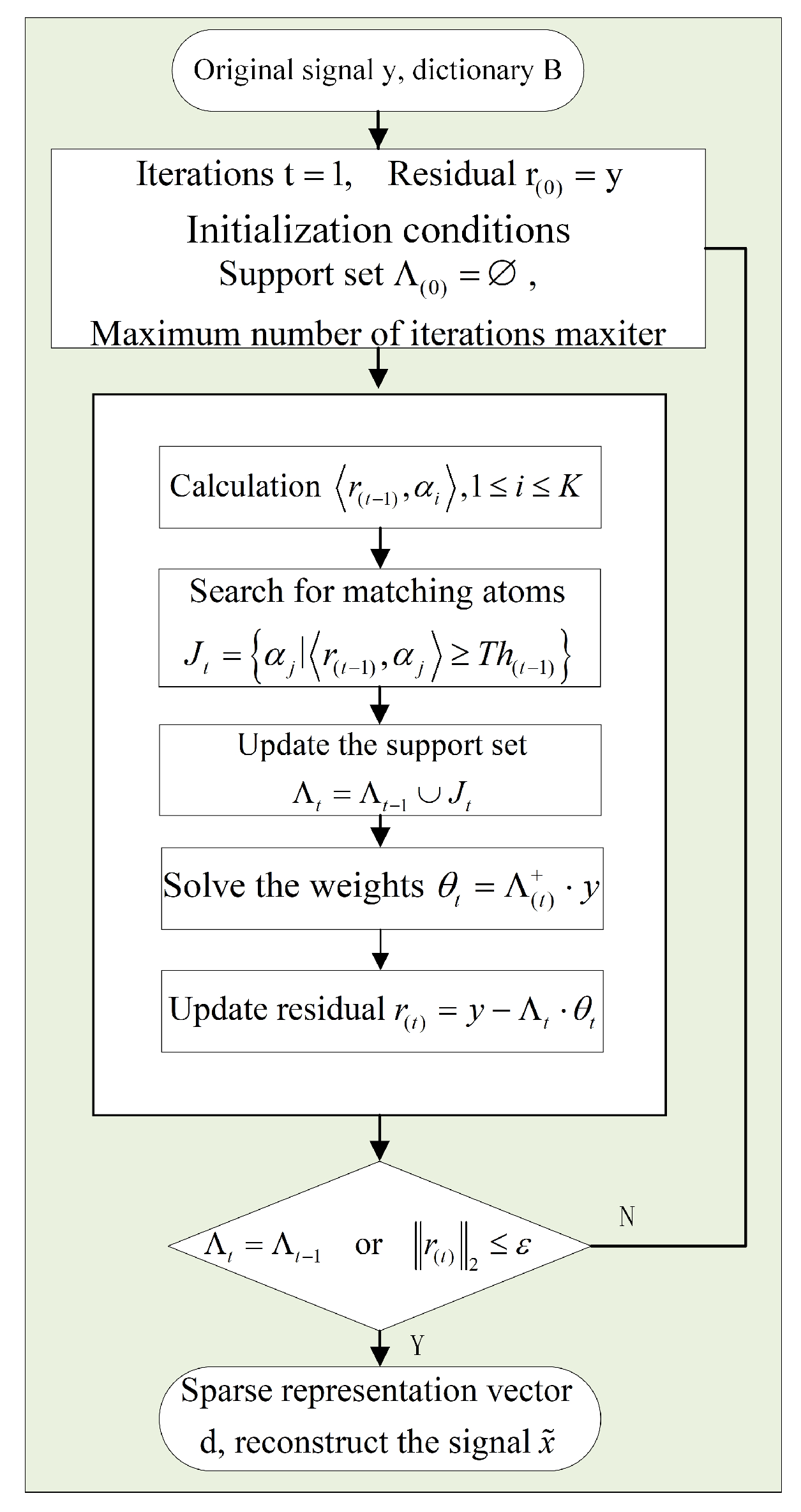
3.3.1. StOMP Algorithm

In 2012, Donoho D. et al. [24] combined the orthogonal matched tracking algorithm with least-angle regression (LAR) [25], and subsequently proposed the segmented orthogonal matched tracking algorithm (StOMP). Based on the l 0 -parameter constraints for the sparse optimisation problem, and due to the presence of background noise in the signal, random pulses, and other effects of the original bearing electrostatic signal, the Equation (6) is rewritten as follows:
argmin d 0   s . t . y B d δ
In this formula, δ is a small positive number and is used to measure the noise level.
The StOMP algorithm mainly improves the method of updating the support set, which is defined by setting a threshold criterion instead of a maximisation criterion. The threshold criterion is defined as follows:
T h t = t s r ( t 1 ) 2 N
In this formula, r ( t 1 ) is the residual value after t 1 iterations; t s is the scale factor; and t s 0 , 1 .
If an appropriate threshold is set, atoms in the support set can match more candidate atoms in a single iteration. This enhancement accelerates the atom matching process, which ultimately improves the computational efficiency of the StOMP algorithm when solving for optimal solutions.
The core of the StOMP algorithm is to calculate the inner product of matching atoms and residuals in the parsing dictionary to solve the correlation, and then preset the threshold, screen out all matching atoms with correlations greater than the threshold, update them to the support set Λ t , again find the weights θ t by the least squares method, and finally iteratively calculate the optimal solution for the reconstruction of this group of electrostatic signals. The solution process of the StOMP algorithm is shown in Figure 2.
The main advantage of electrostatic monitoring is its ability to detect early bearing damage within the rolling contact area. However, in actual implementation, this technology is susceptible to industrial frequency noise, bearing cage frequency components, and random pulse interference, which often mask early bearing fault characteristics and reduce the detection accuracy of characteristic fault components processed by the StOMP algorithm.

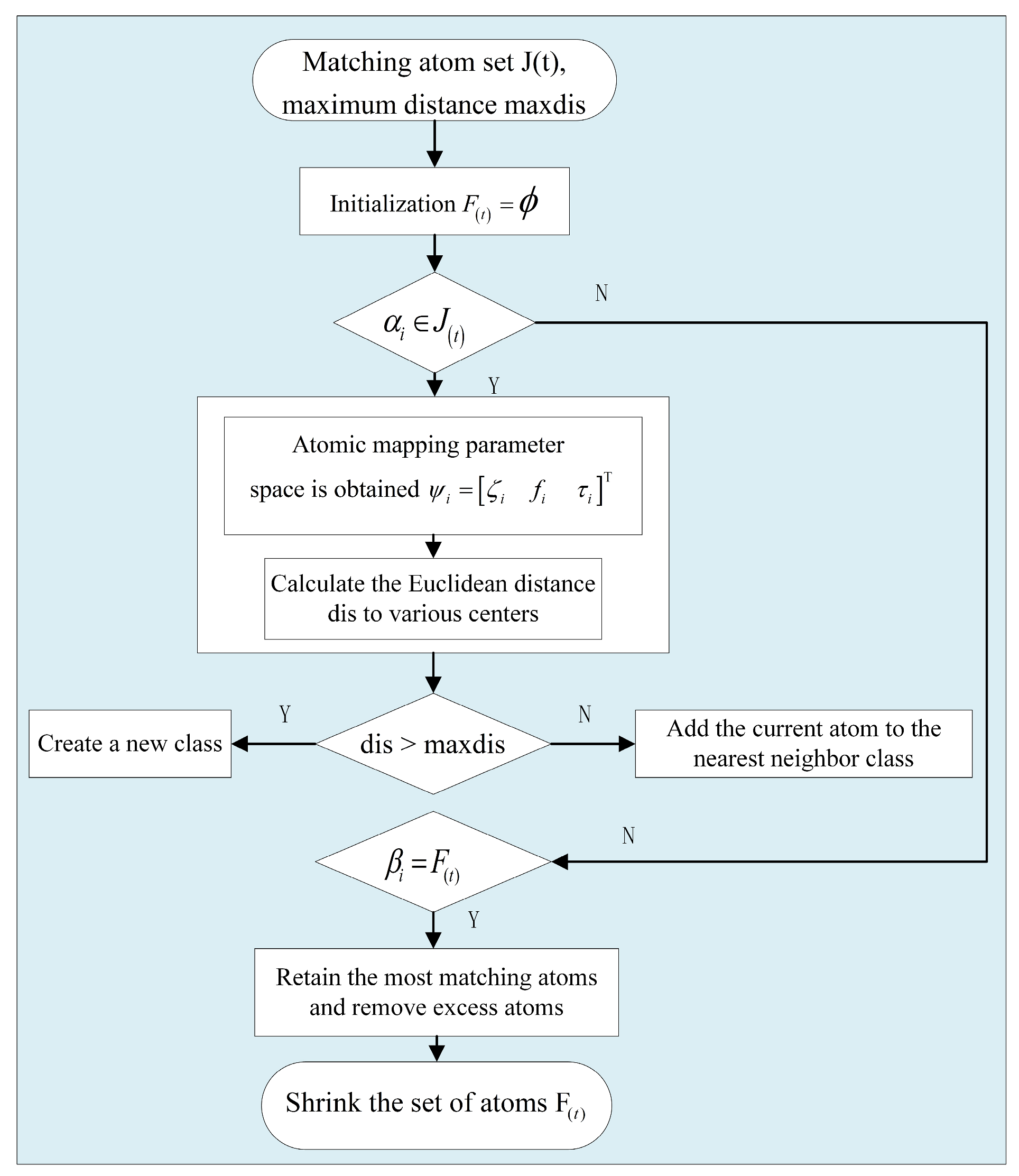
3.3.2. CcStOMP Algorithm

The CcStOMP algorithm is optimised on the basis of StOMP. The CcStOMP algorithm increases the clustering contraction mechanism in the StOMP algorithm and filters the atoms to be selected twice in the atom searching process, which makes CcStOMP more advantageous in fault feature recognition accuracy. In order to improve the sparse accuracy, a clustering contraction mechanism is proposed, using the k-nearest neighbour algorithm to remove the redundant atoms inside the support set. The core idea is to map the atoms to the parameter space to obtain ψ i , and then the used signal atoms are clustered using k-nearest neighbours to retain the best-matching atoms while removing the redundant atoms. The principle of the clustering shrinkage mechanism is shown in Figure 3.
In the clustering contraction algorithm based on the search atoms for secondary filtering, redundant atoms can ultimately be completely eliminated in the support set. From Equation (9), the matching atoms in the wavelet dictionary are identified through the valuation of each parameter to carry out the expansion of the neighbourhood, and these atoms form the parameter space that is s p a n ζ , f , τ . Considering that the bearing fault feature components are discrete, the threshold criterion for the carrying out of the atomic search means several similar atoms may be screened together. Therefore, considering the iterative intermediate process support set, the function is as follows:
Λ t = α k i α k j   s . t .   α k i α k j 2 < σ
In this formula, a k i are a k j , two approximate atoms in the same domain; and σ is a very small positive number. It follows that the support set satisfies the following constraints:
cond ( W ) = W ( W ) 1 = 1 det ( W ) W ( W ) * 1
In this formula, W = Λ ( t ) T Λ ( t ) ; W is the accompanying matrix of W ; det ( W ) is the determinant of the matrix; and γ is a very small positive number.
The complete CcStOMP algorithm solution process is as follows:
Step 1: Input: original electrostatic signal y, dictionary B, and maxiter.
Step 2: Initialization: residual r ( 0 ) = y , support Λ ( 0 ) = ϕ , and maxiter maximum number of iterations.
Step 3: For cycle t = 1 to maxiter: calculate the residual after t 1 iterations, ensure r t 1 is integral with the dictionary atom, search for matching atom J t = α j r ( t 1 ) , α j T h ( t 1 ) , obtain atom set F ( t ) and update support set Λ t = Λ t 1 J t by clustering shrinkage algorithm, then solve for the weights θ t = Λ ( t ) + y , and update the residual r ( t ) = y Λ t θ t .
Step 4: Output: if residual Λ ( t ) = Λ ( t 1 ) or r ( t ) 2 E , output sparse representation vector d and reconstructed signal x ˜ ; otherwise continue with step 3 until condition Λ ( t ) = Λ ( t 1 ) or r ( t ) 2 E calculation results converge.

4. Experiments and Analysis of Results

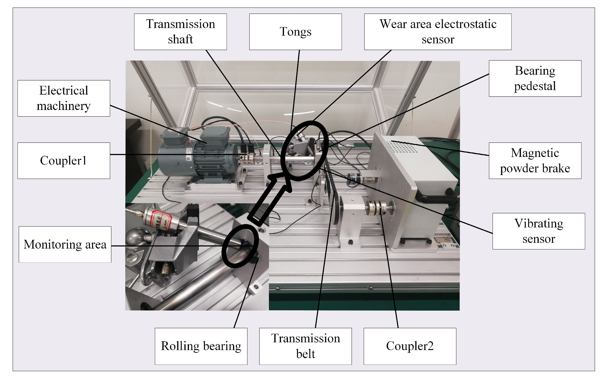
4.1. Experimental Setup

To further validate the effectiveness of the CcStOMP algorithm for real rolling bearing fault diagnosis, based on the principle of electrostatic monitoring, the rolling bearing electrostatic monitoring experimental platform shown in Figure 4 was built. The experimental platform is mainly composed of a motor, couplings, drive shafts, sensor fixtures, wear area electrostatic sensors, bearing housings, a magnetic particle brake, vibration sensors, a drive belt, and a motor controller. The motor and drive shaft are connected through the coupling 1 contact connection, motor rotation drives the rotary shaft rotation and is then installed in the bearing housing rotation, both of which share the same speed as the bearing inner ring rotation, the outer ring does not move, and the electrostatic sensors are fixed in the experimental platform near the wear monitoring region.
In order to further verify the effectiveness of the CcStOMP algorithm on the actual rolling bearing fault diagnosis, based on the principle of electrostatic monitoring, the rolling bearing electrostatic monitoring experimental platform shown in Figure 4 was built. The experimental platform is mainly composed of electrical machinery, a coupler, a transmission shaft, tongs, a wear area electrostatic sensor, a bearing pedestal, a magnetic particle brake, a vibration sensor, a transmission belt, a rolling bearing, and the monitoring area.
The main monitoring index of this experiment is the charge level of the friction vice, and the main structure of the adopted wear area electrostatic sensor is shown in Figure 5, which is mainly composed of the probe sensing surface, insulating layer, shielding layer, rear end cover, and signal output terminal. The experiment selected SKF-6204-2Z deep groove ball bearings as the research object, due to the rolling bearing on the preset outer ring failure and roller failure, and selected a gap width of 2.5 mm as the definition of a bearing failure. The rolling bearing parts used in the experiment are shown in Figure 6a,b, respectively.
The data acquisition steps in this experiment were as follows: the motor controller is assigned a preset speed, the motor drives the rolling bearings on the rotating shaft to rotate the wear and tear, and in the wear region produces a large number of charged particles. The anti-potential charge generated at the proximal end of the electrostatic sensor probe drives the same potential charge to the distal end of the probe surface, and the charge signal is converted into a voltage signal through the signal conditioning circuit. The electrostatic signal is amplified by a charge amplifier, converted into a digital signal through the data acquisition card, and transmitted to the data acquisition interface system. The electrostatic signal acquisition steps are shown in Figure 7.
The experimental parameters were set as follows: the bearing speed was 3800 r/min, the acquisition frequency was 12 KHz, the acquisition time was 1 s, and the outer ring fault frequency and roller fault frequency were calculated as 193.17 Hz and 126.03 Hz, respectively, according to the bearing fault theory. The rolling bearing electrostatic monitoring experimental platform constructed in Figure 4 was used to collect the faulty electrostatic signals of the bearing outer ring and the roller gravity. The main parameters of rolling bearings are shown in Table 1.
Figure 8a,b show the original electrostatic signal time-domain and frequency-domain plots of the experimental data for the outer ring of the bearing, and Figure 9a,b show the original electrostatic signal time-domain and frequency-domain plots of the experimental data for the bearing roller, respectively. f B P F O in the figure is the frequency of bearing outer ring failures for the bearing roller fault characteristic frequency. From Figure 8a and Figure 9a, it can be seen that the peak intensity of the outer ring fault amplitude is basically maintained within 10 mV, while the roller fault amplitude change is small, with the amplitude peak intensity maintained at 5 mV for both electrostatic fluctuations, indicating that the electrostatic induction is obvious. In Figure 8b, the outer ring fault frequency domain graph, there is a clear peak at frequency 191 Hz, but there are other obvious peaks near the frequency, thus causing interference to the fault characteristics. Its 2× frequency is not prominent enough and is subject to interference from the surrounding noise. In Figure 9b, the frequency domain graph of the roller fault, the fault frequency is 127 Hz, but the peak of the fault frequency is lower and it is not possible to quickly locate the frequency of its fault characteristics. There is also prominent noise interference around the fault frequency, which is not conducive to fault feature extraction. As a result, the electrostatic monitoring technology can effectively achieve feature extraction of rolling bearing faults, but it is easily disturbed by noise, so it is necessary to use a fault feature extraction method with excellent performance to complete the rolling bearing fault diagnosis task.
To verify that the CcStOMP algorithm has a better denoising effect in rolling bearing electrostatic monitoring signals, the experimental results are analysed in Section 4.2 and Section 4.3 with the bearing outer ring and roller faults as the representative. The same electrostatic signals were processed using the StOMP algorithm and the CcStOMP algorithm, and the time-domain map, sparse-domain map, and envelope spectra of reconstructed signals were obtained, so as to analyse the signal reconstruction and denoising capability.

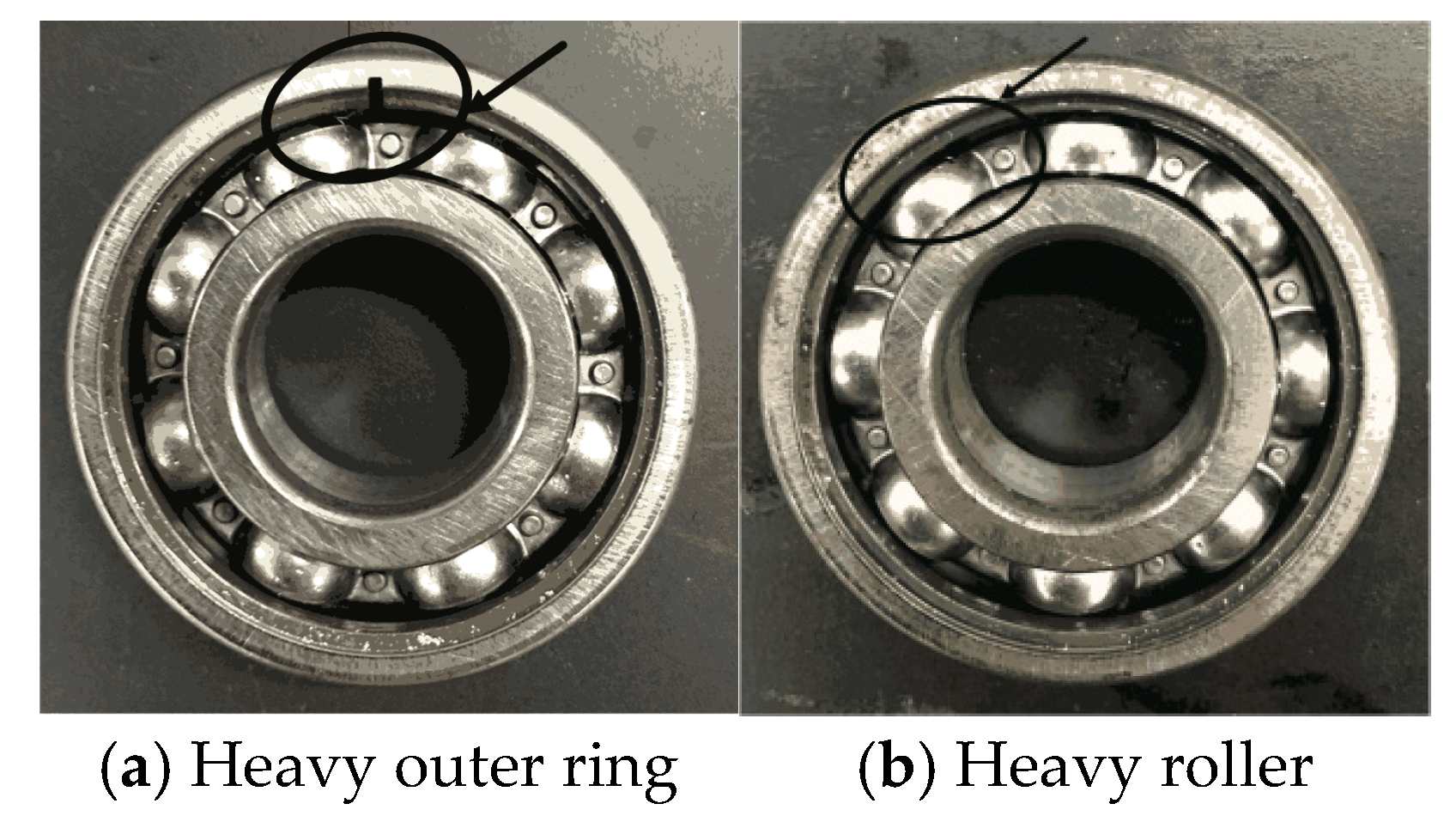
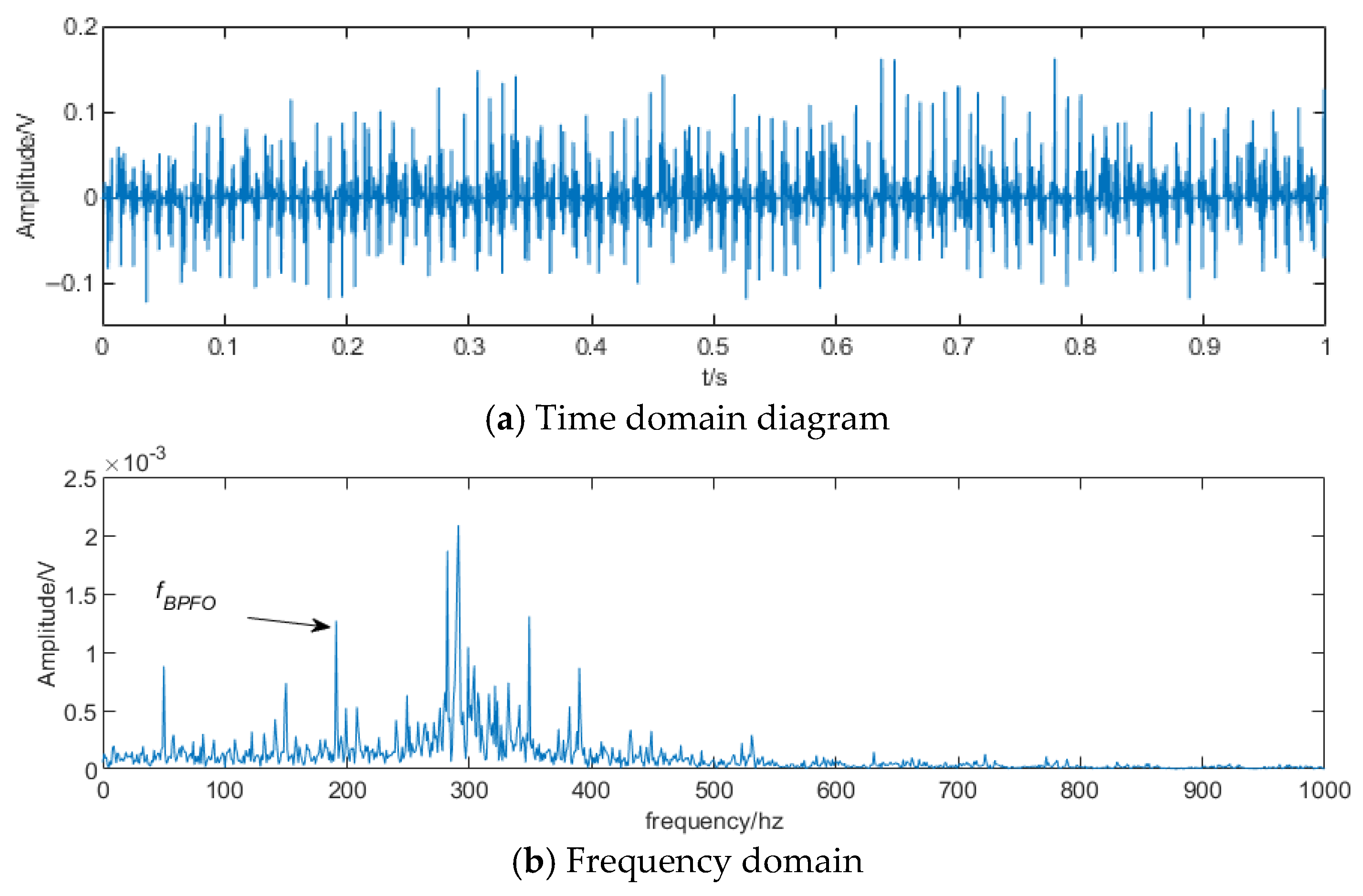
4.2. Analysis of Outer Race Fault Test Results

The time-domain diagrams, sparse-domain diagrams, and envelope spectra of the outer ring faults after StOMP processing are shown in Figure 10a–c, respectively, and the time-domain diagrams, sparse-domain diagrams, and envelope spectra of the outer ring faults after CcStOMP processing are shown in Figure 11a–c, respectively:
From the comparative analysis of Figure 10a and Figure 11a, it can be seen that the frequency of the fault characteristics of the CcStOMP algorithm is more prominent in the time-domain waveform plots of the signal reconstruction. Observing the distribution of sparse coefficients in Figure 10b and Figure 11b, the CcStOMP algorithm had a more superior sparse performance than the StOMP algorithm, while the distribution of matching atoms in the support set is more uniformly dense, and the weights1 are flatter. Comparing Figure 10c and Figure 11c, it can be seen that the StOMP algorithm can identify the fault eigenfrequency, but its fault characteristics are not prominent enough, it is easily affected by nearby noise, and it cannot identify multiple eigenfrequencies effectively; the CcStOMP algorithm can clearly identify the eigenfrequency of the outer ring fault of 2 Hz, and at the same time, it can clearly identify the eigenfrequency of the 2× frequency and the 3× frequency. The noise interference around the characteristic frequency is small, so the algorithm can quickly locate the fault characteristic frequency. The specific effects of two algorithms on bearing outer ring fault feature extraction is shown in Table 2.

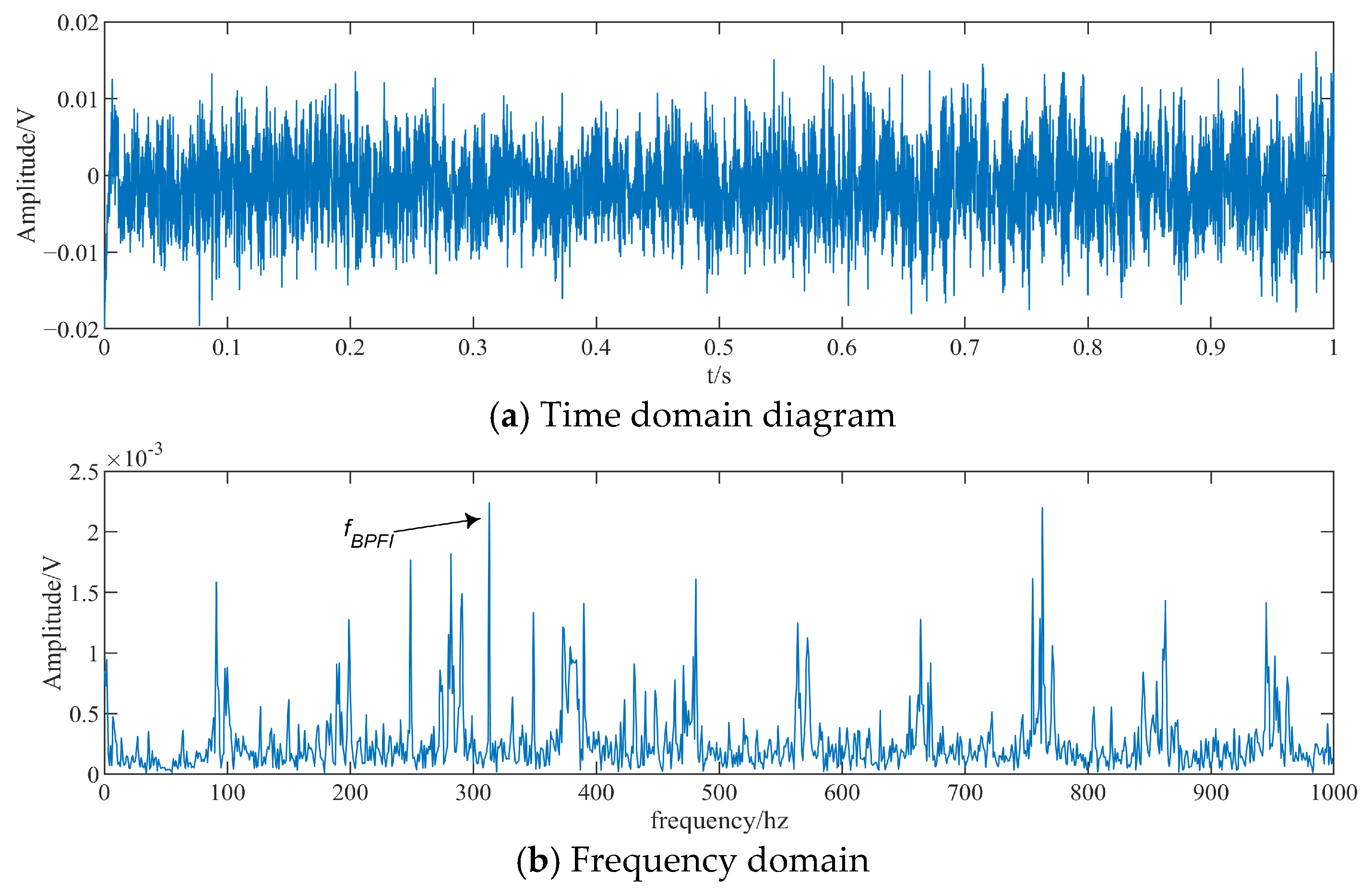
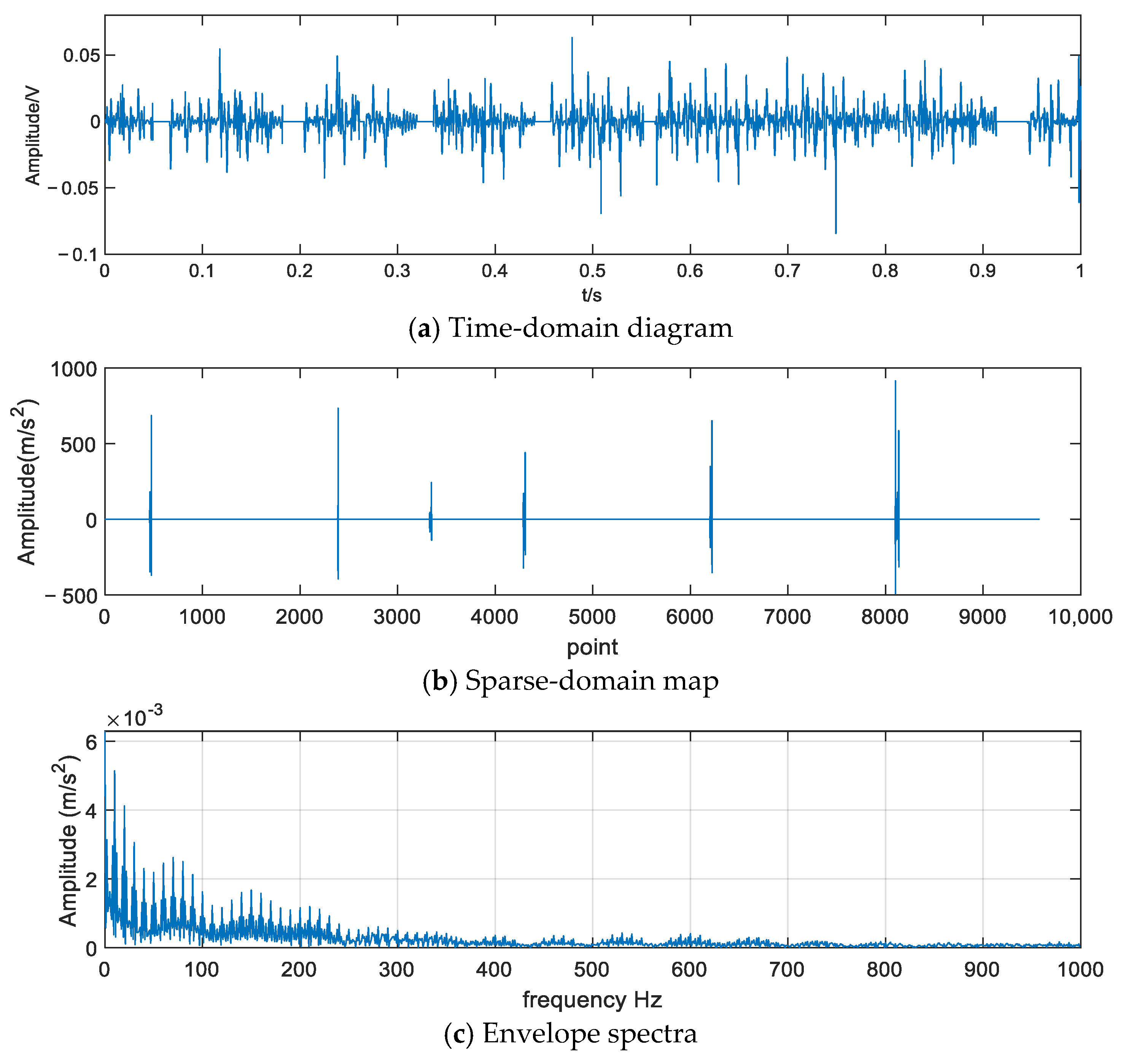
4.3. Analysis of Roller Failure Test Results

The time-domain map, sparse-domain map and envelope spectrum of roller faults after StOMP treatment are shown in Figure 12a–c, respectively, and the time-domain map, sparse-domain map and envelope spectrum of roller faults after CcStOMP treatment are shown in Figure 13a–c, respectively.
Observing Figure 12a and Figure 13a, the frequency of fault characteristics of the CcStOMP algorithm is more obvious when looking at the signal reconstruction time-domain waveform. Observing the distribution of sparse coefficients in Figure 12b and Figure 13b, the sparsity of the StOMP algorithm is poor, with fewer matching atoms in the support set and a scattered distribution; the sparsity of CcStOMP algorithm is good, with dense matching atoms in the support set, a uniform distribution, and smoother weights. Observing Figure 12c and Figure 13c, the CcStOMP algorithm is able to identify the characteristic frequency of roller faults more clearly, and at the same time, it can also clearly identify the 2× frequency of the characteristic frequency of faults without interference from the surrounding noise. The theoretical fault frequency of the roller fault can be seen, and the experimental data electrostatic signal fault characteristic frequency and the theoretical fault characteristic frequency indicate a weak error of 0.02%, so the identification of the error may have been a result of the actual rotation frequency and the theoretical frequency of rotation deviation, which led to the existence of the error, but as the error is relatively small, it can be ignored. The specific effects of the two algorithms on the bearing roller fault characteristic extraction are shown in Table 3.
Of the two types of sparse algorithms, the StOMP algorithm can identify fault feature frequency components, but compared with the CcStOMP algorithm, there is a significant lack of recognition accuracy, and it is easily affected by surrounding noise. This indicates that the CcStOMP algorithm has better performance for rolling bearing fault signal reconstruction and fault feature extraction.

5. Conclusions

Aiming at the problem that the fault features of rolling bearing fault electrostatic monitoring signals are not easily extracted and are easily affected by noise, in this study sparse representation theory was introduced into electrostatic signal processing, and the sparse representation method based on CcStOMP was adopted. This paper has analysed the shortcomings of the StOMP algorithm in sparse recovery accuracy and pointed out the pathological equation of weight determination as the main reason for the reduction of sparse recovery accuracy. CcStOMP adds a clustering contraction mechanism to the atom search process and filters the selected atoms twice, which makes the condition number of the support set more reasonable and improves the behaviour of the support set, thus improving the performance of sparse recovery. The comparative analysis of the experimental data shows that CcStOMP can effectively eliminate noise interference and retain effective electrostatic signals compared to StOMP, which verifies the effectiveness of CcStOMP algorithm for electrostatic signal fault feature extraction. In future research, we will study the selection of different models, different rotational speeds, and different failure degrees of rolling bearings for experiments so as to validate the effectiveness of CcStOMP and study the threshold selection and clustering contraction to update the atomic search strategy to further improve the accuracy of sparse recovery. Moreover, we will also further study the application of CcStOMP in other mechanical systems to expand its application areas.

Author Contributions

Conceptualization, R.L.; methodology, R.L. and H.Y.; validation, H.Y.; formal analysis, J.S.; data curation, H.Y. and L.Z.; writing-original draft preparation, R.L. and H.Y.; writing-review and editing, J.S.; visualization, L.Z.; supervision, R.L.; project administration, R.L.; funding acquisition, R.L. and J.S. All authors have read and agreed to the published version of the manuscript.

Funding

This study was approved for funding by the National Natural Science Foundation of China, project No. 51705221, U2233204, 52072176.

Data Availability Statement

The original contributions presented in this study are included in the article. Further inquiries can be directed to the corresponding author.

Acknowledgments

The authors sincerely thank the editors and reviewers for their comments and guidance.

Conflicts of Interest

The authors declare that they have no conflicts of interest/competing interests to declare that are relevant to the content of this article.

References

  1. He, L.F.; Zhu, W.; Zhang, G. Research and application of coupled two-dimensional asymmetric bistable stochastic resonance system. Chin. J. Phys. 2021, 73, 420–432. [Google Scholar] [CrossRef]
  2. Gbashi, S.M.; Olatunji, O.O.; Adedeji, P.A.; Madushele, N. From academic to industrial research: A comparative review of advances in rolling element bearings for wind turbine main shaft. Eng. Fail. Anal. 2024, 163, 108510. [Google Scholar] [CrossRef]
  3. Rejith, R.; Kesavan, D.; Chakravarthy, P.; Murty, S.N. Bearings for aerospace applications. Tribol. Int. 2023, 181, 108312. [Google Scholar] [CrossRef]
  4. de la Presilla, R.; Wandel, S.; Stammler, M.; Grebe, M.; Poll, G.; Glavatskih, S. Oscillating rolling element bearings: A review of tribotesting and analysis approaches. Tribol. Int. 2023, 188, 108805. [Google Scholar] [CrossRef]
  5. El Laithy, M.; Wang, L.; Harvey, T.J.; Vierneusel, B.; Correns, M.; Blass, T. Further understanding of rolling contact fatigue in rolling element bearings—A review. Tribol. Int. 2019, 140, 105849. [Google Scholar] [CrossRef]
  6. Wang, Z.; Shi, D.; Xu, Y.; Zhen, D.; Gu, F.; Ball, A.D. Early rolling bearing fault diagnosis in induction motors based on on-rotor sensing vibrations. Measurement 2023, 222, 113614. [Google Scholar] [CrossRef]
  7. Li, C.; Zhou, J.; Wu, X.; Liu, T. Phase-based video vibration measurement and fault feature extraction method for compound faults of rolling bearings. Adv. Eng. Inform. 2024, 62, 102897. [Google Scholar] [CrossRef]
  8. Ruochen, L.; Hongfu, Z. Mathematical model, simulation, and experimental calibration of electrostatic wear-Site sensor. IEEE Sens. J. 2017, 17, 2428–2438. [Google Scholar] [CrossRef]
  9. Tian, Z.; Lu, P.; Grundy, J.; Harvey, T.; Powrie, H.; Wood, R. Charge pattern detection through electrostatic array sensing. Sens. Actuators A Phys. 2024, 371, 115295. [Google Scholar] [CrossRef]
  10. Harvey, T.J.; Wood, R.J.K.; Powrie, H.E.G. Electrostatic wear monitoring of rolling element bearings. Wear 2007, 263, 1492–1501. [Google Scholar] [CrossRef]
  11. Harvey, T.J.; Wood, R.J.K.; Denuault, G.; Powrie, H.E.G. Investigation of electrostatic charging mechanisms in oil lubricated tribo-contacts. Tribol. Int. 2002, 35, 605–614. [Google Scholar] [CrossRef]
  12. Harvey, T.J.; Morris, S.; Wang, L.; Wood, R.J.K.; Powrie, H.E.G. Real-time monitoring of wear debris using electrostatic sensing techniques. Proc. Inst. Mech. Eng. Part J. J. Eng. Tribol. 2007, 221, 27–40. [Google Scholar] [CrossRef]
  13. Zhang, Y.; Wang, A.; Zuo, H. Roller Bearing Performance Degradation Assessment Based on Fusion of Multiple Features of Electrostatic Sensors. Sensors 2019, 19, 824. [Google Scholar] [CrossRef] [PubMed]
  14. Bai, R.; Li, J.; Liu, J.; Shi, Y.; He, S.; Wei, W. Day-ahead photovoltaic power generation forecasting with the HWGC-WPD-LSTM hybrid model assisted by wavelet packet decomposition and improved similar day method. Eng. Sci. Technol. Int. J. 2025, 61, 101889. [Google Scholar] [CrossRef]
  15. Chen, C.; Luo, Y.; Liu, J.; Yi, Y.; Zeng, W.; Wang, S.; Yao, G. Joint sound denoising with EEMD and improved wavelet threshold for real-time drilling lithology identification. Measurement 2024, 238, 115363. [Google Scholar] [CrossRef]
  16. Salunkhe, V.G.; Desavale, R.G.; Khot, S.M.; Yelve, N.P. A Novel Incipient Fault Detection Technique for Roller Bearing Using Deep Independent Component Analysis and Variational Modal Decomposition. J. Tribol. 2023, 145, 7. [Google Scholar] [CrossRef]
  17. Salunkhe, V.G.; Khot, S.M.; Jadhav, P.S.; Yelve, N.P.; Kumbhar, M.B. Experimental Investigation Using Robust Deep VMD-ICA and 1D-CNN for Condition Monitoring of Roller Element Bearing. J. Comput. Inf. Sci. Eng. 2024, 24, 12. [Google Scholar] [CrossRef]
  18. Song, L.; Yan, R. Bearing fault diagnosis based on Cluster-contraction Stage-wise Orthogonal-Matching-Pursuit. Measurement 2019, 140, 240–253. [Google Scholar] [CrossRef]
  19. Zheng, S.; Liu, T.; Liu, C. Composite fault diagnosis method of rolling bearings based on sparse representation of cascaded over-complete dictionary. Vib. Shock. 2021, 40, 174–179. [Google Scholar]
  20. Sun, R.; Yang, Z.; Chen, X.; Tian, S.; Xie, Y. Gear fault diagnosis based on the structured sparsity time-frequency analysis. Mech. Syst. Signal Process. 2018, 102, 346–363. [Google Scholar] [CrossRef]
  21. Deng, F.; Qiang, Y.; Yang, S.; Hao, R.; Liu, Y. Sparse representation of parametric dictionary based on fault impact matching for wheelset bearing fault diagnosis. ISA Trans. 2021, 110, 368–378. [Google Scholar] [CrossRef]
  22. He, G.; Ding, K.; Lin, H. Fault feature extraction of rolling element bearings using sparse representation. J. Sound Vib. 2016, 366, 514–527. [Google Scholar] [CrossRef]
  23. Wang, L.; Cai, G.; You, W. Transients Extraction Based on Averaged Random Orthogonal Matching Pursuit Algorithm for Machinery Fault Diagnosis. IEEE Trans. Instrum. Meas. 2017, 66, 3237–3248. [Google Scholar] [CrossRef]
  24. Donoho, D.L.; Tsaig, Y.; Drori, I.; Starck, J.L. Sparse Solution of Underdetermined Systems of Linear Equations by Stagewise Orthogonal Matching Pursuit. IEEE Trans. Inf. Theory 2012, 58, 1094–1121. [Google Scholar] [CrossRef]
  25. Chen, X.; Du, Z.; Li, J.; Li, X.; Zhang, H. Compressed sensing based on dictionary learning for extracting impulse components. Signal Process. 2014, 96, 94–109. [Google Scholar] [CrossRef]
Figure 1. Principle of Electrostatic Monitoring.
Lubricants 13 00178 g001
Figure 2. Solving process of StOMP algorithm.
Lubricants 13 00178 g002
Figure 3. Schematic diagram of clustering contraction mechanism.
Lubricants 13 00178 g003
Figure 4. Experimental platform for electrostatic monitoring of rolling bearings.
Lubricants 13 00178 g004
Figure 5. Electrostatic sensor.
Lubricants 13 00178 g005
Figure 6. Experimental parts of rolling bearing.
Lubricants 13 00178 g006
Figure 7. Experimental data collection procedure for rolling bearings.
Lubricants 13 00178 g007
Figure 8. Outer ring fault experiment original electrostatic signal.
Lubricants 13 00178 g008
Figure 9. Roller failure experiment original electrostatic signal.
Lubricants 13 00178 g009
Figure 10. Reconstruction results of StOMP algorithm for outer ring fault.
Lubricants 13 00178 g010
Figure 11. Reconstruction results of CcStOMP algorithm for outer ring fault.
Lubricants 13 00178 g011
Figure 12. Reconstruction results of StOMP algorithm for roller fault.
Lubricants 13 00178 g012
Figure 13. Reconstruction results of CcStOMP algorithm for roller fault.
Lubricants 13 00178 g013
Table 1. Main parameters of experimental rolling bearings.
TypeParameterTypeParameter
Bearing designationSKF-6204-2ZPitch diameter/mm33.5
Roller diameter/mm7.94Number of rollers/n8
Contact angle/°0Defect width/mm2.5
Table 2. Comparison of the effect of fault feature extraction in the outer ring.
TypeFault Character Frequency/HzFault Characteristics Are Disturbed by NoiseTwice the Fault Characteristic Frequency/Hz
Theoretical fault193.17/386.34
StOMP191.07severeDisturbed by noise, unrecognizable
CcStOMP191.75clear384.54
Table 3. Comparison of roller fault feature extraction effect.
TypeFault Character Frequency/HzFault Characteristics Are Disturbed by NoiseTwice the Fault Characteristic Frequency/Hz
Theoretical fault126.03/252.06
StOMP126severeDisturbed by noise, unrecognizable
CcStOMP126clear252
Disclaimer/Publisher’s Note: The statements, opinions and data contained in all publications are solely those of the individual author(s) and contributor(s) and not of MDPI and/or the editor(s). MDPI and/or the editor(s) disclaim responsibility for any injury to people or property resulting from any ideas, methods, instructions or products referred to in the content.

