Article

Experimental Study on Thermal Elastohydrodynamic Lubrication Performance Calculation and Take-Off Speed of Thrust Bearing of Canned Motor Pump

1
Zhengzhou Research Institute of Mechanical Engineering (ZRIME) Gearing Technology Co., Ltd., Zhengzhou 450001, China
2
School of Mechanical and Precision Instrument Engineering, Xi’an University of Technology, Xi’an 710048, China
3
School of Mechanical Engineering, Xi’an Jiaotong University, Xi’an 710049, China
4
Department of Mechanical Engineering, Xi’an Jiaotong University City College, Xi’an 710018, China
5
Engineering Research Center of Robot and Intelligent Manufacturing, Universities of Shaanxi Province, Xi’an 710018, China
*
Author to whom correspondence should be addressed.
Lubricants 2025, 13(4), 191; https://doi.org/10.3390/lubricants13040191
Submission received: 24 December 2024 / Revised: 18 February 2025 / Accepted: 23 February 2025 / Published: 21 April 2025

Abstract

:
In this paper, the calculation model and method of the lubrication performance of the thrust bearing, which considers the thermal bomb deformation, are constructed based on the working characteristics of the main pump thrust of the nuclear power plant. The key design parameters of the tile package Angle θ are analyzed by taking the design parameters of the thrust-bearing tile as the variable. The circumferential fulcrum coefficient of tile, the influence of tile thickness B, and tile elastic modulus E on the lubrication performance of thrust bearing are analyzed to obtain improved design parameters. The lubrication performance of the thrust bearing includes the minimum oil film thickness hmin, the maximum temperature of oil film Tmax, total flow Qx, total power consumption W, maximum thermal deformation of axial bush δTmax, and the maximum elastic deformation of the axial bush δFmax. The scale test of the designed thrust bearing is carried out. The take-off speed of the bearing is tested and compared with the results of the theoretical analysis. The study results show that the influence is becoming more obvious from θo to hmin. Moreover, the impact becomes more obvious from Tmax to Qx, B to hmin, and Qx to δTmax and δFmax. Lastly, the impact is also obvious from E to Qx and δFmax.

1. Introduction

The nuclear main pump is used to drive the coolant to circulate in the system in the primary circuit of the nuclear island. The nuclear main pump is used in nuclear power plants and submarines [1,2]. In nuclear power plants, the main pump is located in the heart of the nuclear island. Each steam generator has a main pump used to convert the hot water pump in the evaporator into heat energy. The water circulation in nuclear power operations must be controlled [3,4]. The nuclear main pump shaft system is generally a vertical shaft system. The shaft system is mainly subjected to an axial load. The axial load is generated by the impeller’s dead weight and hydraulic action [5]. The lubrication performance of the thrust bearing of the nuclear main pump directly affects the thickness of the oil film between the pad, the thrust disc, and the bearing capacity of the pad. The relevant design, simulation, and experimental research on the thrust bearing of the nuclear main pump must be carried out to avoid bearing failure caused by poor lubrication performance.
Zhang et al. provided a calculation method for bearing dynamic characteristics, considering the inertia of the bearing bush for the radial bearing of the nuclear main pump. The author calculated the dynamic characteristic coefficient of the pump under different journal whirl frequencies and analyzed the bearing stability [6]. Jia et al. established a performance calculation model of the main pump guide bearing considering thermoelastic deformation for the third-generation nuclear power AP1000 main pump. The author also calculated and analyzed the influence of design parameters on performance [7]. Liu et al. investigated the main pump bearing. The shortcomings of the original bearing structure design were pointed out by aiming at the wear phenomenon of the main thrust pad during the heavy-duty idle shutdown [8]. Liu et al. provided the method of considering the failure mode correlation, calculated the reliability of the thrust-bearing positioning mechanism system, and conducted the reliability analysis of the failure mode correlation of the thrust-bearing positioning mechanism of the nuclear main pump [9]. Wang et al. analyzed the process method of positioning the bidirectional thrust-bearing center of the nuclear main pump motor. The author successfully developed a process technology for positioning the bidirectional thrust-bearing center [10]. Lei et al. established the quantitative relationship between the machining process, load, and the material processing load of the nuclear main pump bearing parts and the surface interface integrity. The author proposed the machining method of the parts geometry, material, and structure of the thrust bearing with the surface interface integrity as the performance control quantity [11]. Tang et al. designed an improved thrust pad to solve the problem of the upper thrust pad’s high temperature by optimizing the thrust pad’s geometric parameters [12]. Xu selected three typical idling conditions of the main pump. The author used the basic principles of fluid mechanics and tribology to calculate the minimum oil film thickness change of the main thrust bearing in each working condition. Moreover, the author compared and analyzed the increase in bearing temperature to evaluate the friction state of the bearing in each period [13]. Wang explored the friction and wear, and mechanical properties of the friction pair material of the main pump bearing. The investigated friction pair has a low friction coefficient and specific wear rate and can withstand high temperatures and high-dose irradiation [14]. Li et al. designed and built a test system for scaled-down tilting pad thrust bearings, and the feasibility of the scaled-down scheme was verified [15]. Kumar et al. focus on evaluating the performance of a Rayleigh step bearing under thermo-mixed-EHL condition, combining the effect of deterministic and stochastic surface roughness [16]. Cao et al. aim to reveal the transient thermo-elasto-hydrodynamic lubrication mechanism of a bidirectional thrust bearing in a pumped-storage unit, and to propose the transient simulation method of two-way fluid–solid–thermal interaction of the thrust bearing [17]. Ma et al. calculated the support stiffness, overturning stiffness, and flow rate for both thrust and journal bearings. Additionally, a numerical analysis is conducted to examine the influence of the oil film thickness, inlet pressure, and restrictor size on the operational characteristics of the bearings, revealing the interplay between an eccentric load and journal bearing speed [18]. Yavelov conducted a study of the performance of a thrust sliding bearing in startup and rundown regimes—the bench was adapted for testing both when the bearing is lubricated with oil and when lubricated with water [19].
At present, there are few comparative studies on the thermal elastohydrodynamic lubrication performance of large thrust bearings considering various design and operating parameters. In this paper, the key design parameters of the pad are studied based on the lubrication performance of the tilting pad thrust bearing of the nuclear main pump. Lastly, the related calculation and analysis are carried out. The innovation of this paper is that, from the perspective of the thermoelastic deformation of large tilting pad thrust bearings, the lubrication performance of bearings is systematically studied. Another innovation of this paper is that the test method of the thrust-bearing take-off speed is given.

2. Structure of Thrust Bearing of the Canned Motor Pump and Design Parameters of Pad

2.1. Structure of Thrust Bearing of Canned Motor Pump

In this paper, the thrust bearing of the second-generation nuclear main pump is taken as the research object. The second-generation pump shaft system is a vertical shaft system, with the structure shown in Figure 1. The nuclear main pump shaft system comprises three radial bearings, a single bidirectional thrust bearing, an impeller, and a flywheel assembly. The thrust bearing bears the main load when the shaft system operates.
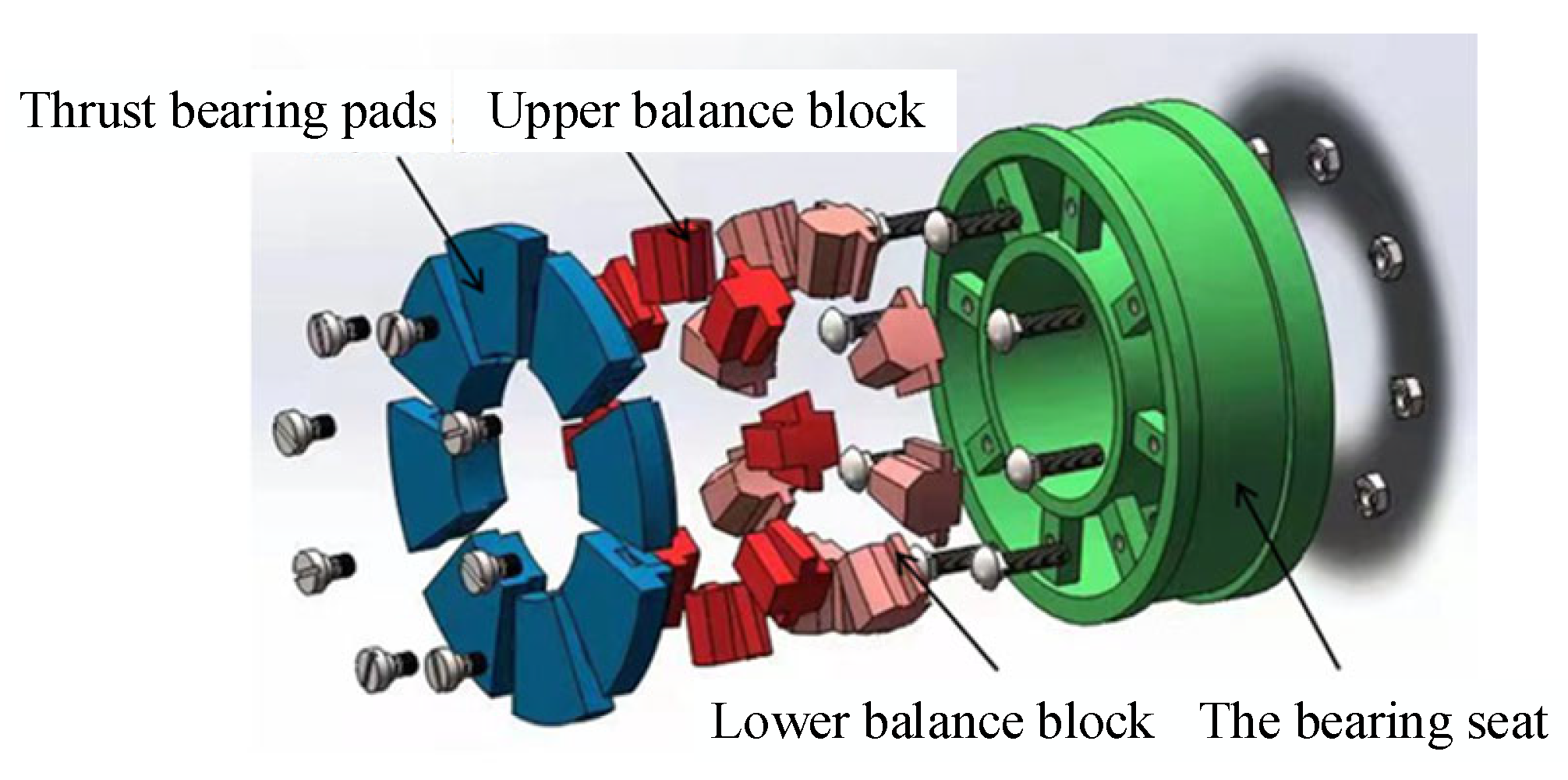
In this paper, the analysis is mainly aimed at the resultant force of the downward force and gravity of the impeller in Figure 1, when the axial force is vertical downward. At this time, the lower pad of the thrust bearing is stressed, and the explosion diagram of the lower pad structure of the thrust bearing is shown in Figure 2. The thrust-bearing structure is a balance pad supporting the thrust bearing, mainly composed of a thrust-bearing bush, upper balance pad, lower balance pad, and bearing seat. The advantage of using the balance pad is that the lever principle plays a certain load-sharing effect when the shaft diameter is tilted, or the installation height of the bearing tile is uneven. Moreover, the force of each tile is continuously and automatically adjusted to make the load of each tile uniform.

2.2. Main Design Parameters of Thrust-Bearing Pad of Canned Motor Pump

As a key part of the shaft system of the nuclear main pump, the thrust bearing must bear a relatively large axial load. The maximum axial load can reach 1000 kN. The maximum working speed of the main pump is 1800 r/min, and the rated working speed is 1500 r/min. This paper selects a set of working condition parameters of the thrust bearing of the nuclear main pump based on the actual use background, as shown in Table 1. These parameters are also the basis for the calculation input of this paper.
The main design parameters of the thrust-bearing fan-shaped tile include the inner diameter of the tile, the outer diameter of the tile, the wrap angle of the tile θo, the fulcrum coefficient of the tile, and the thickness of the tile and the elastic modulus of the tile. The general values are shown in Table 2.

3. Calculation Method of Thermal Elastohydrodynamic Lubrication Performance of Thrust Bearing

The Reynolds equation is a specialized form of the Navier–Stokes equations, utilized to describe the flow of fluid within a lubrication film. To simplify the Reynolds equation, it is customary to introduce certain assumptions and conditions that are deemed reasonable in practical engineering applications. The following are the simplification conditions for the Reynolds equation: The lubricant is a Newtonian fluid, meaning the shear stress of the fluid is linearly related to the shear rate. This foundational assumption for simplifying the equation is applicable to most mineral oils; the viscosity remains constant across the thickness of the lubrication film; there are no eddies or turbulence within the oil film; the influence of inertial forces, including the force due to fluid acceleration and the centrifugal force from the curvature of the oil film, is negligible compared to viscous forces; the effect of body forces (such as gravity or magnetic forces) is ignored; there is no slip at the interface, meaning the velocity of the fluid adjacent to the surface is equal to the surface velocity; the pressure gradient across the thickness of the lubrication film can be neglected; the fluid is assumed to be incompressible, implying that the density of the fluid remains constant throughout the flow process; the upper and lower surfaces of the lubrication film are considered rigid, with only the inclined surface in motion. These simplification conditions render the Reynolds equation more concise in form, facilitating its solution and application.
The basic equations describing the thermal elastohydrodynamic lubrication model of thrust bearing include the Reynolds equation, oil film thickness equation, lubricant viscosity–temperature equation, and energy equation. The following two-dimensional Reynolds equation is obtained by neglecting the compressibility of the liquid and the inertia force of the fluid and by not considering the deformation of the thrust plate [20]:
For the thrust bearing under investigation in this study, the critical Reynolds number Re0, which signifies the transition from laminar to turbulent flow conditions, has been the subject of extensive experimental and theoretical analysis. The consensus from the majority of these studies indicates that the bearing fully enters the turbulent lubrication regime when the Reynolds number Re reaches a range of 1000~1500. In the computational analysis presented in this paper, the critical Reynolds number adopted is Re0 = 1500.
r r h 3 12 μ p r + 1 r θ h 3 12 μ p θ = ω r 2 h θ .
The pressure boundary conditions are p θ | Γ 1 = 0 and p | Γ 1 = 0 , where Γ1 is the boundary of the oil film rupture, and Γ is the boundary around the oil film.
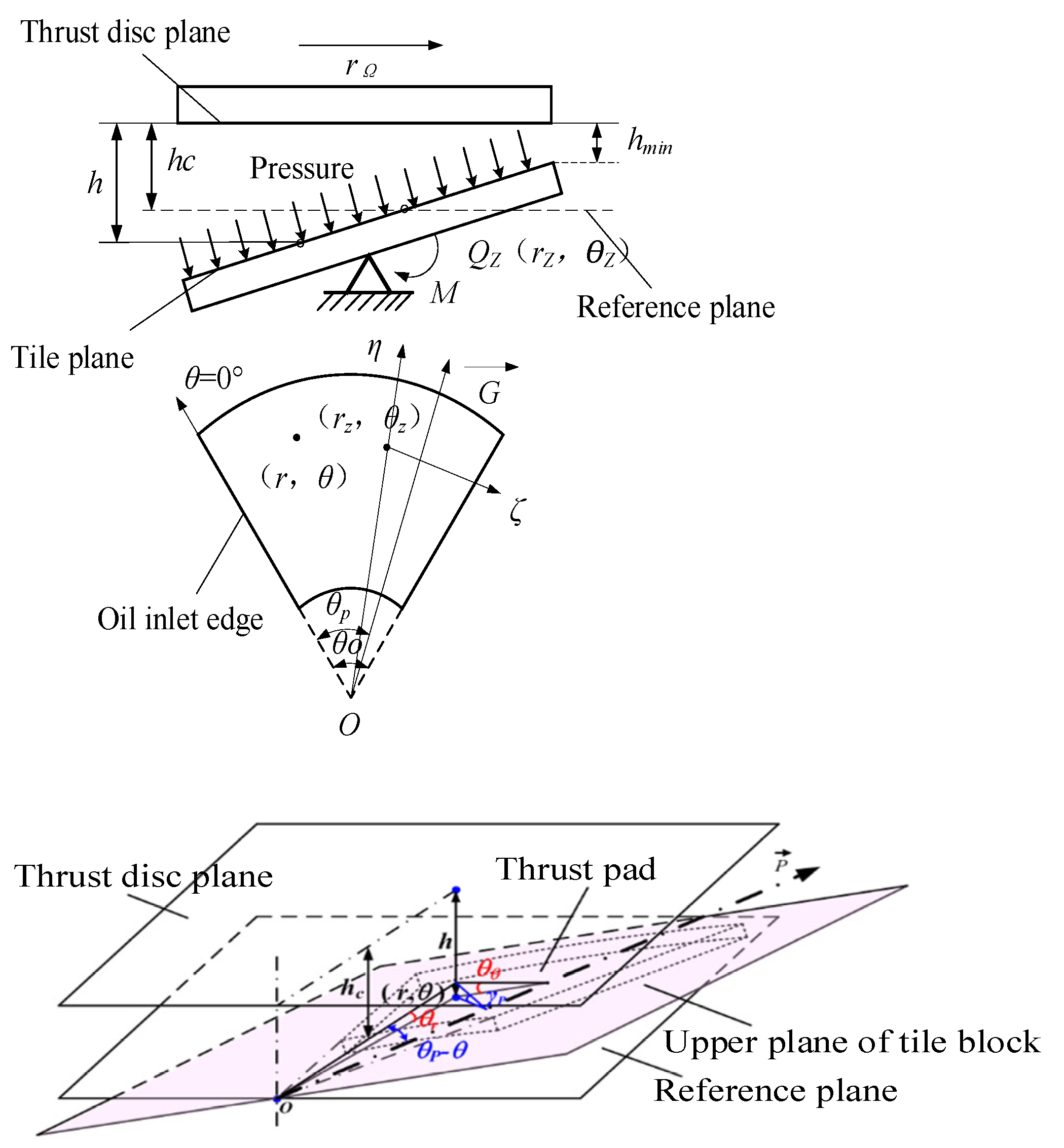
A reference plane parallel to the thrust plate plane is taken two planes away from the hc, as shown in Figure 3. The intersection of the tile plane and the reference plane after the tile swing is p , where p line through the tile fulcrum position. Parameter γp is the angle between the tile plane and the reference plane after the swing, i.e., the rotation angle of the bearing around the p line. The oil film thickness is as follows [20]:
h = h c + r sin θ p θ sin γ p h c + γ p r sin θ p θ .
Since γp is very small, sin γ p γ p , where θp is the angle of p , the angle between the oil inlet edge and p . The tile swing around the fulcrum forms parameters γp and θp. It is assumed that the swing angle is formed by the swing of the tile around the radius line (the line connecting the fulcrum with the bearing center) and the circumferential line where the fulcrum is located in the circumferential swing angle θθ and the radial swing angle θr, respectively. According to the geometric relationship [20],
sin θ p θ sin γ p = sin θ r sin θ p θ sin γ p / tan θ p θ = sin θ θ .
Assuming that the minimum oil film thickness is located at (rm, θm), the minimum oil film thickness hm obtained from the above equation is
h m = h c + γ p r m sin θ p θ m .
Equation (2) can be solved based on Equation (4). The expression of oil film thickness with respect to the minimum oil film thickness can be obtained as follows:
h = h m + γ p r sin θ p θ r m sin θ p θ m .
The deformation of the thrust tile includes the elastic deformation caused by the pressure of the oil film and the thermal deformation caused by the uneven distribution of the bearing temperature. The mechanical elastic deformation belongs to the same order of magnitude as the thermal deformation. In this paper, tile deformation is equivalent to the one-dimensional beam deformation. The membrane thickness equation of the deformation is shown in Equation (6) [20]:
h = h m + γ p r sin θ p θ r m sin θ p θ m + δ F + δ T ,
where δF is the elastic deformation, and δT is the thermal deformation.
Assuming that the winding curve of equal thickness tile is quadratic, the elastic deformation expression is shown in Equation (7):
δ F = δ F ( r , θ ) = 0.224 F wi x 2 E H w 3 ,
where Fwi is a single-watt load, E is the elastic modulus, Hw is the tile thickness, and x is the distance from any point to the fulcrum on the tile.
x = r 2 + r z 2 2 r r z cos θ θ z .
The radial expansion deformation caused by the temperature increase is neglected. Hence, the thermal deformation due to the temperature difference between the tile surface and the back tile is calculated. The thermal deformation of the distance from the fulcrum x is [21]
δ T = δ T ( r , θ ) = α p Δ T x 2 2 H w ,
where αp is the thermal expansion coefficient of the tile pad, and ΔT is the temperature difference between the tile surface and the tile back.
The approximate calculation formula of the temperature difference ΔT for the point support bearing is [22]
Δ T = ( 0.6 0.9 ) μ 0.1 0.14 p m 0.45 0.48 V m 0.56 0.60 ,
where μ is the dynamic viscosity of the water under ambient temperature (oil tank temperature); pm is the average specific pressure; and Vm is the average line velocity. The thermoelastic deformation of the tile is the sum of elastic deformation and thermal deformation. The thermoelastic deformation is shown in Equation (11):
δ = δ F + δ T = 0.224 F wi x 2 E H w 3 + α p Δ T x 2 2 H w .
Let δ = h min δ ¯ , x = B x ¯ , and Δ T = T 0 Δ T ¯ . Then, the dimensionless thermal elastic deformation can be expressed as Equation (12):
δ ¯ = a 1 + a 2 Δ T ¯ x ¯ 2 ,
where a 1 = 0.224 F wi B 2 h min E H w 3 and a 2 = α p T 0 B 2 2 h min H w .
x ¯ = r ¯ 2 + r ¯ z 2 2 r ¯ r ¯ z cos θ θ z
ρ C p ω r h 2 h 3 12 μ 1 r p θ 1 r t θ h 3 12 μ p r t r = μ ω 2 r 2 h + h 3 12 μ p r 2 + 1 r p r 2 ,
where Γ is the tile surface boundary, the boundary condition is t r = 0 , r = R 1 , t = tin , and θ = 0 .
When the pressure of the mineral oil exceeds 20 MPa, the viscosity starts to change significantly with the pressure. However, the pressure is lower than this value in the general thrust bearing with low secondary contact. Generally, only the viscosity–temperature relationship is considered in the numerical calculation. The dynamic viscosity and temperature of the oil meet the following formula:
μ = A e B / ( t + C ) ,
where A, B, and C are constants, which should be fitted according to the physical property parameters. The bearing capacity of a single thrust pad can be obtained by integrating the oil film pressure [20]:
W i = 0 θ 0 R 1 R 2 p r d r d θ = μ 0 ω B 4 h m 2 0 1 R ¯ 1 R ¯ 2 p ¯ r ¯ d r ¯ d θ = μ 0 ω B 4 h m 2 W ¯ i ,
where W i ¯ is the bearing capacity of the dimensionless single-block thrust tile. The frictional moment Mi of a single thrust pad tile is
M i = 0 θ 0 R 1 R 2 μ r ω h + h 2 r p θ r 2 d r d θ = μ 0 ω B 4 h m 0 1 R ¯ 1 R ¯ 2 r ¯ h ¯ + h ¯ 2 r ¯ p ¯ θ r ¯ 2 d r ¯ d θ = μ 0 ω B 4 h m M ¯ i ,
where M i ¯ is the friction moment of a dimensionless single tile. The single-watt pad power consumption Pi is
P i = M i ω
The flow rate Qin of the oil inlet side of a single thrust-bearing pad is [20]
Q in = R 1 R 2 q d r = R 1 R 2 ω r h 2 h 3 12 μ p r θ θ = 0 d r = h m ω B 2 R ¯ 1 R ¯ 2 r ¯ h ¯ 2 h ¯ 3 12 r ¯ p ¯ θ θ = 0 d r ¯ = h m ω B 2 Q ¯ in
where Q ¯ in is the infinite flow rate of a single tile into the oil side. The oil displacement Q ¯ out of the oil outlet side of the single thrust-bearing pad is
Q out = R 1 R 2 q d r = R 1 R 2 ω r h 2 h 3 12 μ p r θ θ = θ 0 d r = h m ω B 2 R ¯ 1 R ¯ 2 r ¯ h ¯ 2 h ¯ 3 12 r ¯ r ¯ p ¯ θ θ = θ 0 d r ¯ = h m ω B 2 Q ¯ o   ,
where Q ¯ out is the oil discharge of a single tile. The discharge flow Qnx of the inner edge side of the single tile is
Q nx = 0 θ 0 h 3 r 12 μ p r r = R 1 d θ = h m ω B 2 θ 0 12 0 θ 0 h ¯ 3 r ¯ p ¯ r ¯ R = R 1 ¯ d θ = h m ω B 2 θ 0 12 Q ¯ nx ,
where Q ¯ nx is the dimensionless single tile inner edge side discharge. The leakage flow Qwx of the outer edge of the thrust-bearing single bearing is
Q wx = 0 θ 0 h 3 r 12 μ p r r = R 2 d θ = h m ω B 2 θ 0 12 0 θ 0 h ¯ 3 r ¯ p ¯ r ¯   r ¯ = R 2 ¯ d θ = h m ω B 2 θ 0 12 Q ¯ wx ,
where Q ¯ wx is the lateral discharge of the outer edge of a single tile. The total discharge Qx of the thrust bearing is
Q x = Q nx + Q wx ,
The discharge ratio is Q x / ( Q x + Q out ) . The discharge of the thrust-bearing pad is shown in Figure 4.
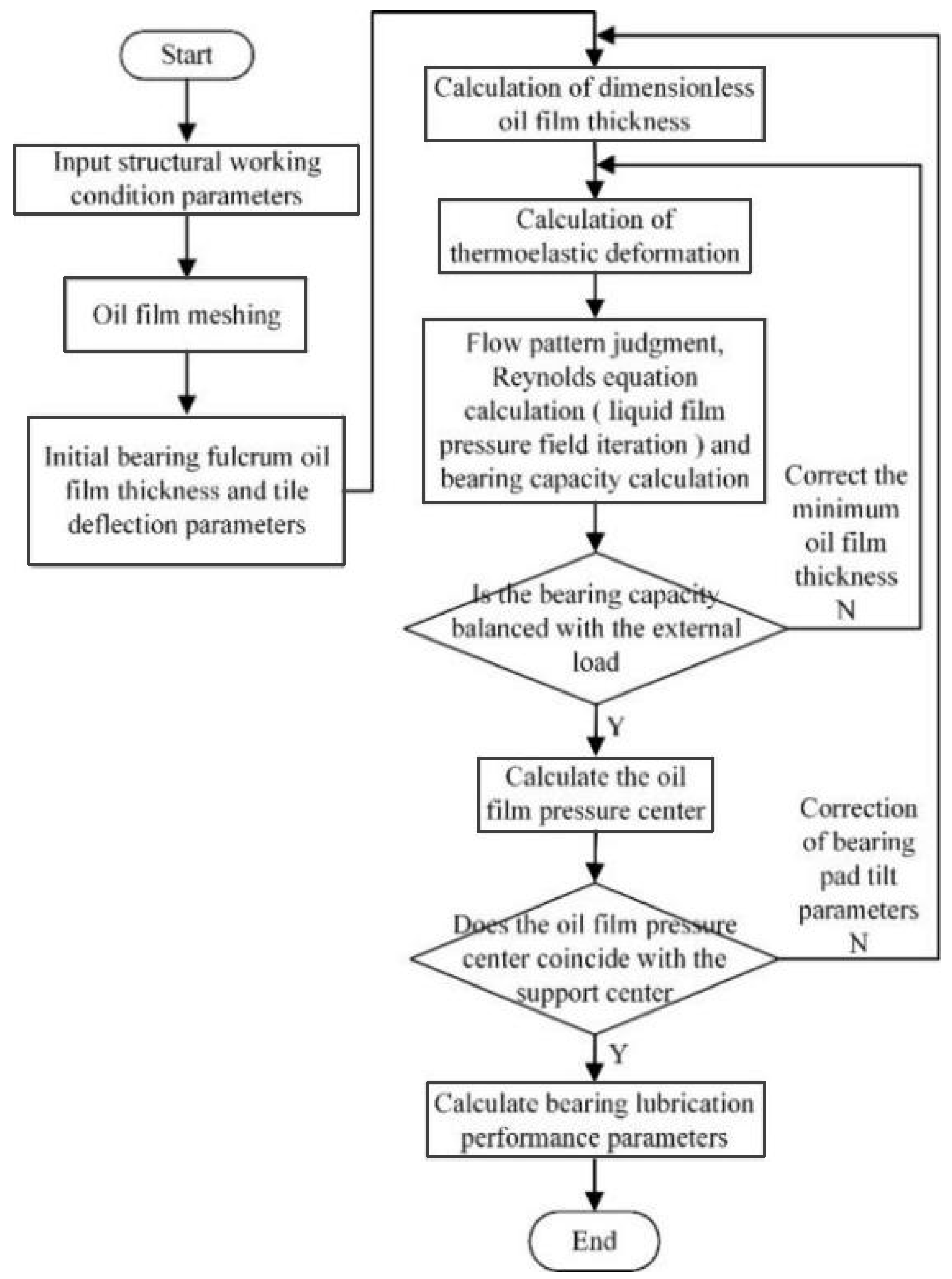
The thermal elastic flow lubrication model’s calculation process is a multiple iteration process of the basic equation and tile balance. The designed calculation schemes differ due to various requirements, mainly in the different equations and the number of iteration layers. In this paper, the calculation process of hot elastic flow lubrication performance of the thrust bearing is shown in Figure 5. The process in the figure includes three layers of iterations: liquid film pressure field iteration, bearing bush bearing capacity iteration, and tile balance position iteration.

4. The Influence of Design Parameters of Thrust-Bearing Pad on Lubrication Performance of Canned Motor Pump

This paper adopts the upper section’s relevant bearing working conditions and structural parameters. Furthermore, the thermal elastohydrodynamic lubrication characteristics analysis model and calculation method of thrust bearing are adopted. The influence of design parameters on the bearing lubrication performance is explored for the key design parameters of the bearing pad, such as the pad wrap angle, pad circumferential fulcrum coefficient, pad thickness, and pad elastic modulus. The bearing’s basic working condition parameters and dimensions are shown in Table 1 and Table 2. The calculated bearing lubrication performance parameters include the minimum oil film thickness hmin, the maximum temperature of oil film Tmax, and the total flow Qx. The total power consumption is W, the maximum thermal deformation of the axial bush is δTmax, and the maximum elastic deformation of the axial bush is δFmax.

4.1. Effect of Tile Wrap Angle on Lubrication Performance

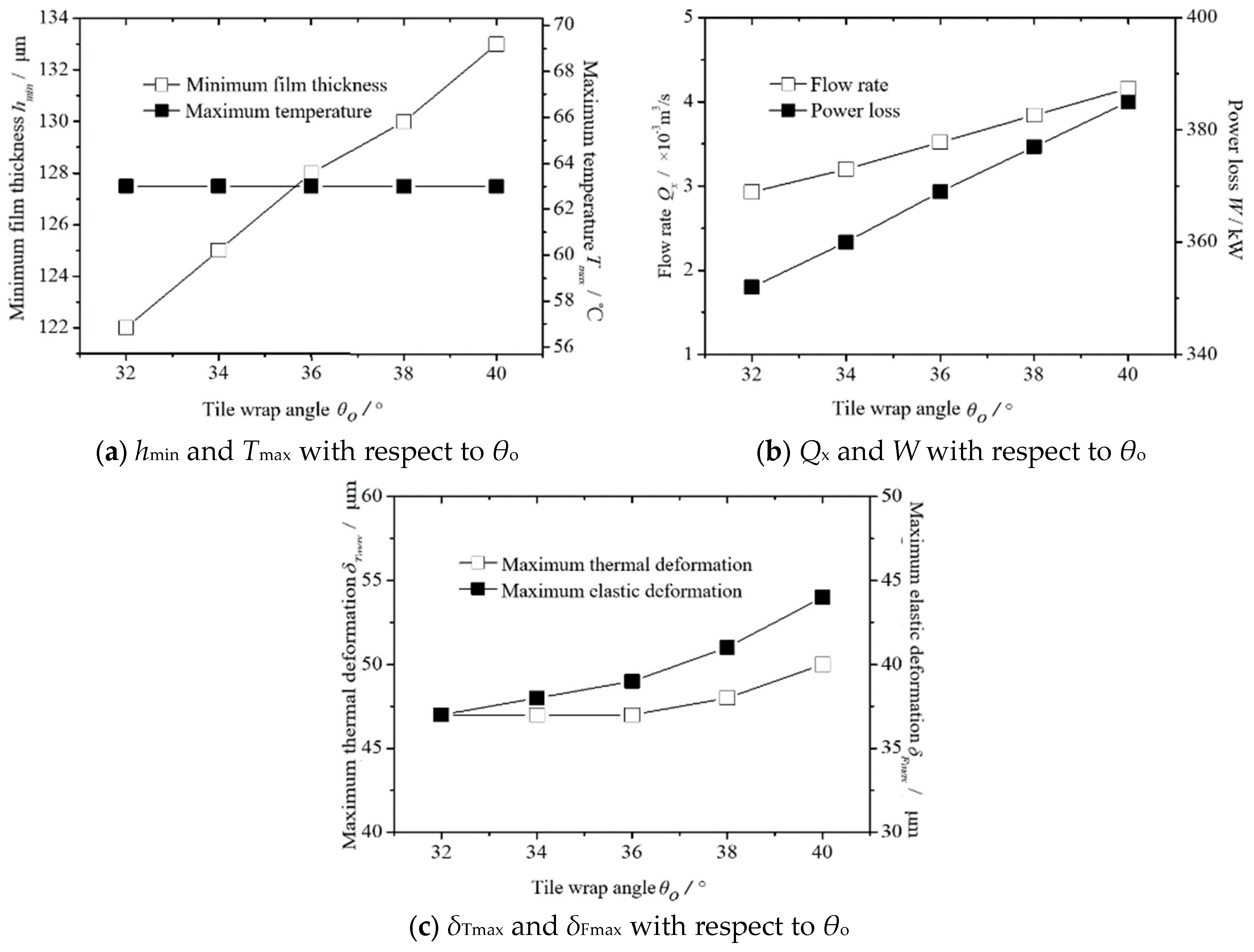
The thermo-elastic lubrication performance of the thrust bearing is calculated when the pad wrap angle θo is 32–40°. The calculation results are shown in Figure 6. Figure 6a shows the changes of hmin and Tmax at different θo values. It can be seen that hmin increases slightly with θo. When θo is 40°, hmin increases by 9% compared with that when θo is 32°, while Tmax does not change significantly with an increase in θo. Figure 6b shows the changes of Qx and W at different θo values. It can be seen that Qx and W increase monotonously with θo. When θo is 40°, Qx and W increase by 31% and 7%, respectively, compared with the case when θo is 32°. Figure 6c shows the changes of δTmax and δFmax at different θo values. With an increase in θo, δTmax and δFmax increase. When θo is 40°, δTmax and δFmax increase by 6% and 19%, respectively, compared with the case when θo is 32°. The value of θo influences the lubrication performance parameters Qx and δFmax of the thrust bearing. The comprehensive analysis shows that the value of θo is 32~36° is the best.

4.2. Influence of Tile Fulcrum Coefficient on Lubrication Performance

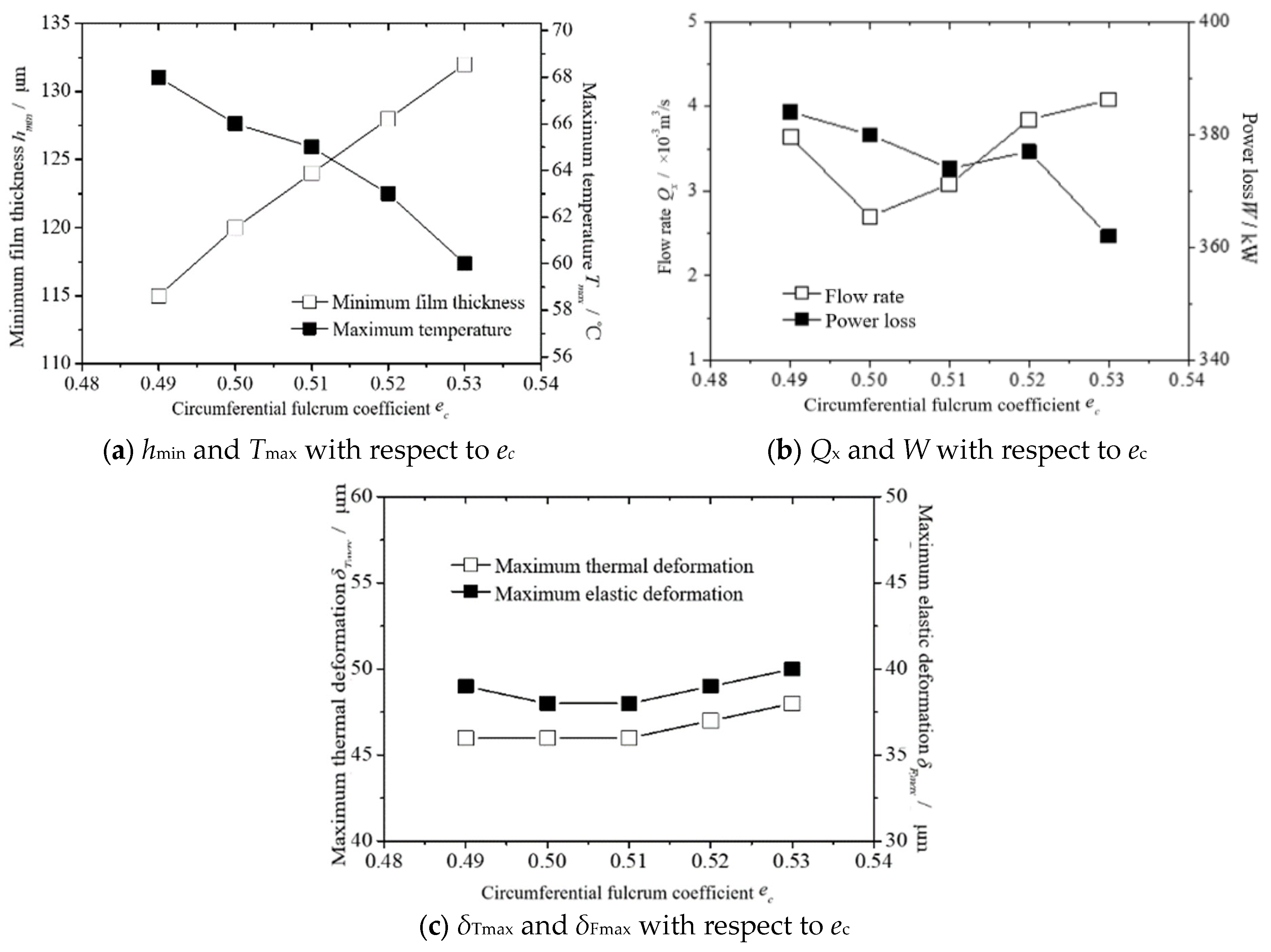
The thermoelastic lubrication performance of the thrust bearing is calculated when the circumferential fulcrum coefficient ec of the pad is 0.49~0.53. The calculation results are shown in Figure 7. Figure 7a shows the changes in hmin and Tmax at different ec values. It can be seen that hmin increases slightly with ec. When ec is 0.53, hmin increases by 15% compared with ec being 0.49, while Tmax decreases with an increase in ec. When ec is 0.53, Tmax decreases by 12% compared to when ec is 0.49. Figure 7b shows the changes in Qx and W at different ec. It can be seen that Qx decreases first and then increases with an increase in ec. The minimum value appears when ec is 0.53. The general trend of W decreases with an increase in ec. When ec is 0.53, W decreases by 6% compared to when ec is 0.49. Figure 7c shows the changes of δTmax and δFmax at different ec values. It can be seen that δTmax increases slightly with ec, while δFmax first decreases and then increases. The minimum value of δFmax appears when θo is 0.50 and 0.51, which are 38 μm. In summary, ec greatly influences hmin, Tmax, and Qx.

4.3. Influence of Tile Thickness on Lubrication Performance

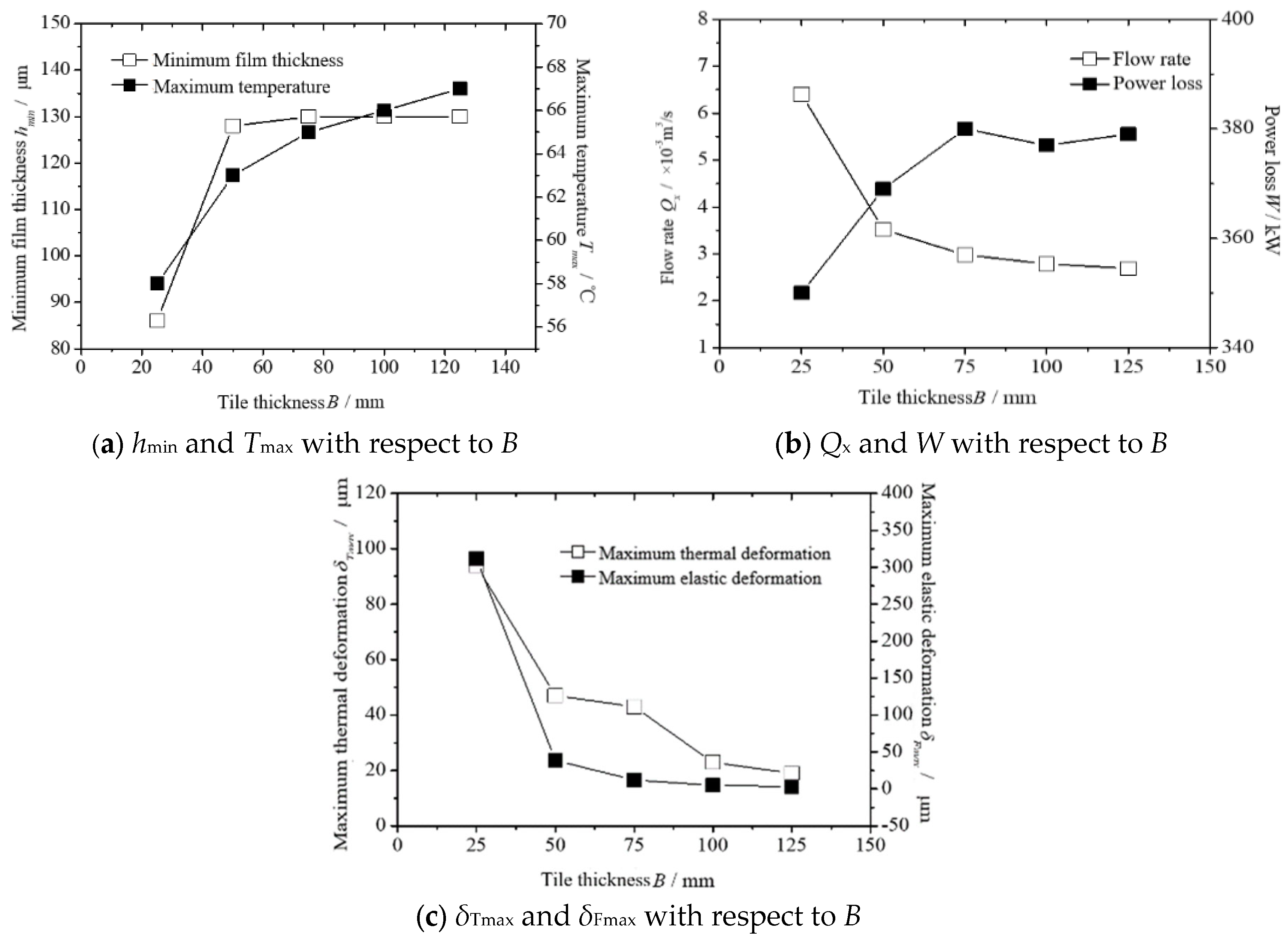
The hot bomb lubrication performance of the thrust bearing when the tile thickness B is 25–125 mm is calculated; the results are shown in Figure 8. Figure 8a shows hmin at different B and Tmax values. Parameters hmin and Tmax increase with B. When B reaches a certain value, hmin no longer changes. Parameters B and hmin change from 50 to 125 and 130, respectively. Parameter B is Tmax at 125 mm, and B is 25 mm, which is increased by 16%. Figure 8b Qx shows B and W. As B increases, Qx gradually decreases; B is Qx at 125 mm, B is 25 mm, down 58%, W increases with B, B is 125 mm, and B is 25 mm, up 8%. Figure 8c shows the value of δTmax at different B values; δTmax and δFmax decreased with increasing B, and B is the δTmax at 125 mm and δFmax 80% and 99% by 25 mm, respectively. The B value of the bearing tile is hmin, the total tile flow rate is Qx, the maximum thermal deformation amount is δTmax, and the maximum elastic deformation amount is δFmax. The influence becomes obvious, and the bearing performance is better when the B value exceeds 50 mm.

4.4. Influence of Tile Pad Elastic Modulus on Lubrication Performance

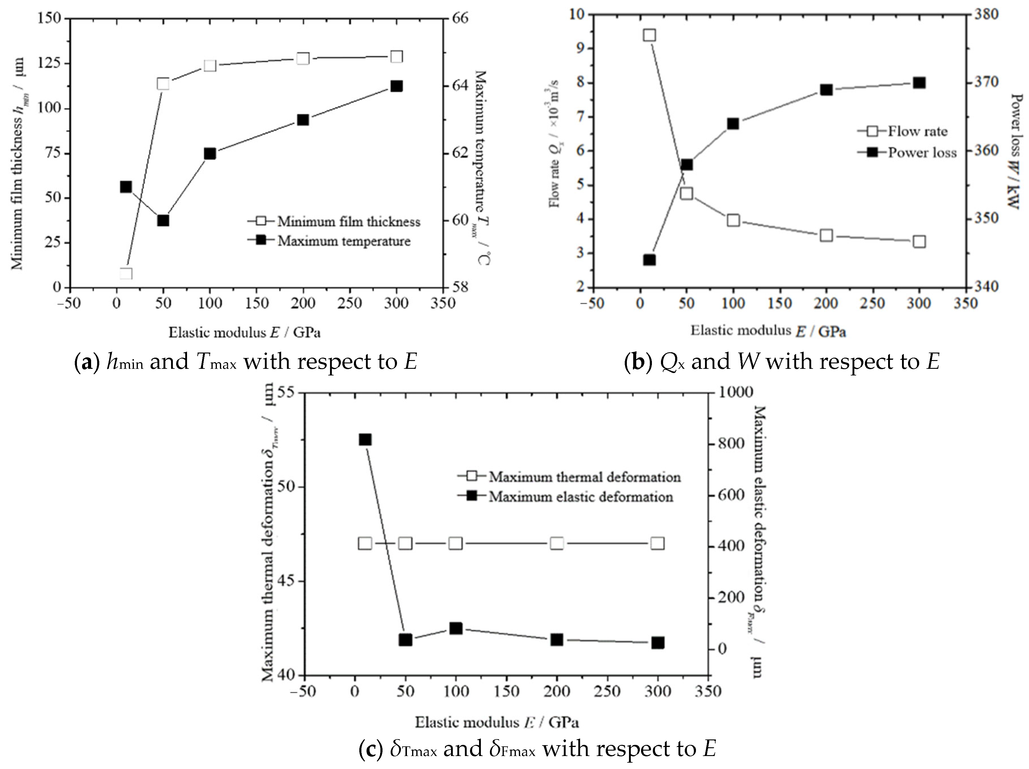
The thermal elastic lubrication performance of the thrust bearing with a different elastic modulus of the tile E is calculated. The value of E is 10–300 GPa. The calculation results are shown in Figure 9. Figure 9a represents hmin at different E and Tmax values. Parameter hmin increases with E. When E reaches a certain value, it remains constant. In contrast, the value of Tmax decreases as E increases. E is 50 GPa at the maximum level of Tmax. A minimum Tmax value of 60 °C is observed at E 300 GPa, i.e., an increase of only 5%. Figure 9b shows Qx with respect to E and W. As E increases, Qx gradually decreases. Parameter E is 300 GPa, and B decreases by 21% at 10 GPa, while W increases E by 300 GPa, i.e., by 8%. Figure 9c represents δTmax at different E and δFmax values. Parameter δTmax increases with E but remains unchanged at around 46.8 μm. In contrast, δFmax decreases as E increases; E reaches a certain value of δFmax. Parameter E becomes equal with δFmax at 300 GPa, i.e., about 780 μm less than when E is 10 GPa. Therefore, the influence is more obvious for the E value on the total tile flow being Qx and the maximum elastic deformation being δFmax. The value of E higher than 100 GPa is optimal.
According to the results of the above theoretical calculations, the minimum film thickness of the thrust-bearing hmin value is between 0 μm and 135 μm under the working conditions studied in this paper. The maximum temperature of the thrust-bearing Tmax value is between 56 °C and 70 °C. The flow rate of the thrust-bearing Qx value is between 2 × 10³ m−3/s and 10 × 103 m−3/s. The power consumption of thrust-bearing W value is between 340 kW and 400 kW. The maximum thermal deformation amount of thrust-bearing δTmax value is between 20 μm and 100 μm. The maximum elastic deformation amount of thrust-bearing δFmax value is between 0 μm and 150 μm. The above theoretical analysis data can guide the determination of the test plan before the thrust-bearing test, the selection of the sensor, and the determination of the installation position of the sensor.

5. Experimental Study on Take-Off Speed of Thrust Bearing of Canned Motor Pump

In the vertical rotor system of the canned motor pump, the thrust plate is completely separated from the tile surface. It forms a complete water film during the start-up process. The rotor speeds up to a certain speed, effectively lubricated and supported. This speed is the take-off speed, and the corresponding film thickness at this speed is the take-off film thickness.

5.1. Experimental Simulation of Take-Off Speed of Thrust Bearing

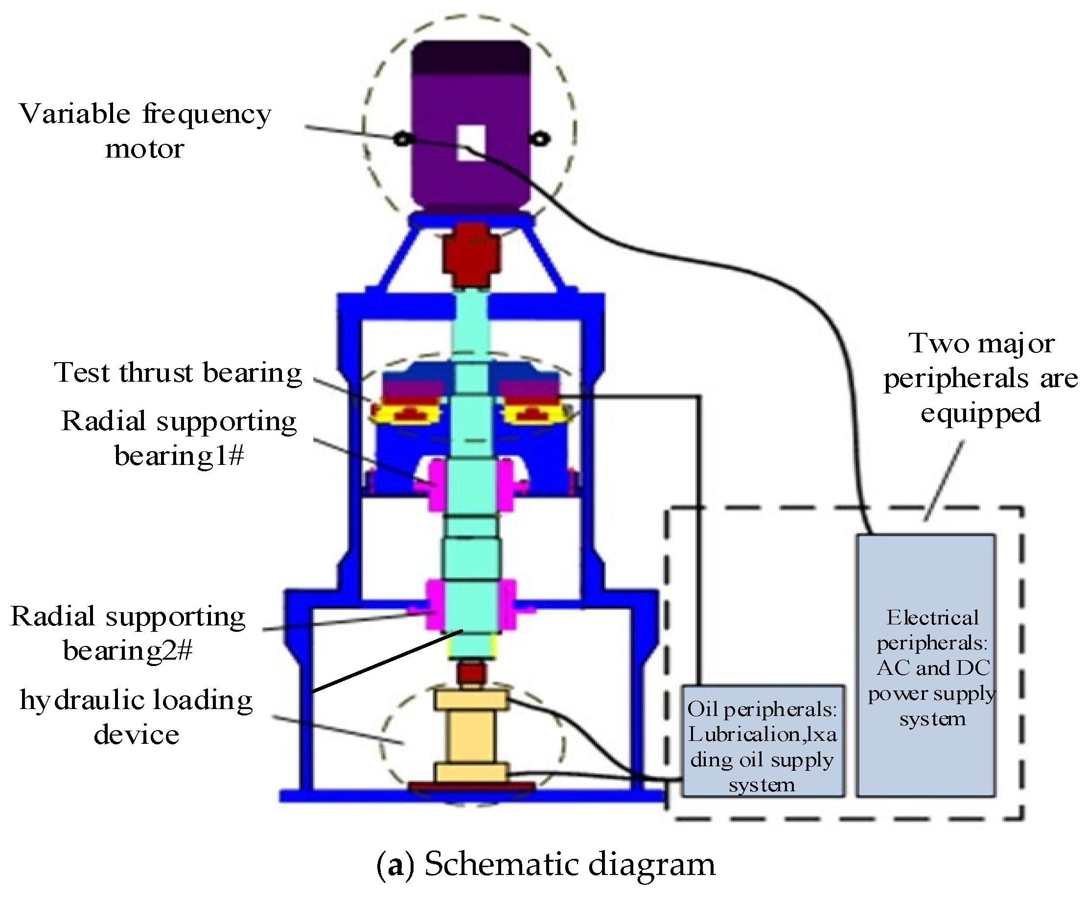
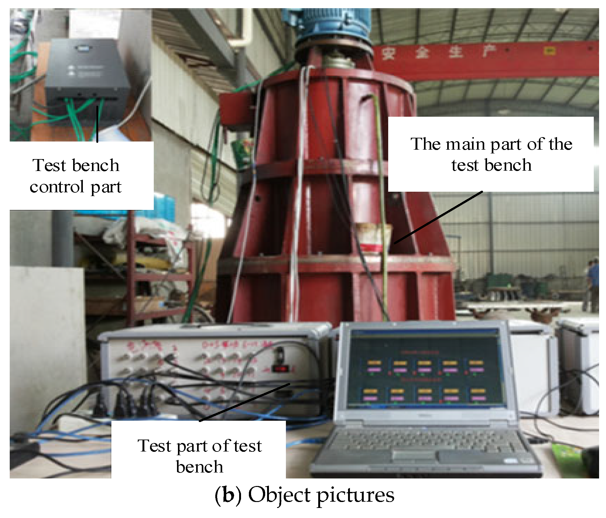
The test thrust bearing is manufactured according to the design parameters of the better bearing pad obtained from the previous calculation. The size of the test bearing is half of the actual design bearing size, and the size parameters of the bearing are shown in Table 3. The test is carried out on the vertical thrust-bearing test bench, which is designed and modified. The structural diagram of the test bench is shown in Figure 10. The thrust-bearing test bench comprises five parts: the main body, drive system, loading system, lubrication system, and test system. The rotor uses a stainless steel 1Cr18Ni9Ti thrust disc and stainless steel 2Cr13. The test bench is mainly divided into five parts: the main body of the test bench, the frequency conversion motor drive system, the loading device, the high-pressure oil station, and the lubrication and cooling system. The static pressure loading method is adopted. In order to cooperate with the low-speed start–stop test, the original high-speed low-torque motor is replaced with a high-torque frequency conversion speed regulation motor with a rated speed of 1000 r/min to ensure the starting torque. The size of the radial bearing shaft diameter is 156 mm, and the radial support bearing is a four-pad tilting pad bearing. The outer diameter of the thrust disc is 600 mm. Due to the reduction in the size, considering that the linear speed is the same as the actual size of the bearing, the maximum speed of the test motor is 3600 r/min. The maximum axial load of the hydraulic loading system is 10 tons. This test is the take-off speed test, and the speed of the test is 0~250 r/min.
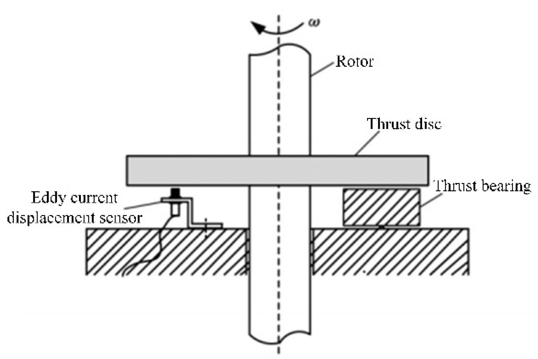
The eddy current sensor measures the displacement of the thrust disc relative to the bearing pad. Figure 11 shows the arrangement of the eddy current sensor. The sensor is arranged between two tiles and fixed on the thrust-bearing seat. The distance between the sensor’s end face and the thrust plate’s surface is 1.2 mm in a static state. When the rotor rotates, the thrust plate floats up due to the action of the liquid film. The sensor can measure the floating situation at the fulcrum.
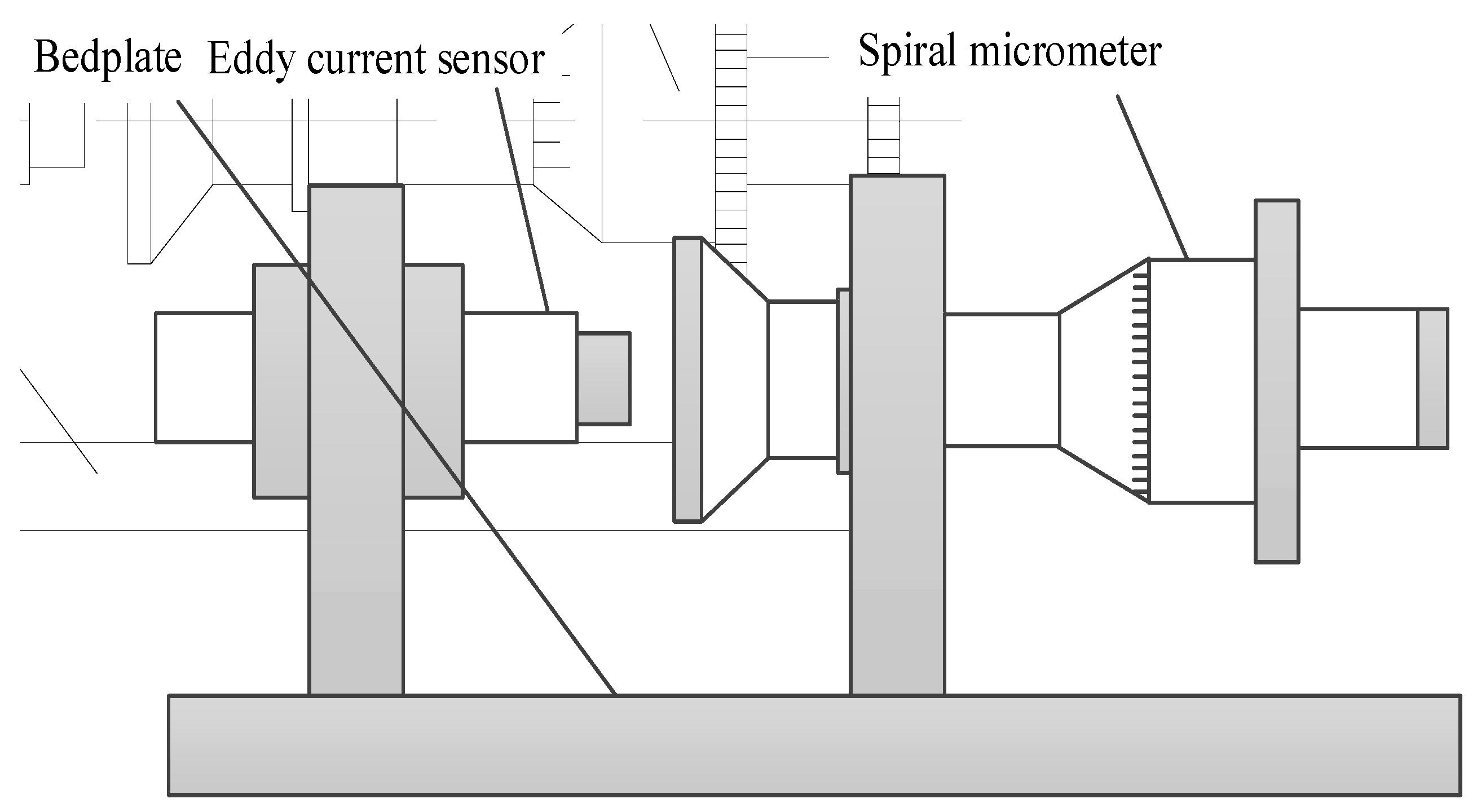
The schematic diagram of the calibration device is shown in Figure 12, including the base, the eddy current sensor, and the spiral micrometer. The core component is the spiral micrometer. The principle is that the distance between the eddy current sensor and the spiral micrometer is tested at the same time, and the distance measured by the spiral micrometer is used as the standard distance to calibrate the test signal of the sensor.
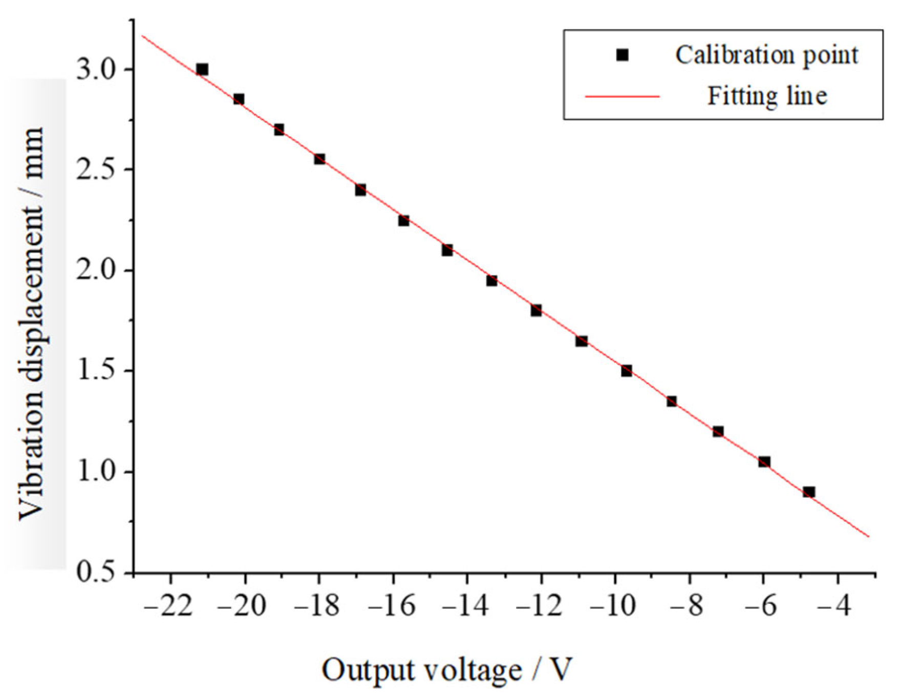
The test process is to divide the linear test range of the sensor into several segments on average, and test the nodes of each segment. It is considered that, at each node, the data measured by the spiral micrometer are the input value of the sensor, while the electrical signal measured by the eddy current sensor is the output value. The calibration curve of the sensor can be obtained by fitting the input and output values of the sensor by the least square method. The fitted static calibration line equation and the linear midpoint of the sensor are shown in Table 4. The x in the fitted curve equation represents the displacement, and U represents the output voltage value of the sensor. The calibration curve is shown in Figure 13.
The thickness of the take-off film is related to the friction pair of the contact surface between the bearing and the bearing. The complete water film must ensure that the film thickness is greater than the sum of the roughness of the two surfaces, as shown in Equation (24). In Equation (24), hf is the thickness of the take-off film, μm; s is the safety margin; and μ1 and μ2 are the surface roughness of the friction pair, μm.
h min h f = S   μ 1 + μ 2 .

5.2. Comparison of the Experimental Results with the Theoretical Calculations

Since the film thickness measured by the sensor is the film thickness at the fulcrum of load W, the film thickness at the theoretical fulcrum of full load W must be compared and analyzed. The following conclusions are drawn. The load applied in the test is 200 kN. The oil-lubricated bearing test is generally aimed at the static characteristics at high speed, and the start–stop condition is one of the main factors of water-lubricated graphite bearing wear. This paper mainly carries out the test for the static characteristics at start–stop. In this paper, the detection of the graphite bearing is the start–stop test, which mainly simulates the low-speed start–stop of nuclear main pump. The test process is as follows: (1) The test bench is powered on, the lubrication circuit is opened, and the test system is standby. (2) The test speed is slowly started from 0 r/min to 800 r/min within 5 min, and the temperature rise of bearing bush and the vibration of shaft system are tested during the start-up process. (3) The motor decelerates after 60 min of operation, and the speed is reduced to 0 r/min after 4 min of deceleration. The temperature rise in the graphite bearing, the axis trajectory of the rotor, and the wear of the graphite tile surface were measured. The wear amount was measured from the bearing bush after eight repeated start–stop processes.
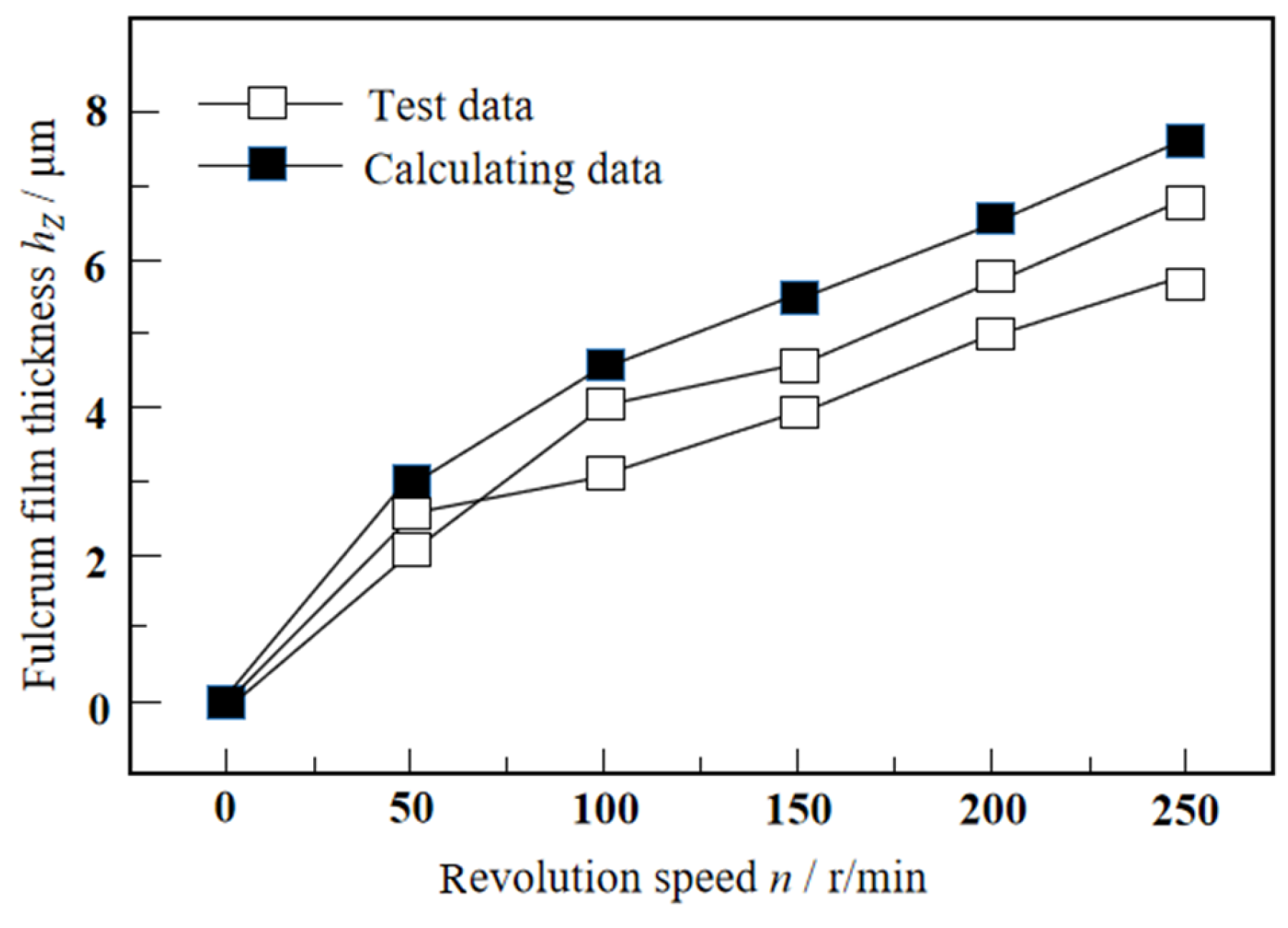
The test results are shown in Figure 14. The test represents a gradual acceleration process. The team’s film thickness of the bearing fulcrum at different speeds was tested. The test was repeated twice and compared with the theoretical calculation results. According to Figure 14, the thickness of the lubricating film of the thrust bearing increases gradually with the rotational speed. The theoretical calculation film thickness is slightly larger than the film thickness measured by the test. The reason may be that the bearing and the sensor had installation errors during the test. The error between the take-off speed (n = 180 r/min) measured in the test and the theoretical calculation result (n = 216 r/min) is 20%, which may be related to the roughness of the thrust disc and the bearing bush used in the test. On the other hand, the value of safety margin S will also affect the error between the two. The theoretical calculation and experimental results of this paper are compared with the research results in reference [23]. In reference [23], the theoretical and experimental research on the take-off speed of the thrust bearing is carried out. The size and working condition parameters of the bearing are similar to those in this paper. Reference [23] gives the theoretical calculation of the film thickness when the thrust-bearing fulcrum is at a speed of 0~300 r/min and the test result is between 0~5.5 μm. In this paper, when the rotational speed is 0~250 r/min, the thickness of the lubricating film at the bearing fulcrum obtained by theoretical calculation and the experimental result ranges from 0~7.5 μm. The comparison with reference [23] shows that the theoretical calculation and test data in this paper are reasonable.

6. Conclusions

In this paper, the calculation model and method of the lubrication performance of the thrust bearing, which consider the thermal–elastic deformation, are constructed based on the working characteristics of the main pump thrust of the nuclear power plant. The influence of the thrust-bearing design parameters on the lubrication performance of the canned motor pump is analyzed. The experimental study on the take-off speed of the thrust bearing of the canned motor pump was conducted. The conclusions are as follows:
1.
The tile wrap angle θo value has a significant influence on the minimum film thickness hmin, flow rate Qx, and power consumption W. The θo value has little effect on the maximum temperature Tmax, the maximum thermal deformation amount δTmax, and the maximum elastic deformation amount of δFmax. The tile fulcrum coefficient ec value has a great influence on the hmin and Tmax. The ec value has little effect on the Qx, Tmax, δTmax, and δFmax. The tile thickness B value has a great influence on the hmin, Tmax, Qx, and W. The B value has little effect on the Tmax and δTmax. The tile pad elastic modulus E value has a great influence on the Tmax, Qx, and δFmax. E value has little effect on the hmin, W, and δTmax.
2.
After considering the influence of the thermoelastic deformation, the thickness of the lubricating film of the thrust bearing decreases, the bearing capacity decreases, the temperature rise increases, the flow rate decreases, and the power consumption decreases. The thermal deformation has a great influence when the thrust-bearing pad is thick, while the elastic deformation has a great influence when the pad is thin.
3.
The error between the take-off speed (n = 180 r/min) measured in the test and the theoretical calculation result (n = 216 r/min) is 20%, which may be related to the roughness of the thrust disc and the bearing bush used in the test.
4.
The theoretical analysis results of this paper can guide the design of the thrust bearing of the nuclear main pump. The test method of this paper can guide the test work of this kind of thrust bearing. The test results of this paper can also guide the wear research of the thrust bearing in the start–stop stage.

Author Contributions

Conceptualization, Y.C., Y.Y. and Q.J.; methodology, H.G., M.Y. and Q.J.; software, Q.S. and X.M.; validation, Y.C., Y.Y. and Q.J.; formal analysis, H.G. and Q.J.; investigation, Y.C., M.Y. and Q.J.; resources, Q.J.; data curation, M.Y. and Y.Y. and Q.J.; writing—original draft preparation, Y.C., Y.Y. and Q.J.; writing—review and editing, M.Y. and Q.J.; visualization, Y.C., H.G.; supervision, Q.J.; project administration, Q.J.; funding acquisition, Q.J. All authors have read and agreed to the published version of the manuscript.

Funding

This research was funded by the Aviation Engine and gas turbine research grant number J2019-IV-0021-0089. The APC was funded by corresponding author Qian Jia.

Data Availability Statement

The original contributions presented in this study are included in the article. Further inquiries can be directed to the corresponding author.

Acknowledgments

This paper is supported by the Aviation Engine and gas turbine research fund (J2019-IV-0021-0089).

Conflicts of Interest

Authors Yanjun Cao, Yingjie Yu and Haiming Gang are employed by Zhengzhou Research Institute of Mechanical Engineering (ZRIME) Gearing Technology Co., Ltd. The remaining authors declare that they have no conflicts of interest.

References

  1. Jia, Q. Research on Manufacturing Process, Quality Inspection and Performance Test of Babbitt Alloy and Graphite Bearings. Ph.D. Thesis, Xi‘an Jiaotong University, Xi‘an, China, 2017. [Google Scholar]
  2. Holbert, K.E. A Review of Maritime Nuclear Reactor Systems. J. Nucl. Eng. 2025, 6, 5. [Google Scholar] [CrossRef]
  3. Wang, R. Lubrication Performance Calculation and Dynamic Characteristic Test of Tilting Pad Thrust Bearing Considering Fulcrum Deformation Under Axis Tilt. Ph.D. Thesis, Xi’an Jiaotong University, Xi‘an, China, 2021. [Google Scholar]
  4. Zhang, F.; Ouyang, W.; Xi, Y.; Yuan, X. Study on the Lubrication Performance and Take-off Speed of the Nuclear Main Pump Water Lubricated Bearing. Mach. Des. Res. 2017, 33, 87–92. [Google Scholar]
  5. Iliev, H. Failure analysis of hydro-generator thrust bearing. Wear 1999, 225–229, 913–917. [Google Scholar] [CrossRef]
  6. Zhang, X.; Zhu, C.; Zhang, J.; Zhang, C.; Duan, X.; Jing, J. Influence of Pad Inertia on Dynamic Characteristics of Water-lubricated Bearings of Nuclear Main Pump. Noise Vib. Control 2023, 43, 12–20. [Google Scholar]
  7. Jia, Q.; Yang, S.; Yang, J.; Zhu, Y.; Liu, Z. Study on the Influence of Design and Operating Parameters on the Performance of Guide Bearing of Nuclear Main Pump. Mach. Des. Res. 2022, 38, 80–85+89. [Google Scholar]
  8. Liu, X.; Tao, S.; Zhang, Y.; Zhou, X.; Li, P.; Su, X. Study on Bearing Performance of Nuclear Main Pump Bearing Upon Stop of Heavy-duty Idler. Fluid Mach. 2019, 47, 51–54+88. [Google Scholar]
  9. Liu, Z. Failure-Mode Dependent Reliability Analysis for the Thrust Bearing Positioning Mechanism of Nuclear Main Pump. Master’s Thesis, Dalian University of Technology, Dalian, China, 2022. [Google Scholar]
  10. Wang, W.; Zhang, Y.; Qi, S.; Zhao, H.; Cao, H. Process Method of Centering of Double—Direction Thrust Bearing by Nuclear Main Pump Motor Unit. Shanghai Medium Large Electr. Mach. 2021, 1, 31–33. [Google Scholar]
  11. Lei, M.; Li, M.; Guo, D. High-Performance Manufacturing Principle and Application of Thrust Bearings of Primary Pump in Nuclear Power Plant. China Nucl. Power 2020, 13, 592–598. [Google Scholar]
  12. Tang, Q.; Lai, X.; Chen, X.; Li, P.; Du, J.; Cheng, H. Effect of thrust pad geometric parameters on characteristics of thrust bearing oil system for nuclear coolant pump. J. Drain. Irrig. Mach. Eng. 2020, 38, 560–565. [Google Scholar]
  13. Xu, W.; Jia, Y.; Fan, Y.; Feng, X. Research on thrust bearing failure of million kilowatt shaft seal nuclear main pump. Pump Technol. 2020, 1, 1–4+7. [Google Scholar]
  14. Wang, W.; Li, M.; Cai, L.; Wu, Z.; Xu, J. Study on Self-lubricating Friction Pair of Thrust Bearing in Nuclear Main Pump. Large Electr. Mach. Hydraul. Turbine 2019, 3, 17–21+25. [Google Scholar]
  15. Li, Q.; Xie, Q.; Du, P.; Fei, D.; Li, X.; Li, B.; Liu, Z. Experimental study on scaled-down pads for nuclear main pump thrust bearing. Ann. Nucl. Energy 2024, 198, 110297. [Google Scholar] [CrossRef]
  16. Kumar, R.; Gopaliya, M.K.; Khan, H.; Azam, M.S.; Biswal, D.K. Analysis of thrust pad bearing under mixed-EHL regime considering combined effect of deterministic and stochastic surface roughness. J. Braz. Soc. Mech. Sci. Eng. 2023, 45, 559. [Google Scholar] [CrossRef]
  17. Cao, J.; Zhai, L.; Luo, Y.; Ahn, S.H.; Wang, Z.; Liu, Y. Transient thermo-elasto-hydrodynamic analysis of a bidirectional thrust bearing in start-up and shutdown processes. Eng. Comput. 2022, 39, 1511–1533. [Google Scholar] [CrossRef]
  18. Ma, H.; Liu, Z.; Yang, C.; Cheng, Q.; Zhao, Y. Research on the Support Performance of Internal Feedback Hydrostatic Thrust and Journal Bearing Considering Load Effect. Mathematics 2024, 12, 1367. [Google Scholar] [CrossRef]
  19. Yavelov, I.S.; Rochagov, A.V.; Zholobov, A.V. Study of the Performance of a Thrust Sliding Bearing in Startup and Rundown Regimes. J. Frict. Wear 2024, 44, 376–382. [Google Scholar] [CrossRef]
  20. Yuan, X.; Zhu, J.; Chen, Z.; Wang, H.; Zhang, C. A Three-Dimensional TEHD Model and an Optimum Surface Profile Design of Pivoted Pad Thrust Bearings with Large Dimensions. Tribol. Trans. 2003, 46, 153–160. [Google Scholar] [CrossRef]
  21. Lee, D.W.; Kim, K.W. Turbulent Lubrication Theory Using Algebraic Reynolds Stress Model in Finite Journal Bearings with Cavitation Boundary Conditions. JSME Int. J. Ser. II 1990, 33, 200–207. [Google Scholar] [CrossRef]
  22. Ng, C.W.; Pan, C.H.T. A Linearized Turbulent Lubrication Theory. Trans. ASME Ser. D 1965, 87, 675–688. [Google Scholar] [CrossRef]
  23. Wang, R.; Jia, Q.; Yuan, X.Y. Quantitative Research of Take-off Speeds and Wear of Graphite Water-lubricated Hydrodynamic Thrust Bearings. China Mech. Eng. 2021, 32, 269–274. [Google Scholar]
Figure 1. Schematic diagram of thrust-bearing structure.
Lubricants 13 00191 g001
Figure 2. Explosion diagram of thrust-bearing structure.
Lubricants 13 00191 g002
Figure 3. Tilting pad thrust-bearing equilibrium position and force.
Lubricants 13 00191 g003
Figure 4. Discharge of thrust-bearing pad.
Lubricants 13 00191 g004
Figure 5. Calculation process of thermal–elastohydrodynamic lubrication performance for thrust bearing.
Lubricants 13 00191 g005
Figure 6. Thermal elastohydrodynamic lubrication characteristics of thrust bearings at different θo.
Lubricants 13 00191 g006
Figure 7. Thermal elastohydrodynamic lubrication characteristics of thrust bearings under different loads.
Lubricants 13 00191 g007
Figure 8. Thermal elastohydrodynamic lubrication characteristics of thrust-bearing pads with different tile thickness.
Lubricants 13 00191 g008
Figure 9. Thermal elastohydrodynamic lubrication characteristics of thrust-bearing pads with different elastic modulus.
Lubricants 13 00191 g009
Figure 10. The structural diagram of the test bench.
Lubricants 13 00191 g010aLubricants 13 00191 g010b
Figure 11. Thrust-bearing take-off film thickness test schematic diagram.
Lubricants 13 00191 g011
Figure 12. Thrust-bearing calibration device schematic diagram.
Lubricants 13 00191 g012
Figure 13. Displacement sensor calibration point and fitting curve.
Lubricants 13 00191 g013
Figure 14. Theoretical calculation of oil film thickness under different speeds.
Lubricants 13 00191 g014
Table 1. Thrust-bearing working parameters.
Parameter Name/UnitParameter Values
Load: F/kNMaximum 1000
Speed, n/r/min0~1800
The oil supply temperature is H/mm40
Lubrication mediumThe VG 68 # lubricating oil
Table 2. Thrust bearing parameters of theoretical analysis.
Parameter Name/UnitParameter Values
Internal watt diameter, d/mm400
Outer diameter of tile, D/mm1000
The tile pad is wrapped in θo36
Radial fulcrum coefficient of tile0.5
Periferential fulcrum coefficient of tile0.52
Block thickness B/mm50
The tile elastic modulus200
Number of tile pads8
Table 3. Thrust bearing parameters of experimental study.
Parameter Name/UnitValue
Bearing bore diameter d/mm 200
Bearing outside diameter D/mm500
The central angle of tile pad θo36
Radial fulcrum coefficient0.5
Circumferential fulcrum coefficient0.52
Pad thickness B/mm50
Elastic modulus of pads200
Number of tiles8
Table 4. Static characteristics of eddy current sensor.
Linear Midpoint of Displacement (mm)Output Linear Midpoint (V)Equation of Curve-Fitting
1.61−10.5x = 0.27538 − 0.12684U
Disclaimer/Publisher’s Note: The statements, opinions and data contained in all publications are solely those of the individual author(s) and contributor(s) and not of MDPI and/or the editor(s). MDPI and/or the editor(s) disclaim responsibility for any injury to people or property resulting from any ideas, methods, instructions or products referred to in the content.