Article

Fabrication of a Composite Groove Array Surface with Gradient Wettability Which Delivers Enhanced Lubrication Performance

by
Tianrui Zhang
1,
Chenglong Liu
1,*,
Xinming Li
1,
Feng Guo
1 and
Kongmin Zhu
2
1
School of Mechanical and Automotive Engineering, Qingdao University of Technology, Qingdao 266520, China
2
Zhichuang Future Science and Technology Development Co., Ltd., Liaocheng 252600, China
*
Author to whom correspondence should be addressed.
Lubricants 2025, 13(5), 193; https://doi.org/10.3390/lubricants13050193
Submission received: 25 March 2025 / Revised: 12 April 2025 / Accepted: 18 April 2025 / Published: 23 April 2025

Abstract

:
A novel composite groove array surface was fabricated using femtosecond laser ablation technology to enhance self-replenishment capability. Initially, the driving efficiency of droplets on the composite groove array surface was tested using a high-speed droplet transportation system, characterizing the effect of this surface on lubricant backflow characteristics. Simultaneously, measurement of lubricating film thickness was utilized to explore the lubrication enhancement effect of the composite groove array surface on oil film formation under reciprocating motion. The multidimensional gradient wettability, engineered through the composite groove array surface, demonstrated excellent efficiency in lubricant replenishment within the lubrication track. Oil droplet transportation testing demonstrated that the composite groove array surface, which induced gradient wettability at the boundary, attained a maximum driving speed of 123.5 mm/s. This innovative design significantly reduced the barriers associated with lubricant backflow, particularly those induced by cavitation expansion during high-frequency reciprocating motion. Furthermore, the results demonstrated that the film-forming capabilities of this composite groove array surface were enhanced, thereby optimizing the overall lubrication performance.

1. Introduction

Although traditional surface modification technologies can improve the surface properties of materials, their applications remain constrained by intrinsic material characteristics. Specifically, hard coatings on flexible substrates are prone to interfacial delamination due to insufficient bonding strength [1], and chemical modification layers tend to degrade through mechanical wear during friction processes [2]. In contrast, surface texturing technology provides an innovative solution for significantly enhancing tribological performance by precisely engineering surface morphological characteristics to overcome these technical limitations [3,4,5,6,7,8,9,10,11]. With the rapid advancement of micromachining technologies, surface texturing has emerged as an effective strategy for optimizing the lubrication performance of friction pairs and enhancing load-bearing capacity [12,13,14,15]. Bayer et al. [16] found that the meniscus shapes in the contact zone can regulate the efficiency of lubrication grease replenishment, and the resulting capillary pressure promotes the transportation of grease into the contact zone. Sommers et al. [17] achieved directional droplet transportation control by fabricating tailored surface topographies on copper substrates via laser texturing technology, which induces surface tension gradient effects. Vlădesc et al. [18] investigated the use of laser processing technology for fabricating specific patterned surface textures on automotive piston-cylinder liner systems. Their study demonstrated that such surface texturing can effectively reduce friction and wear during reciprocating contact processes. Marian et al. [19] conducted both theoretical and experimental analyses on partially laser-textured thrust bearings. Their experimental results demonstrated that optimized surface texture designs can significantly improve a bearing’s lubrication performance, reduce the friction coefficient, and enhance load-carrying capacity. Vidyasagar et al. [20] laser-etched snakeskin-like texture patterns on the inner rings of deep-groove ball bearings. Their experimental results showed that such textures can enhance bearing lubrication efficiency and effectively improve the tribological performance of bearings. Tala-Ighil et al. [21] demonstrated that a 40% texture area ratio optimizes bearing performance, and delivers lower friction and higher load capacity compared with other ratios. Li et al. [22] demonstrated through computational simulations and experimental investigations that textured bearings exhibit superior lubrication and tribological performance. Liu et al. [23] fabricated a composite coating comprising microtextures and DLC/MoS₂ on titanium alloy substrates. Experimental results demonstrated that this coating exhibits superior tribological properties across varying temperatures and extended friction cycles.
However, designing textures within the contact zone can lead to disadvantages such as stress concentration [24]. Therefore, textures may be machined on both sides of the lubrication track along with a lubricant guiding design. Liu et al. [25] developed a functional surface with stepped wettability gradients by fabricating oil-transportation coatings on both sides of the lubrication track. Experimental results confirmed that this modified surface delivered excellent lubricant replenishment performance. Li et al. [26] improved the dynamic regulation capability of the lubricant pool through wettability gradient design. Liu et al. [27] achieved enhanced lubrication film effects in bearings by designing laser ablation microgrooves that provided directional driving of the lubricant. Zhang et al. [28] proposed a fishbone-like microtextured surface, which was strategically designed in noncontact areas, to achieve simultaneous directional droplet transport and enhance lubrication performance. Hirayama et al. [29] investigated the lubrication performance of surfaces featuring parallel grooves flanking the lubricating track. Liu et al. [30] proposed a wedge-shaped oleophilic groove with secondary structures on superoleophobic surfaces; this delivered the dual functionalities of directional droplet transport and lubricant retention while significantly enhancing tribological performance. Wu et al. [31,32] designed a biomimetic composite surface coating which delivered autonomous lubricant transport functionality. Their experimental results demonstrated that the surface significantly reduced churning friction and decreased temperature under high-speed operation. The above findings reveal that engineered surface textures effectively mitigate lubricant leakage in the bearing contact zone, consequently enhancing lubricating film thickness. Furthermore, surface engineering approaches incorporating coatings, textures, and other methodologies have proven effective in regulating lubricant flow, and represent significant advancements in lubrication technology.
In this paper, we address the issue of lubricant being squeezed out of the operating lubricant track and then finding it difficult to return under harsh conditions, and propose a method for lubrication enhancement. By enhancing the lubricant return flow, our aim in the present work was to improve the operational lifespan of the bearing. Specifically, a composite groove array surface, consisting of surface texture and an oleophobic coating prepared by femtosecond laser ablation, was employed. The strong driving capability for the lubricant of this surface enhances the lubricant backflow effect, thereby improving lubrication efficiency. The driving efficiency of this surface for lubricating oil was first investigated using a high-speed droplet transportation system. The surface was then applied to both sides of the lubrication track so that its effect on enhancing the film thickness of the lubrication track could be studied.

2. Materials and Methods

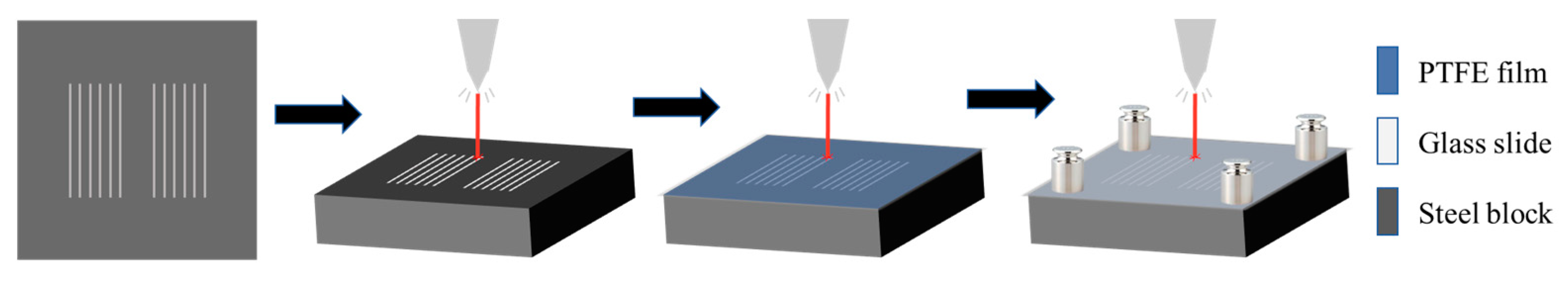
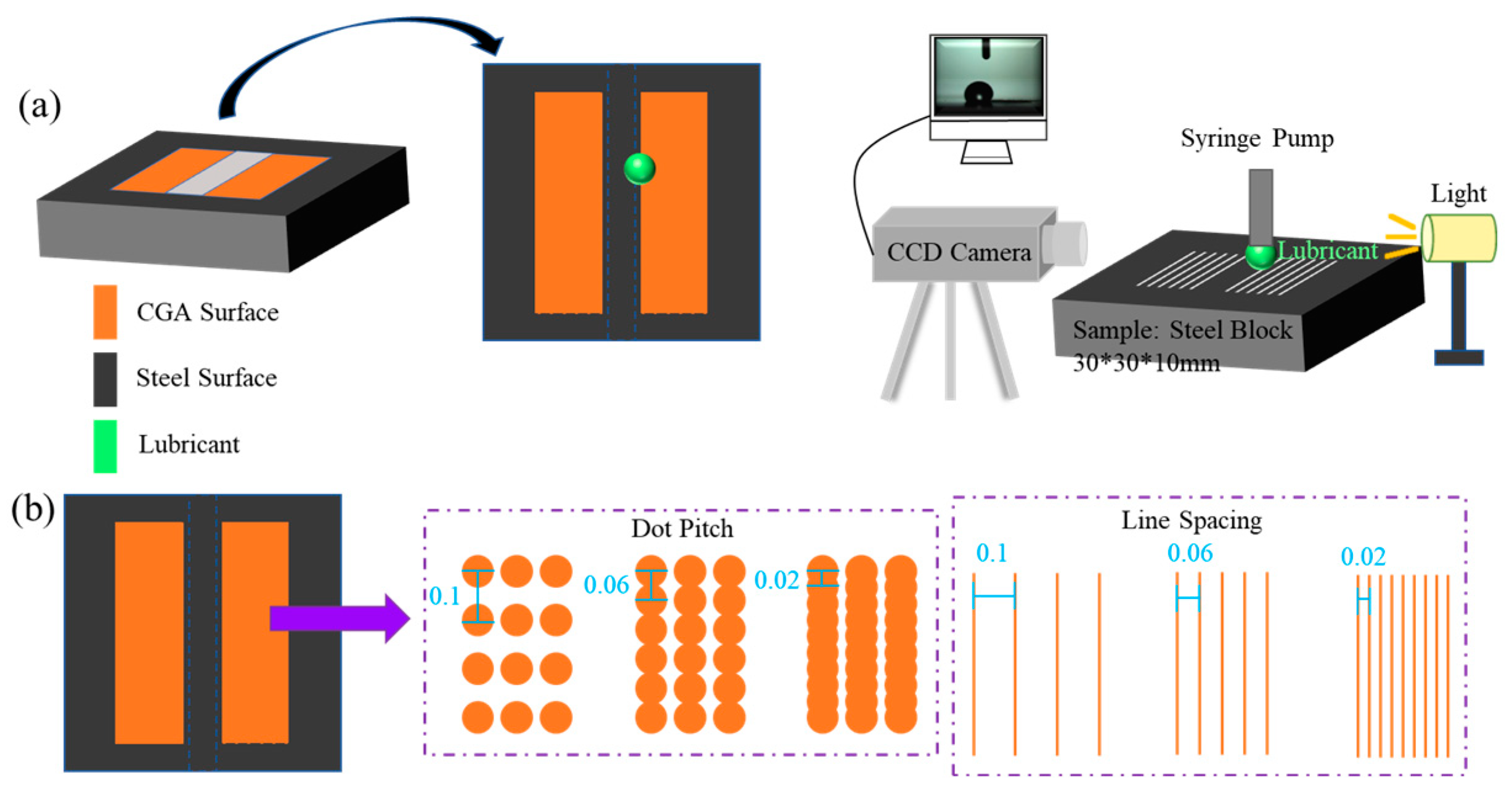
2.1. Sample Preparation

There is a noticeable surface tension gradient between an AF-coated surface and an ordinary surface [33]. A composite surface constructed by combining a textured array with a Polytetrafluoroethylene (PTFE) coating exhibits an even more pronounced surface tension gradient, compared with an ordinary surface. To verify the difference in surface tension between a PTFE composite surface and an ordinary surface, as well as its impact on droplet driving efficiency, the driving process of oil droplets at the boundary of the PTFE coating was observed using a high-speed droplet transportation system. The preparation process of the PTFE composite surface is illustrated in Figure 1. Before the experiment, the steel block surface was cleaned with petroleum ether and alcohol, allowed to air dry, then positioned using a fixture. The steel block surface was first subjected to laser ablation after positioning to create a groove array surface. Subsequently, a 0.03 mm thick PTFE film was uniformly overlaid on the steel surface. Following compression treatment, a second laser ablation enabled selective PTFE deposition within the surface textures, ultimately yielding a PTFE coating surface. The laser ablation parameters are shown in Table 1.
Using the processing method shown in Figure 1, three different shapes (Circle-like pattern array; Stripe-like pattern array; Grid-like pattern array) and varying densities (Dot Pitch; Line Spacing) of textures were fabricated using laser ablation. After processing, the surface textures and coating changes on the steel block were tested using a scanning electron microscope, as shown in Figure 2a. After the first laser ablation, LIPSSs (Laser-Induced Periodic Surface Structures) were observed in the textures of all shapes. After the second ablation, the coating in the surface micropores appeared as a hierarchical microstructure, indicating a composite groove array surface consisting of both textures and PTFE coating. The hierarchical microstructure distribution of the PTFE coating is conducive to the formation of an internal air cushion, allowing the liquid to achieve a Cassie contact state, thereby reducing the wetting state of the lubricant. As shown in Figure 2b, the contact angle of PEG200 on the PTFE coating surface was 151° in the direction parallel to the texture and 146° in the direction perpendicular to the texture, while on a normal surface it was 28°. This demonstrates that the rough air cushion layer structure of the PTFE surface significantly enhances its oleophobic properties.
Under reciprocating motion conditions, a composite groove array surface (linear groove array, PTFE coating (Polytetrafluoroethylene, Shenzhen Leshangjia Technology Co., Ltd., Shenzhen, China), and AF coating (Anti-fingerprint AF703, a combination of active silane groups and fluorine-modified organic groups, Shenzhen Aisike Lubrication Materials Co., Ltd., Shenzhen, China)) was utilized on both sides of the lubrication track to prepare a groove array surface constructed by multi-dimensional surface tension gradients, enhancing the self-replenishment capability of the lubrication track. We then explored the constraining effect on the bearing-oil separation pool under reciprocating motion. As shown in Figure 3, a 0.4 mm × 12.8 mm striped mask was placed over the cleaned glass block track surface, and the AF coating was uniformly applied to the steel block surface on both sides of the mask (heated at 85 °C for 35 min and naturally cooled to solidify), retaining a 0.4 mm width of the AF coating. The PTFE coating was laser-ablated onto the outer surface of the AF coating, with a width of 1 mm. When a PEG200 (0.1 μL) droplet was added to the prepared striped track, it was observed that the droplet was constrained within the track, an effect resulting from the combined action of the AF and PTFE surfaces. The AF coating surface has a relatively smooth texture (contact angle of 86°), while the PTFE coating surface features a microstructure with unevenness (contact angle of 146°). These two coatings form a multi-dimensional surface tension gradient with the ordinary surface, constructed by differences in surface roughness and surface tension. Driven by this surface tension gradient, the droplet exhibits a unidirectional transport effect. As shown in Figure 3, under the influence of the air cushion layer stored by the micro-rough surface, the slip performance of the oil droplet is enhanced, accelerating the movement of the lubricant from both sides of the track towards the center and reducing the oil churning resistance.

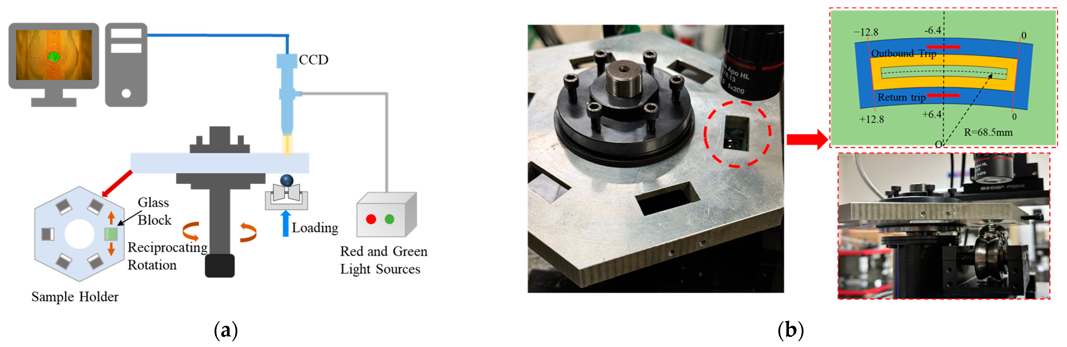
2.2. Measuring Equipment and Conditions

The mechanism by which composite groove array surfaces influence droplet driving efficiency was systematically investigated using a high-speed droplet transportation system. As shown in Figure 4a, the experiment was conducted on a single-side composite groove array region of the track to evaluate the oil droplet driving efficiency. A 7 μL PEG200 droplet was freely dropped from a height of 5 mm onto the boundary of the composite groove array. The droplet boundary diffusion process was captured in real-time by an image analysis system, and the surface driving efficiency was quantitatively calculated based on the diffusion distance. Figure 4b further illustrates how the influence of different texture shape densities on driving efficiency was explored by precisely controlling the dot spacing (0.02–0.10 mm) and line spacing (0.02–0.10 mm) to achieve a gradient design of texture morphology. Experimental results revealed that discrete dot arrays achieved optimal coverage at a dot spacing of 0.06 mm. When the dot spacing was reduced to 0.02 mm, the dot arrays gradually transitioned into continuous linear structures. Furthermore, when the line spacing was optimized to 0.02 mm, the linear textures evolved into quasi-continuous planar structures. This multi-scale morphological transformation significantly enhanced the surface driving performance.
The reciprocating motion module of a point-contact film thickness measurement tester was used to measure the oil film thickness and cavitation changes. Its structure and working principle are shown in Figure 5a. The glass block sample is fixed in a hexagonal fixture, and the reciprocating motion of the fixture is achieved through a linkage mechanism. When the reciprocating angle is controlled at 8.8° and the radius of rotation is 68.5 mm, the reciprocating stroke is 12.8 mm. A microscope and camera are used to magnify and capture the interference images of the contact area. A dichromatic interference intensity modulation approach [34] is employed to calculate the film thickness from the obtained interference images. The laser light source used in the experiment is a red-green dual-light source, with a red light wavelength of 640 nm and a green light wavelength of 525 nm. The reciprocating trajectory is shown in Figure 5b. Images taken at the midpoint of the entire stroke (±6.4 mm) are compared during the experiment. The linear velocity is highest at the midpoint of the reciprocating stroke, and a higher oil film thickness can be generated when the oil supply is sufficient. The film thickness measurement results are compared based on the film thickness at this point.
During the reciprocating rotation of the fixture, the steel ball rolls purely along with the glass block. The steel ball is loaded through a loading unit below it, and 0.1 μL of lubricating oil is evenly distributed on the motion track using a micro-injector. The system operates at a reciprocating frequency of 0.02 Hz under a 3 N load for 20 min to evenly distribute the lubricant. Once the lubricant pool on the track is uniformly distributed, the oil film measurement is conducted. The test load is 30 N, the test temperature is maintained at 22 ± 0.5 °C, and the humidity is 85 ± 5%. Each group of experiments is repeated three times, and each point is measured three times with an average value being taken.
The lubricants used for the investigation of droplet driving efficiency, film thickness measurement, and bearing friction torque measurement are listed in Table 2. These were Polyethylene glycol PEG200, Polyethylene glycol PEG500 (both from Wuxi Yatai Union Chemical Co., Ltd., Wuxi, China) and Polyester oil (from Shandong Hongxing Chemical Co., Ltd., Dongying, China), respectively. Among the three lubricants tested, PEG200 exhibited relatively weaker film-forming capability and was therefore only employed for flow velocity measurements, whereas both PEG500 and Polyester oil demonstrated superior film-forming performance, making them suitable for lubricating film thickness experiments.

3. Results and Discussion

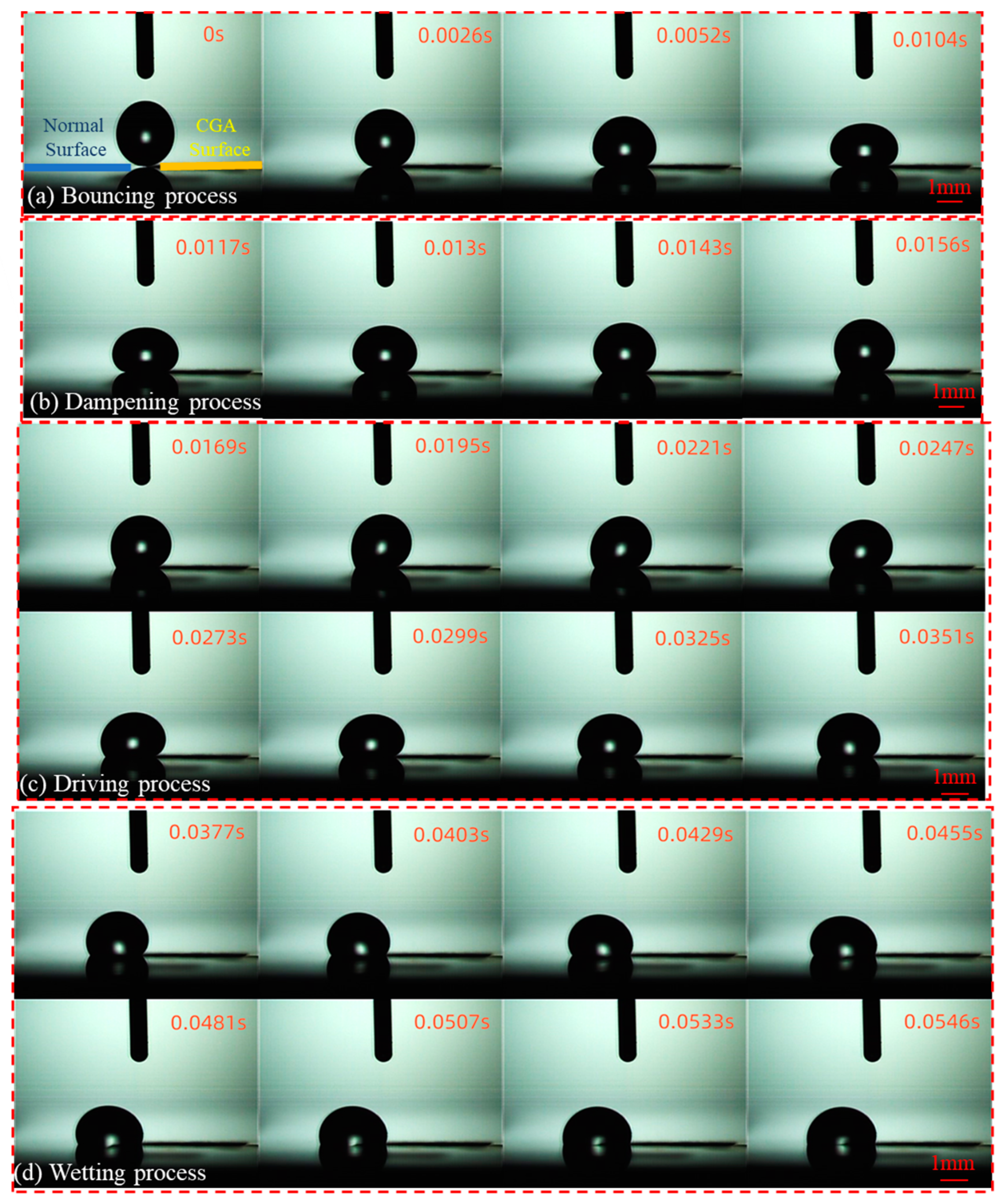
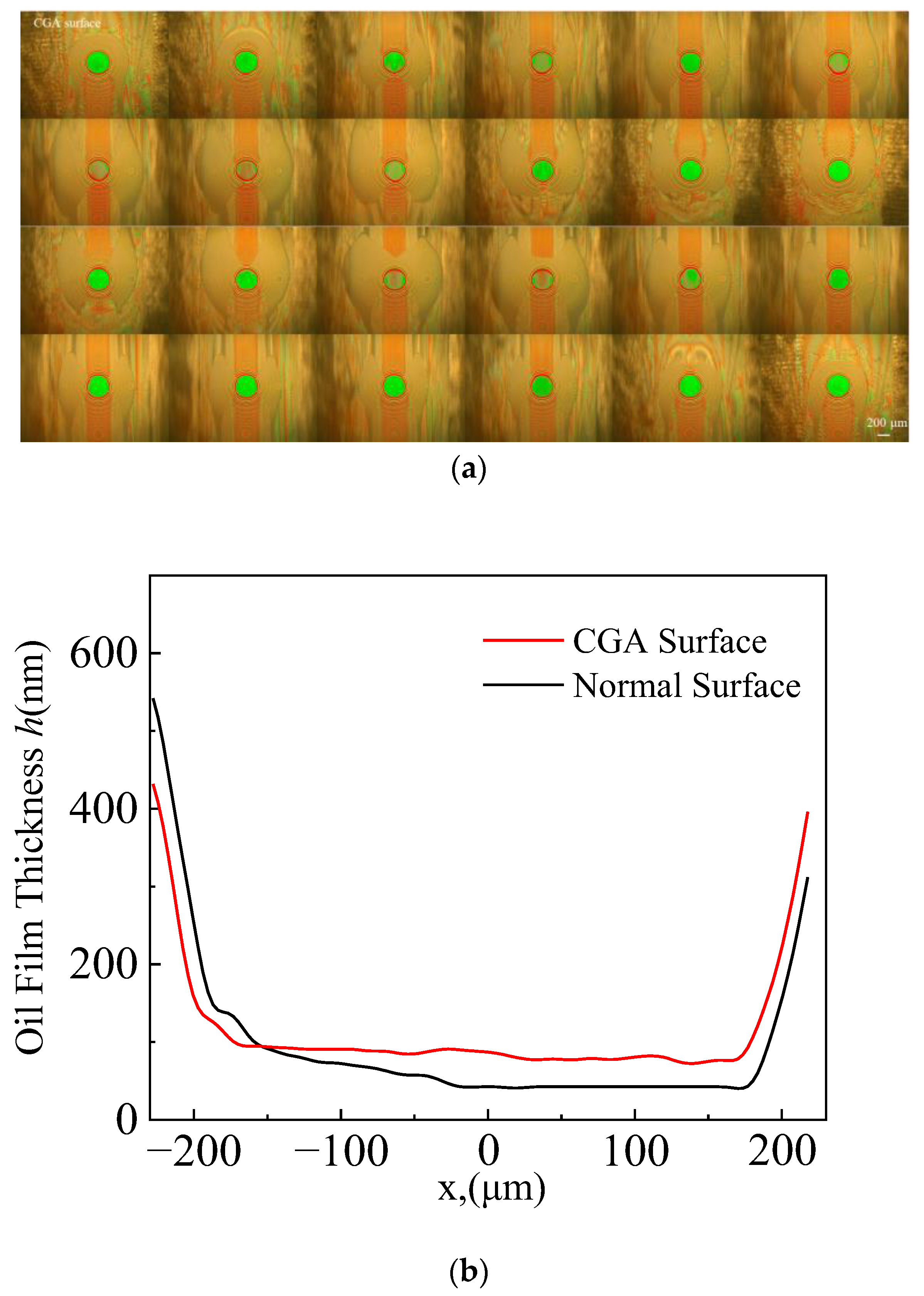
3.1. Effect of PTFE Coating Surface on the Driving Efficiency of Oil Droplets

A 7 μL droplet of PEG200 was dispensed onto the boundary between a PTFE coating surface and a normal surface, with the right side of the droplet on the PTFE coating surface (represented by a yellow line) and the left side on the normal surface (represented by a blue line). The motion of the droplet after impact was captured using a high-speed camera, revealing several distinct stages as shown in Figure 6: The first stage (a) is the bouncing process, occurring from 0 s to 0.0104 s. During this stage, the droplet transitions from a circular shape to an oval shape. This deformation is due to the combined effects of gravity and surface tension. Because the droplet falls from a low height, its kinetic energy is relatively small, resulting in elastic deformation only, without any rebound. The second stage (b) is the dampening process, occurring from 0.0117 s to 0.0156 s.
Although the droplet does not exhibit significant driven motion, there is a tendency for it to wet towards the left boundary because the left surface is a normal surface with a smaller contact angle. This process involves the interaction between the droplet and the surface, particularly the influence of surface tension gradients. Surface tension gradients can cause the droplet to spread or contract on the surface, affecting its shape and movement. The third stage (c) is the driving process, occurring from 0.0169 s to 0.0351 s. During this stage, the droplet is subjected to a surface tension gradient at the boundary, causing it to rapidly move from the oleophobic side to the oleophilic side. This movement is driven by the significant difference in surface tension, which causes the droplet to shift quickly. The final stage (d) is the wetting process, occurring from 0.0377 s to 0.0546 s. This is primarily determined by the droplet’s spreading behavior on the normal surface. The spreading of the droplet on the normal surface is essentially a result of interactions between liquid molecules, gas molecules, and solid surface molecules. The attraction between solid and liquid molecules pulls the wetting contact line outward, while the PTFE coating surface constrains the spreading, causing the droplet deposited at the boundary to migrate unidirectionally from the PTFE coating surface to the normal surface.

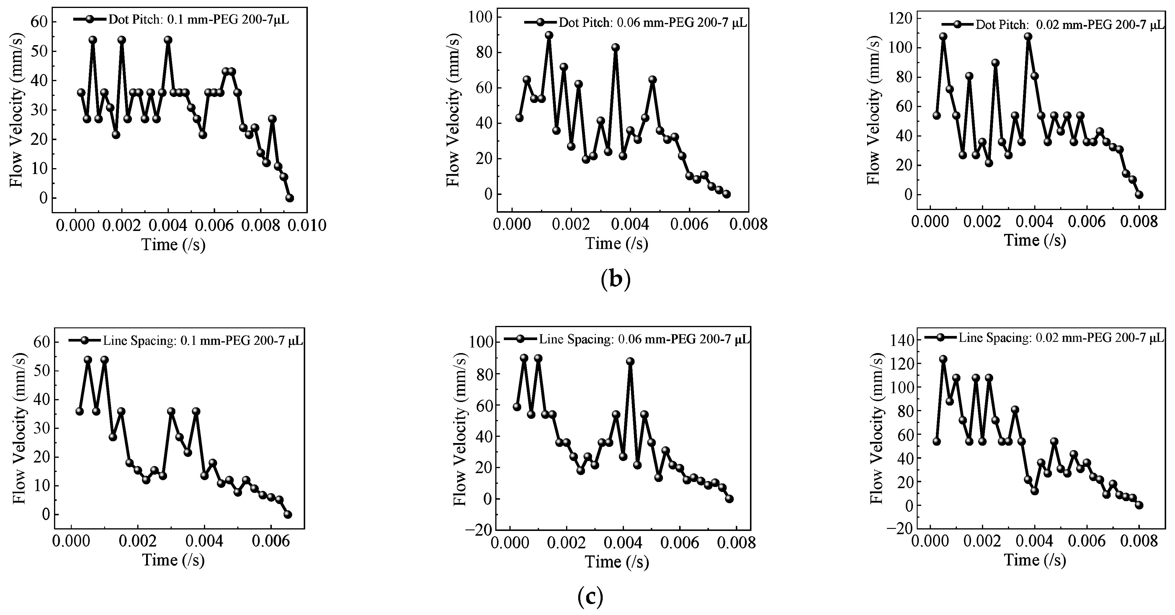
3.2. Lubricant-Driven Efficiency Analysis

In this study, we investigated the driving efficiency of lubricants on PTFE coating surfaces. PEG200 was selected as the lubricant, with precise control of lubricant volume (7 μL) and droplet falling height (5 mm) being maintained to ensure experimental repeatability. As shown in Figure 7, comparative analysis of lubricant driving efficiency between PTFE and pristine surfaces reveals that PTFE surfaces demonstrate significant performance advantages, far exceeding normal surfaces in driving efficiency. Among the four processes illustrated in Figure 6, the driving phase exhibits the highest velocity. In contrast, droplets on normal surfaces only undergo a free wetting process, resulting in substantially lower velocities. The AF coating surface exhibits unique transitional characteristics. Although its driving efficiency is slightly lower than that of the PTFE coating, it remains significantly superior to the normal surface.
To investigate the influence of different surface texture morphologies on lubricant driving efficiency, experiments were conducted under the conditions of a fixed droplet falling height of 5 mm and a lubricant volume of 7 μL. The experimental results demonstrated that the Grid-like pattern array exhibited optimal instantaneous driving performance, achieving a peak driving velocity of 103 mm/s, as shown in Figure 8a. In contrast, the Stripe-like pattern array demonstrated superior lubricant transportation stability, maintaining an average flow velocity of 78 ± 3 mm/s within the 0–0.035 s time period, higher than the 62 ± 5 mm/s observed for the Grid-like pattern array. Based on these distinct kinetic characteristics, the Stripe-like pattern array was selected for subsequent lubricating film thickness investigations. This phenomenon is primarily attributed to the unique flocculent distribution characteristics of the PTFE coating, which facilitates the formation of a stable internal air cushion on the surface, promoting the adoption of a Cassie contact state by the liquid, and thereby effectively reducing the wettability of the lubricant. Compared with the dot array, the filling effect of PTFE particles in the pores of the grid array is more ideal, forming a more continuous and uniform surface structure. This optimized surface morphology not only enhances the stability of the air cushion but also significantly reduces the contact area between the droplet and the solid surface, thereby decreasing frictional resistance.
Figure 8b illustrates the influence mechanisms of different dot densities on droplet driving efficiency. The experiments were conducted under strictly controlled conditions, with a constant droplet falling height of 5 mm and a PEG200 volume of 7 μL. The results demonstrated a significant increasing trend in droplet driving velocity as the dot spacing decreased from 0.1 mm to 0.02 mm. This enhancement is primarily attributed to two synergistic mechanisms: firstly, the higher dot density increases the deposition overlap rate of PTFE coating, forming a more continuous hydrophobic surface; secondly, when the dot spacing is reduced to 0.02 mm, the discrete dot-like structures gradually transition into continuous linear patterns, significantly enhancing the directional driving capability of the surface texture. During this process, the PTFE coating reduces droplet adhesion by lowering surface energy, while the linear texture guides droplet motion by providing directional capillary channels. The synergistic effect of these two factors enables the lubricant driving speed to reach a peak value of 107.69 mm/s.
Figure 8c illustrates the influence of different line densities on droplet driving efficiency. The experiments were conducted under controlled conditions, with a droplet falling height of 5 mm and a PEG200 volume of 7 μL. The results demonstrate a significant increasing trend in droplet driving velocity as the line spacing decreases from 0.1 mm to 0.02 mm, reaching a peak value of 123.5 mm/s on the CGA surface at 0.02 mm line spacing. With increasing line array density, the filling efficiency of PTFE particles in the micro-nano structural pores significantly improves, forming a more continuous and uniform surface coating structure. At a line spacing of 0.1 mm, the surface exhibits discrete linear features, where droplet motion primarily relies on the capillary action of individual lines. However, when the line spacing reduces to 0.02 mm, the discrete linear structures gradually transition into continuous planar patterns, significantly enhancing the continuity of surface gradients. During this process, the PTFE coating effectively reduces droplet adhesion by lowering surface energy, while the high-density linear textures guide droplet motion by enhancing capillary action and providing continuous directional transport channels.

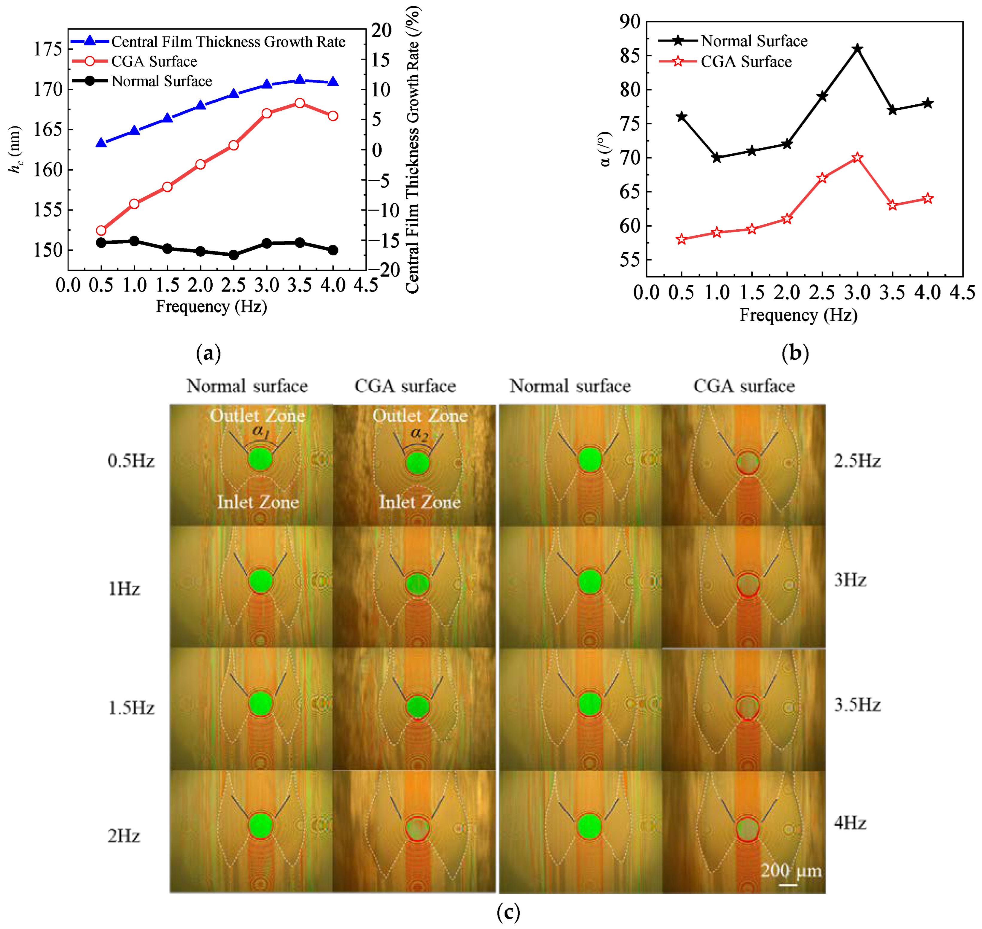
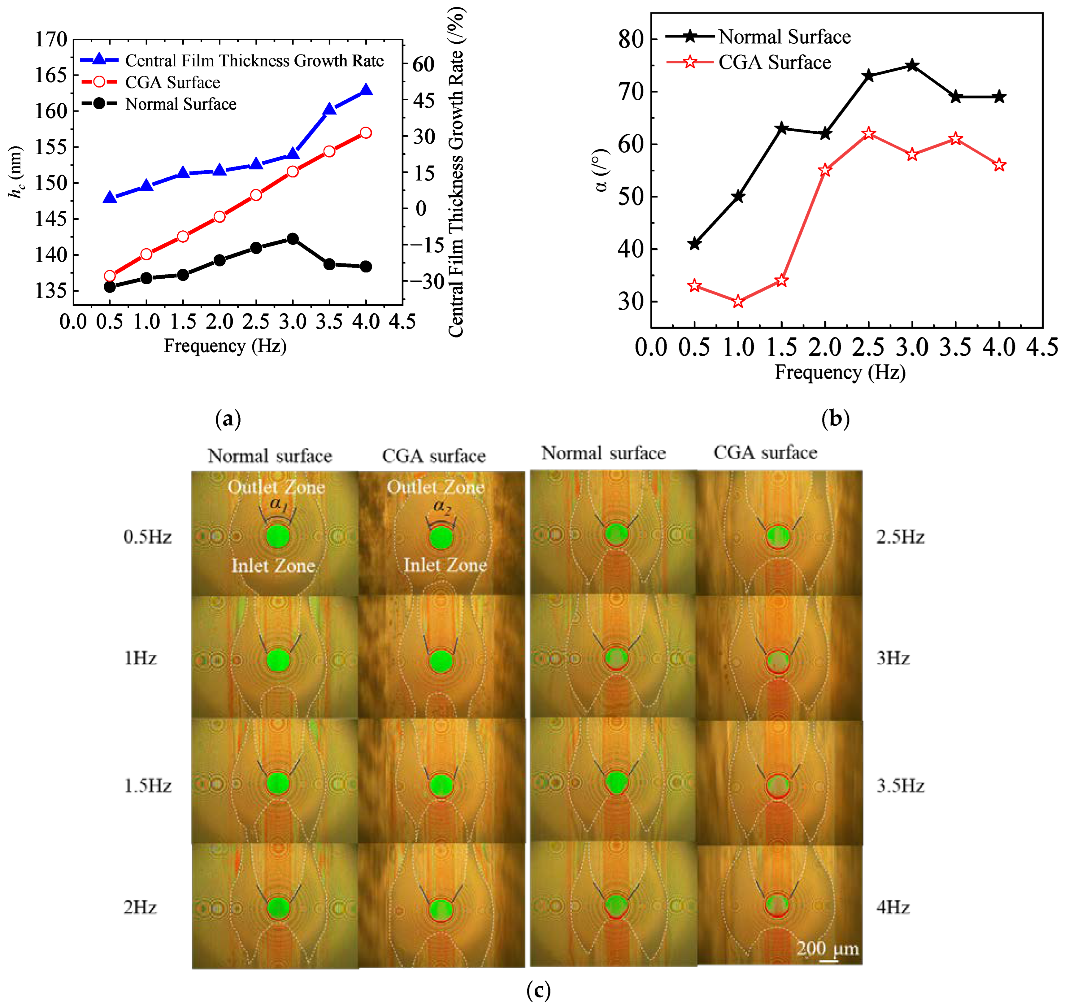
3.3. Investigation of Lubrication Enhancement

Next, we carried out a comparison of film thickness on the normal surface and the CGA surface. As shown in Figure 3, a reciprocating stroke track was prepared. On both sides of the lubrication track, an AF coating layer with a width of 0.4 mm was applied. Outside the AF coating, a PTFE coating with a width of 1 mm was prepared, forming a multidimensional wettability gradient surface to achieve better oil collection efficiency. The linear composite groove array surface was machined onto a glass block, and film thickness tests were conducted, with the film thickness at the midpoint of the reciprocating stroke taken as the measurement result. Figure 9a presents interferometric images of a polyester oil complete dynamic process under 2 Hz reciprocating motion on the CGA lubrication track, in which limited lubricant becomes confined to the central normal surface. After cavitation separation at the outlet of the contact zone, the lubricant is driven back to the center, forming an oil pool around the contact zone with a greater oil-starved distance and significantly reduced oil starvation. Figure 9b presents a comparative analysis of oil film thickness distribution at the stroke midpoint between conventional and CGA-engineered surfaces. By comparing the film thickness profiles at the center of the contact zone between the lubrication track constructed on the CGA surface and the original track, it can be seen that the oil pool expands after oil collection on the CGA surface, and the film thickness in the contact zone increases under the effect of centralized oil supply.
Figure 10a shows a comparison of the film thickness formed by 0.1 μL of polyester oil on the CGA and the normal surface under a load of 10 N. In the low-speed stage, the central film thickness of the CGA increases with speed, while the central film thickness of the normal surface gradually decreases. The rate of change in the central film thickness shows an upward trend. As can be easily seen from Figure 10b, the normal surface begins to experience severe oil starvation at a low speed of 1 Hz, and the contact area cannot be adequately replenished with lubricant, resulting in a lower oil film thickness. The oil film thickness on the CGA surface shows a decreasing trend at higher speeds. At this point, the cavitation at the exit of the contact area expands significantly under rapid reciprocating conditions, and the CGA cannot promptly drive all the oil reservoir back, increasing the degree of oil starvation and reducing the film thickness.
Figure 10b presents optical interferograms of oil films for polyester oil on different surfaces. The cavitation angle α at the outlet region of the lubricant reservoir is introduced, where α1 represents the angle on normal surfaces and α2 denotes the angle on CGA surfaces. As shown in Figure 10c, the reservoir angle α2 at the outlet region on CGA surfaces is significantly smaller than α1 on normal surfaces. Moreover, the lubricant reservoir at the outlet region of the composite groove surface exhibits a converging trend towards the central track. This phenomenon indicates that the lubricant is constrained by the CGA surfaces on both sides, with additional oil supply from the sides leading to increased film thickness and suppressed cavitation zone expansion. The multidimensional surface tension gradient, formed by the combined effects of surface tension and roughness variations, effectively regulates lubricant flow and distribution. Under high-speed conditions, this mechanism reduces cavitation zone expansion, thereby enhancing lubrication efficiency.
Figure 11a compares the oil film thickness distribution characteristics of 0.1 μL PEG500 on CGA surfaces and pristine surfaces under a 10 N load. During the low-speed phase, the central film thickness of the CGA surface increases with speed, while that of the pristine surface gradually decreases, showing significant differences in the rate of central film thickness change. As shown in Figure 11b, at 0.5 Hz, the bilateral structure of the CGA surface effectively promotes lubricant backflow, significantly suppressing cavitation. In contrast, the pristine surface exhibits noticeable oil starvation at a low speed of 1.5 Hz, with insufficient lubricant replenishment in the contact zone leading to a marked reduction in film thickness. Notably, under high-speed conditions, the CGA surface maintains stable film thickness through effective lubricant backflow, benefiting from the synergistic effects of multi-dimensional wettability gradients. Conversely, the pristine surface, lacking an effective backflow mechanism, experiences aggravated oil starvation and continuous film thickness reduction. To further analyze this phenomenon, the study introduces the cavitation angle α at the outlet region of the lubricant reservoir as an evaluation metric, where α1 represents the angle on pristine surfaces and α2 denotes the angle on CGA surfaces. As illustrated in Figure 11c, the reservoir angle α2 at the CGA surface outlet is significantly smaller than α1 on the pristine surface, with the composite groove surface outlet showing a distinct centripetal convergence trend. This characteristic indicates that the lubricant, constrained by the bilateral CGA surfaces, increases film thickness through lateral replenishment mechanisms, effectively inhibiting cavitation zone expansion. The multi-dimensional surface tension gradient, constructed based on surface tension and roughness variations, enables precise control of lubricant flow and distribution, significantly reducing cavitation expansion under high-speed conditions and thereby enhancing lubrication efficiency.

4. Conclusions

(1) In this paper, we propose a composite groove array (CGA) surface composed of an AF oleophobic coating, PTFE coating and multi-dimensional surface micro-textures. A multi-stepped wettability was prepared by the CGA surface which could provide higher driving force. By constructing this composite architecture on both sides of the contact area, remarkable fluid directional guidance effects were achieved, and superior lubrication enhancement performance demonstrated, under starved lubrication conditions.
(2) In the flow velocity tests conducted on composite groove array surfaces made of PTFE coating and groove array surface, the CGA surface exhibited remarkable lubricant transport capabilities compared with traditional smooth surfaces, with a maximum driving speed for PEG200 of 123.5 mm/s.
(3) The CGA surfaces on both sides of the contact area enhanced the self-replenishment capability of the lubrication track, effectively suppressing the side leakage of lubricant at the contact area. Under conditions of limited oil supply, the multidimensional wettability gradient demonstrated remarkable lubrication enhancement effects.

Author Contributions

Conceptualization, C.L.; Methodology, C.L., X.L., F.G. and K.Z.; Formal analysis, F.G.; Data curation, T.Z.; Writing—original draft, T.Z. and C.L.; Writing—review & editing, X.L. and F.G.; Supervision, K.Z. All authors have read and agreed to the published version of the manuscript.

Funding

This research was funded by the National Natural Science Foundation of China (Grant Nos. 52205201, 52175173), the Natural Science Foundation of Shandong Province (Grant No. ZR2022QE027), and Shandong Bearing Intelligent Manufacturing Innovation and Entrepreneurship Community (Grant No. gjgxjs002). The Article Processing Charge (APC) was funded by [Grant Nos. 52205201 and gjgxjs002].

Data Availability Statement

The original contributions presented in this study are included in the article. Further inquiries can be directed to the corresponding author.

Conflicts of Interest

Author Kongmin Zhu was employed by the company Zhichuang Future Science and Technology Development Co., Ltd. The remaining authors declare that the research was conducted in the absence of any commercial or financial relationships that could be construed as a potential conflict of interest.

References

  1. Bull, S.J.; Rickerby, D. Failure modes in scratch adhesion testing: Some observations. In Surface Modification Technologies III; CRC Press: Boca Raton, FL, USA, 1989; pp. 153–169. [Google Scholar]
  2. Tsukruk, V.V.; Everson, M.P.; Lander, L.M.; Brittain, W.J. Nanotribological properties of composite molecular films: C60 anchored to a self-assembled monolayer. Langmuir 1996, 12, 3905–3911. [Google Scholar] [CrossRef]
  3. Etsion, I. Improving tribological performance of mechanical components by laser surface texturing. Tribol. Lett. 2004, 17, 733–737. [Google Scholar] [CrossRef]
  4. Kataoka, D.E.; Troian, S.M. Patterning liquid flow on the microscopic scale. Nature 1999, 402, 794–797. [Google Scholar] [CrossRef]
  5. Etsion, I.; Halperin, G. A laser surface textured hydrostatic mechanical seal. Tribol. Trans. 2002, 45, 430–434. [Google Scholar] [CrossRef]
  6. He, Y.; Wang, L.; Wu, T.; Wu, Z.; Chen, Y.; Yin, K. Facile fabrication of hierarchical textures for substrate-independent and durable superhydrophobic surfaces. Nanoscale 2022, 14, 9392–9400. [Google Scholar] [CrossRef]
  7. Bartkowiak, T.; Peta, K.; Królczyk, J.B.; Niesłony, P.; Bogdan-Chudy, M.; Przeszłowski, Ł.; Trych-Wildner, A.; Wojciechowska, N.; Królczyk, G.M.; Wieczorowski, M. Wetting properties of polymer additively manufactured surfaces–Multiscale and multi-technique study into the surface-measurement-function interactions. Tribol. Int. 2025, 202, 110394. [Google Scholar] [CrossRef]
  8. Zhu, L.; Ni, C.; Yang, Z.; Liu, C. Investigations of micro-textured surface generation mechanism and tribological properties in ultrasonic vibration-assisted milling of Ti–6Al–4V. Precis. Eng. 2019, 57, 229–243. [Google Scholar] [CrossRef]
  9. Yao, X.; Guo, Y.; Gao, Y.; Hossain, K.R.; Ji, Z.; Lu, Z.; Wang, X.; Wang, Q.; Zhou, F. Additive manufacturing patterned self-lubricating polyimide surfaces. Tribol. Int. 2023, 189, 108972. [Google Scholar] [CrossRef]
  10. Du, G.; Guo, J.; Wang, J.; Bian, D.; Zhang, X. Tribological behavior of 3D printed nanofluid reinforced photosensitive self-lubricating polymer materials. Addit. Manuf. 2024, 80, 103959. [Google Scholar] [CrossRef]
  11. Xing, Y.; Luo, C.; Zhu, M.; Zhao, Y.; Ehmann, K.; Wu, Z.; Liu, L. Assessment of self-lubricating coated cutting tools fabricated by laser additive manufacturing technology for friction-reduction. J. Mater. Process. Technol. 2023, 318, 118010. [Google Scholar] [CrossRef]
  12. Willis, E. Surface finish in relation to cylinder liners. Wear 1986, 109, 351–366. [Google Scholar] [CrossRef]
  13. Xing, Y.; Luo, C.; Wan, Y.; Huang, P.; Wu, Z.; Zhang, K. Formation of bionic surface textures composed by microchannels using nanosecond laser on Si3N4-based ceramics. Ceram. Int. 2021, 47, 12768–12779. [Google Scholar] [CrossRef]
  14. Etsion, I. State of the art in laser surface texturing. J. Tribol. 2005, 127, 248–253. [Google Scholar] [CrossRef]
  15. Khani, S.; Haghighi, S.S.; Razfar, M.R.; Farahnakian, M. Improvement of thread turning process using micro-hole textured solid-lubricant embedded tools. Proc. Inst. Mech. Eng. Part B J. Eng. Manuf. 2021, 235, 1727–1738. [Google Scholar] [CrossRef]
  16. Bayer, G.; Wandel, S.; Ayromlou, A.; Bader, N.; Poll, G. Influence of the meniscus on wear in grease-lubricated oscillating rolling contacts. Tribol. Int. 2024, 197, 109771. [Google Scholar] [CrossRef]
  17. Sommers, A.D.; Brest, T.J.; Eid, K.F. Topography-based surface tension gradients to facilitate water droplet movement on laser-etched copper substrates. Langmuir 2013, 29, 12043–12050. [Google Scholar] [CrossRef]
  18. Vlădescu, S.-C.; Olver, A.V.; Pegg, I.G.; Reddyhoff, T. Combined friction and wear reduction in a reciprocating contact through laser surface texturing. Wear 2016, 358, 51–61. [Google Scholar] [CrossRef]
  19. Marian, V.G.; Gabriel, D.; Knoll, G.; Filippone, S. Theoretical and experimental analysis of a laser textured thrust bearing. Tribol. Lett. 2011, 44, 335–343. [Google Scholar] [CrossRef]
  20. Vidyasagar, K.E.C.; Pandey, R.K.; Kalyanasundaram, D. Improvement of deep groove ball bearing’s performance using a bionic textured inner race. J. Bionic Eng. 2021, 18, 974–990. [Google Scholar] [CrossRef]
  21. Tala-Ighil, N.; Fillon, M.; Maspeyrot, P. Effect of textured area on the performances of a hydrodynamic journal bearing. Tribol. Int. 2011, 44, 211–219. [Google Scholar] [CrossRef]
  22. Li, Z.; Yin, S.; Zhang, Q.; Zhang, X.; Zhang, H. Analysis of Lubrication Characteristics and Friction Test of Texture Topography of Angular Contact Ball Bearing Based on Computational Fluid Dynamics. Lubricants 2025, 13, 41. [Google Scholar] [CrossRef]
  23. Liu, K.; Ding, Q.; Peng, H.; Guan, K.; Xi, X.; Kong, N.; Liao, M. Tribological Properties of Multilayer DLC/MoS2 Nanocomposite Coatings on Microtextured Titanium Alloy Surfaces. Lubricants 2024, 12, 374. [Google Scholar] [CrossRef]
  24. Gachot, C.; Rosenkranz, A.; Hsu, S.M.; Costa, H.L. A critical assessment of surface texturing for friction and wear improvement. Wear 2017, 372, 21–41. [Google Scholar] [CrossRef]
  25. Liu, C.L.; Guo, F.; Wong, P.L.; Li, X.M. Tribological behaviour of surfaces with stepped wettability under limited lubricant supply. Tribol. Int. 2020, 141, 105880. [Google Scholar] [CrossRef]
  26. Li, X.M.; Guo, F.; Wong, P.L.; Zhao, Y. Regulation of lubricant supply by wettability gradient in rolling EHL contacts. Tribol. Int. 2018, 120, 565–574. [Google Scholar] [CrossRef]
  27. Liu, C.; Guo, F.; Wong, P.; Li, X. Laser pattern-induced unidirectional lubricant flow for lubrication track replenishment. Friction 2022, 10, 1234–1244. [Google Scholar] [CrossRef]
  28. Zhang, H.; Dai, S.; Liu, Y.; Zhu, Y.; Xu, Y.; Li, B.; Dong, G. Fishbone-like micro-textured surface for unidirectional spreading of droplets and lubricity improvement. Tribol. Int. 2024, 198, 109932. [Google Scholar] [CrossRef]
  29. Hirayama, T.; Ikeda, M.; Suzuki, T.; Matsuoka, T.; Sawada, H.; Kawahara, K. Effect of nanotexturing on increase in elastohydrodynamic lubrication oil film thickness. J. Tribol. 2014, 136, 031501. [Google Scholar] [CrossRef]
  30. Liu, Y.; Chen, J.; Zhang, H.; Gou, H.; Dong, G. Wedge-shaped lyophilic pattern on superlyophobic surface for unidirectional liquid guidance and lubrication enhancement. Tribol. Int. 2024, 194, 109552. [Google Scholar] [CrossRef]
  31. Wu, C.; Yang, K.; Ni, J.; Lu, S.; Yao, L.; Li, X. Investigations for vibration and friction torque behaviors of thrust ball bearing with self-driven textured guiding surface. Friction 2023, 11, 894–910. [Google Scholar] [CrossRef]
  32. Wu, C.; Zheng, C.; Teal, P.D.; Han, Y.; Xu, J.; Li, X. Investigation on the performances of thrust ball bearing with a novel oil self-transportation biomimetic composite guiding surface. Alex. Eng. J. 2025, 110, 579–594. [Google Scholar] [CrossRef]
  33. Liu, C.; Guo, F.; Li, X.; Wong, P.; Poll, G.; Liu, M. Enhancement of lubricant replenishment under limited lubricant supply in rolling bearings. Tribol. Lett. 2024, 72, 6. [Google Scholar] [CrossRef]
  34. Liu, H.C.; Guo, F.; Guo, L.; Wong, P.L. A dichromatic interference intensity modulation approach to measurement of lubricating film thickness. Tribol. Lett. 2015, 58, 15. [Google Scholar] [CrossRef]
Figure 1. Textured surface process on steel block.
Lubricants 13 00193 g001
Figure 2. Microscopic morphology of PTFE coating surface and contact angles on different surfaces. (a) Microscopic morphology characterization of laser ablation textures with different shapes; (b) Contact angles of PEG200 on different surfaces.
Lubricants 13 00193 g002
Figure 3. Lubrication tracks fabricated by CGA surfaces.
Lubricants 13 00193 g003
Figure 4. High-speed droplet transportation system and parameters of PTFE coating surface. (a) Schematic diagram of high-speed droplet transportation system; (b) Parameters of PTFE coating surface.
Lubricants 13 00193 g004
Figure 5. Optical EHL film thickness test rig: (a) Schematic diagram of the reciprocating test module; (b) Physical diagram of the test module.
Lubricants 13 00193 g005
Figure 6. The process of a droplet falling. (a) Bouncing process; (b) Dampening process; (c) Driving process; (d) Wetting process.
Lubricants 13 00193 g006
Figure 7. Comparison of driving efficiency on different surfaces, PEG200, 7 μL.
Lubricants 13 00193 g007
Figure 8. Influence of parameters of CGA on driving efficiency. (a) Different textures; (b) Dot pitch; (c) Line spacing.
Lubricants 13 00193 g008aLubricants 13 00193 g008b
Figure 9. Comparison of film thickness on different surfaces. (a) Interference images; (b) Film profile. PEG500, 10 N, 0.1 μL.
Lubricants 13 00193 g009
Figure 10. Comparison of film thickness and oil pool of different surfaces. (a) Central film thickness; (b) Cavitation angle at the outlet zone; (c) Optical interference images. Polyester, 10 N, 0.1 μL.
Lubricants 13 00193 g010
Figure 11. Comparison of film thickness and oil pool on different surfaces. (a) Central film thickness; (b) Cavitation angle at outlet zone; (c) Optical Interference images. PEG500, 10 N, 0.1 μL.
Lubricants 13 00193 g011
Table 1. Laser parameters for manufacturing.
Wavelength (nm)Pulse Width (fs)Frequency (kHz)Scanning Speed (mm/s)First Laser Ablation Energy (%)Second Laser Ablation Energy (%)
1064400201565–7568–80
Table 2. Lubricant properties.
LubricantDynamic Viscosity (mPa·s @ 20 °C)
PEG20054.7
PEG500122.6
Polyester132.6
Disclaimer/Publisher’s Note: The statements, opinions and data contained in all publications are solely those of the individual author(s) and contributor(s) and not of MDPI and/or the editor(s). MDPI and/or the editor(s) disclaim responsibility for any injury to people or property resulting from any ideas, methods, instructions or products referred to in the content.

