1. Introduction
In most working conditions, wear is minimized by applying lubrication to improve surface mechanical properties. However, in some situations, oil or grease lubrications alone are not sufficient to meet wear resistance requirements. Abrasive resistant coatings may be the only feasible option to protect the product surfaces. In situation where operating temperatures are extremely high, operating time is long, or the environments (e.g., vacuum, radioactivity,
etc.) are not suitable for lubricants [
1], abrasive resistant coatings provide a better option. In such situations, abrasive resistant coating is an attractive means to resolve the surface wear issues.
Wear occurs during abrasion between two contact surfaces due to uneven or rough profiles. When bumpy surfaces contact each other, abrasive forces occur. If a material does not meet wear requirement even with lubrication, coatings with improved anti-abrasive properties may be required.
Given recently rapid development in abrasive resistant coatings, the following discussion provides a review of major coating types, their wearing mechanisms, preparation methods, and relevant properties.
2. Abrasive Wear Mechanisms
Abrasive wear occurs when a hard rough surface slides over another surface [
2,
3,
4,
5]. The American Society for Testing and Materials (ASTM) International defines it as the loss of material due to hard particles that are forced against and move along a solid surface [
6].
Abrasive wear is commonly classified based on the type of contact and contact environments [
7]. The type of contact determines the mode of abrasive wear. Two modes of abrasive wear are known as two-body and three-body abrasive wear. Two-body wear occurs when the grits or hard particles remove material from the opposite surface. The common analogy is that material being removed or displaced by a cutting or plowing operation. Three-body wear occurs when the particles are not constrained, and are free to roll and slide down a surface [
3,
8].
There are a number of factors which influence the abrasive wear and, hence, the manner of material removal. Several different mechanisms have been proposed to describe the manner in which the material is removed. Three commonly identified mechanisms of abrasive wear are: plowing, cutting, and fragmentation. Plowing occurs when material is displaced to the side, away from the wear particles, resulting in the formation of grooves that do not involve direct material removal. The displaced material forms ridges adjacent to grooves, which may be removed by subsequent passage of abrasive particles. Cutting occurs when material is separated from the surface in the form of primary debris, or microchips, with little or no material displaced to the sides of the grooves. This mechanism closely resembles conventional machining. Fragmentation occurs when material is separated from a surface by a cutting process and the indenting abrasive causes localized fracture of the wear material. These cracks then freely propagate locally around the wear groove, resulting in additional material removal by spalling [
7].
Williams and Hyncica correlated abrasive wear with the movement of abrasive particles at the interface in lubricated contacts [
9]. These authors proposed that the particle movement defines the material removal mechanism. This particle movement in turn depends on the particle size and shape and the distance between the sliding surfaces, thus promoting wear transitions from rolling to plowing to cutting [
9].
During abrasive wear, different wear mechanisms can lead to material removal. The sliding of fixed particles causes scratches on the antagonist surface. A sequence of scratches may be used to simulate the sliding of the particles. Each scratch induces microcutting and/or microplowing and/or microcracking [
10]. The rolling of abrasive particles at the interface results in multiple indentations. Moreover, the rolling of abrasive particles can be simulated using a sequence of indentations. Each indentation may induce ductile or brittle behaviors of the material. Rolling and sliding together cause a mixture of indentations and scratches on the surfaces [
11].
Buijs and Korpel-van Houten investigated the abrasive wear mechanisms during the lapping of optical glasses [
12]. They proposed a model in which the rolling of abrasive particles can lead to material removal when the load per particle achieves the threshold value for lateral cracking. They also showed that the particle dynamics depend on the counter-body hardness, due to the fact that softer counter bodies, particle sliding becomes more significant than rolling.
The abrasion efficiency is described by the parameter
fab, the ratio material removed to the volume of the scratch [
13]:
where
AV is the groove area measured relative to the plane of the original surface, while
A1 and
A2 are the cross sectional areas of the plastically deformed ridges on either side of the groove. If the material undergoes brittle fracture, then spalling of the surface can result in
A1 and
A2 having negative values. Ductile materials tend to exhibit cutting efficiencies
fab less than 1, while for brittle materials
fab can be greater than 1.
Values of
fab ranging from 0.15 to 1.0 have been found for 30 different metals and alloys [
14]. For these conditions,
fab can be approximated by:
where
Hdef is the hardness of the deformed material or wear debris,
H is the undeformed material hardness,
φs is the effective strain imposed by the scratch, and
φlim is the effective strain required for cutting [
13].
Using a thin coating, a wear resistant material of submicrons in thickness, the best properties concerning friction and wear will be located where they are most needed, while the substrate acts as a load carrier. The substrate should be able to resist mechanical fracture failure as well as deformation of tool geometry while the coating should be designed to resist surface deterioration. Further, when depositing a coating, an interface is introduced and its strength,
i.e., the adhesion, is of great importance to avoid spalling of the coating. In pure adhesion, the interfacial atomic binding forces are of importance as is the potential of the coating system to decrease the shear stresses in the interface has a large influence. To gather the mechanical and tribological requirements and thus the tool’s operational functionality, the coating system (
i.e., substrate, interface, and coating) has to obtain an appropriate combination of properties. Hence, the substrate may have a high strength and toughness while the coating must be hard, chemically stable and wear resistant. In addition, thermal expansion, shear strength, as well as elasticity of the components matter. In order to increase the interfacial strength, all the above mentioned properties have to be optimized. These properties are dependent of many factors, such as chemical and phase composition, coating architecture, thickness, texture, microstructure, porosity, defect density, residual stress state, as well as surface topography of the coating. In turn, these coating characteristics are controlled by different deposition process parameters, e.g., temperature, pressure, and gas flow. In addition, the understanding of the relationship between process parameters, coating characteristics, and finally tribological characteristics is needed in order to develop the coating materials [
15].
A surface may be scratched, grooved, or dented by a harder particle to produce one or more effects [
16]. Scratching implies some loss of materials, whereas grooving does not. Scratches and grooves may be no deeper than the thickness of the coatings. This may occur if the abrasive particles are softer than the substrate but harder than the coating, or it may occur if the abrasive particles are very small. Groove or scratch widths will probably be of the order of coating thickness. Generally, these fine scratches are not discernible and thus the surface appears polished. The centers of diffraction of the scratches are separated at a distance much less than the wavelength of the light,
i.e., <0.1 μm [
16].
The scratches, grooves, and dents may penetrate into the substrate. Deep scratching will provide debris of the substrate materials. An abrasive particle is abrasive only if it scratches (grooves or dents), and for that purpose the abrasive material must be harder than the surface [
16].
4. Multilayer and Composite Coatings
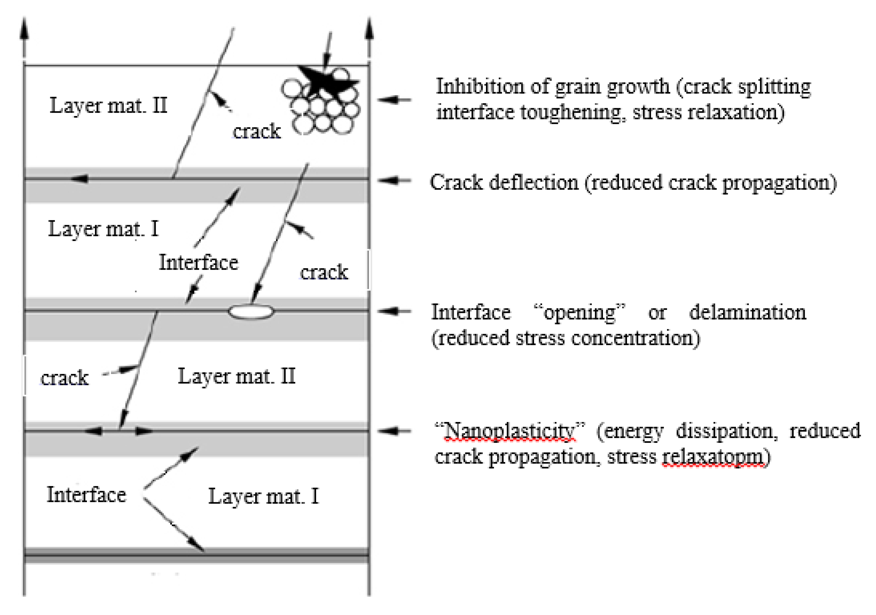
Multilayer coatings are widely used as an effective means to improve the fracture toughness of coatings, while maintaining hardness, wear resistance and other mechanical properties. In multilayer structures, the mechanisms of toughening include (see
Figure 10): Crack splitting at the boundaries of small sized grains; crack deflection at the interface between layers, reduction of stress concentration by interface opening; and plastic deformation at the interface for energy dissipation and stress relaxation, “nanoplasticity” [
29].
TiAlSiN/CrAlYN films synthesized on cemented carbide, silicon and SUS304 substrates with a period of 8.7 nm exhibited the highest hardness with 37.1 GPa, which was higher than the value of TiAlSiN monolayer and CrAlYN monolayer (
Figure 11) [
30].
Figure 10.
Mechanisms of toughness enhancement in hard ceramic multilayers [
29].
Figure 10.
Mechanisms of toughness enhancement in hard ceramic multilayers [
29].
Figure 11.
Vickers microhardness of the multilayer films as a function of the multilayer period [
30].
Figure 11.
Vickers microhardness of the multilayer films as a function of the multilayer period [
30].
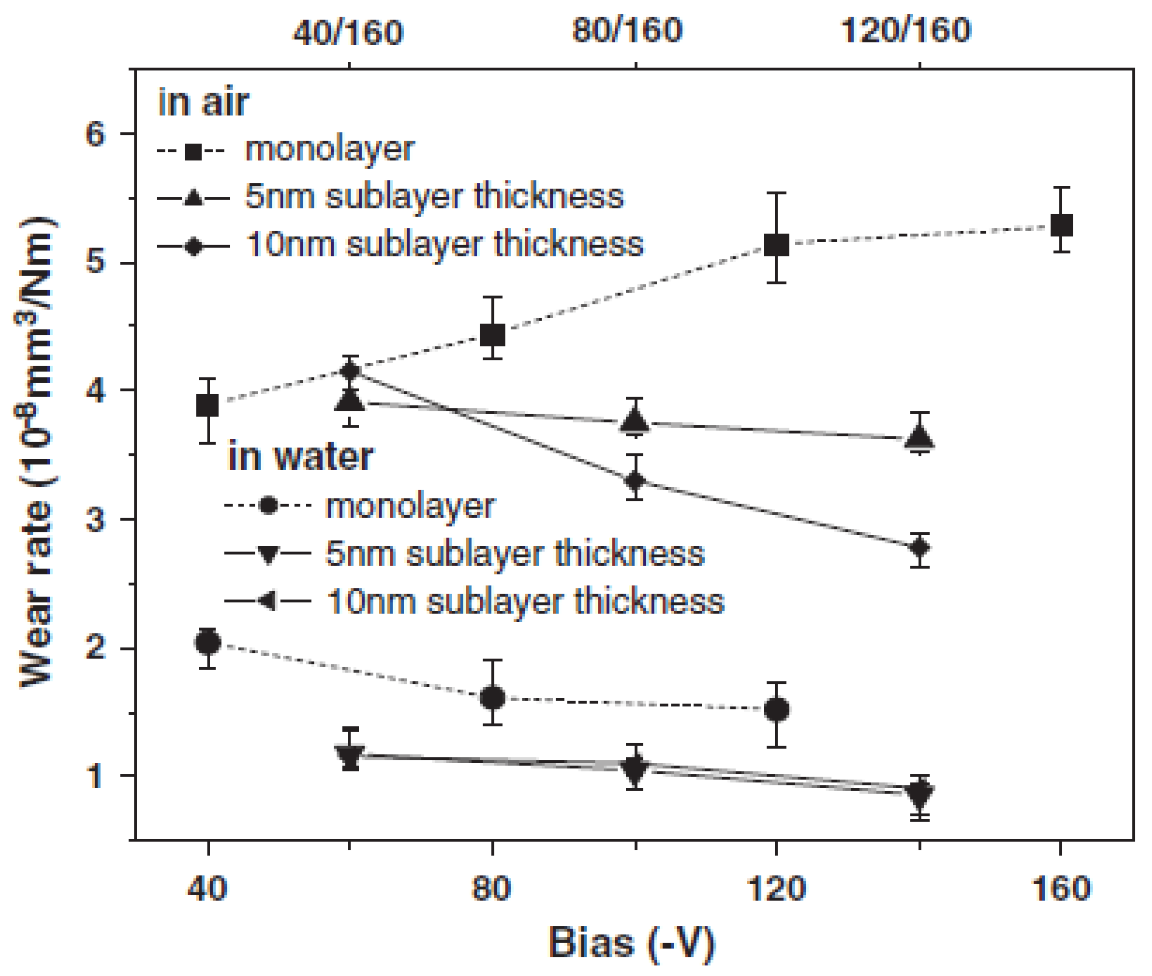
Zhang
et al. found the multilayer diamond-like carbon (DLC) films deposited at a bias alternating between −120 and −160 V almost doubled the toughness of monolayer DLC films and had better wear behaviors (
Figure 12). The multilayer structure with a low modulus ratio contributed to reduced stress concentration in harder sub-layer, thereby inhibiting crack initiation [
31].
Figure 12.
Wear rate of monolayer DLC films and multilayer DLC films as a function of substrate bias [
31].
Figure 12.
Wear rate of monolayer DLC films and multilayer DLC films as a function of substrate bias [
31].
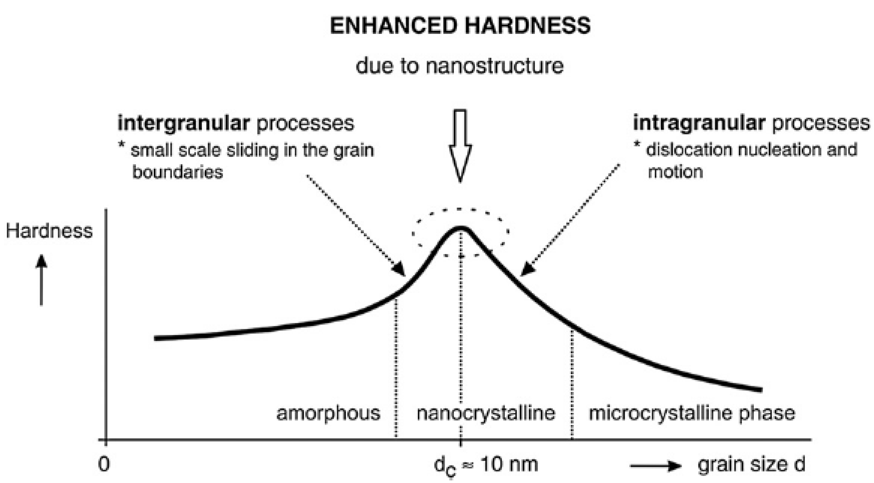
Nanocomposite coatings provide similar advantages as multilayers, while without limitations of thickness and substrate geometry. The main mechanisms responsible for increased hardness and toughness are [
28] (
Figure 13): Dislocation-induced plastic deformation; nanostructure of materials; and cohesive forces between atoms. The dislocation-induced plastic deformation dominates in the materials composed of large grains with sizes >10 nm. On the contrary, the nanostructure is dominant in materials composed of small grains with sizes ≤10 nm.
Figure 13.
Schematic illustration of coating hardness as a function of the size d of grains [
28].
Figure 13.
Schematic illustration of coating hardness as a function of the size d of grains [
28].
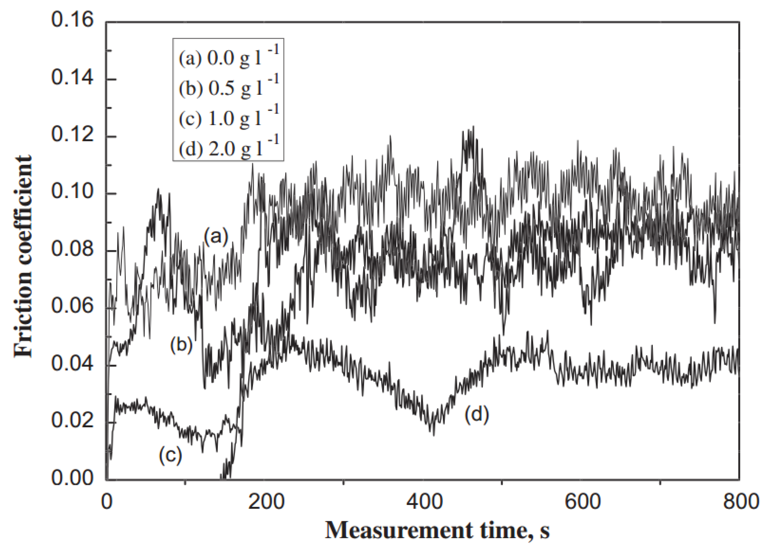
When grain sizes in such composites are reduced to a nanometer level, dislocation activity as a source of ductility is eliminated. However, these types of composites contain a high volume of grain boundaries with a crystalline/amorphous transition across grain-matrix interfaces, limiting initial crack sizes and helping to deflect and terminate growing cracks. These mechanisms may explain the brittle resistance of novel superhard composites [
32]. Li
et al. reported the incorporation of alumina nanoparticles can increase the micro-hardness and wear resistance of electroless Ni-P/Al
2O
3 nanocomposite coatings (
Figure 14) [
33].
Figure 14.
The friction coefficient of electroless Ni-P coatings (heat-treated at 300 °C for 90 min) at various particle concentrations under dry sliding conditions [
33].
Figure 14.
The friction coefficient of electroless Ni-P coatings (heat-treated at 300 °C for 90 min) at various particle concentrations under dry sliding conditions [
33].
Bakhit
et al. found the maximum microhardness of 651 HV was obtained for the Ni-Co/SiC nanocomposite coatings deposited at the optimum conditions corresponding to the maximum incorporation of the SiC nano-particles of 20 v%. The strengthening mechanism induced by the SiC nano-particles was found to be the hindering of the grain boundary mediated processes [
34].
Ali reported the average microhardness value of ceramic nanocomposite coatings fabricated from lithium sulphated zirconium silicate bath was approximately 8.5 times higher than that of the as-received aluminum [
35].
Combination of the nanocrystalline/amorphous designs with a functionally graded interface provides high cohesive toughness and high interface toughness in a single coating. The large fraction of grain boundary phase provides ductility through activating grain boundary slip and crack termination by nanocrack splitting. This provided a unique combination of high hardness and toughness in these coatings.
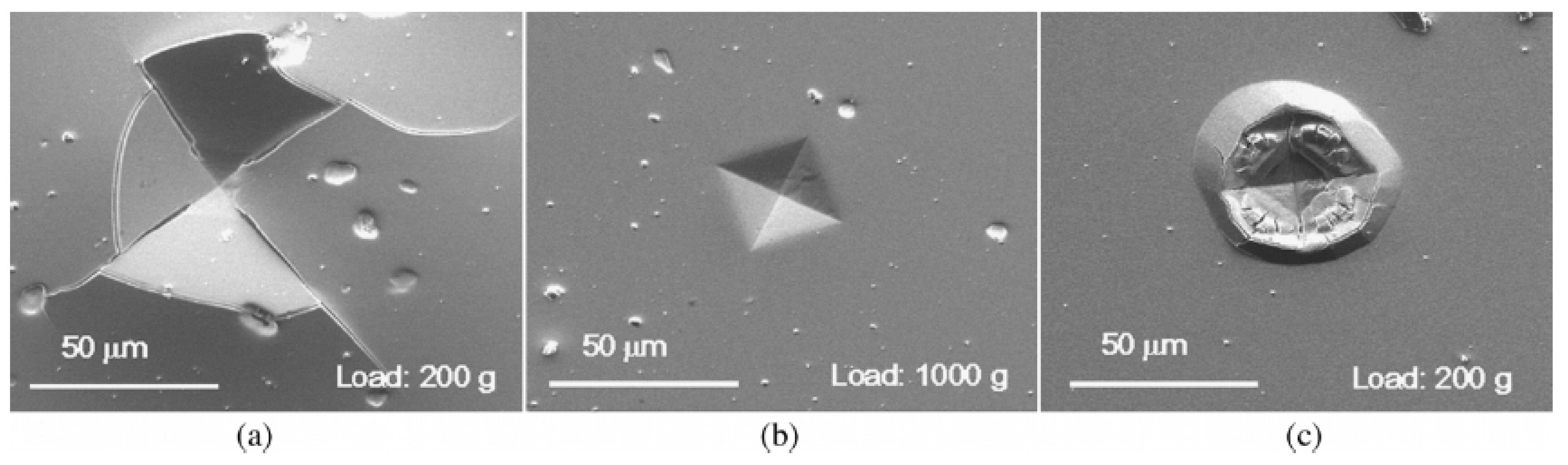
Figure 15 shows Vickers indentations of YSZ-Au coating. There were no observable cracks in these coatings, even after significant substrate compliance [
36].
Ranand
et al. studied Ti-TiB
2 nanocomposite coatings using dual-cathode magnetron sputtering in Ar onto polished titanium and silicon substrates. Ti-TiB
2 nanocomposite coatings exhibited a flatter hardness-toughness relationship compared with metal carbide-DLC and TiN-Si
3N
4 nanocomposite coatings, since the formation of coherent Ti-TiB
2 interfaces, which produced stress fields activating the motion of nearby dislocations within the Ti matrix and hence improved fracture toughness [
37].
Figure 15.
Vickers indentation sites on the surface of YSZ-Au films with varying gold content: (
a) 5; (
b) 12; and (
c) 35 at % Au [
36].
Figure 15.
Vickers indentation sites on the surface of YSZ-Au films with varying gold content: (
a) 5; (
b) 12; and (
c) 35 at % Au [
36].
Movahedi reported the NiAl-15 wt% (Al
2O
3-13% TiO
2) nanocomposite coating was tougher and harder than the NiAl intermetallic coating. The wear behavior is attributed to the high fracture toughness of the nanocomposite coating rather than to the brittle NiAl intermetallic coating. The average specific wear rate for NiAl-15 wt% (Al
2O
3-13% TiO
2) nanocomposite coating was measured to be 0.78 ± 0.33 × 10⁻¹⁵ m
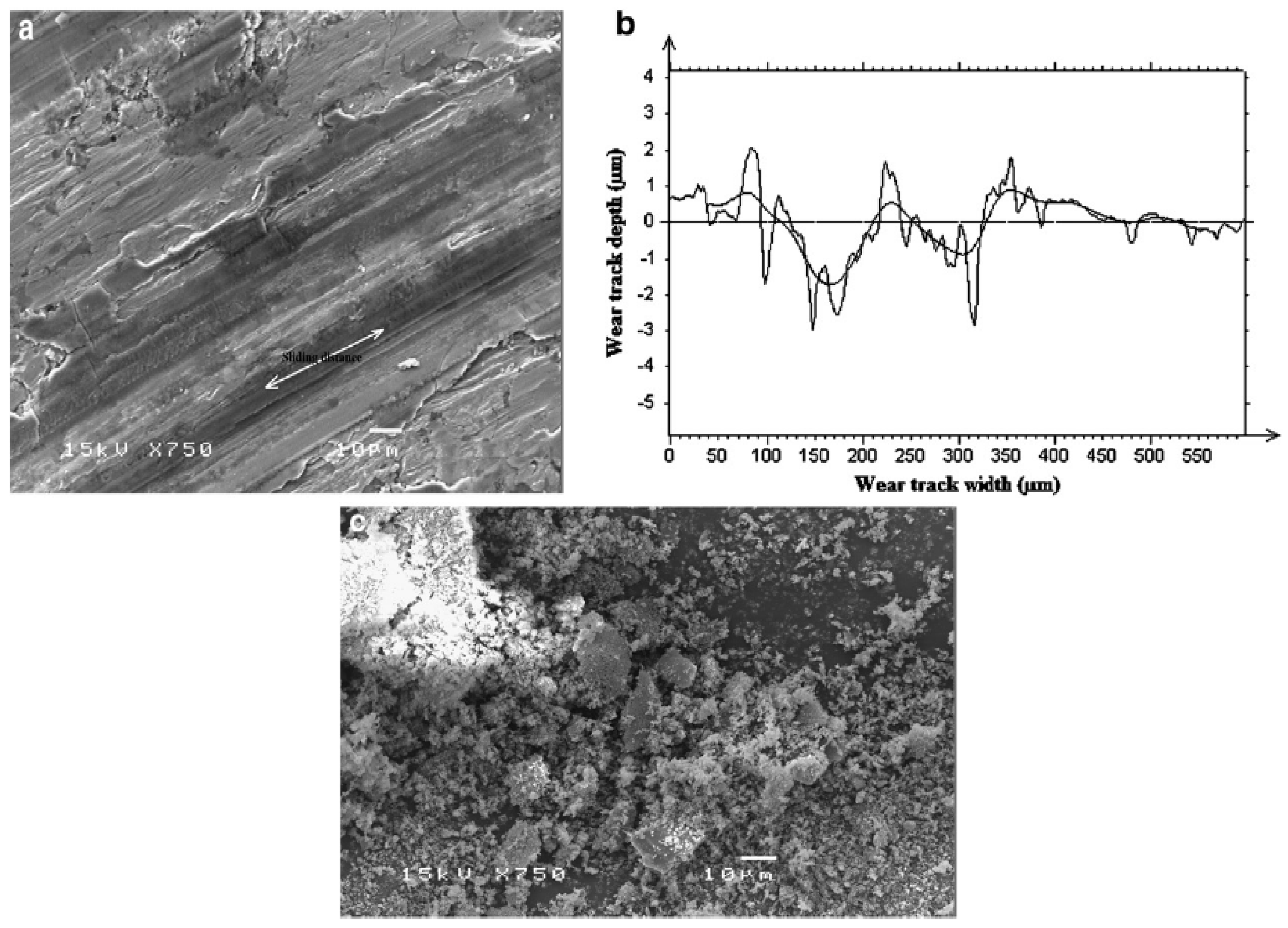
3/N·m, much less than that for NiAl intermetallic coating. SEM micrographs of the wear track are shown in
Figure 16. The changes in the wear resistance between NiAl intermetallic and NiAl-15 wt% (Al
2O
3-13% TiO
2) nanocomposite coatings were attributed to the changes in the susceptibility to crack propagation by adding Al
2O
3-13% TiO
2 nanoparticles as the reinforcing materials [
38].
Figure 16.
(
a) SEM micrographs of the wear track; (
b) Surface profile of worn surface; and (
c) Wear debris of the NiAl-15 wt% (Al
2O
3-13% TiO
2) nanocomposite HVOF coating [
38].
Figure 16.
(
a) SEM micrographs of the wear track; (
b) Surface profile of worn surface; and (
c) Wear debris of the NiAl-15 wt% (Al
2O
3-13% TiO
2) nanocomposite HVOF coating [
38].
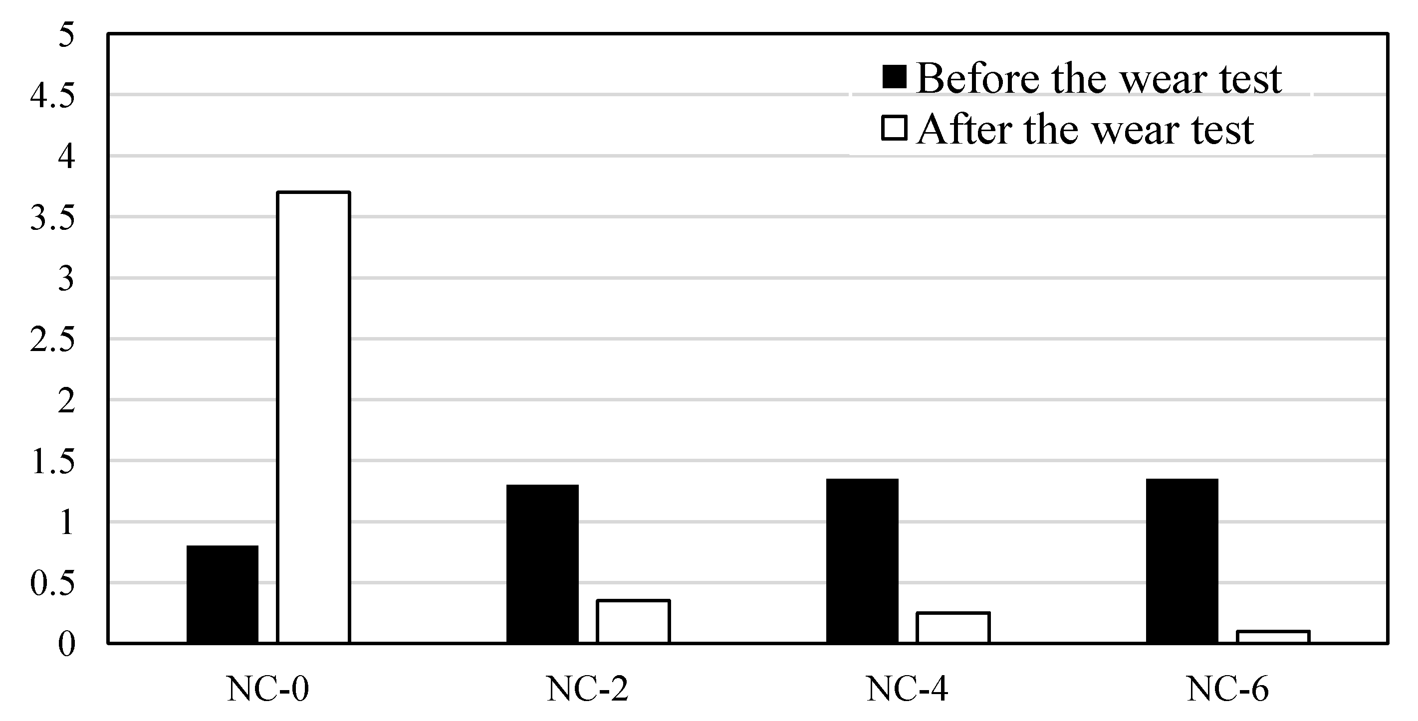
To reduce the friction coefficients and improve the anti-abrasive properties, Ni-based alloy coatings reinforced by TiC particles, graphite/TiC/Ti based alloys (GTN) were prepared on the surface of carbon steel [
39]. The addition of graphite to the GTN coatings can greatly reduce the friction coefficients and enhance the wear resistance. Under a low load, the wear mechanisms of the GTN coating were mainly multi-plastic deformation with slightly abrasive wear and gradually changed into a mixture of multi-plastic deformation, delamination, and micro-cutting wear with the increase of graphite fraction. As the load increased, the main wear mechanism gradually changed from micro-cracks, micro-cutting, and adhesive wear to micro-cutting and micro-fracture with the increase of graphite fraction [
39].
Nickel composites with various ceramic particles, such as Al
2O
3, SiC, B
4C, SiO
2, WC, and TiC, prepared by the composite plating method using an ethanol based nickel bath can produce better anti-abrasive coatings. Particles can be easily co-deposited with nickel in the ethanol bath. But most hydrophilic particles like SiO
2 can be hardly co-deposited from a non-aqueous metal plating bath. From wear experiments of these coatings, it can be concluded that the anti-abrasive property of a nickel-ceramic coating from the ethanol bath is much better than that of the same nickel-ceramic from the water plating bath [
40].
Electroless nickel (EN) plating is an auto-catalytic reaction used to deposit a coating of nickel on a substrate. Unlike electroplating, it is not necessary to pass an electric current through the solution to form a deposit. This plating technique is to prevent corrosion and wear. EN techniques can also be used to manufacture composite coatings by suspending powder in the bath [
41]. Electroless nickel plating has several advantages
versus electroplating. Free from flux-density and power supply issues, it provides an even deposit regardless of workpiece geometry, and with the proper pre-plate catalyst, can deposit on non-conductive surfaces [
42].
Vitry
et al. [
43] investigated the mechanical and wear properties of electroless nickel-boron coatings. The hardness of the deposits increased from 900 to 1250 HV
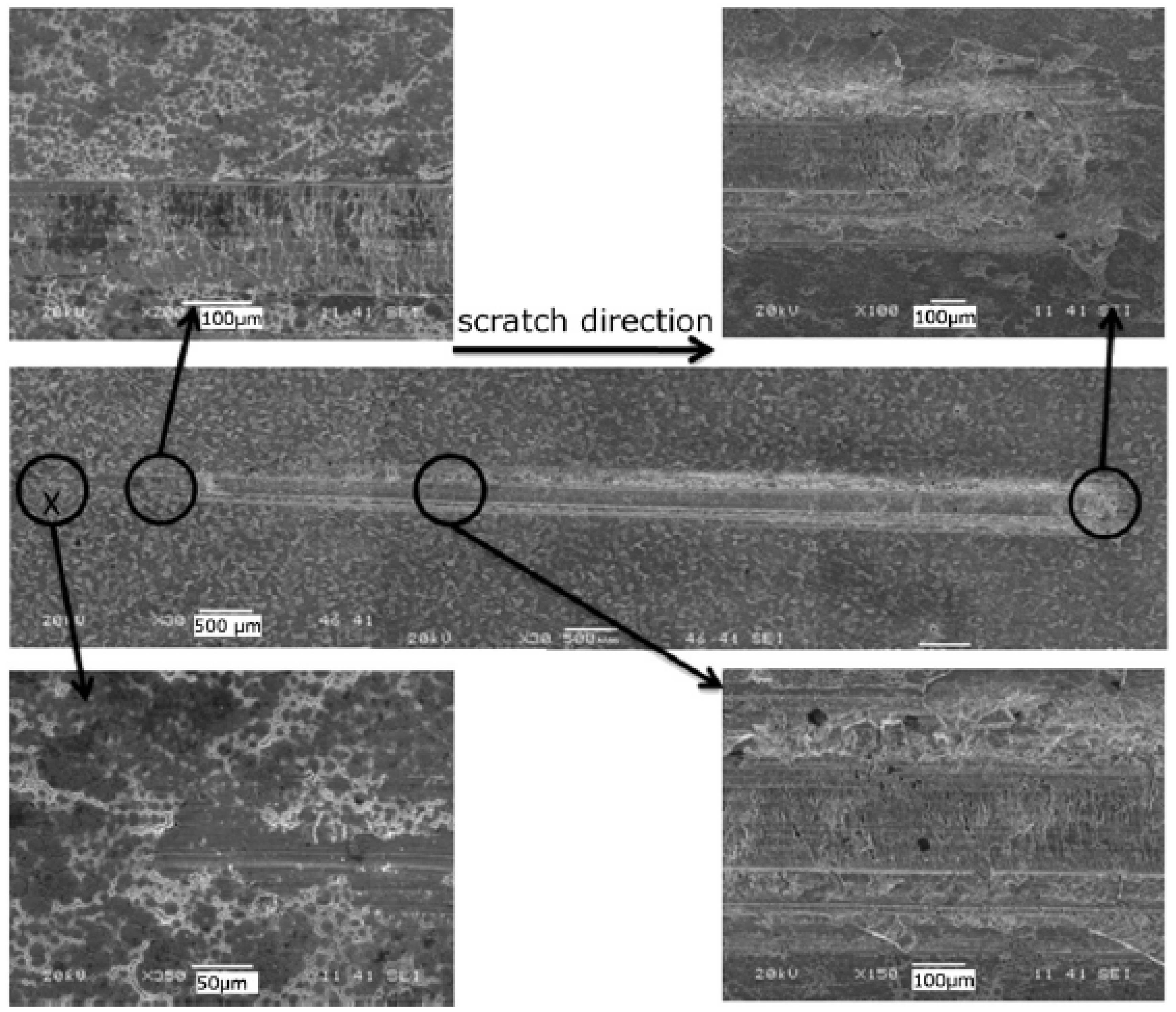
2.5 due to optimal crystallization of the nanocrystalline coating after heat treatment at 400 °C for 1 h. This increase of hardness is due to both the Hall-Petch effect and to phase transformation that occurs during heat treatment from supersaturated nickel to nickel boride. The heat treated coatings showed a good response to the wear test, without spalling nor delamination (
Figure 17), with an overall metallic ductile behavior throughout the tests [
43].
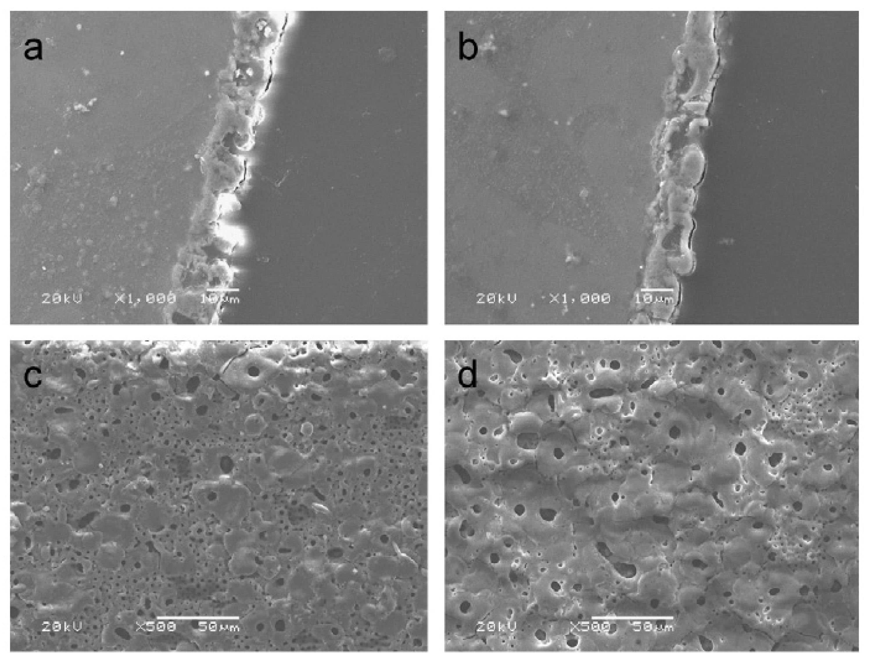
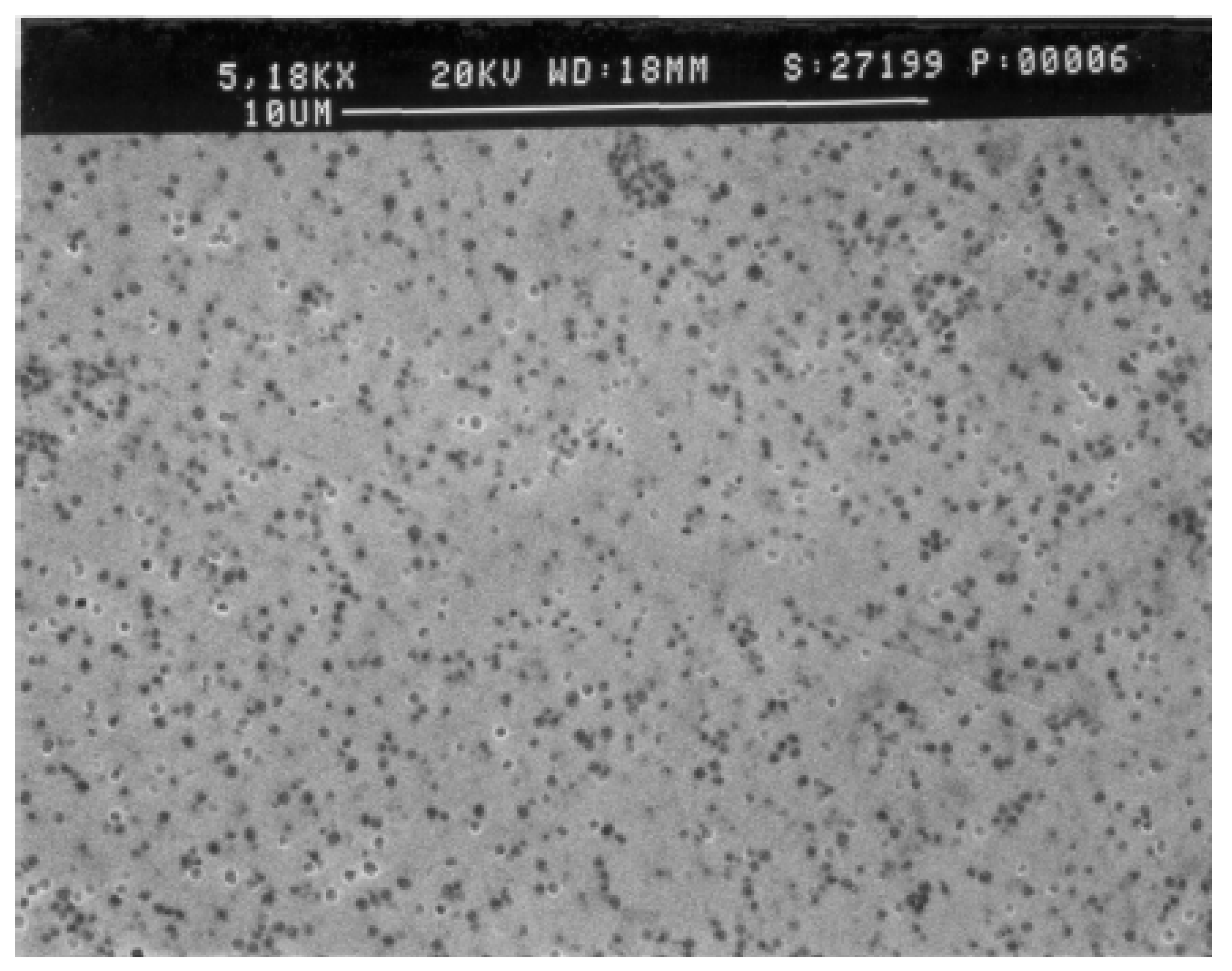
The tribological performance of electroless nickel or bronze can be further improved with the introduction of polytetrafluoroethylene (PTFE) particles (
Figure 18 and
Figure 19) [
44]. The coating covered workpiece surfaces very well without any defects even at the corners, which enhanced the break-in period for highly polished, critical surfaces of the molding cavity or core.
Figure 17.
Observation of the scratch tracks up to 150 N on a 25 μm thick electroless nickel-boron coating after heat treatment at 400 °C for 1 h [
43].
Figure 17.
Observation of the scratch tracks up to 150 N on a 25 μm thick electroless nickel-boron coating after heat treatment at 400 °C for 1 h [
43].
Figure 18.
Scanning electron micrograph of the surface of nickel with PTFE protected sample [
44].
Figure 18.
Scanning electron micrograph of the surface of nickel with PTFE protected sample [
44].
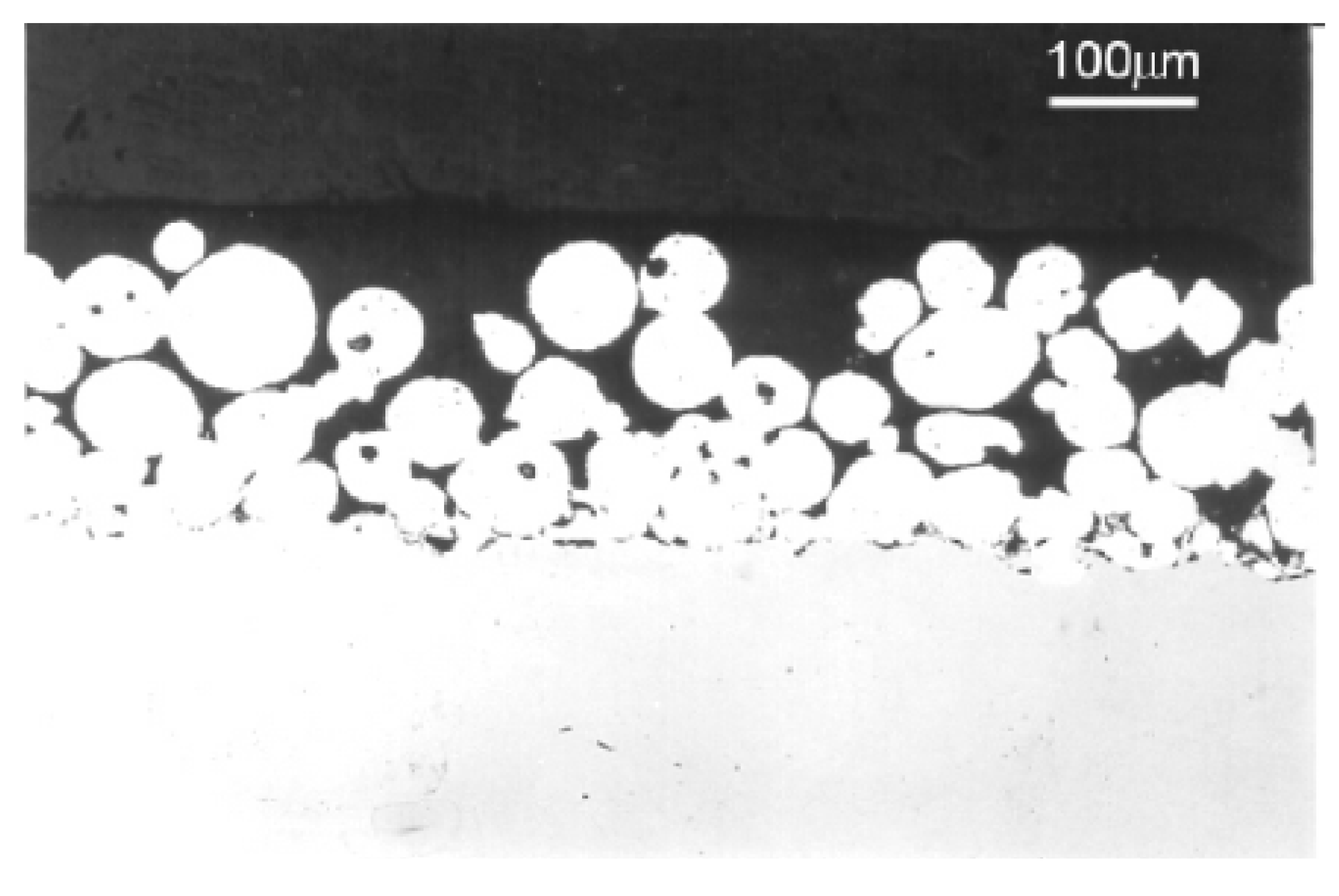
Figure 19.
Optical micrograph of the cross section of the sample protected with bronze particles in a PTFE matrix [
44].
Figure 19.
Optical micrograph of the cross section of the sample protected with bronze particles in a PTFE matrix [
44].
5. Ceramic Anti-Abrasive Coating
Ceramic coating can be used on the surface of metal or ceramic materials. Since ceramic has relatively high hardness, corrosion resistance and heat resistance, it can be widely used as a protection coating. Typical ceramic coatings include Al2O3/TiO2, SiO2/TiO2/Cr2O3, SiC, B4C, ZrO2, CaO, CrN/AlCrN, CrN/BCN, SiO2, WC, and TiC.
It was found that the property and microstructure of the coatings are affected by the critical spray process parameters (CPSP). The specific parameter of the spray condition is determined by optimization of the coating spray process and the anti-abrasive performance. The coating powder can be reconstructed into plasma sprayable size agglomerates by controlling CPSP and adding additives. The reconstruction process of plasma sprayed coating included an additional step of plasma processing, during which the reconstructed spraying powders were pre-heated and air-quenched in a collection chamber.
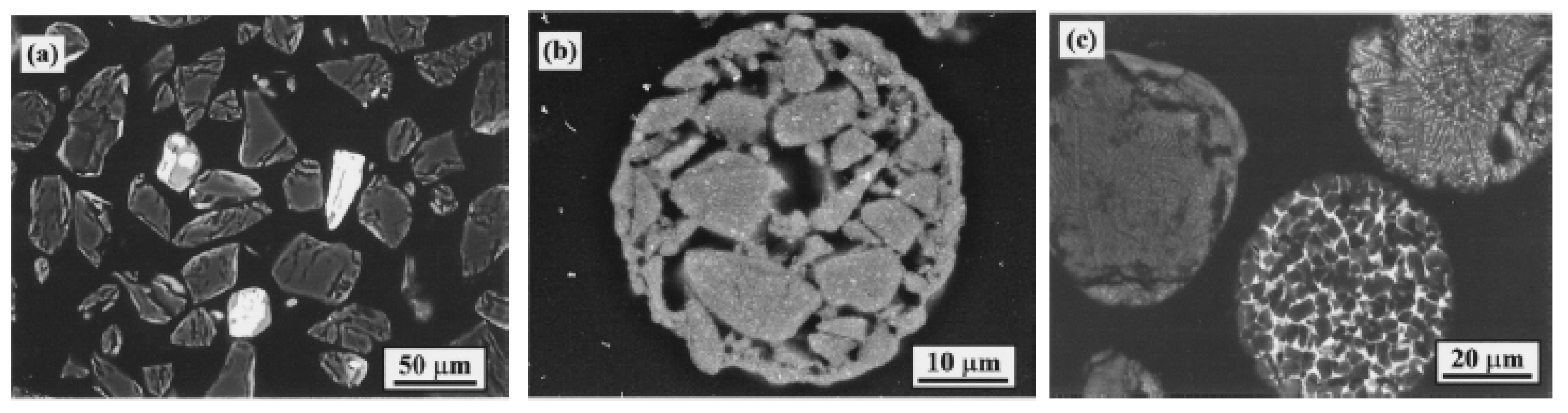
Figure 20 shows the cross-section view of different sprayed powders. Nanostructured Al
2O
3 and 13 wt% TiO
2 coating powders were mixed and reconstituted to a size that is suitable to spray. The α-Al
2O
3 were shown in black. The TiO
2 grains were dissolved in oxide additives for the modified powders, and are shown in bright regions [
45].
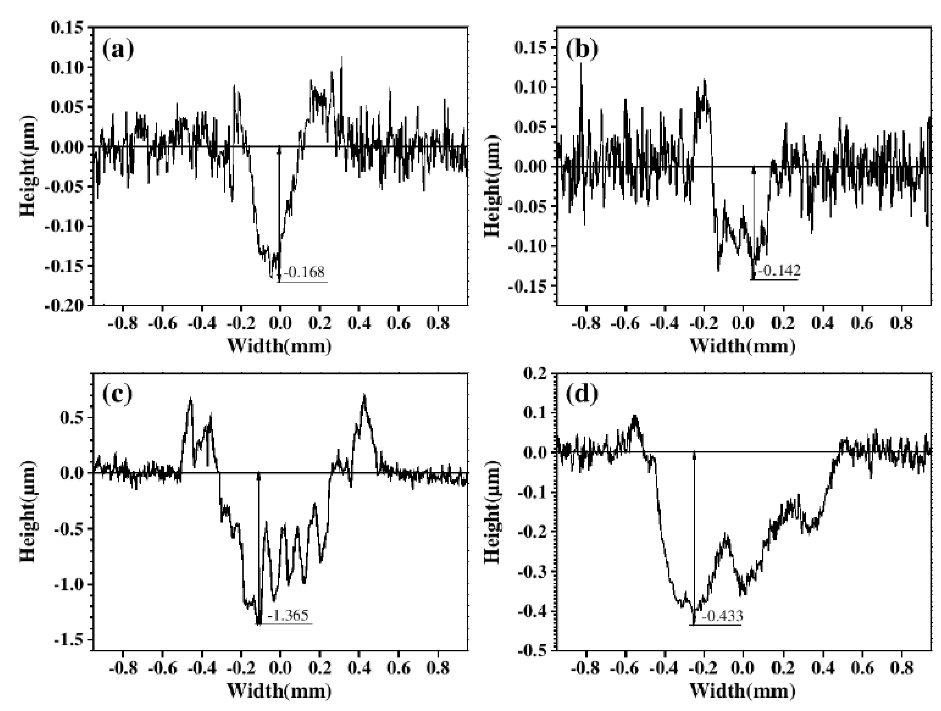
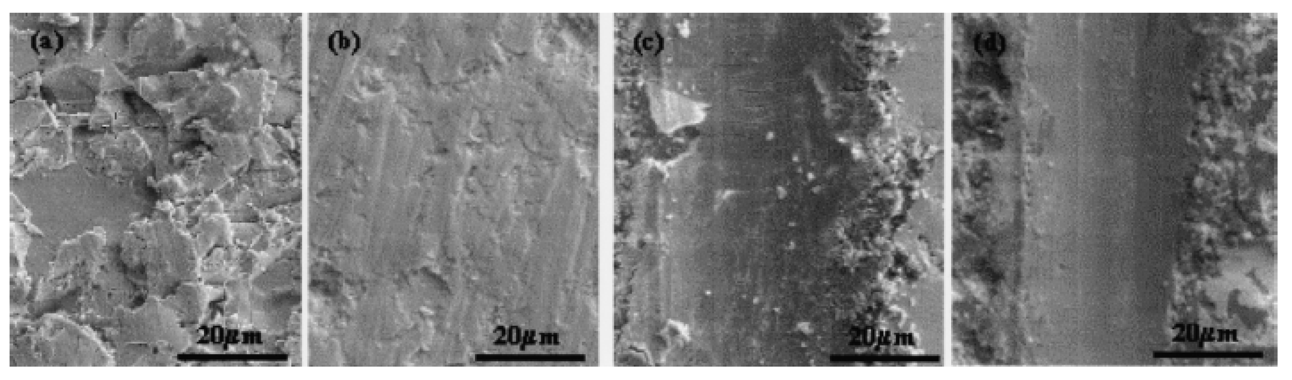
From
Figure 21, it can be found that the reconstituted coating has a significant improvement in the anti-abrasive performance. Through a broad range of mechanical properties testing of the nanostructured alumina-titanium oxidize coating, it was found that the nanostructured coating exhibited a superior anti-abrasive performance [
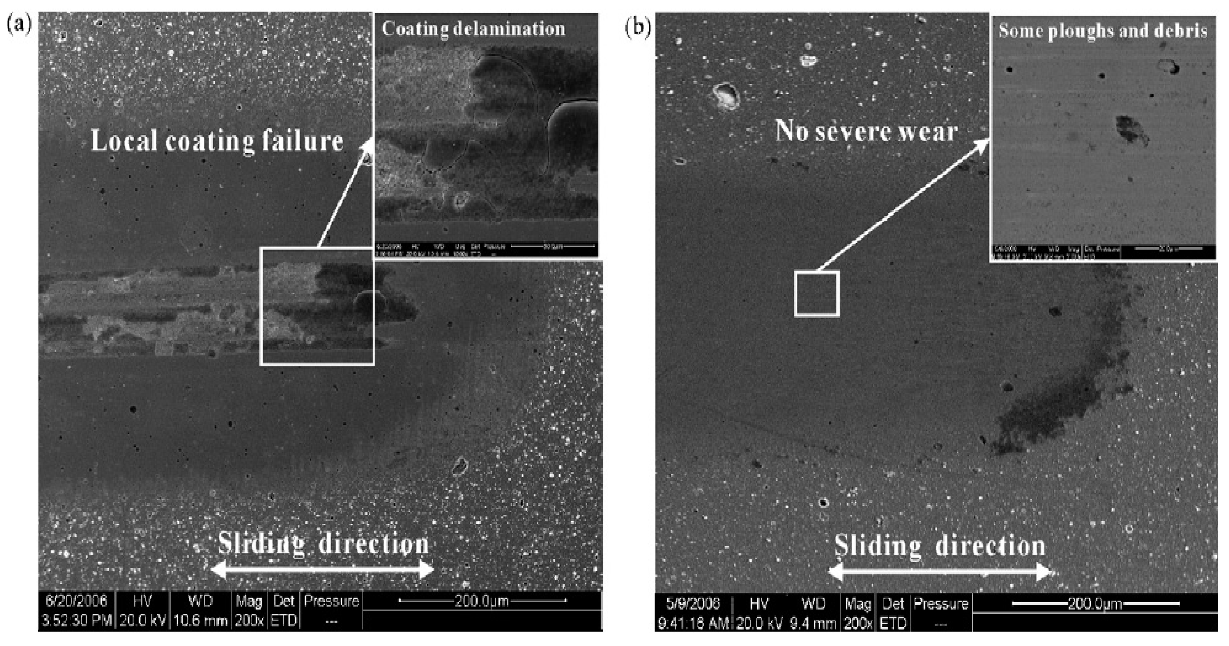
45]. AlCrN (high aluminum-content) coating can be deposited by the multi-arc plating technique. Since the physical vapor deposited (PVD) CrN coating has a relatively good oxidation, anti-corrosive, and anti-adhesive properties, it can be widely used in industrial applications. It has been found that CrN and aluminum alloy composite shows a significant increase in hardness and has remarkable anti-abrasive performance. From the reciprocating sliding tribological behavior testing of the AlCrN coating against Si
3N
4 ceramic and pure titanium balls, it can be illustrated that the AlCrN coating showed a significant improvement in wear debris removal efficiency and load-carrying capacity as compared to the CrN coating. The CrN coating suffered severe concentrated wear under high normal load conditions [
22].
Figure 20.
Backscattered electron micrographs of (
a) Metco-130 powders and reconstituted (
b) Al
2O
3-13 wt% TiO
2 without the additives and (
c) Al
2O
3-13 wt% TiO
2 with the additives [
45].
Figure 20.
Backscattered electron micrographs of (
a) Metco-130 powders and reconstituted (
b) Al
2O
3-13 wt% TiO
2 without the additives and (
c) Al
2O
3-13 wt% TiO
2 with the additives [
45].
Figure 21.
Surface morphology of sprayed coating (
a,
c) Metco-130 (
b,
d) reconstituted nanostructured Al
2O
3-13 wt% TiO
2 coatings after the (
a,
b) abrasive wear and (
c,
d) scratch test [
45].
Figure 21.
Surface morphology of sprayed coating (
a,
c) Metco-130 (
b,
d) reconstituted nanostructured Al
2O
3-13 wt% TiO
2 coatings after the (
a,
b) abrasive wear and (
c,
d) scratch test [
45].
6. Polymer Coatings
Polymer can be used as typical anti-friction coating by fluidization on the metallic matrix [
1]. Polymers such as PA (polyamide) or PE (polyethylene) can be directly deposited on the surface of metal materials by fluidization, where a fluid (liquid or gas) is passed up through the granular material and convert granular material from a static solid-like state to a dynamic fluid-like state. The optimal thickness of the polymer coating is about 0.3 mm. The polymer coating can reduce the friction coefficient. The utility of the thin polymeric coating instead of a thick polymeric solid element can transport heat from the wearing area faster than the thick polymer coating. When a PA coating rubs against steel, the friction coefficient was lower (below 0.15) than the thick PA elements [
1].
Polymer can also be used as additives to the alloy coating and ceramic coating. When the polymer is used as the addictive, the polymer can bond the alloy grain or ceramic granular by its long molecular chains. That can link the granular extremely compact so that the composite can form a dense coating layer, thus, resisting wear. Zhu and Wang have prepared an oxide coating with additive of ethylene glycol gligmers on the AZ31B Mg alloy in an environment friendly electrolyte with additives by plasma electrolytic anodization [
46]. The performance of the anodized film was investigated. The films were found mainly consisting of MgO, MgSiO
3, Mg
2SiO
4. The surface morphologies were more and more compact and homogenous with the increase of the PEG (polyethylene glycol). The improvement in abrasive resistance of the anodic film formed in the electrolyte may be attributed to its much more compact surface and the incorporation of ductile PEG chains among those oxides [
46].
Brzezinski
et al. produced a thin-coat on the textile using sol-gel method. The coating can gain a great abrasive resistance performance [
47]. SiO
2 and Al
2O
3 were used as the sol, and glycidoxy-propyltrimethoxy silane aluminum isopropoxide was used as precursors on the fiber/fabric surface. Comparing with the texture without any coating, the abrasion resistance of the coating has been increased by about five times [
47].
7. Diamond-Like Carbon Coatings
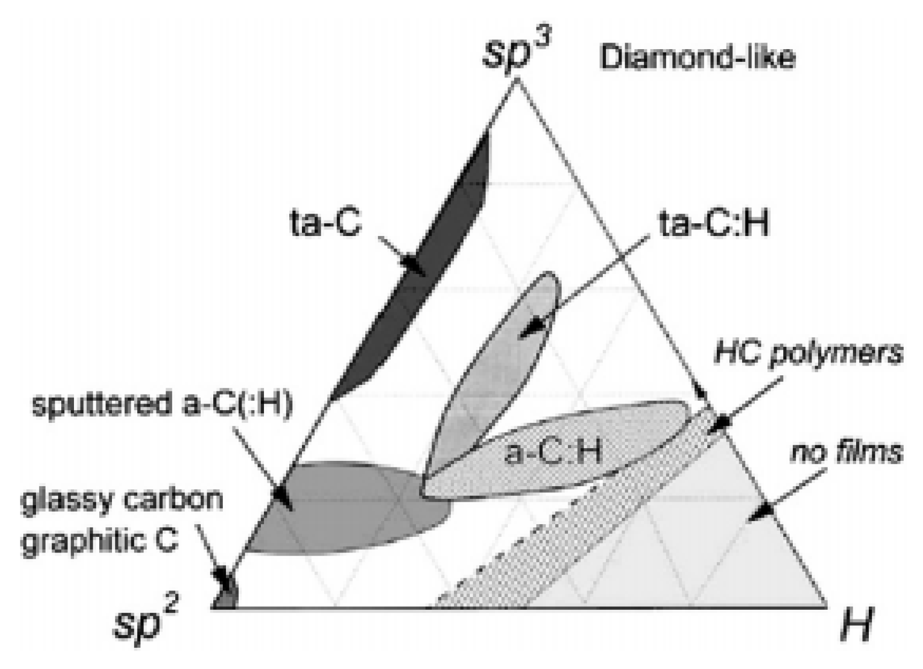
Diamond-like carbon (DLC) exists in amorphous carbon materials that show some typical properties of diamond. Depending on the ratio of sp
2 and sp
3 bonds and hydrogen content, DLC are divided into several groups, as shown in
Figure 22. The amorphous carbon (a-C) coatings with mainly sp
2 bonds are in the lower left corner of diagram. The hydrogenated amorphous carbon (a-C:H) has some hydrogen content and relatively low sp
3 bonds. Hydrocarbon polymers are located in the right corner. The sputtered hydrogenated amorphous carbon (a-C:H) has both sp
2 bonds and sp
3 bonds, and it is in the middle of the diagram. Coatings using plasma enhanced vapor deposition with more sp
3 bonds the hydrogenated tetrahedral amorphous carbon (ta-C:H). The tetrahedral amorphous carbon (ta-C) has a majority of sp
3 bonds and barely no hydrogen content [
48].
Figure 22.
Ternary phase diagram of sp
2, sp
3, and hydrogen contents of various forms of DLC [
48].
Figure 22.
Ternary phase diagram of sp
2, sp
3, and hydrogen contents of various forms of DLC [
48].
DLC coatings exhibit a combination of a low coefficient of friction and high micro-hardness, making them extremely effective in many tribological and wear applications. He
et al. applied DLC coatings to the surface of steel bearings to reduce the negative effect of contaminants in lubricant [
49]. The study showed that DLC coatings produced a very low friction and a high sliding wear resistance to improve the tribological properties and durability of running components. However, the protective coatings caused even more damage to the running components once they have been broken up by hard contaminants [
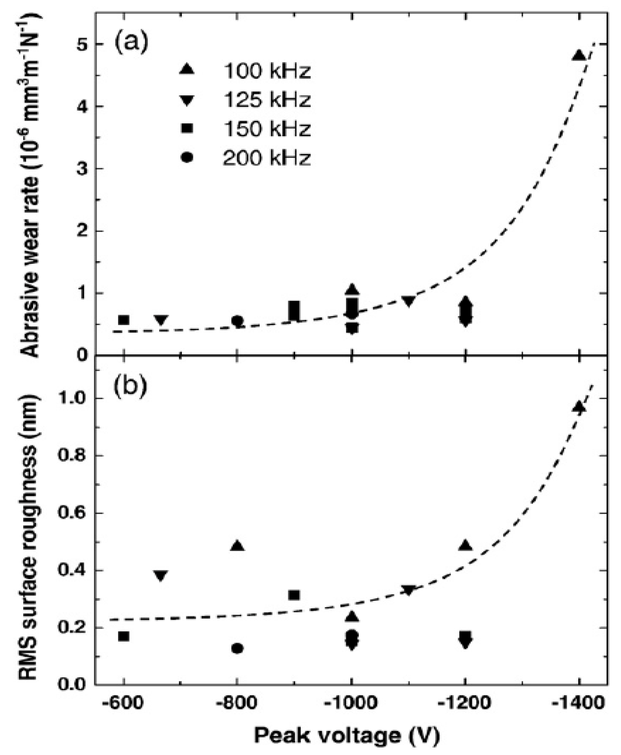
49]. Corbella and Rubio-Roy prepared DLC films by plasma-enhanced chemical vapor deposition [
25]. They measured the abrasive wear rate and the coefficient of friction of the DLC films deposited at different pulse frequencies and peak voltages. The surface roughness of DLC was much higher with an increase of one order of magnitude at high peak voltage at 100 kHz, while the coefficient of friction was lowered by increasing the peak voltage [
25].
Yuan and Brown’s research studied the atomic structures of DLC by using electron energy loss spectroscopy (EELS) [
50]. The study showed that the DLC films by using ion beam deposition consisted mostly of sp
3-bond atoms which play critical role in its mechanical rigidity and chemical inertness, but also high friction. The small amount of sp
2 carbon clusters were responsible for optical absorption gap and electric conduction [
50]. The sp
2 bonding provides low friction, but also low hardness. There is, thus, a balance between achieving both high hardness and low friction.
The application problem of hydrogenated carbon coatings is their very low fracture toughness. One method to resolve this problem is to incorporate ceramic materials into a-C:H coatings. This design allows users to have moderate hardness, stiffness, good fracture resistance, and retain their good tribological properties. Cr
2C nanoparticles can be considered as energy barriers that increase fracture toughness from K
IC (changes of fracture toughness) = 1.55 MPa·m
0.5 for the a-C:H coating up to K
IC = 1.7–3.4 MPa·m
0.5 for nanocomposite coatings. And the lowest wear index found for Cr
2C/a-C:H coatings was about seven times smaller than for a-C:H coatings [
51].
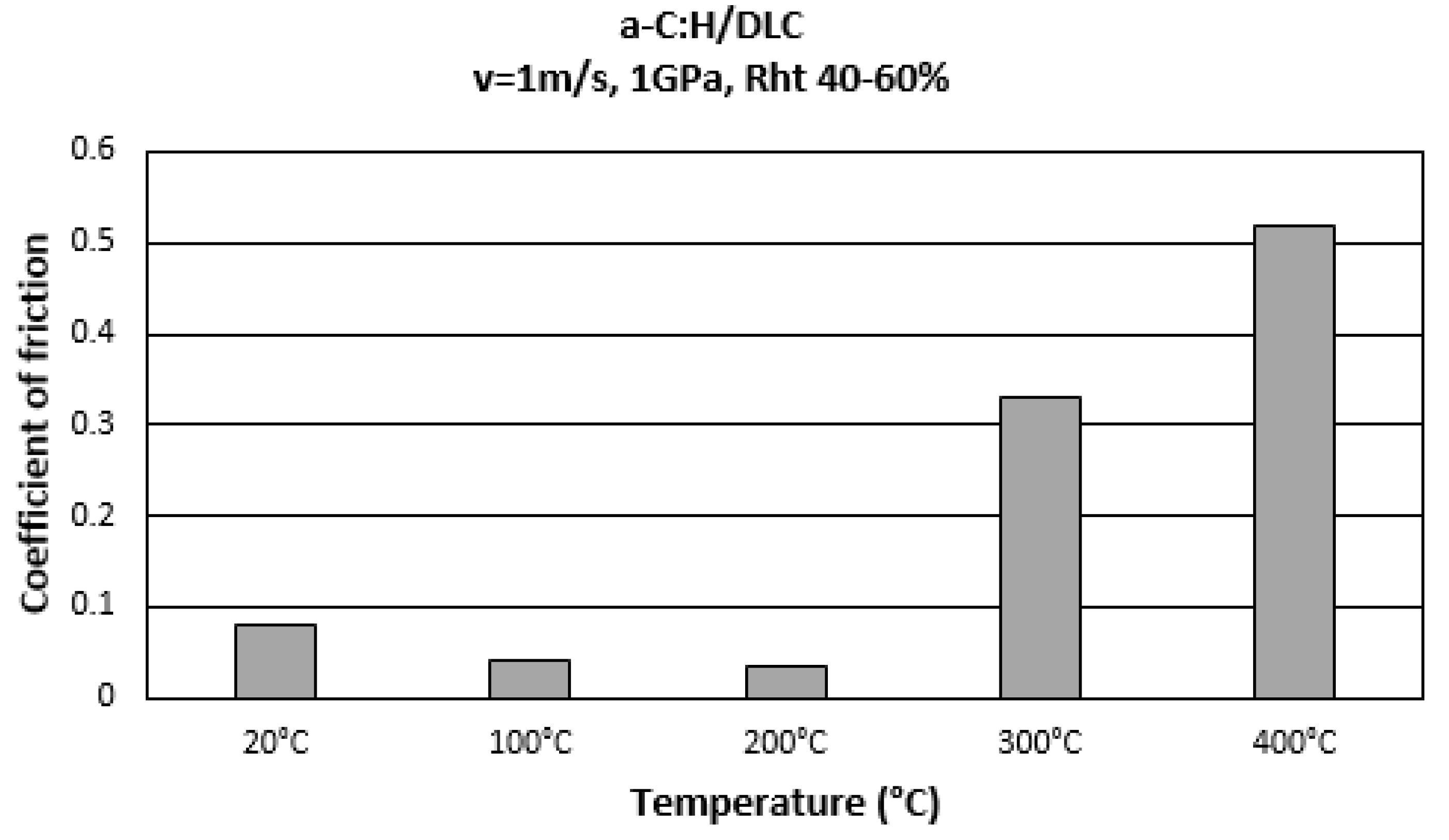
Working conditions or contact parameters are one important factor in DLC coating performance. Bremond
et al. [
52] found friction increase tremendously at high temperature due to the ruin of DLC coatings (see
Figure 23). High friction is related with the presence of titanium and metallic particles in the contact [
52].
Figure 23.
Influence of working temperature on coefficient of friction of a-C:H coating [
52].
Figure 23.
Influence of working temperature on coefficient of friction of a-C:H coating [
52].
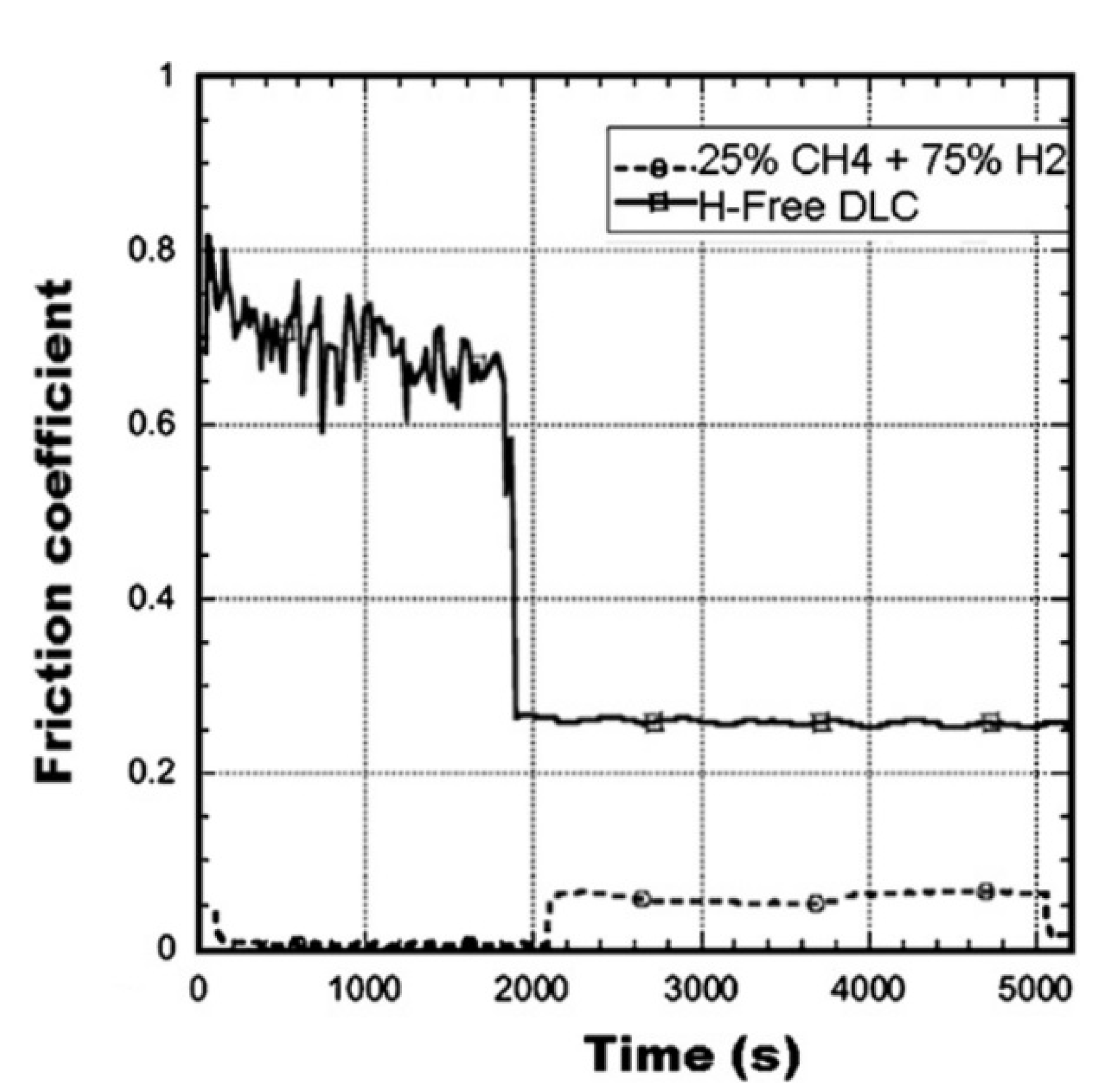
The hydrogen content in DLC coatings can significantly affect the tribology properties of these coatings. DLC coatings with hydrogen content have low coefficient of friction about 0.05 in dry air. The elimination of strong covalent bond and better shielding of carbon atoms by dehydration lead to this phenomenon [
53]. It is well known that chemically active gas can have strong effect on the frictional properties of DLC coatings. Erdemir [
53] found DLC coating performance is humidity dependent. As long as the test environment is inert and dry, the friction coefficients of hydrogen-free are general be high, whereas those of the hydrogen-rich films would be low. As shown in
Figure 24, after humidity added, the friction coefficient dropped to 0.25, whereas the friction coefficient of hydrogenated films increased to 0.06 [
53].
The doping of DLC coating with different metals can change mechanical properties and tribological properties of coatings. Wei
et al. investigated the mechanical properties of diamond-like carbon (DLC) thin films that contain foreign atoms, prepared by pulsed laser deposition [
54]. Wear tests show improved wear resistance in the copper doped DLC coatings. Nanoindentation results give an average hardness above 40 GPa and effective Young’s modulus above 200 GPa for pure DLC. The copper doped DLC films showed slightly decreased hardness and Young’s modulus as compared to pure DLC films. Ti-DLC films with low concentration Ti doping exhibit low wear rate of 2.0 ± 0.2 × 10
−8 mm
3/Nm and a low friction coefficient of about 0.04 [
55].
Figure 24.
Effect of humidity on friction coefficient of hydrogen-free and hydrogenated DLC films [
52].
Figure 24.
Effect of humidity on friction coefficient of hydrogen-free and hydrogenated DLC films [
52].


