1. Introduction
The purpose of piston rings (PR) is to provide a sealing between the gap of the piston and the cylinder wall, whilst distributing and controlling the oil and transferring the heat along with stabilizing the piston. This is a departure from earlier days, where the sole purpose of the PR was just to seal off the combustion chamber. The PR in the internal combustion engine (ICE) is accountable for a significant amount of friction loss and the optimization of this tribosystem is very important to increase the overall fuel economy of the engine [
1]. For example, frictional losses of the piston-cylinder-contact (PCC, where the PR is in contact with the cylinder liner) in heavy duty diesel engines of trucks can contribute to the overall 4–15% of fuel consumption. As a result, billions of liters of fuel are lost to just overcoming the friction in these vehicles [
2]. Significant studies have been conducted in this area, such as R. Rahmani et al. explaining that the internal combustion engine will continue as the main ‘source of vehicular propulsion for the foreseeable future.’ The authors present a study that takes an integrated approach to the frictional losses, as well as discuss the emission losses of the piston-cylinder system. The conclusions of this experiment state that the cylinder liner temperature is critical in mitigating power loss, in addition to reducing Hydrocarbon and Nitrogen oxide emissions from the compression ring [
3]. It is important to note that the compression ring is located nearest to the piston head, which is the top of the piston [
4].
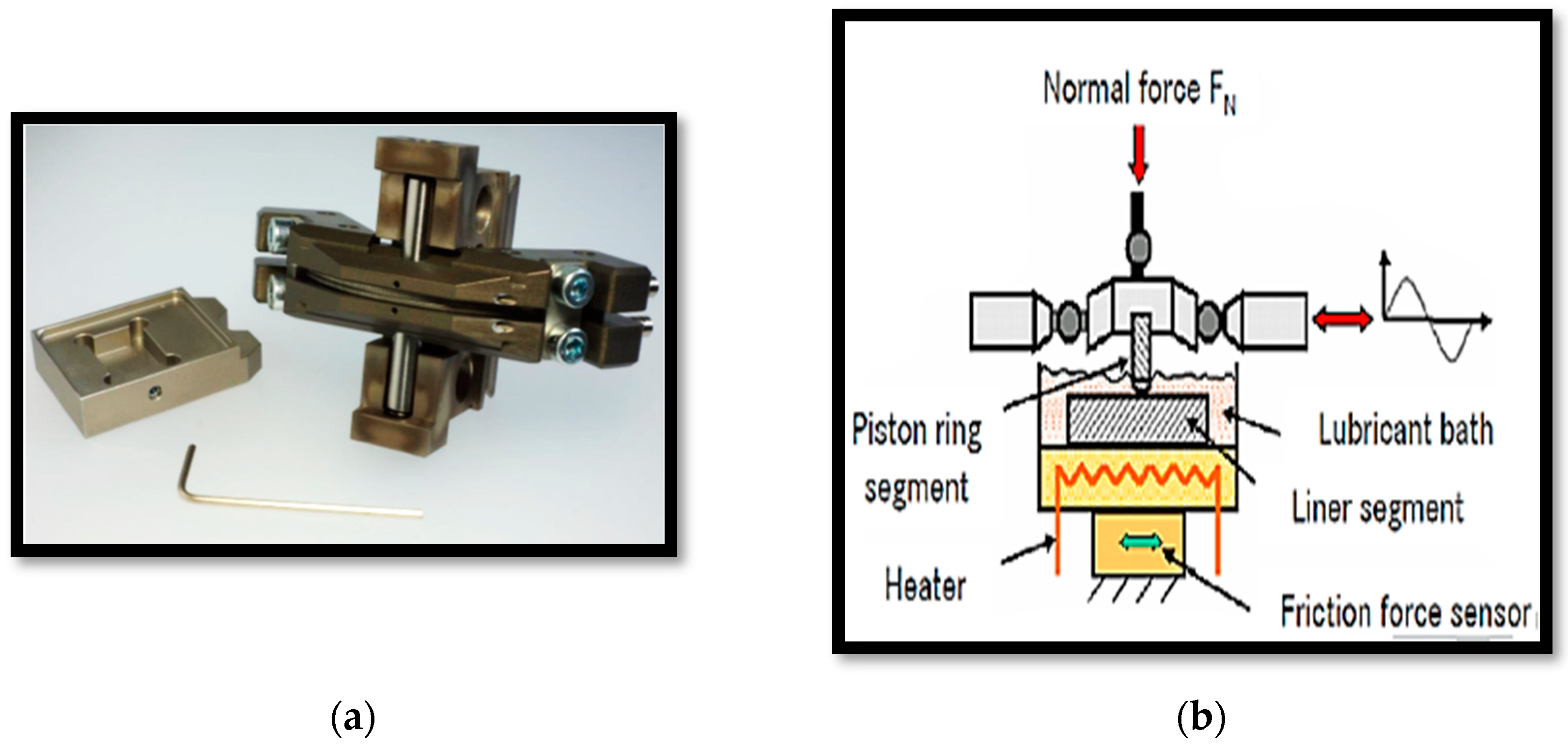
This paper offers a novel way to investigate the wear and friction generated by the PR oscillating against the cylinder liner using the SRV tester. This is otherwise known as SRV, which translated from German means oscillation, friction and wear. The SRV instrument can be used to closely simulate specific operating conditions relevant for the functioning of the PR in the ICE.
The primary investigation of this paper is: How different piston ring coatings influence the wear and the friction generated from the sliding motion of the PCC. To the authors’ knowledge, there are studies that do consider PR coatings and the effect of it on the PCC assembly but it is the novelty of how this investigation was conducted that presents a realistic, cost-efficient way of studying the PCC movement. Ultimately, it is the goal of such screening to suggest possible coatings of the PR in the PCC assembly, so that the PR can be possibly further optimized. By choosing this parameter of study, it offers a viable way the PR can be advanced without a need for a large change in the current settings of the PCC assembly in the engine, making it a feasible option to be considered for more studies. This approach is also suited for development of alternative and low viscosity engine oils.
2. Modeling the Friction of the Piston-Cylinder-Contact during Engine Operation
During operation cycle of 720° in the ICE, the PR passes all lubrication modes on the cylinder liner and will generate different levels of friction [
5]. Piston coatings have the potential to reduce friction and/or wear of the piston’s sliding components [
6] but also to prevent scuffing. To measure reduction in wear and friction of the PCC, two variables are considered: Loss of mass of the PR and coefficient of friction (COF) of the PCC as a function of time. The following explanations provide a basis of why both these parameters are valid to observe.
Figure 1 illustrates the surface of contact between the PR and the cylinder liner. Over the distance: Δ
x =
x2 −
x1 the PCC can be assumed to experience mixed friction, due to the combination of pure hydrodynamic lubrication points (where sufficient amount of lubricant exists to separate the two surfaces in contact) and pure boundary friction points (where there is an insufficient amount of lubricant between the two surfaces in contact) [
7].
Furthermore, scuffing failure can be categorized as catastrophic failure coupled with severe form of wear by substantial material transfer, which can occur during the PCC operation [
8]. The location in which the oil film is penetrated is where the sliding on the PR of the cylinder will cause deformation and therefore wear [
9].
To extrapolate from these foundational ideas, when there is a penetration of the oil film, the PR will slide over the cylinder liner without sufficient lubrication between the two surfaces. This will cause deformation and wear. Additionally, the metal to metal contact and the subsequent sliding of it leads to increased friction [
10]. This potentially increases the COF leads to higher fuel consumption and lower fuel efficiency. It is particularly difficult to model scuffing failure of normal engine operations due to varying piston sliding speeds during its stroke operations, where the lubrication also varies during engine operation as a function of stroke operation [
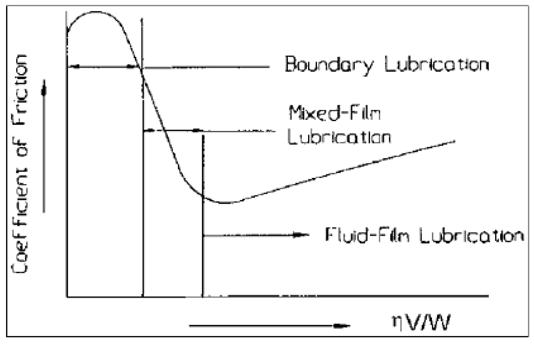
8]. This speed of sliding motion, temperature and load are simplified in this study. This material transfer that occurs during the sliding of the PCC is studied by the loss of mass of the PR and COF as a function of time. Therefore, a low overall COF, combined with a small loss of mass, is an indicator that it is a well-adjusted tribosystem. The Stribeck-type diagram can be used to model the rubbing of the PR with the cylinder liner in presence of a lubrication, as shown below [
11].
From
Figure 2, the
ηV/W factor is a lubrication parameter that can be related to the COF through the Stribeck Curve. For small values of
ηV/W, in the boundary lubrication region, the COF is high due to the decreased oil viscosity causing metal-to-metal to occur. These two metals then can rub together causing the high COF. In the mixed-film lubrication region, as the load applied decreases or oil viscosity increases, and/or sliding velocity (or linear oscillation) increases, the
ηV/W factor increases. Moreover, the COF decreases until it reaches a minimum, as shown in the mixed-film lubrication region. For higher values of
ηV/W, in the fluid-film lubrication region there is negligible asperity contact and COF increases linearly with increasing values of
ηV/W [
11].
The friction generated by the PR is significantly affected by the pressure in the cylinder throughout the four-stroke operation [
7]; cylinder temperatures and pressures contribute to corrosive wear [
9]. The cylinder is the volume in which the piston moves up and down causing the crankshaft to rotate [
12]. These factors are considered during the experiment, so that when the loss of mass and COF of each PR coating are collected, it reflects the PCC as accurately as possible during the operation cycle.
5. Discussion
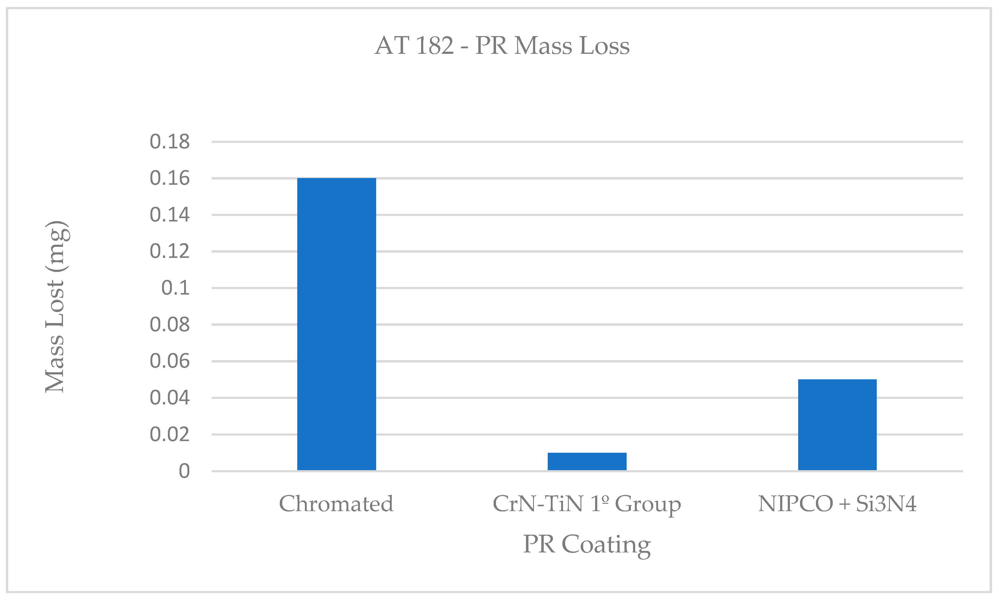
From
Figure 6, the results are as follows: the PR coating of CrN-TiN 1º Group lost the least amount of mass and the Chromium plated PR coating lost 16 times more in mass compared to the PR CrN-TiN 1º Group coating; and the PR NIPCO + Si
3N
4 coating lost 5 times more in mass compared to the PR CrN-TiN 1º Group coating. The PR coating of CrN-TiN 1º Group also has the lowest average COF. The oil bath of SAE 15W-40 provides the lubrication between the PR and the cylinder liner. This is done to help prevent the wear and yet each PR has experienced a loss of mass. As explained, over the Δ
x distance of the surface on the cylinder liner, there is a mixture of asperity points and well-lubricated points. Therefore, for each of the three PR tested, the oil film was penetrated allowing for wear to develop by the rubbing of the PR on the cylinder liner. However, it appears that the PR coating of CrN-TiN 1º Group had the least oil film penetration. This reasoning is valid, because of it having both the least loss of mass and the lowest COF among the tested PR coatings.
A very important physical property of a lubricant is its viscosity. Lubricant viscosity is dependent on the shear rate, temperature and contact pressure in the tribocontact [
15]. The SAE 15W-40 is a multigrade oil that experiences an elevated temperature of 200 °C and its viscosity can be calculated at any temperature through the Vogel Equation [
15]:
where
η is the viscosity (mPa·s, where 1 mPa·s = 1 cP) at temperature
T (°C) and
κ (mPa·s),
θ1 (°C) and
θ2 (°C) are constants. Given that
κ,
θ1 and
θ2 are constants, for a positive range of
T values
η is inversely proportional to
T. The kinematic viscosity at 200 °C estimates to 3.18 mm
2/s using this equation to model the viscometrics of the SAE 15W-40 lubricant during the experiment. In addition, multigrade oils are sheer thinning fluids [
16]. As such, the viscosity of the oil is affected by the sheer rate, which in turn is dependent on the liner oscillation speed [
7]. As the liner oscillation speed increases from static to a speed of 0.3 m/s, this may also contribute to the decrease in oil viscosity. Furthermore, the oil film thickness between the PR and cylinder liner increases with oil viscosity [
17]; then conversely given the suspected decrease in viscosity, it hints to a decrease in the oil film layer, leading to a higher chance of wear on the PR.
The Stribeck curve described earlier is a model that can be applied to further explain the results. Due to the suspected decrease in oil viscosity, along with the normal load applied and linear oscillation speed remaining constant after its initial increase, the
ηV/W factor probably falls. As this factor continues to fall, due to the eroding of the oil lubrication, the PR and cylinder liner rub together which causes wear on the PR, which also explains the loss of mass of the PRs but this model can simultaneously be used to explain
Figure 5.
In
Figure 5, for both the PR coating: CrN-TiN 1º Group and Chromium plated, there is an initial increase in COF, with the chromium plated having a larger initial peak, then an immediate decrease in COF and finally increasing slightly in COF as time goes on. The Stribeck model explains that an initial increase in COF is followed by a decrease in COF till a minimum value. The cause for an immediate increase in COF can be attributed to the PCC contact going from no friction, as there is no linear velocity at time zero, to then a sudden increase in linear velocity. This in turn can cause the sudden increase in friction but is followed by an immediate decrease in COF. The reason for this being the high contact pressure in which the COF is generated in is also related to the oil viscosity [
11]. The oil viscosity causes a reduction in friction in the initial stages, as there is enough lubrication to cause a decrease in COF. But as aforementioned, the linear oscillation is suspected to cause a decrease in oil lubrication making the COF rise eventually and cause wear to the PR. The anomaly to this trend is the NIPCO + Si
3N
4 coating, which has an initial decrease in COF and then a rise in COF as time moves on. A possible explanation is that over the contact distance, there were more pure hydrodynamic lubrication points, causing a reduction in COF. This did not last long as the COF rose quickly after, of which can be attributed to how the temperature and the linear oscillation speed change the lubrication pattern between the PR and cylinder liner. Ultimately, it did follow the trend of decreasing oil viscosity leading to PR mass loss and increased COF between the metals. The difference in the yellow and blue curve is due to running-in phenomena, which are mainly ruled by statistical events and can therefore produce significantly different COF-curves. These COF-curves depend on the many asperities that form through the actual contact between the piston ring and cylinder liner contact and how the lubricant reacts in these situations. Therefore, in this case the difference is
over-pronounced by the scale of the graph. This is necessary to make the differences in COF between the coatings clearly visible and this all takes place within the range of the COF which is smaller than 0.02.
However, the PR coating of CrN-TiN 1º Group still lost the least amount of mass. This can be attributed to the fact that CrN (Chromium nitrate) and TiN (Titanium Nitrate) are known for their good wear resistance [
18]. More specifically, CrN and TiN are applied in racing car engines, where the PCC experiences greater piston speeds [
19] due to the car travelling at high speeds during a race. For example, a Formula 1 engine V10-type experiences 37–48 m/s, whilst a regular European 2.0-L engine type Inline 4 has a maximum piston speed of up to 32 m/s [
15]. The greater piston speeds that a piston experiences in race cars indicate of the greater frictional force. Given that CrN and TiN are used for race car applications, it can be expected for them to exhibit good wear resistance, especially at a low speed of 0.3 m/s, as used during this experiment.


