3.1. Surface Structures Processed with Linear Polarization
Two types of surface textures were processed using linear polarized laser irradiation, by applying increasing peak fluence levels and various number of overscans during the laser processing. These two types are low spatial frequency LIPSS (LSFL, see
Figure 2) and hierarchical structures composed of micro-grooves and superimposed LSFL (see
Figure 3).
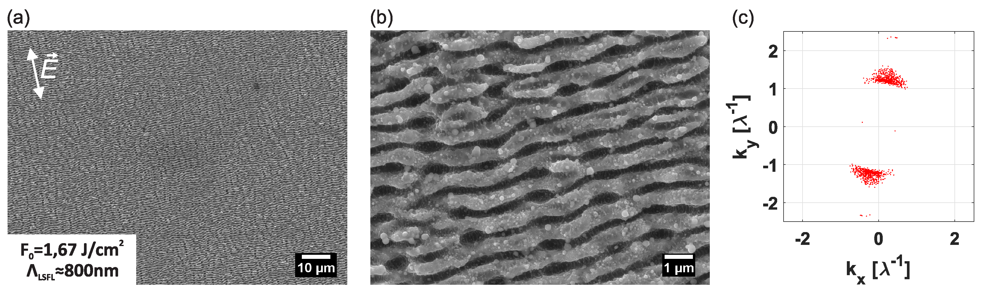
The periodicity of the LSFL in
Figure 2 was found to equal
nm and are perpendicular to the E-field of the laser polarization direction, which is typical for LSFL on metals [
23]. LSFL on the sample are spread homogeneously over the processed surface of
.
Figure 3 shows SEM micrographs of hierarchical structures processed on CoCrMo with
and various peak fluence levels. It can be observed in this figure, that with increasing peak fluence levels, the periodicity of the micro grooves increases from
m at a peak fluence level of
to
m at
. The formation of micro-grooves and micro-bumps is attributed to an increased heat accumulation during processing [
24,
25,
26].
The periodicity
nm of the LSFL in
Figure 3 was constant for all fluence levels within the fluence range studied. It is known that the LSFL periodicity increases with increasing fluence levels up to a certain fluence level, after which the periodicity does not vary with the fluence [
27,
28].
3.2. Surface Structures Processed with Circular Polarization
Triangular nanopillars (TNP), hexagonally packed, can be produced by exposing the surface to either circular polarized ultra-short laser pulses [
13], or to double-pulsed (bursts of pulses), linear cross-polarized, ultra-short laser pulses [
29,
30]. These types of structures might be preferred over LSFL for the aimed application, since TNP are symmetric in three directions, whereas LSFL are symmetric in only one direction. Because hip joints rotate with respect to the
x-,
y- and
z-axis, the tribological characteristics of the bearing should ideally be equal in any direction.
The physical phenomena behind the formation of triangular LIPSS are still under debate [
13,
29,
30]. e.g., Fraggelakis et al. [
30] proposes that the convection flow of the molten material layer as a cause for this type of LIPSS, whereas Liu et al. [
29] claims the 2D nanotriangle structures develop due to the interference of surface plasmon polaritons (SPP’s) with the incoming laser light. Since Liu et al. applied cross-polarized, time delayed double-pulses, these authors argue that the first pulse induces SPP’s and the interference with the laser light leads to transient, spatially periodic meta-gratings of a modified refractive index on the surface with a wave vector parallel to the laser polarization. Further, they claim that the second cross-polarized pulse also induces SPP’s at the surface due to surface roughness with a wave vector parallel to the laser polarization. The latter SPP then interferes with the transient refractive index meta grating of the first pulse and could diffract into two SPP’s with different wave vectors. The interference of the laser light with these three SPP’s in different directions leads to ablation of a hexagonal pattern, resulting in triangular shaped nanostructures.
Figure 4 shows SEM micrographs of surface structures processed on CoCrMo with circular polarization with
and increasing peak fluence levels. It can be observed from
Figure 4a, that LSFL with a periodicity of about
nm form at a peak fluence level of
. This structure may be an indication that the polarization is not perfectly circular, but actually elliptically polarized with the main axis perpendicular to the processed LSFL. It can also be observed in
Figure 4a, that “interruptions” of the LSFL features start to appear in the direction and the periodicity of the hexagonal shapes, see
Figure 4a and the indicated frequencies on the 2D-FFT map of
Figure 4a. Further it can be recognized when comparing
Figure 4a,b, that these “interruptions” are indeed a surface morphology “proceeding” the formation of grooves in two different directions, which then form the triangular nanopillars if the fluence is increased. At a fluence level of
, regular TNP are formed, which become less regular and less pronounced for higher fluence levels, see
Figure 4c. When comparing the laser processing conditions and groove periodicities between the hexagonal nanopillars with earlier studies (see
Table 2), it becomes evident, that the hexagonal pattern processed either with single pulses of circular polarization or with cross polarized pulses with linear polarization origin from the same physical phenomena. Hence, the physical explanation of the origin for those patterns has to apply for each case of laser processing condition listed in
Table 2. The physical explanation of hexagonal nanopillars exceeds the scope of this paper.
High spatial frequency LIPSS (HSFL) were found between the formed LSFL in
Figure 4a and the triangular nanopillars in
Figure 4b,c, with a periodicity of
nm. Liu et al. [
29] processed triangular nanopillars with two consecutive, cross-polarized pulses with a pulse duration of 50 fs and with a time delay of 1.2 ps on tungsten in air and in vacuum. In the latter study, HSFL were not observed when processing tungsten in air, but have been observed when processing tungsten at low pressures of
Pa. It was claimed, that the formation of HSFL is attributed to a slower cooling rate of the molten, liquid material layer at lower pressures. In the latter case, less air exists in the experimental environment, to transfer the heat from the molten layer to. Therefore, heat remains in the molten layer for a longer period of time and the cooling rate decreases. Thus, when the liquid material cools down, there is more time for shrinking and film fragmentation of the melt into HSFL then when processing in air. Compared to the latter study, the pulse duration of the laser used in this work, is in the order of two magnitudes larger. Hence, more heat is introduced into the lattice, which might explain the occurrence of HSFL between LSFL and triangular nanopillars when processed in air.
3.3. Surface Morphology Dimensions
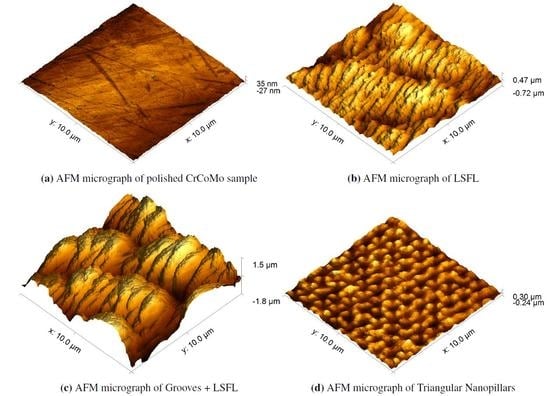
Three laser-textured surface patterns were chosen, based on their morphologies and uniformity, for the study of wettability properties, tribological performance and anti-bacterial behavior, see
Figure 5. The laser parameters used to create these structures are listed in
Table 3.
The roughness parameters of these surface textures are listed in
Table 4. As can be concluded from this table, the roughness parameters of these surfaces vary. Hence, significant differences in the functional properties (wetting, wear, biocompatibility) of these textures are expected. The higher value of
indicate that Grooves are more rough than a surface covered with only LSFL. Compared to the polished CoCrMo surface, the square root surface roughness
increases significantly due to laser-texturing. Quantitavely, 23 times
in the case of nanopillars and up to 130 times
in the case of grooves.
As can be observed in
Table 4, the dimensions of the chosen surface structures are indeed in the range of the sizes of the bacterias
S. aureus and
E. coli, which potentially gives these structures anti-bacterial properties [
3].
3.4. Wetting Properties
When anti-bacterial properties of surfaces found in nature are studied, a correlation between hydrophobicity and anti-bacterial behavior is found [
2,
31,
32]. Since LIPSS have been found to be hydrophobic [
10,
11,
12,
13,
14,
15] and also anti-bacterial [
15,
16,
17,
18], hydrophobicity is used in this paper as an indication of anti-bacterial behavior.
The three surface textures (see
Figure 5) show hydrophobic behavior compared to the untextured, mirror polished surface, which shows a water contact angle of (
, see
Table 5).
The LSFL surface is superhydrophobic for water, whereas the contact angle of the mirror polished CoCrMo substrate is hydrophilic. The surfaces denoted Grooves and TNP are both hydrophobic, but less so than LSFL, as is shown in
Table 5. The hydrophobicity of the textured surfaces is subject to variability due to the formation of oxide layers after laser micromachining over time. The polished sample will oxidize rapidly to a protective layer of CoO,
and
[
33,
34,
35,
36]. For example, it was shown by Huerta–Murillo et al. [
37], that the contact angles of laser textured titanium alloys increase over a time period of five weeks from about 90
to 130
. The contact angles in this study were measured after seven weeks for LSFL and Grooves and after 12 days for TNP. However, a positive effect of surface texturing (irrespective of morphological class) was seen on the hydrophobic behavior of the surfaces, in line with results found in literature [
12,
13,
15].
The influence of the surface roughness on the contact angle can be described by either Wenzel [
38], where it is assumed that the total surface will be in contact with the liquid, or by Cassie [
39], where different materials or a combination of trapped air and a solid will be in contact with the liquid. In case of Wenzel the relation between the apparent contact angle (CA)
and the intrinsic CA
is given by
where
is the ratio between the true surface area and the projected area. In case of hydrophilic surfaces an increase of the roughness will result in a decrease of the CA and in the case of hydrophobic surfaces an increase of the roughness will result in an increase of the CA.
In case air might be trapped due to surface morphology the contact angle according to Cassie–Baxter [
39] is defined as
In this equation, is the apparent contact angle, f is the fraction of the projected area of the surface that is wet by the liquid and is the roughness ratio of the wet area. This shows, that an increasing amount of trapped air, which means a smaller ratio f, will lead to an increase of the apparent contact angle.
This indicates that the measured contact angles on the CrCoMo samples due to laser processing can be explained by the increase of the ratio between the real surface area and the projected area
and a reduction of the wetted area due to LIPSS [
40,
41]. Nonetheless, the contact angles are highly dependent on the formation of additional oxide layers. Interpretation of the origin of the hydrophobic properties would require a more thorough study of this surfaces.
3.5. Tribological Properties
The measured coefficient of friction (CoF) of the textured CoCrMo surfaces are listed in
Table 6. The CoF of TNP with the hexagonal TNP is significantly lower than those of LSFL and Grooves. The friction coefficient of polished CoCrMo with 0.5 N (18 MPa), 11 mm/s and BCS lubricant was
. The friction coefficients of the textured surfaces are thus significantly higher than the CoF of the polished surface, due to the surface topograhphy changes.
Figure 6 shows SEM micrographs of the LSFL structure after the wear test. From this figure it can be observed that the surface morphologies on the CoCrMo surface remain intact during the given wear test. After 104 min of sliding the PE sphere over the LSFL textured surface with a 18 MPa load, 11 mm/s speed and BCS lubricant, the PE ball had a volume loss of
. This is nearly 9.5% of the total sphere volume. Hence, it can be concluded that LSFL cannot be used as a bearing surface of a hip joint, since in the end of high loading, it reduces the durability of the hip joint significantly. The other two textures lead to noticeably less wear on the PE ball, see
Table 6. The CoF of LSFL was also higher than that of Grooves and TNP. However, the difference between the CoF LSFL and Grooves is much smaller than the wear PE experiences against LSFL and Grooves. The fact that LSFL show a higher hydrophobicity (see
Table 5) may influence the wear rate as well. High friction in a joint will lead to more heat generation, which may cause performance degradation of the joint. However, no maximally defined CoF is stated for a hip joint. The wear recorded for TNP is actually very close to that found on the polished surface.
The wear conditions of the UMT, which are 18 MPa, 11 mm/s, reciprocal movement, are not comparable to the wear conditions in a natural hip joint, approximately 7.8 MPa and 21 mm/s during normal gait and rotational movement in all directions [
21]. Since the surface structure TNP shows a periodicity in three directions (see
Figure 4), instead of one in the cases of LSFL and Grooves, and also shows the lowest CoF and PE wear very close to the polished surface, TNP is the most promising candidate for a potential anti-bacterial surface structure on an artificial hip-joint.
3.6. Biocompatibility
Lutey et al. [
15] showed that LSFL and TNP performed best on anti-bacterial properties regarding
E. coli and
S. aureus on stainless steel. A bacterial count reduction of 99.8% and 99.2% was found for
E. coli and 84.7% and 79.9% was found for
S. aureus, for the LSFL and TNP, respectively. Grooves (in [
15] defined as Spikes) on the other hand, do not show improvement in anti-bacterial properties. However, to estimate the leaching of hazardous elements of the CoCrMo alloy into the human body, LSFL textured CoCrMo samples were used to perform a leaching test.
Release of Cobalt (Co) ions from the CoCrMo substrate may have an adverse affect on the patient’s health. The Medicines and Healthcare products Regulatory Agency recommended a
g/L threshold. Concentrations above that threshold can be toxic for the patient [
42]. Due to the increased surface area of the textured samples, when compared to the polished samples, textured samples may cause a higher ion release rate of Co and Ni ions. Chromium (Cr), Molybdenum (Mo) and Nickel (Ni) are also toxic in certain concentrations, but to the best of the authors knowledge no medical standardized regulations exist on acceptable concentration levels. The release of ions can be studied by means of a leaching experiment.
To that end, polished CoCrMo as well as LSFL textured CoCrMo samples were immersed in simulated body fluid (SBF, see
Section 2.2.5) for nearly four weeks. Ion release was measured after 1, 7, 21 and 26 days. All samples were analyzed for the presence of Co, Cr, Mo and Ni elements by means of atomic emission spectroscopy analysis. No significant concentrations of Cr, Mo and Ni were found for any of the samples. Traces of Co were found in the SBF samples of the polished and the textured CoCrMo samples, see
Figure 7. A gradual release of Co can be observed during the first two weeks for both polished and textured CoCrMo. After one day of immersion, the Co ion concentration is slightly higher for textured CoCrMo. Interestingly, there is no significant difference between the textured and untextured sample observed after one week and three weeks of immersion. After two weeks of immersion a larger Co concentration is found for polished CoCrMo and after four weeks of immersion the textured samples give a higher concentration,
ppb vs.
ppb. It was expected that the concentration of cobalt in the SBF would increase in time as more and more cobalt leaches from the surface into the fluid, until the equilibrium state is reached. The decrease in cobalt concentration of the untextured sample after 14 days could be explained by a change in pH due to a change in ion concentration in the SBF. The pH change could influence the equilibrium of Co ions. No precipitation of any element was observed at any point during and after the experiment. Unfortunately, the pH was not measured after the experiment. The difference in cobalt concentration after four weeks of immersion between polished and textured CoCrMo could be explained by the difference in surface area. According to Leyssens et al. [
42], levels of Co lower than
g/L will not cause health complications for individuals. The levels of Co in this study measured during 26 days of immersion, are well below this threshold. In the body the CoCrMo surface will be slightly larger. However, in the patients body, larger amounts of bodily fluids are present, and the human body does process low concentrations of Co [
43]. However, it is questionable if this test can be compared with levels measured in patients. There are many factors which effect the leaching behavior of surfaces. To the best of our knowledge, no research on leaching of CoCrMo in SBF or similar circumstances has been conducted so far.


