1. Introduction
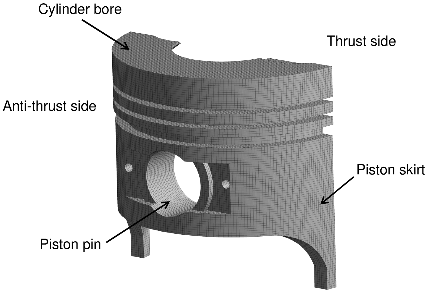
Inside the combustion chamber of the engines, there is a clearance between the cylinder liner and the piston skirt, which allows the piston to move in a lateral direction. Despite the presence of the piston rings, this type of movement is not eliminated. The analysis of the lateral movement is of utmost importance since it allows us to understand the friction processes present in the piston, which constitute 30–50% of the total mechanical losses in engines [
1]. Additionally, the clearance enables the piston to collide with the cylinder liner, generating unwanted vibrations and shocks in the cylinder block.
To transform the reciprocating movement of the combustion chamber into the rotational movement of the power shaft in internal combustion engines, the mechanism formed by the crankshaft, connecting rod, and piston is used [
2,
3,
4]. Proper movement of this mechanism requires the presence of clearances, which are located at the connecting rod to the crankshaft connection, the connecting rod, and piston pin connection, and between the cylinder liner and the piston skirt. However, the presence of clearances and the contact forces between the cylinder liner and the piston cause lateral movements that cause the piston to tilt [
5,
6,
7,
8]. This particular movement is referred to in the literature as the secondary movement of the piston. The presence of this movement in the piston causes a negative effect on the engine due to the appearance of impacts and/or unbalanced hydrodynamic forces that can generate noise and vibrations in the engine body and in the connections of the crankshaft mechanism, connecting rod, and the piston [
6,
9,
10]. Due to the above, the study of the clearances in the connecting rod connections with the piston and the crankshaft is an important condition that must be considered to analyze the dynamic behavior of the mechanism.
Several experimental investigations have focused on the study of the secondary movement of the piston [
11,
12,
13,
14,
15,
16]. The obtained results show that the piston impacts the cylinder liner an average of three times when completing a cycle of the combustion process. The strongest impact is located at the top dead center during the compression stroke [
13,
17,
18]. Additionally, the results show that the piston tends to tilt during the expansion stage [
14,
19]. Each of the conditions described above is affected by clearances between the cylinder liner and piston and between the end connections of the connecting rod.
Additionally, research has been conducted focused on theoretical models to describe the secondary movement of the piston [
20,
21,
22,
23]. In these types of studies, the eccentricities of the piston with the cylinder liner are generally analyzed using moment and force equations. The presence of these moments and forces is a consequence of the pressure inside the combustion chamber, the inertia of the elements of the mechanism, the friction on the cylinder walls, and the impacts on the piston. The use of these theoretical models allows predicting the dynamic behavior of the piston. Tan and Ripin [
22] developed a nonlinear model to describe the lateral and rotational motion of the piston. The research analyzed the secondary movement of the piston and its effect on engine vibration, which were validated by experimental results. Additionally, Tan and Ripin [
24] studied the contact that occurs between the cylinder liner and the piston skirt due to the inclination and secondary movement of the piston. Murakami et al. [
14] investigated an analysis methodology for secondary piston motion by adding structural analysis and multibody dynamic analysis. The proposed methodology was compared with results obtained by measuring the secondary movement, the tension in the piston skirt, and the vibration. In addition, later investigations involved the effects of surface roughness and lubrication conditions.
Meng et al. [
25] analyzed the effects of vibration on tribological performance and lateral piston movement. The obtained results indicate that the vibration produced in the combustion chamber can be reduced by increasing the damping, mass of the cylinder, and rigidity. Narayan [
26] developed a model of secondary piston movement, in which the dynamic characteristics of the cylinder liner and piston skirt were analyzed. Obert et al. [
27] investigated the influence of temperature and the amount of lubricating oil on the piston skirt and cylinder. Mazouzi et al. [
28] studied a numerical model to describe the secondary motion of the piston. The objective of the model is to observe the effect of the design parameters of the piston on the contact characteristics between the cylinder liner and the piston skirt. Results show that clearance changes can reduce piston strokes and friction. Fang et al. [
29] developed a model to describe the lubrication in the piston skirt and the movement of the piston-connecting rod–crankshaft system. The model used allowed for the analysis of the tribological behavior of the piston. Meng et al. [
30] studied the influence of inertial forces on the lubrication film, including pressure changes in the film, hydrodynamic forces, and lateral movement of the piston.
Due to the importance of secondary piston motion analysis, researchers continually seek to expand the complexity of theoretical models to improve their estimation. One of these improvements is to consider the inertia of the connecting rod. Zhang et al. [
31] implemented a mathematical model to describe the connecting rod–piston–crankshaft system. The model used considers the secondary movement of the piston and the force of the connecting rod. The results indicate that the center of mass is a significant parameter for the design of the connecting rod. Meng et al. [
32,
33] studied the dynamic movement of the piston, friction losses, and the lubrication film, taking into account the inertia of the connecting rod. The results showed that the inertia of the connecting rod significantly affects the dynamics of the piston, especially under high-speed conditions. Zhu et al. [
34] analyzed the stress distribution in the connecting rod body, considering the effects of the lubrication film.
Another key factor to consider when studying the secondary movement of the piston is the deformation it experiences. The research focused on piston skirt lubrication analysis shows that piston deformation is an important factor in analyzing the friction characteristics applied to the engine body. Pelosi and Ivantysynova [
35] analyzed the influence of heat flow and thermal deformation on the contact of the cylinder and the piston skirt. Ning et al. [
36] developed a lubrication model in the piston skirt, considering the deformations of the piston. Since the deformation of the piston affects the lubrication conditions, it is necessary to consider it for the analysis of the secondary movement of the piston. However, generally, the deformations experienced by the piston are ignored for the development of the dynamic model. Additionally, research in the literature indicates that connecting rod clearances influence the dynamic behavior of the piston [
37,
38,
39,
40]. Despite the above, the clearances in the connecting rod connections are not normally considered in the dynamics of the piston movement.
The objective of the present investigation is to develop a mathematical model for the analysis of secondary movement of the piston that allows including the existing deformation in the piston skirt and the influence of the clearances in the connecting rod bearings in order to increase the complexity of the model to improve its estimates. For the study, the geometric of the crankshaft-connecting rod–piston system of a single-cylinder diesel engine is taken as a reference. The deformation model of the piston was carried out by means of a symmetric finite element model (FEM), which was integrated into the mathematical model of the piston. MATLAB software is used for the development of model simulations. The developed model is used to analyze the movement of the piston, the slap force on the piston skirt, the effect of the secondary movement of the piston on the connecting rod, and the influence of clearances on the connecting rod bearings and between the cylinder liner and the piston skirt.
The purpose of the foregoing is to develop a methodology to analyze in detail the characteristics of the secondary movement of the piston, which can be used as a tool for the diagnosis of slap forces, noise, and vibrations in the combustion chamber. The development of this type of tool is useful for the design and/or modifications to the engine in such a way that it facilitates the search for power reductions due to friction in the chamber, greater durability of the components, and lower acoustic emissions.
3. Results and Discussion
3.1. Experimental Validation
To determine the validity of the mathematical model used in the present study, a comparison is made between the results obtained by means of the model and those obtained by means of experimental tests. The experimental test bench used is shown in
Figure 9.
The combustion pressure curve for this operating condition is shown in
Figure 10. The experimental data are recorded with a pitch length corresponding to 2 degrees of the crank angle. The data from the sensors located on the piston are connected to a data acquisition system and post-processing software. During engine operation, variations from cycle to cycle may occur as a result of changes in combustion chamber pressure. Additionally, the irregularity of the lubrication system due to the splash mechanism in the cylinder liner causes variations in the lubrication film that affect the damping between the piston skirt and the cylinder liner. As a result, the data are recorded for 30 cycles of the engine in order to minimize errors due to the repeatability of the measurements.
The measurement of the crankshaft rotational speed was carried out by means of an angle sensor (Beck Arnley 180-0420, Nashville, TN, USA). Using a piezoelectric sensor (KISTLER type 7063-A, Winterthur, Switzerland) installed inside the combustion chamber, the combustion pressure is recorded.
The technical characteristics of the engine used are shown in
Table 2. Four eddy current sensors located on the edges of the piston skirt are used to monitor the piston slap behavior (see
Figure 11). The sensors are embedded in the piston and are connected through a link system that runs through the connecting rod–crankshaft system until it reaches a signal amplifier. By means of the alternator connected to the engine, rotation speed and a constant load of 3600 rpm and 9 Nm are established due to these are the main operating conditions. This is due to the fact that in this condition of torque and rotational speed, maximum efficiency is produced in the stationary diesel engine.
Table 3 shows the instruments used to measure the magnitudes of pressure in the cylinder chamber and the crankshaft angle. To measure the clearance between the piston skirt and the cylinder liner, a non-contact gap sensor (Model HPC-500-V, Ayer, MA, USA) was selected, with high thermal resistance (800 °C) and a resolution of 0.25
.
Figure 12 shows the comparison between the clearances between the piston skirt and the cylinder liner obtained through the simulation of the model and the experimental results.
The obtained results show that both curves maintain the same trends both in the upper part and in the lower part of the piston. In the case of measurements of clearances at the top of the piston, an average error of 14% was observed between the model estimates and the experimental data (see
Figure 12a). However, there are regions throughout the combustion cycle in which a greater distance is observed. This may be the result of the sum of factors such as sudden pressure variations in the chamber, changes in the thickness of the lubrication film, and alteration in the properties of the lubricant.
For the measurements of the clearances at the lower of the piston, an average error of 18% was observed between the model estimates and the experimental data. In a similar way to the previous case, regions of separation were observed in which a greater difference between the model and the experimental one can be seen. However, for the lower of the piston, the separation regions are larger when compared to the results in
Figure 12a. This greater separation can be attributed to surface irregularities present in the lower part of the cylinder liner.
In general, the trend of the model estimates and the experimental data, and the percentage of error, are similar to those reported in the literature [
13].
3.2. Characteristics of Piston Motion
In
Figure 13 and
Figure 14, the characteristics of the secondary motion of the piston during a combustion cycle are described.
Figure 13 shows the lateral displacement experienced by the piston and the velocity of this displacement. The positive and negative displacements shown in
Figure 13a demonstrate that the piston performs a fluctuating motion in the lateral direction while completing the stroke of a combustion cycle. This can cause the appearance of impacts of the piston skirt with the cylinder liner. The maximum lateral displacement of the piston is 14
.
The velocity of the lateral motion is shown in
Figure 13b. It was observed that the velocity peaks are located in the vicinity of the crankshaft angles 0°, 180°, 360°, 540°, and 720°, which correspond to the location of the top and bottom dead centers of the piston. This behavior is in agreement with the research presented in the literature [
13,
48]. Lateral velocity analysis shows that six changes in the direction of secondary piston movement occur during the combustion cycle. The maximum lateral velocity is 0.13 m/s, which is located between an angle of 357° and 370°.
The piston tilting angle is shown in
Figure 14. The results show that the piston performs a rotary movement in a range of
to
rad. The maximum angular velocity reached was 3.75 rad/s, obtained in the final stage of the compression process.
The fluctuating motion in the lateral direction of the piston described in
Figure 13a can be related to the forces present in the connecting rod bearing
.
Figure 15 describes the values taken by the force
throughout the combustion cycle.
It is observed that the force
takes positive and negative values in different ranges of crankshaft angle. The change in the direction of the force forces the piston to move to the right or left side of the cylinder liner, causing the lateral movement described in
Figure 13a. Additionally, it is observed that the force
experiences high fluctuations for the angles 0°, 180°, 360°, 540°, and 720°, which is in agreement with the regions of perturbation of the lateral velocity and the velocity of the inclination angle shown in
Figure 13b and
Figure 14b. These fluctuations are a consequence of the impact of the piston with the cylinder liner. The above results show the close relationship between the secondary movement of the piston and the force on the connecting rod bearing.
3.3. Piston Slap Force Analysis
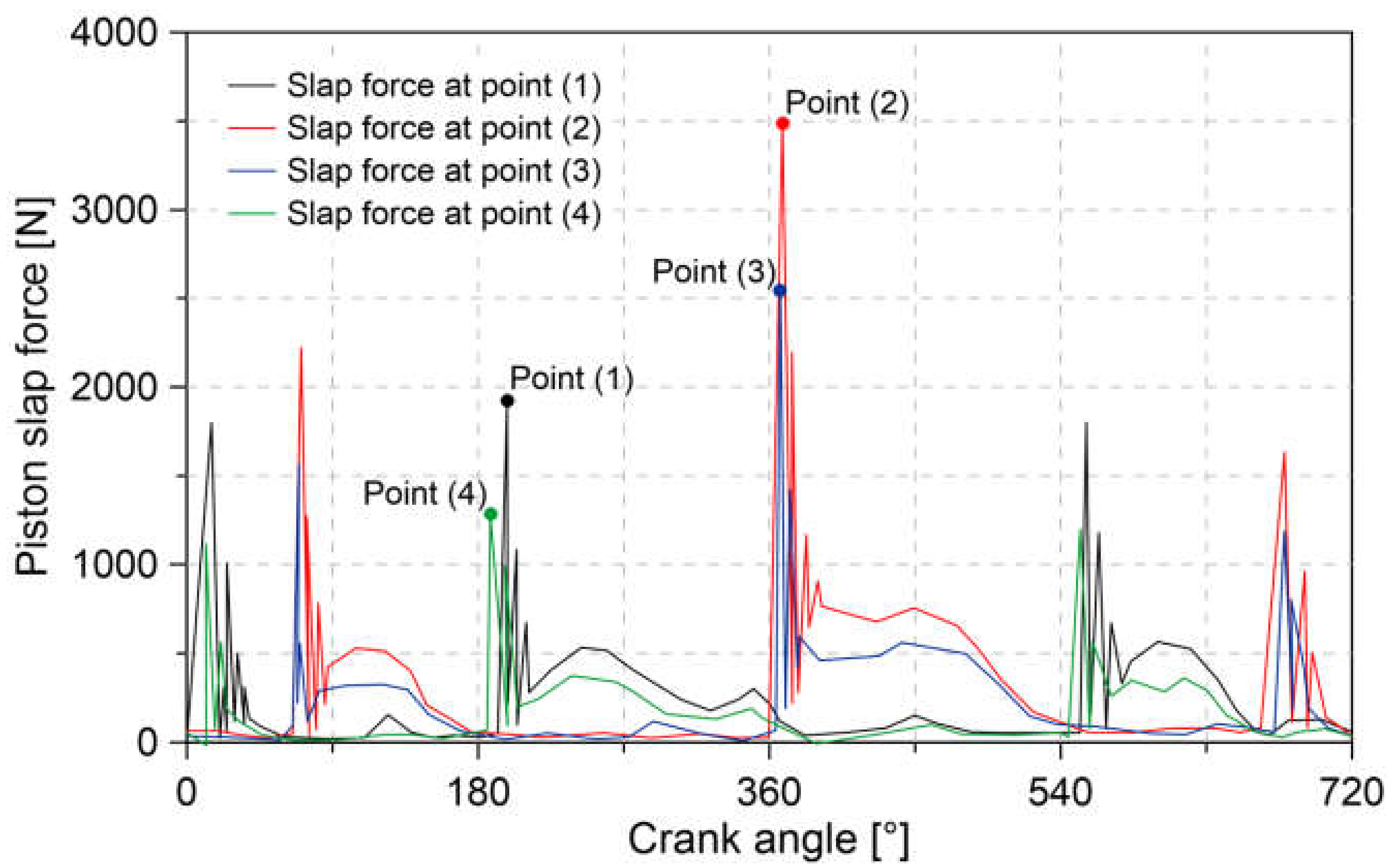
Figure 16 shows the slap force for the four endpoints of the piston (see
Figure 2) during the combustion cycle.
It is observed that the impacts on the cylinder liner begin at approximately an angle of 30°, followed by a second sequence of impact located approximately at 45°. The results indicate that the intake and exhaust stages of the engine experience slap forces similarly. The greatest slap force is located at point (2) during the compression stage, which reaches a magnitude of 3480 N. At points (1), (3), and (4), a maximum slap force of 1900 N, 2540 N, and 1275 N, located at 200°, 367°, and 187°, respectively, is observed.
The analysis of the slap force on the piston can be used as a tool for indirect diagnosis of tribological conditions present in the combustion chamber. The increase in slap force is associated with inefficient lubrication between the piston skirt and the cylinder liner. This diagnosis can be made easier since the slap force is associated with engine noise, as indicated in the literature [
49].
The conditions of the piston endpoints (1, 2, 3 and 4) can be affected by the position of the piston pin. To study this condition, variations were made in the position of the pin piston through changes in the distance parameter Cp (see
Figure 1). The obtained results are shown in
Figure 17.
Figure 17 shows the changes in lateral displacement and velocity of point (2) for different values of Cp. The results show that for a positive value of Cp, the piston tends to tilt towards the thrust side, while a negative value causes an inclination towards the anti-thrust side. This difference is located for an angle between 360° and 380°. Similar behavior is observed when evaluating the displacement velocity. In this case, the results indicate a reduction and an increase in velocity for the positive and negative value of Cp.
The change in the movement of point (2) due to the variation of the distance Cp is more noticeable when considering the angle of the inclination of the piston. The changes of this angle are shown in
Figure 18.
The obtained results show that when using the positive value of Cp, the angle of inclination takes positive values. An opposite case occurs when considering a negative value of Cp. Therefore, the change in the angle of inclination is what causes the piston to move towards the thrust side or anti-thrust side of the cylinder liner.
To analyze the effect of the distance parameter Cp on the slap force, the behavior of the slap force applied at point (2) during the combustion cycle is analyzed. The obtained results are shown in
Figure 19.
The results of
Figure 19 indicate that the magnitude of the force tends to increase if the distance Cp takes a negative value. However, for a positive value of Cp, the slap force is reduced. For the Cp values of −0.4 mm and 0.4 mm, an increase and a reduction of 2% and 3% was observed in the maximum slap force compared to a condition with no offsets (Cp = 0). This behavior is because the change in the direction of the distance Cp causes a reduction or increase in the separation distance between the point (2) and the cylinder liner.
3.4. Effect of Secondary Piston Motion on the Connecting Rod
To analyze the influence of secondary piston movement on the forces of the connecting rod bearings, two different conditions are established in the clearance between the piston skirt and the cylinder liner (Cpc). For this, two values are selected in the Cpc parameter of 0 and 14 m. The no-clearance condition (Cpc = 0) is used to eliminate the secondary movement of the piston. This is in order to be taken as a reference condition in the analysis.
Figure 20 shows the small end bearing force. The results show that both curves present a similar trend. The difference lies in a series of disturbances throughout the combustion cycle. Each of these disturbances are a consequence of the impact forces on the piston skirt caused by the established clearance (Cpc = 14 um). It is observed that the presence of clearance can cause an increase of 1000 N in the bearing force.
Similarly,
Figure 21 shows the big end bearing force. The results show that the presence of the impact forces causes disturbances in the bearing forces. A similar trend to the obtained results in
Figure 20 is observed. However, the increase in bearing force is 550 N.
The force disturbances in the connecting rod bearings shown in
Figure 20 and
Figure 21 are a direct consequence of the contact between the piston skirt and the cylinder liner caused by the clearance Cpc = 14
m. The main regions of disturbance are located in both cases at a crankshaft angle of 180°, 360°, 540°, and 720°, respectively. This distribution is due to the change in lateral direction experienced by the piston at these locations due to secondary movement, which is in accordance with the results of
Figure 13.
3.5. Effect of Clearance on Secondary Piston Motion
Figure 22 depicts the change in lateral displacement and tilt angle for different clearance conditions between the cylinder liner and piston skirt (Cpc).
The results show that, for the three values of clearances evaluated, the displacement and angle of inclination curves present similar behavior. However, increasing the clearance Cpc causes an increase in the displacement and an angle of inclination, which is a consequence of the greater travel that the piston must make. The increase in the distance traveled due to the increase in Cpc implies that the piston has a longer time to reach higher accelerations both in its lateral and angular movement. The increase in acceleration can be verified by observing the behavior of
Figure 23.
The results of
Figure 23 show that for a distance of 25
m, 50
m, and 100
m in the clearance Cpc, a maximum lateral acceleration of 0.25, 0.58, and 0.86 m/s
2 is obtained, respectively. In the case of angular acceleration, a maximum value of 1.55, 3.02, and 4.87 rad/s
2 was observed.
The effect of increasing clearance Cpc on connecting rod bearing forces can be seen in
Figure 24.
The results show that the higher accelerations in the pin piston due to the increase in the clearance Cpc cause higher impact forces on the connecting rod bearing. A maximum force in the x direction of 2963 N, 4321 N, and 6469 N was observed for a distance of 25 m, 50 m, and 100 μm in the Cpc clearance, respectively.
3.6. Effect of Connecting Rod Clearance on Secondary Piston Motion
To evaluate the effect of the connecting rod bearing clearance (Cjb) on the secondary movement of the piston, different values of Cjb were taken in a range of 0–60
For each one of the Cjb values, the acceleration of the lateral motion of the piston was analyzed during a complete cycle. The obtained results are shown in
Figure 25.
It was observed that throughout the combustion cycle, there are different types of trends in lateral acceleration when modifying the Cjb values. In general, a critical value of Cjb is shown, which, when exceeded, produces an increase in lateral acceleration. The behavior described above can be observed for a crankshaft angle of 0–45°. Starting from a slack value of Cjb = 10 and Cjb = 25 , the magnitude of the acceleration constantly increases for a Cpc value of 25 , 50 and 100 , respectively. However, for the section of the combustion cycle between 360° and 450°, changes in Cjb do not influence the lateral acceleration of the piston. The above indicates that the impact forces on the piston during the expansion stage are independent of the clearance in the connecting rod bearing (Cjb).
Table 4 shows the limit values of the clearance Cjb for the different ranges of the crankshaft angle and different values for the clearance Cpc.
The values described in
Table 4 indicate the maximum distance that can occur in the clearance Cjb before the lateral acceleration of the piston increases considerably. This could lead to increased impact forces, thus causing vibration and wear problems in the engine. Additionally, the limit values can be used to quantify the wear of the connecting rod bearings and quantify the gravity caused by the secondary movement of the piston.
The analysis of the limit value of Cjb can also be applied considering the primary movement of the piston.
Table 5 shows the values of the piston acceleration for different clearance conditions: Cjb and Cpc.
Table 5 presents a limit value in the clearance Cjb of 25
for the range of Cpc values analyzed. A value greater than Cjb = 25
causes an increase of approximately 50% in the primary acceleration of the piston.
3.7. Effect of Elastic Deformation of the Piston
The elastic deformation of the piston skirt has an influence on the change of the lubrication thickness (see Equation (21)). This change in thickness caused by the deformation of the piston produces a variation in the piston clearance and, therefore, differences between the estimated slapping forces and, in general, changes in the characteristics of the movement of the piston.
To observe the effect of the elastic deformation of the piston, a comparison is made between the model with deformation and without deformation (d = 0 in Equation (21)). The obtained results are shown in
Figure 26.
Figure 26 shows a comparison of the lateral displacement experienced by point (2) (see
Figure 3) for the two conditions studied. The results indicate that the model without deformation estimates an increase of 50% in the maximum value of the displacement compared to the elastic model of the piston. This difference could cause an overestimation in the dynamic forces present in the piston-connecting rod–crankshaft system.
4. Conclusions
In this study, a mathematical model is carried out in order to analyze the secondary movement of the piston. The model considers deformation due to hydrodynamic pressure and contact pressure in the piston skirt, as well as the influence of clearances in the connecting rod bearings.
The obtained results show that the piston experiences a movement in the lateral direction and an inclination throughout the combustion cycle. In total, six directional changes are recorded in the secondary piston movement with lateral velocities that can reach a maximum of 0.13 m/s. In the case of the angular velocity of the lean angle, the results show maximum velocities close to 4 rad/s. Speed trend analysis indicates that maximum values are reached approximately the top dead center during the compression. The lateral and angular movement of the piston during its travel causes the appearance of impacts on the piston skirt with the cylinder liner. These impacts produce fluctuations in the hydrodynamic forces of the connecting rod bearings in the form of spontaneous increases in force of approximately 500 N.
Analysis of the slap force at the four ends of the piston skirt shows that the range of the maximum magnitudes of the forces is between 1900 N and 3480N. The maximum value of the slap force occurs during the compression stage and is located at the upper ends of the piston skirt. The slap force tends to increase when there are changes in the direction of the parameter Cp. The results indicate that this change in direction can cause a 2% increase in maximum slap force.
The increase in the clearance between the piston skirt and the cylinder liner (Cpc) causes a greater lateral displacement and an increase in the angle of inclination of the piston, which causes an increase in the lateral acceleration of the piston that causes the presence of impact forces of greater magnitude. The results indicate that a 25 increase in clearance Cpc can cause the maximum values of the lateral and angular acceleration of the piston to double in value. This increase in acceleration causes a 46% increase in the force of the connecting rod bearings. This behavior shows that the developed model can be used to diagnose the appearance of wear on the cylinder liner. Additionally, the results show that the expansion of the clearance Cpc produces fluctuations in the hydrodynamic force of the big and small bearing of the connecting rod by an average of 775 N.
The analysis of the change in the connecting rod bearing clearance (Cjb) shows that there are critical values in relation to the clearance Cpc, which, when exceeded, produces a constant increase in the lateral acceleration of the piston. This type of trend can also be found by analyzing the primary acceleration of the piston. The results allow us to identify that from a clearance Cjb = 25 there is a drastic increase in the primary acceleration of the piston. The above behavior can be used to diagnose the conditions of the engine piston, which protects the engine from unwanted vibrations, wear on the connecting rod bearings and wear on the cylinder liner.
Consideration of the elastic deformation of the piston in the model used allows an adequate estimate to be made for the lateral movement of the piston, which affects the dynamic forces in the piston-connecting rod–crankshaft system. It is observed that by not considering the deformation of the piston, there are deviations close to 50% in the lateral displacement of the piston.
Future research on the topic developed aims to improve the instrumentation used for measuring piston clearance. This in order to obtain more accurate results and reduce intrusion on the engine. Additionally, the complexity of the model can be improved, considering other types of deformations, such as those produced by the pressure of the combustion gases at the top of the piston and the thermal deformations of the cylinder bore, which will improve the accuracy in the clearance estimate.
Among the challenges for the application of the methodology used is to guarantee an adequate temperature level in the combustion chamber to avoid damage to the gap sensors. This can be a limitation to evaluate the most critical operating conditions in higher power engines. Additionally, for the comparison between the model estimates and the experimental results, it is necessary to monitor the lubricant temperature since this parameter considerably influences its properties.


