Article

Tensile Behavior and Formability of Pre-Painted Steel Sheets

by
Archimede Forcellese
1,
Tommaso Mancia
1 and
Michela Simoncini
2,*
1
Dipartimento di Ingegneria Industriale e Scienze Matematiche (DIISM), Università Politecnica delle Marche, Via Brecce Bianche, 60100 Ancona, Italy
2
Università degli Studi eCampus, Via Isimbardi 10, 22060 Novedrate, Italy
*
Author to whom correspondence should be addressed.
Metals 2020, 10(1), 53; https://doi.org/10.3390/met10010053
Submission received: 1 November 2019 / Revised: 3 December 2019 / Accepted: 25 December 2019 / Published: 27 December 2019

Abstract

:
The present work aims at studying the tensile behavior and formability of pre-painted steel sheets. To this purpose, uniaxial tensile and hemispherical punch tests were performed in order to analyze the deformation behavior of pre-painted sheets under uniaxial stretching and biaxial balanced stretching conditions, respectively. Tests were interrupted in order to obtain different strain levels until fracture; at each strain level reached, the occurrence of superficial damages on the paint coating was detected; thinning of the different layers of the pre-painted sheet was also measured. It was observed that the degree of damage on the paint coating depends on the loading condition; in particular, under uniaxial stretching, the paint coating is able to follow the steel sheet during deformation up to the onset of the necking, whilst, under biaxial balanced stretching, coating exhibits superficial damages before fracture of the sheet.

1. Introduction

The modern white goods industries widely use steel sheets owing to their excellent attitude to undergo forming operations in order to give shape to covers of household appliances, such as washing machines, boilers, ovens, lighting fixtures, refrigerators, air conditioner outdoor units, etc. [1]. The traditional approach in the manufacturing of these parts involves a series of metal forming and cutting processes; subsequently, they are subjected to painting processes, such as spray-painting, galvanic, powder-painting, etc., which allow one to apply a paint coating film on steel sheets [2,3].
Technological innovations have led to significant changes in the production processes of white goods that do not require welding, by performing the sheet-painting before forming and cutting operations. As reported by Escobar-Saldívar et al. [4], it has been shown that pre-painting, carried out at the steelworks immediately after rolling, leads to an increase in the efficiency of the production process. As a matter of fact, pre-painted steel sheets can be very convenient for appliance manufacturers because they can buy pre-painted sheets from external suppliers without the need of an in-plant painting process after sheet forming processes, and can eliminate costs associated with both the painting process and stringent disposal requirements for paint chemicals. In addition, pre-painted steel sheets provide benefits of a faster and simpler operation, without problems related to the worker protection and environmental/pollution, and allow savings in equipment maintenance, inventory, and other costs associated with operating in-plant painting lines.
Damage of coating and adhesive bond between coating, primer, and metal sheet must be avoided during manufacturing processes [2]. As a consequence, the paint on a pre-coated sheet must have the ability to undergo manufacturing processes such as plastic forming operations without generating damages, unlike conventional post-painted steel sheets that are coated after they have been deformed and cut to their final shape. Unfortunately, forming processes of pre-painted sheets are strongly related to the formability required to the coating since the paint could not perfectly follow the sheet under deformation. It is desirable that the paint deforms as the underlying steel sheet, avoiding the occurrence of superficial aesthetic damages on the top coat before fracture of metal sheet.
Thus, understanding the paint coating durability during plastic deformation of pre-panted sheets is a fundamental aspect in order to avoid coating damage in metal-forming processes in which plastic deformation plays a significant role. Some studies on the coating behavior of pre-painted steel sheets have been carried out. Lange et al. [5] have shown that the resistance to scratches exhibited by pre-painted sheets mainly depends on their ductility. Prosek et al. [6] have based their research on the analysis of the phenomenon of blistering of coil-coated materials. Very few studies on the deformation capability of pre-painted sheets are available in scientific literature. Moon et al. [7] investigated the formability in deep drawing of galvanized steel sheets, pre-coated with different synthesized polyester resins, demonstrating that it is affected by the maximum strain of paint film and elastic strain energy stored in paint films after deformation. Behrens and Gaebel [8] studied formability of an anti-fingerprint clear coating on satin stainless steel sheet and defined the coating specific forming limit curve. The thermal effect on the survivability of polyester coated steels in ironing was investigated by Huang et al. [9] who demonstrated that coating integrity was affected by processing conditions.
In this framework, the present investigation aims at studying the behavior of a pre-painted steel sheet under uniaxial stretching and biaxial balanced stretching conditions which represent typical straining states occurring in metal-forming operations of complex parts. To this purpose, both tensile and hemispherical punch tests were carried out; they were interrupted at different strain levels in order to evaluate the elongation capability and formability of both paint coating and steel sheet. At each strain level, damages on the paint coating were detected and thinning of the different layers of pre-painted sheets was measured and analyzed.

2. Material and Experimental Methods

2.1. Material

The material investigated is schematically shown in Figure 1. It consists of the low carbon steel sheet Z100 for cold forming, zinc-coated by means of continuously hot-dip coating process according to the ASTM A653/A653M-19a and EN 10346: 2015 standard [10,11]; its thickness is equal to about 0.88 mm. A two-sided coating system was used, as top and back covers respectively.
Zinc coating provides a good substrate for painting when the surface is correctly prepared. First, a degreasing phase was carefully carried out to remove impurities from surfaces to be painted. Degreased sheets passed to the rinsing stage; in particular, two separate rinsing baths were used to prevent chemical transfer from degreasing bath to phosphating one. Then, the proper pre-treatment by the immersion iron-phosphating technology was performed in order to achieve adhesion of the coating on the steel surfaces and reduce corrosion even after scratches on the paint: sheets were treated 5–10 min at about 50 °C. After passivation treatment for 30–45 s, the iron-phosphating process ends with a drying phase at maximum temperature of about 130 °C. Then, a 5-μm thick epoxy-polyester resin layer was laid down as top and back primers, to take advantage of the fine anti-corrosion function of the resin; a silicone-modified polyester layer, 35 μm in thickness, was used as top finishing film for its excellent weathering resistance. The final thickness of the sheet after the pre-painting operation was about 0.925 mm. Figure 2 shows the different layers of the pre-painted steel sheet. Tolerances of the coated steel are in accordance with the EN 10143: 2006 standard guidelines [12].

2.2. Test Methods

2.2.1. Tensile Tests

Room temperature uniaxial tensile tests were carried out on the pre-painted steel samples, obtained by means of waterjet cutting, using a servo-hydraulic testing machine, according to ASTM E8/E8M standard [13]. The instantaneous strain was measured using an extensometer clamped down on the sample surface. A constant crosshead speed of 0.1 mm/s was imposed during testing. Figure 3 shows tensile samples before and after tests.
The experimental results, plotted as nominal stress (s) vs. nominal strain (e) data were used to determine the yield strength (YS), ultimate tensile strength (UTS), uniform elongation (eu) and total elongation (et). Furthermore, the s–e data were processed to evaluate the true stress (σ) and true strain (ε) data in the region of uniform plastic deformation (until the occurrence of necking); the flow curve allowed the determination of the strain hardening exponent (n) and strength coefficient (K), according to the ASTM E646 standard guidelines [14].
The coating elongation capability before the occurrence of superficial damages in the painted surface was also investigated. To this purpose, imperfections such as pimples, marks, scratches, pits, variations in surface appearance, dark spots, and stripe marks, were monitored as a function of imposed strain by interrupting tensile tests at different strain levels. The deformed samples were analyzed by means of the stereomicroscope Leica EZ4 D (Leica Microsystems, Heerbrugg, Switzerland) (Figure 4). In order to evaluate thinning as a function of the strain level, the cross section of tensile samples, deformed at different values of imposed strain, was periodically acquired by means of the stereomicroscope, and thicknesses of both coating and steel sheet layers were measured by means of the image analysis system Leica Application Suite (software version 3.4.0, Leica Microsystems, Heerbrugg, Switzerland), as shown in Figure 5.
The scanning electron microscope (SEM) Philips XL20 (Philips, Amsterdam, The Netherlands) in backscattered electron mode, was used to obtain high magnification three-dimensional topography of fractured surfaces of deformed tensile samples.
Finally, by analyzing the results of tensile tests interrupted in the uniform deformation region (elongation equal to 15%), the normal anisotropy (R) was calculated as the ratio between true strain in the width direction (εw) and true strain in the thickness one (εt) of the sample [15]:
R = ε w ε t .
Repeatability of experimental results was assured by performing at least three tensile tests under each process condition.

2.2.2. Hemispherical Punch Tests

The deformation behavior of the pre-painted steel sheet under the biaxial balanced stretching condition was evaluated by means of hemispherical punch tests carried out at room temperature. They were performed using a servo-hydraulic testing machine with a constant crosshead speed equal to 0.1 mm/s. Figure 6a shows the equipment used, consisting of a hemispherical punch, 18 mm in diameter, a die, a tightening screw cap and a blankholder [16]. Tests were carried out using a disk-shaped sample, obtained through waterjet cutting, with a diameter equal to 50 mm, whose circumferential edge was rigidly clamped in order to prevent the inward radial flow during testing (Figure 6b). Both punch load (PL) and punch stroke (PS) were acquired to obtain the load–stroke curve. The punch–sheet interface was lubricated using a polytetrafluoroethylene foil.
Several tests were carried out to obtain deformed samples with different dome heights. To this end, tests were stopped at different values of punch stroke until fracture of the sample. Each deformed disk-shaped sample was observed by means of the stereomicroscope Leica EZ template 4D in order to detect the occurrence of surface damages on the paint coating.
Two parameters, identifying the attitude of the pre-painted steel sheet to be deformed under biaxial balanced stretching condition, were defined: the limiting dome height of steel sheet (LDH-S), evaluated as the punch stroke at the peak value of the load–stroke curve, and the limiting dome height of the paint coating (LDH-C), evaluated as the punch stroke at which paint surface is damaged.
In order to analyze thickness of the layers of pre-painted sheets, deformed samples at different strain levels were cut along the radial cross-section (Figure 7a) and acquired by means of the stereomicroscope. Then, their thicknesses were measured at fixed values of punch stroke by means of the image analysis system Leica Application Suite (Figure 7b).
Finally, SEM analysis was performed to achieve images of deformed paint and sheets of dish-shaped samples at high magnifications.

3. Results and Discussion

3.1. Tensile Behaviour of the Steel Sheet

Figure 8a shows a typical s–e curve obtained by tensile test carried out on a pre-painted steel sheet sample. In the elastic region, the nominal stress linearly rises with nominal strain, until reaching the yield strength value equal to about 142 MPa. Then, the s value increases with a non-linear behavior until the ultimate tensile strength of about 260 MPa is obtained at the ultimate elongation equal to 0.29. Figure 8a also shows that the pre-painted sample is characterized by a wide post-necking deformation, equal to about 31.1% of the total elongation to failure. The true stress vs. true strain curve until the onset of necking is shown in Figure 8b. By plotting σ-ε curve in the region of homogeneous plastic deformation on a logarithmic scale, the strength coefficient equal to 489 MPa and the strain hardening exponent of 0.27 were calculated. The n value is in very good agreement with the Considère criterion, represented by the following equation relating strain at the onset of necking in a sample subjected to tensile test to work hardening exponent of the deformed material [15]:
εu = n.
According to the Considère criterion, diffuse necking begins at the peak value of the maximum stress on the engineering stress–strain curve, and the corresponding plastic strain is equal to the work-hardening exponent. Hence, the higher is the strain-hardening exponent, the higher is the plastic strain to reach the diffuse necking.
In order to evaluate the normal anisotropy (R) of the pre-painted steel sheet according to Equation (1), tensile tests were performed until an elongation equal to 15% was reached [15]. A normal anisotropy value of 2.2 was obtained, denoting the high strength in the thickness direction, i.e., the high attitude of sheet to deform without necking. The high R value is responsible for the high post-necking deformation exhibited by the pre-painted steel sheet.
Table 1. summarizes the mechanical parameters evaluated by means of uniaxial tensile tests.

3.2. Tensile Behavior of the Paint Coating

The behavior exhibited by the paint coating subjected to the uniaxial tensile stress state was investigated through interrupted tensile tests. Figure 9 shows the magnifications of the painted surface at different strain levels. In the region of uniform elongation of the steel sheet (sections A, B), the paint coating does not exhibit any superficial damage, even though an orange peel finish appears (Figure 9a,b) until the onset of the sheet necking (point B). The coating damage appears at a tensile strain value (eu coating = 0.28) almost coincident with the uniform elongation of the steel sheet (eu steel = 0.29), as shown in Figure 9c. In the post-necking region of the coated sheet (sections B-C), the size of damage increases with strain level up to the fracture strain of the steel sheet sample (Figure 9d,e). Failure on the paint coating develops perpendicularly to the loading direction, while wrinkles appear in the transverse direction. To this purpose, Figure 10a,b show, respectively, high magnifications of the longitudinal section and fracture surface of a tensile-tested sample obtained by SEM. The debonding of the paint coating before failure of the steel sheet, in the thinnest area of sample, can be seen in Figure 11 in which the longitudinal section of the tensile sample, deformed in the post-necking region, appears.
The abovementioned results demonstrate that in the uniaxial stretching condition paint coating is able to follow the metal sheet during deformation until the onset of necking, which represents the deformation limit not to be exceeded during forming.
The thicknesses of the paint coating and steel sheet, measured along the gage length of the tensile sample at different strain levels, are shown in Figure 12. For a given layer, thickness decreases with increasing the severity of deformation. Figure 12 also shows that, in the uniform deformation region, thicknesses of both the steel sheet and paint coating layers are almost constant along the gage length of the tensile sample. On the contrary, irrespective of layer considered, the sample deformed in the post-necking region exhibits a non-uniform thickness distribution along the gage length, with a remarkable decrease in thickness in the zone where necking takes place.

3.3. Biaxial Balanced Stretching Behavior of the Steel Sheet

The experimental results given by the hemispherical punch tests were plotted as punch load vs. punch stroke curve, by which the limiting dome height value, that is the height of the dome at the peak load (LDH-S), was calculated (Figure 13). The LDH-S is one of the formability indexes of metals since it represents the punch displacement before the occurrence of necking [17,18,19,20]. The pre-painted steel sheet under investigation exhibits a very good formability, with a value of the limiting dome height equal to about 9.8 mm [21].

3.4. Biaxial Balanced Stretching Capability of the Paint Coating

The coating surface behavior during the hemispherical punch test was studied by interrupting experiments at fixed dome heights. To this purpose, Figure 14 shows magnifications of the deformed painted surface at the end of each test. At low punch stroke values (sections A-B), paint coating does not show any superficial damage (Figure 14a). According to the results obtained on tensile samples (Figure 9), an orange peel finish can be observed on the surface of the pre-painted sheet. Damages appear at a punch strokes equal to about 8.1 mm (Figure 14b), which can be defined as the limiting dome height of coating (LDH-C) since it represents the dome height at which paint is damaged due to the occurrence of debonding at the coating–sheet interface. To this purpose, Figure 15 shows a high magnification SEM image of the interface between steel sheet and top coat in which debonding appears. LDH-C being equal to the 82.7% of LDH-S, the deformation limit of the pre-painted sheet is defined by the elongation capability of the coating rather than the formability of the steel sheet. Such a result is in agreement with that observed by Kim et al. [22], who showed that the forming limit of polymer-coated metal is determined by the occurrence of coating film damages.
As the punch stroke increases at values higher than the LDH-C (sections B-C), the initial round-shaped damages become wider, assuming an elongated shape in the circumferential direction (Figure 14c,d). The size of such imperfections increases until fracture of the disk-shaped sample takes place at the point D of the load–punch curve (Figure 14e). Such results agree with those obtained by Behrens and Gaebel in [8], who showed that the degree of damage caused to the paint coating strongly depends on the amount of strain as well as the stress condition imposed on the coated layer by experimental tests.
For each deformed disk-shaped sample, thicknesses of the paint coating and steel sheet were measured by means of the image analysis system. Figure 16a and Figure 17a show the radial cross sections in which it can be observed the thickness distribution in the different zones of the deformed sample. For a punch stroke of 8.6 mm, higher than LDH-C (Figure 16a), stereomicroscopic images reveal failures of the paint coating in the zone characterized by the highest thinning level (Figure 16b,c). As the hemispherical punch test is interrupted at a punch stroke equal to 7.9 mm, lower than LDH-C (Figure 17a), the thickness distribution along the radial cross section is similar to the one observed at higher punch displacement, even though no damage appears on the painted surface.
Thickness of each layer at different dome heights is reported in Figure 18. Both layers exhibit a negligible thickness variation in the flange zone, between blank-holder and die, and thinning from the die edge to the dome axis. Irrespective of the layer taken into account, the lowest thickness occurs at a radial distance from the dome axis of about 5 mm. Such behavior can be attributed to friction arising at the interface between punch and bottom surface of the pre-painted sheet, notwithstanding lubrication, that hinders the outward radial flow of the pre-painted sheet in the zone at the top of the dome.
Figure 18 shows that the thickness distribution along the radial cross section under biaxial balanced stretching is non-uniform also for dome height values lower than LDH-S. Such behavior differs from that exhibited under uniaxial stretching, which is characterized by a uniform thickness of the pre-painted sheet before necking (Figure 12). This means that considering complex-shape components obtained by the metal-forming processes, the paint coating thickness, in the zones characterized by a biaxial balanced stretching condition, is related to the mechanisms leading to the development of areas characterized by higher thinning. As a consequence, in order to guarantee the achievement of the desired paint thickness in the critical zones, the thickness of the paint coating in all the other zones will be higher than the desired one, with a material waste and an increase in costs. On the contrary, in the regions of a complex-shape component subject to uniaxial stretching, the thickness keeps almost uniform with a reduction in material waste.

4. Conclusions

In the present investigation, the behavior of pre-painted steel sheets under uniaxial stretching and biaxial balanced stretching conditions was studied. The material consisted of a galvanized low-carbon steel sheet, coated by an epoxy-polyester resin layer as top and back primers, and a silicone-modified polyester layer as top finishing film. Uniaxial tensile and hemispherical punch tests were carried out on pre-painted steel sheet samples; the experimental tests were interrupted in order to evaluate the effect of strain level on the superficial damage of paint coating and thickness distribution of the different layers. The main results can be summarized as follows:
  • Uniaxial stretching condition:
    • The pre-painted sheet is characterized by a wide post-necking deformation due to the high normal anisotropy of steel;
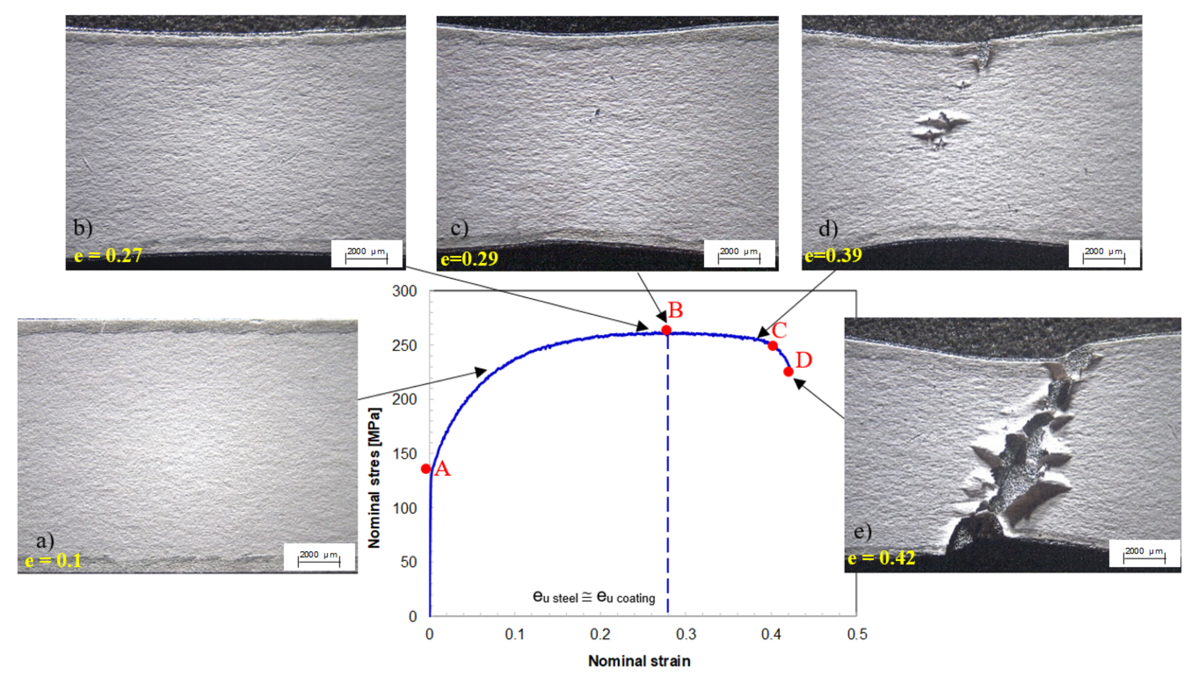
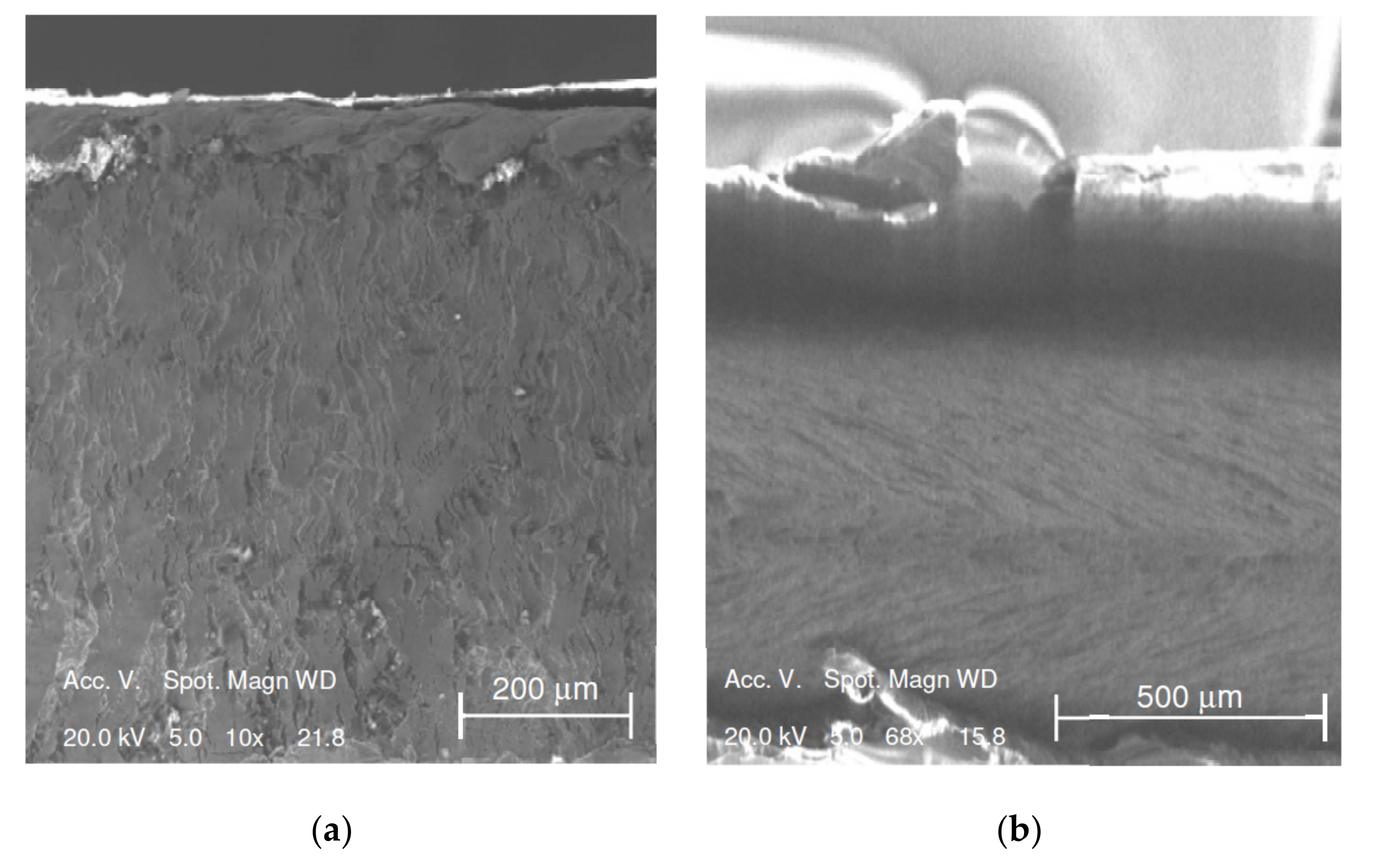
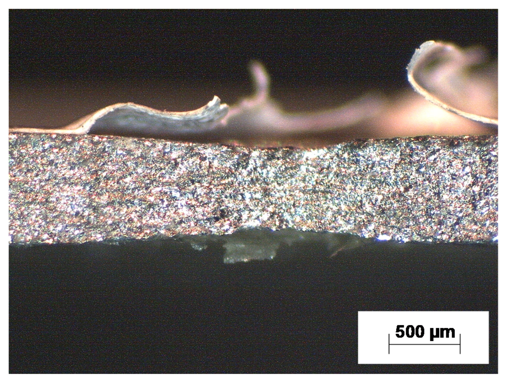
    • In the region of uniform elongation of the steel sheet, the paint coating does not exhibit any superficial damage, even though an orange-peel finish appears. At the onset of necking, damages take place and become larger with increasing strain;
    • In the uniform deformation region, thicknesses of both steel sheet and paint coating layers are almost constant along the gage length of the sample, while in the post-necking region, a marked decrease in thickness is observed in the zone where necking occurs;
  • Biaxial balanced stretching condition:
    • The forming limit of the pre-painted steel sheet is defined by the occurrence of coating film damages since the limiting dome height of coating is lower than the one of the steel sheet;
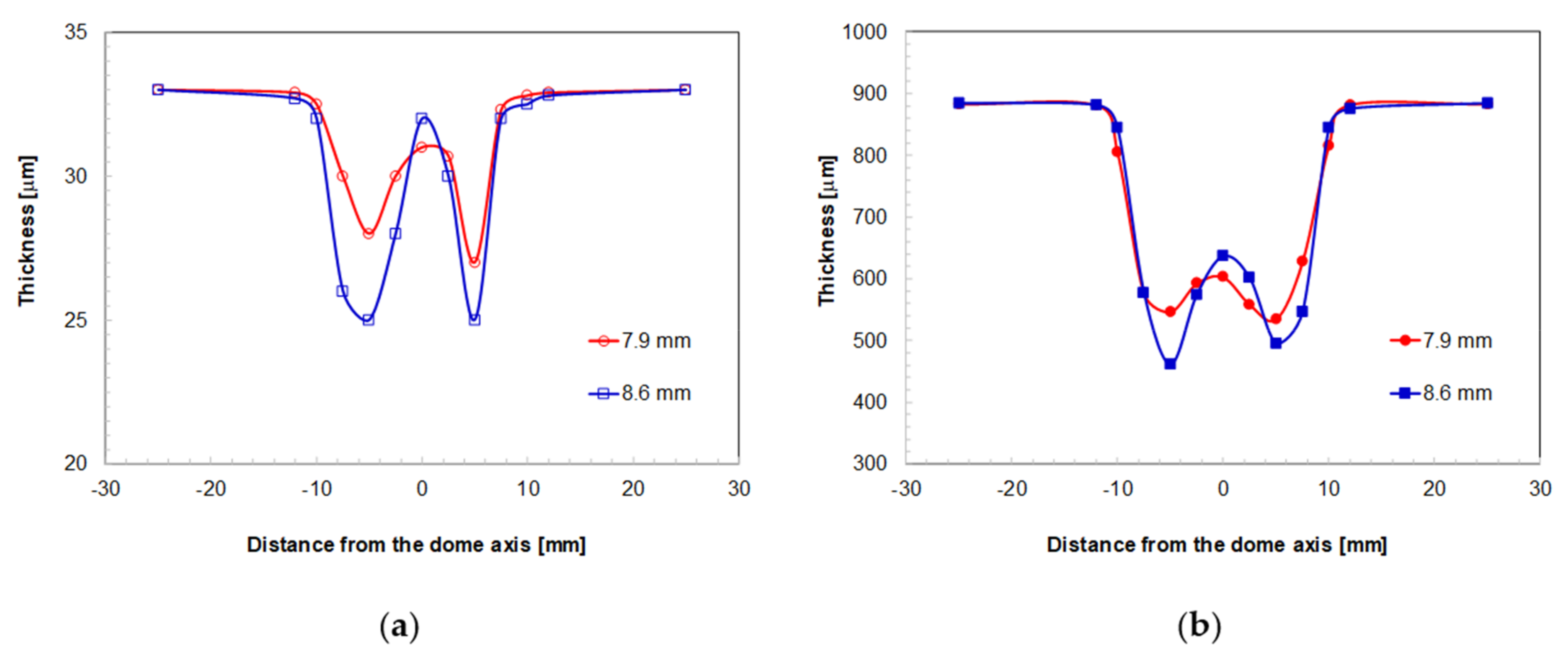
    • A negligible thickness variation in the flange zone and a marked thinning from the die edge to the dome axis can be observed. For each layer, the lowest thickness occurs at a radial distance from the dome axis of about 5 mm.
The degree of damage to the paint coating depends on the different loading conditions; under the uniaxial tensile stress state, the paint coating is able to follow the metal sheet during deformation until the onset of necking, while it exhibits superficial aesthetic damages before fracture of the metal sheet under the biaxial balanced stretching condition.
Finally, in the zones subjected to the biaxial balanced stretching condition, the paint coating thickness is defined by the highest thinning value into the deformed part. Hence, a coating over-thickness must be accepted in the other areas of the sheet characterized by lower thinning, with a material waste and an increase in costs. In the regions subjected to uniaxial stretching, this problem can be neglected since thickness keeps almost uniform.

Author Contributions

Conceptualization, A.F. and M.S.; Data curation, T.M. and M.S.; Formal analysis, A.F., T.M. and M.S.; Investigation, T.M. and M.S.; Project administration, A.F.; Supervision, A.F.; Writing—Original draft, M.S.; Writing—Review and editing, A.F. All authors have read and agreed to the published version of the manuscript.

Funding

This research received no external funding.

Acknowledgments

Massimiliano Pieralisi, Luciano Greco, and Daniele Ciccarelli are acknowledged for their contributions in carrying out the experimental tests.

Conflicts of Interest

The authors declare no conflict of interest.

References

  1. Kubo, Y.; Hanya, K.; Kodama, S. Steel sheet for the better human life (application for household electrical appliances, OA equipment). Nippon Steel Tech. Rep. 2012, 101, 48–56. [Google Scholar]
  2. Vayeda, R.; Wang, J. Adhesion of coatings to sheet metal under plastic deformation. Int. J. Adhes. Adhes. 2007, 27, 480–492. [Google Scholar] [CrossRef]
  3. Kaczmarczyk, J. Modelling of guillotine cutting of a cold-rolled steel sheet. Materials 2019, 12, 2954. [Google Scholar] [CrossRef] [PubMed] [Green Version]
  4. Escobar-Saldívar, L.J.; Smith, N.R.; González-Velarde, J.L. An approach to product variety management in the painted sheet metal industry. Comput. Ind. Eng. 2008, 54, 474–483. [Google Scholar] [CrossRef]
  5. Lange, J.; Luisier, A.; Schedin, E.; Ekstrand, G.; Hult, A. Development of scratch tests for pre-painted metal sheet and the influence of paint properties on the scratch resistance. J. Mater. Process. Technol. 1998, 86, 300–305. [Google Scholar] [CrossRef]
  6. Prosek, T.; Nazarov, A.; Olivier, M.G.; Vandermiers, C.; Koberg, D.; Thierry, D. The role of stress and topcoat properties in blistering of coil-coated materials. Prog. Org. Coatings 2010, 68, 328–333. [Google Scholar] [CrossRef]
  7. Moon, J.I.; Lee, Y.H.; Kim, H.J. Prediction of formability in drawing of PCM using tensile test and DMA creep test. Polym. Test. 2012, 31, 572–578. [Google Scholar] [CrossRef]
  8. Behrens, B.A.; Gaebel, C.M. Formability of an anti-fingerprint clear coating on satin stainless steel sheet metal. Prod. Eng. 2013, 7, 275–281. [Google Scholar] [CrossRef]
  9. Huang, C.H.; Schmid, S.R.; Wang, J.E. Thermal effects on polymer laminated steel formability in ironing. J. Manuf. Sci. Eng. Trans. ASME 2001, 123, 225–230. [Google Scholar] [CrossRef]
  10. ASTM A653/A653M-19a, Standard Specification for Steel Sheet, Zinc-Coated (Galvanized) or Zinc-Iron Alloy-Coated (Galvannealed) by the Hot-Dip Process; ASTM International: West Conshohocken, PA, USA, 2019.
  11. EN 10346:2015, Continuously Hot-Dip Coated Steel Flat Products for Cold Forming—Technical Delivery Conditions; ASTM International: West Conshohocken, PA, USA, 2015.
  12. EN 10143:2006, Continuously Hot-Dip Coated Steel Sheet and Strip—Tolerances on Dimensions and Shape; ASTM International: West Conshohocken, PA, USA, 2006.
  13. International, A. ASTM E8/E8M-16a, Standard Test Methods for Tension Testing of Metallic Materials; ASTM International: West Conshohocken, PA, USA, 2016.
  14. International, A. ASTM E646-16, Standard Test Method for Tensile Strain-Hardening Exponents (n -Values) of Metallic Sheet Materials; ASTM International: West Conshohocken, PA, USA, 2016.
  15. Kalpakjian, S.; Schmid, S.R. Manufacturing Engineering & Technology, 8th ed.; Pearson Education: London, UK, 2019; ISBN 0135228603. [Google Scholar]
  16. Sasso, M.; Mancini, E.; Chiappini, G.; Simoncini, M.; Forcellese, A. Adapted Nakazima test to evaluate dynamic effect on strain distribution and dome height in balanced biaxial stretching condition. Int. J. Mech. Sci. 2018, 148, 50–63. [Google Scholar] [CrossRef]
  17. Forcellese, A.; Simoncini, M. Plastic flow behaviour and formability of friction stir welded joints in AZ31 thin sheets obtained using the “pinless” tool configuration. Mater. Des. 2012, 36, 123–129. [Google Scholar] [CrossRef]
  18. Bruni, C.; Forcellese, A.; Gabrielli, F.; Simoncini, M. Post-welding formability of AZ31 magnesium alloy. Mater. Des. 2011, 32, 2988–2991. [Google Scholar] [CrossRef]
  19. Forcellese, A.; Fratini, L.; Gabrielli, F.; Simoncini, M. Formability of Friction Stir Welded AZ31 Magnesium Alloy Sheets; Trans Tech Publications: Stafa-Zurich, Switzerland, 2010; Volume 638–642, ISBN 0878492941. [Google Scholar]
  20. Casalino, G.; El Mehtedi, M.; Forcellese, A.; Simoncini, M. Effect of cold rolling on the mechanical properties and formability of FSWed sheets in AA5754-H114. Metals 2018, 8, 223. [Google Scholar] [CrossRef] [Green Version]
  21. American Society for Metals. Metals Handbook: Forming and Forging (Volume 14), 9th ed.; ASM International: Novelty, OH, USA, 1980; ISBN 0871700204. [Google Scholar]
  22. Kim, H.Y.; Hwang, B.C.; Bae, W.B. An experimental study on forming characteristics of pre-coated sheet metals. J. Mater. Process. Technol. 2002, 120, 290–295. [Google Scholar] [CrossRef]
Figure 1. Scheme of a pre-painted steel sheet.
Metals 10 00053 g001
Figure 2. Cross section of the un-deformed pre-painted steel sheet.
Metals 10 00053 g002
Figure 3. Tensile samples in pre-painted steel sheet before and after tests.
Metals 10 00053 g003
Figure 4. Magnification of a damage on the paint coating surface of a deformed tensile sample in pre-painted steel sheet.
Metals 10 00053 g004
Figure 5. Sheet metal and coating thickness evaluation method.
Metals 10 00053 g005
Figure 6. (a) Equipment used for hemispherical punch test; (b) disk-shaped samples in pre-painted steel sheet before and after tests.
Metals 10 00053 g006
Figure 7. (a) Deformed disk-shaped sample cut along the radial cross-section and embedded for the stereomicroscopic analysis, and (b) sheet and coating thickness measurement method.
Metals 10 00053 g007
Figure 8. (a) Nominal stress vs. nominal strain curve, and (b) true stress vs. true strain curve of pre-painted steel sheet.
Metals 10 00053 g008
Figure 9. Painted surface of tension-tested samples at different strain levels: (a) 0.1, (b) 0.27, (c) 0.29, (d) 0.39 and (e) 0.42.
Metals 10 00053 g009
Figure 10. SEM images of: (a) longitudinal section, and (b) fracture surface of tension-tested sample.
Metals 10 00053 g010
Figure 11. Longitudinal section of a tensile sample deformed in the post-necking region obtained by stereomicroscopy.
Metals 10 00053 g011
Figure 12. Effect of strain level on the thickness distribution in the different layers of deformed pre-painted sheet vs. distance from the half length of the tensile sample gage: (a) paint coating and (b) steel sheet (initial thickness values: paint coating, 35 m; steel sheet, 880 m).
Metals 10 00053 g012
Figure 13. Typical punch load vs. punch stroke curve recorded during hemispherical punch test of the pre-painted steel sheet.
Metals 10 00053 g013
Figure 14. Painted surface of the disk-shaped samples deformed by the hemispherical punch test, at different punch stroke values: (a) 5 mm, (b) 8.1 mm, (c) 9 mm, (d) 9.8 mm and (e) 10.1 mm.
Metals 10 00053 g014
Figure 15. SEM image at high magnification of the paint coating–sheet interface of the disk-shaped sample deformed at a punch stroke equal 8.1 mm.
Metals 10 00053 g015
Figure 16. (a) Radial cross section of the deformed pre-painted sample obtained by merging different images at the same magnification: (b) and (c) are high magnifications of the paint coating failure (punch stroke equal to 8.6 mm).
Metals 10 00053 g016
Figure 17. (a) Radial cross section of the deformed pre-painted sample obtained by merging different images at the same magnification: (b) and (c) are high magnifications of the paint coating failure (punch stroke equal to 7.9 mm).
Metals 10 00053 g017
Figure 18. Effect of punch stroke on the thickness distribution in the different layers of deformed pre-painted disk-shaped sample vs. distance from the dome: (a) paint coating and (b) steel sheet layers (initial thickness values: paint coating, 35 μm; steel sheet, 880 μm).
Metals 10 00053 g018
Table 1. Mechanical parameters of pre-painted steel sheet evaluated by uniaxial tensile tests.
Strength Coefficient, K
[MPa]
Strain Hardening Exponent, nYield Strength, YS
[MPa]
Ultimate Tensile Strength, UTS
[MPa]
Uniform Elongation, euTotal Elongation, etNormal Anisotropy, R
4890.271422600.290.422.2

