Article

Influence of Ultrasound on Pore and Crack Formation in Laser Beam Welding of Nickel-Base Alloy Round Bars

1
Laser Zentrum Hannover e.V., Hollerithallee 8, 30419 Hannover, Germany
2
Institute of Dynamics and Vibration Research, Leibniz University Hannover, An der Universität 1, 30823 Garbsen, Germany
*
Author to whom correspondence should be addressed.
Metals 2020, 10(10), 1299; https://doi.org/10.3390/met10101299
Submission received: 31 August 2020 / Revised: 16 September 2020 / Accepted: 25 September 2020 / Published: 29 September 2020
(This article belongs to the Special Issue Hybrid Bulk Metal Components)

Abstract

:
Welding by laser beam is a method for creating deep and narrow welds with low influence on the surrounding material. Nevertheless, the microstructure and mechanical properties change, and highly alloyed materials are prone to segregation. A new promising approach for minimizing segregation and its effects like hot cracks is introducing ultrasonic excitation into the specimen. The following investigations are about the effects of different ultrasonic amplitudes (2/4/6 µm) and different positions of the weld pool in the resonant vibration distribution (antinode, centered, and node position) for bead on plate welds on 2.4856 nickel alloy round bars (30 mm diameter) with a laser beam power of 6 kW. The weld is evaluated by visual inspection and metallographic cross sections. The experiments reveal specific mechanisms of interaction between melt and different positions regarding to the vibration shape, which influence weld shape, microstructure, segregation, cracks and pores. Welding with ultrasonic excitation in antinode position improves the welding results.

1. Introduction

Nickel alloys with an addition of about 20% chromium show high corrosion resistance and high strength at elevated temperatures, so they are commonly used for high-temperature applications and in corrosive environments, as example for fan blades in turbines or for parts in chemical plants [1]. There are several trade names for this material group like Inconel, Chronin or Nicrofer.
Welding of highly alloyed nickel leads to similar problems as in welding stainless steel. Segregation is likely to occur due to a high amount of alloying elements. Those can form lately solidifying phases between the primary grains, and effect hot cracking [1]. In addition, segregated alloying elements are missing in the residual material, which changes its properties like corrosion resistance in the case of chromium [2].
Ultrasonic excitation of solidifying melt leads to mixing of the melt [1]. Hence, it can prevent segregation including its consequences and foster a finer grain structure, because dendrites break through mixing, which in turn creates more nucleation sites [3]. A finer grain structure improves strength as well as ductility and hardness [4]. In addition, porosity and hardness in the heat affected zone can be decreased and penetration depth can be increased for aluminium welds [5,6]. Another effect of ultrasonic excitation at high amplitudes is acoustic cavitation, which occurs in fluids and can be divided into gas bubble cavitation and vapour bubble cavitation. In vapour bubble cavitation the fluid turns to gas when its pressure becomes low enough. This gas bubble implodes immediately, when the pressure rises sufficiently high for condensation. In result, liquid is drawn into the generated vacuum and a pressure shock of around 1010 Pa with temperatures of about 10,000 K occurs [7]. Close to solid interfaces a liquid micro jet, coursed by an imploded bubble, generates a stress peak on the interface and may lead to damage. In ultrasonically assisted welding, cavitation may happen in the melt pool and for a stationary wave cavitation is unlikely to occur in a melt pool at nodal position. Gas bubble cavitation occurs when gas is present in a liquid. The gas itself can form bigger bubbles when the pressure changes periodically by ultrasonic excitation or the bubbles can grow at the surface of particles. Such big bubbles slowly rise up by buoyancy, even if they shrink slightly when the ultrasonic pressure increases again. In ultrasonic laser beam welding the keyhole interaction with cavitation effect has to be examined [7].
The melt dynamics are also influenced by ultrasonic excitation due to the effect of acoustic streaming. Besides an induced oscillating motion, a time-dependent unidirectional flow can be induced [8], which suggests the possibility of effecting asymmetrical welds. Wu [8] gave a mathematical overview of how a fluid flow can be generated by ultrasound. He assumed that the flow force in a standing wave originates at the wave antinode. If the molten pool lies in this position, it is loaded equally, resulting in a symmetrical seam. The same applies if the molten pool is located in the wave node. Due to the same distance to the left and right wave antinode, cf. Figure 1, a symmetrical influence is also created. If, however, welding is carried out in an intermediate position, the distance to one wave antinode is smaller than to the other wave antinode. Wang et al. [9] investigated the influence of acoustic streaming on the solidification process of an Al2Cu alloy. They describe that the force Fn emanating from acoustic streaming depends, among other things, on the distance to the antinode. It leads to the assumption that the asymmetrical weld seam is a result of the force difference due to the unequal distances which causes a material flow to one side.
Porosity can be influenced by the melt solidifaction morphology: Exogenous solidification originates from the melt border with growing columnar crystals and endogenous solidification happens in the melt volume with growing equiaxed crystals. At high supercooling of exogenous solidification also equiaxed crystals form in the melt volume. Equiaxed crystals can as well be promoted by small particles for heterogeneous nucleation. Gas bubbles can move through a mushy melt with equiaxially solidifying crystals, but in a columnar dendrite network they are trapped [10].
Ultrasonic excitation was applied in many cases only for welding steel and aluminium alloys. Zhou et al. [1] conducted pulsed laser welding with ultrasonic excitation on dissimilar welds of nickel-based Hastelloy C-276 with austenite stainless steel 304 in overlap configuration. No grain refinement occurred, but segregation was strongly reduced.
In previous simulations [11] and experiments on stainless steel and aluminium alloy suitable ultrasonic frequency range and vibration amplitudes were found, which will be tested on a nickel alloy. The effect of antinodal ultrasonic excitation on a liquid pool surrounded by solid material at its sides and air at its top was investigated. The liquid is pushed up at the solid wall sides and can be ejected at very high excitation levels. In result, a V-shaped weld seam collapse forms [11]. Experiments with similar setups showed that with laser beam welding sagging appears in the weld and the keyhole’s bottom part can be closed by ultrasonic excitation [4,12]. The experiments in our contribution investigate the ultrasonic excitation effects on partial penetration laser welded nickel alloy round bars, see Table 1, to improve the weld properties and minimize pore and crack formation. The welds will be evaluated by visual inspection and metallographic cross sections.

2. Experimental Setup

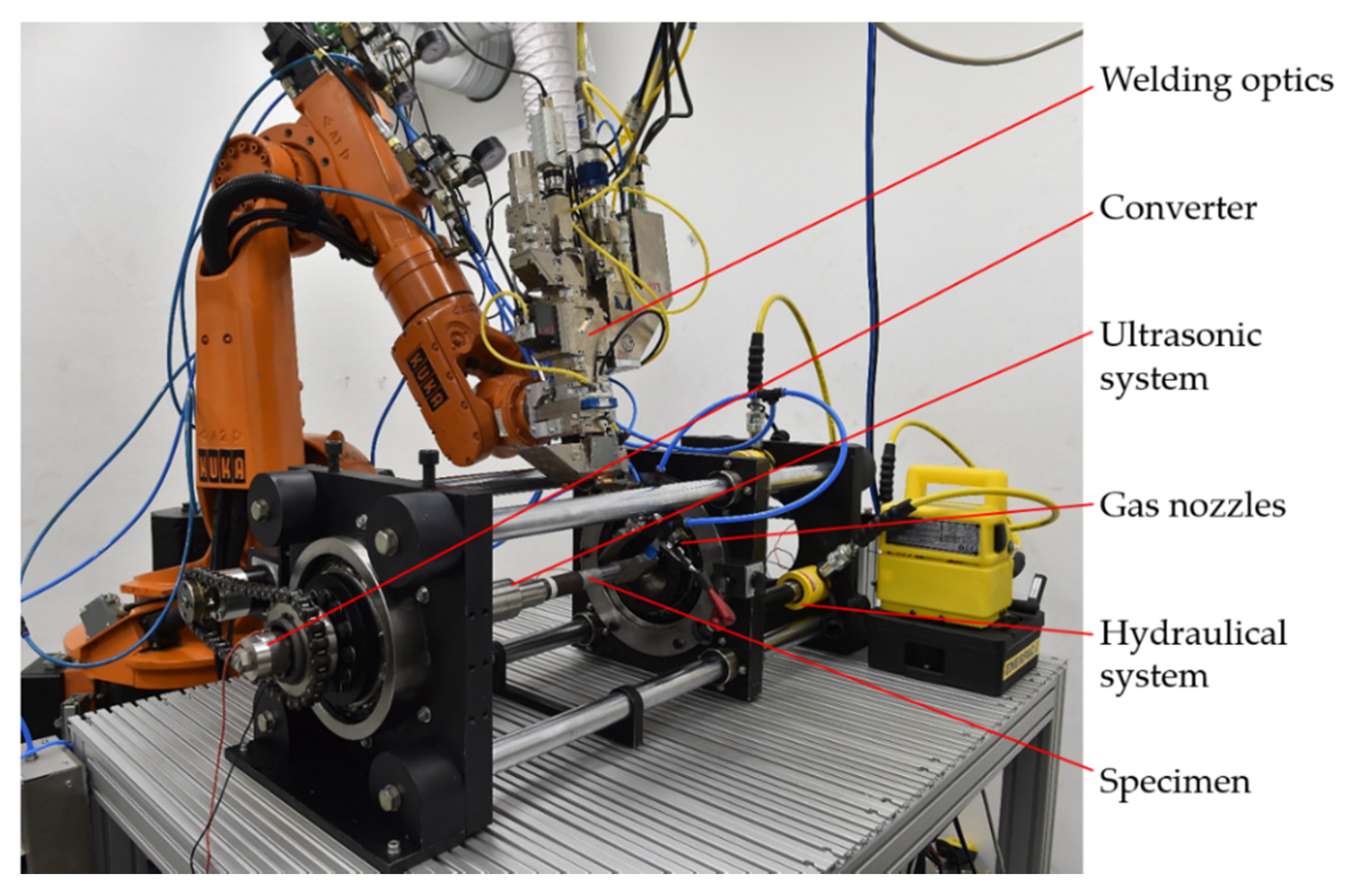
2.1. Laser Beam Welding Setup

For the welding tests, a diode-pumped solid state disk laser system (TruDisk 16002, Trumpf, Ditzingen, Germany) was used with specifications according to Table 2.
The laser head is held in one single position by a robot system (Kuka, Augsburg, Germany) and the welding speed is provided by rotating the specimen for the ultrasonic assisted laser beam welding process, see Figure 2. The complete setup is described in detail in [11]. Only adapters and specimens have been changed.

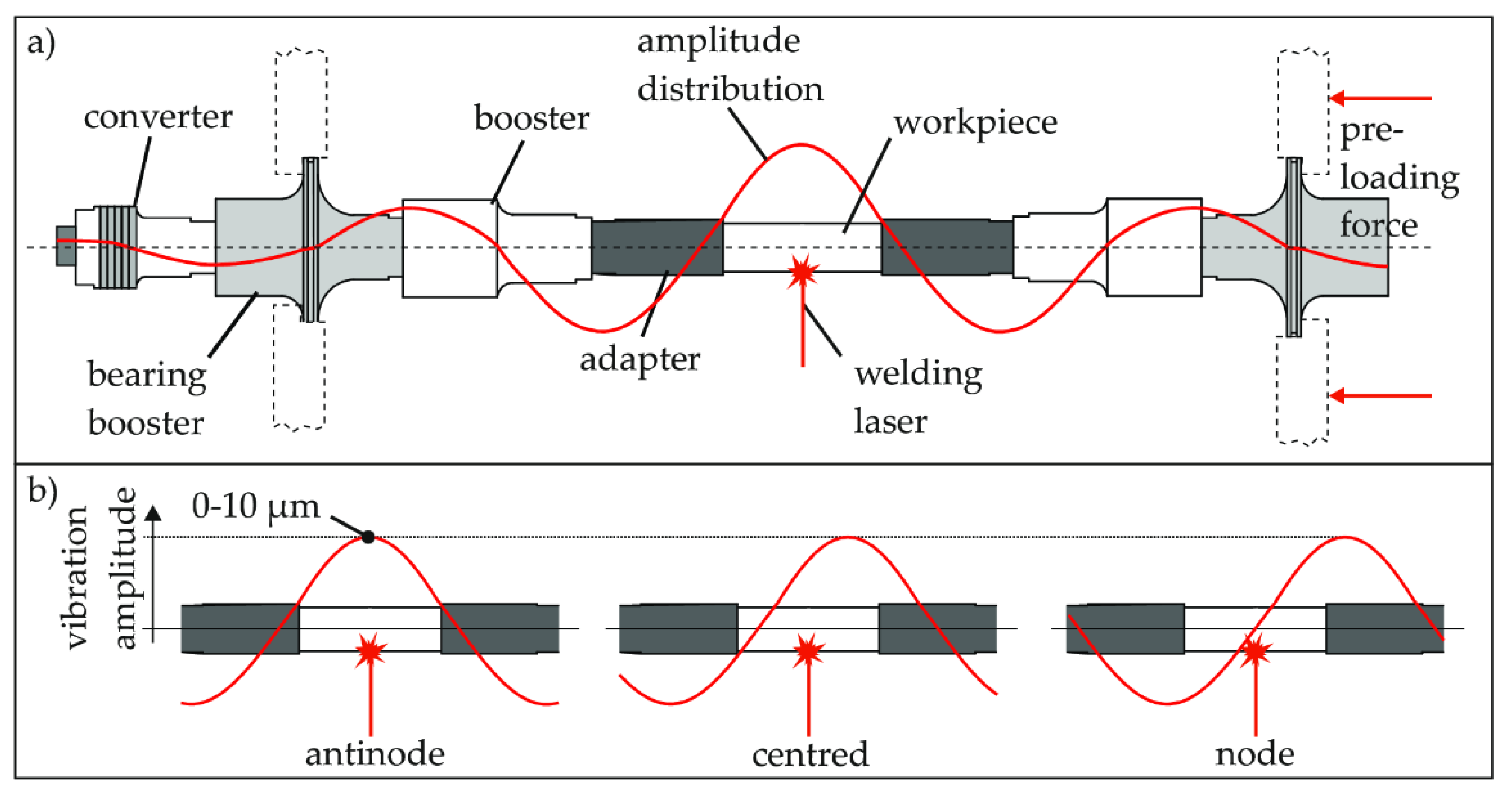
2.2. Ultrasonic System

The specimens, as part of the ultrasonic system, are excited to resonant longitudinal oscillations in the ultrasonic range during the welding process. For this purpose, the specimens are pre-stressed in the ultrasonic system between two adapters, see Figure 3a. Beside the specimens the system consist of adapters as well as boosters and bearing boosters both amplifying the vibration amplitude of the ultrasonic transducer up to the joining point. The vibration amplitude is adjusted between 0 µm and 10 µm in the antinode (closest one to the weld), depending on the current amplitude set. Since at resonance the current amplitude is proportional to the vibration amplitude. The ultrasonic transducer (built by IDS, Institute of Dynamics and Vibration Research, Garbsen, Germany) is driven in the systems resonance frequency (7. Longitudinal mode) at approximately 20 kHz. The control of the phase between current and voltage of the transducer guaranties the stable operation at resonance as well as the control of the current amplitude keeps the vibration amplitude, at the closest anti-node to the weld, steady. Both is carried out utilizing a control unit, the DPC 500/100 [14]. With different adapters, the joint can be placed at any point of the amplitude distribution. Three significant positions are defined for the investigations. In the antinode position, the vibration amplitude has the highest value, see Figure 3b, (this value is always used to describe the amplitude) and the mechanical stress amplitude is minimal. If the joint is placed within the node position, the vibration amplitude becomes zero and the mechanical stress amplitude has its local maximum. In addition, the joint is placed exactly between the antinode and the node of the wave in the centered position. Both vibration amplitude and mechanical stress have significant amplitudes here. The system is preloaded hydraulically. This preloading force is selected to be high enough, that the components cannot clatter during the excited longitudinal vibration. It is selected to be 120 kN, based on a specimen diameter of 30 mm.

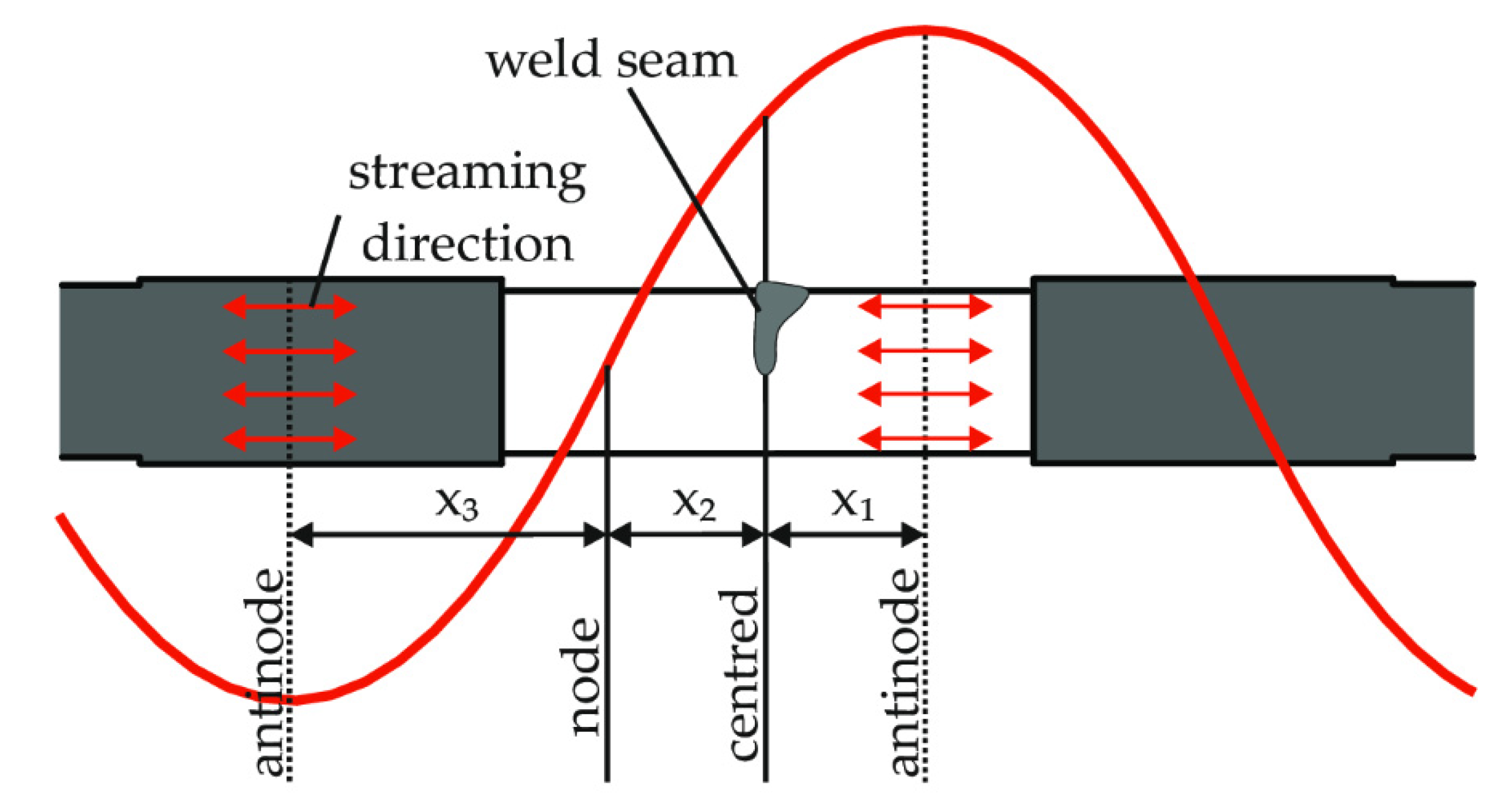
3. Experimental Procedure

The specimen are round bars with a diameter of 30 mm and length of 30 mm made of the nickel alloy 2.4856. Those are used for all bead on plate welds. For joining, the optics are angled by 20°. The laser focus point is adjusted to be 4 mm in the sample and 6 mm backwards over the specimen’s surface from the angular point. This orientation of the laser spot avoids the formation of melt drops on the specimen’s surface resulting from the weight of the melt while rotating the round bars. A laser beam power of 6 kW and a welding speed of 1.00 m/min are used. The focal lense (welding optics: BEO D70, Trumpf, Ditzingen, Germany) is protected by a crossjet and two flat nozzles provide argon as shielding gas with a pressure of 6 bar and a flow rate of 60 L/min at an angle of 45°. The flat nozzles are positioned with 50 mm distance to each other and to the specimen. One nozzle is aiming at the specimen bottom and the other one is aiming above the specimen. According to the test plan (see Table 3), for an ultrasonic amplitude of 6 µm only one welding test per wave position is conducted for testing the effects of excessive excitation, which effects spatter. The applied parameters were determined by previous experiments [4,12].
Metallographic cross sections of each specimen are prepared. The etching is conducted with Adler’s etchant until the microstructure appears. The weld width, weld depth, weld metal area and pore area are identified and evaluated. In addition, scanning electron microscopy (SEM)-investigations including energy dispersive X-ray spectroscopy (EDX)-analysis (Seifert ISOVOLT 320, 80 kV, 20 mA, 3.6 min, Rich. Seifert & Co., Ahrensburg, Germany) are used for analyzing cracks and chemical composition.

4. Experimental Results

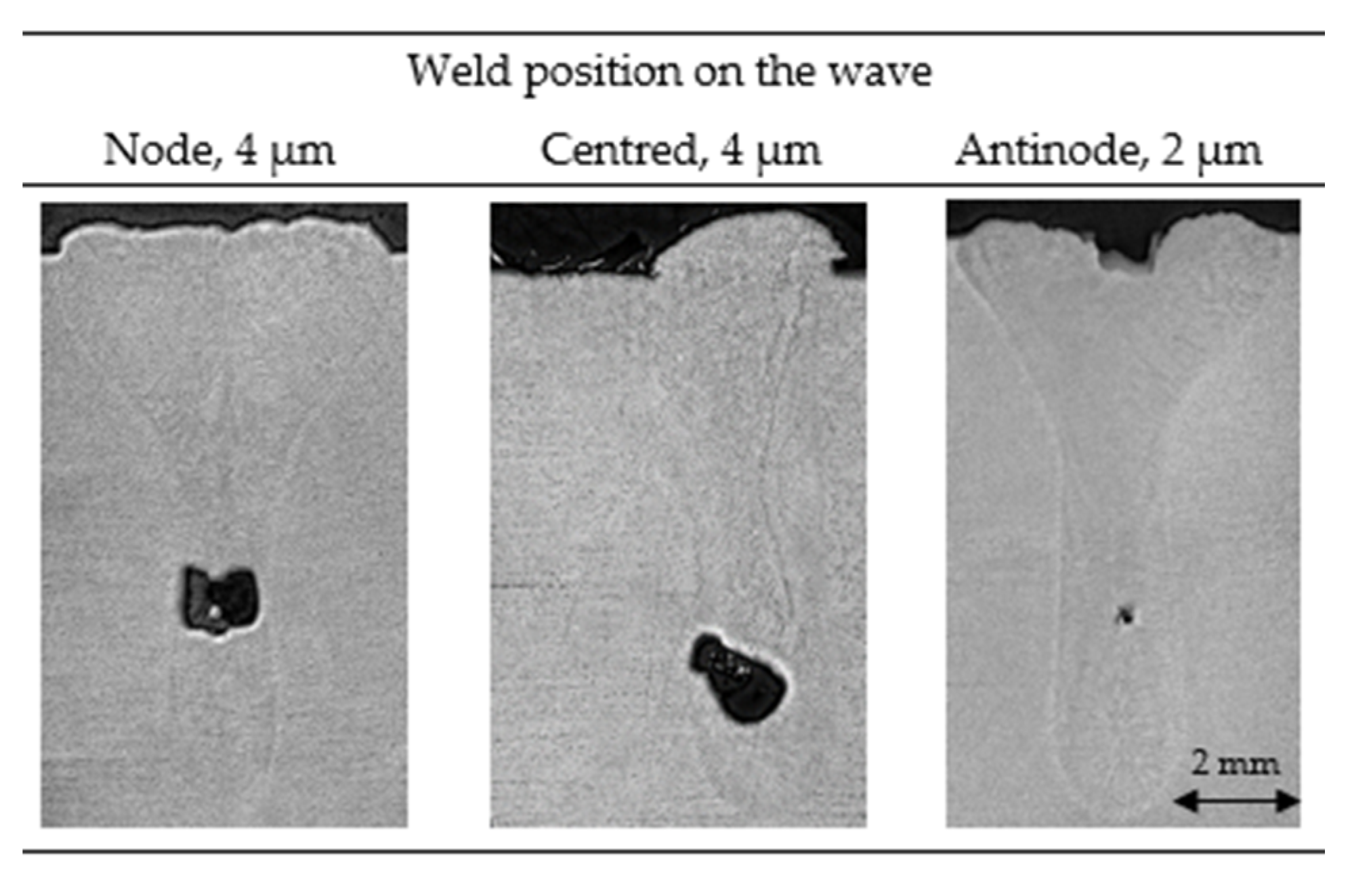
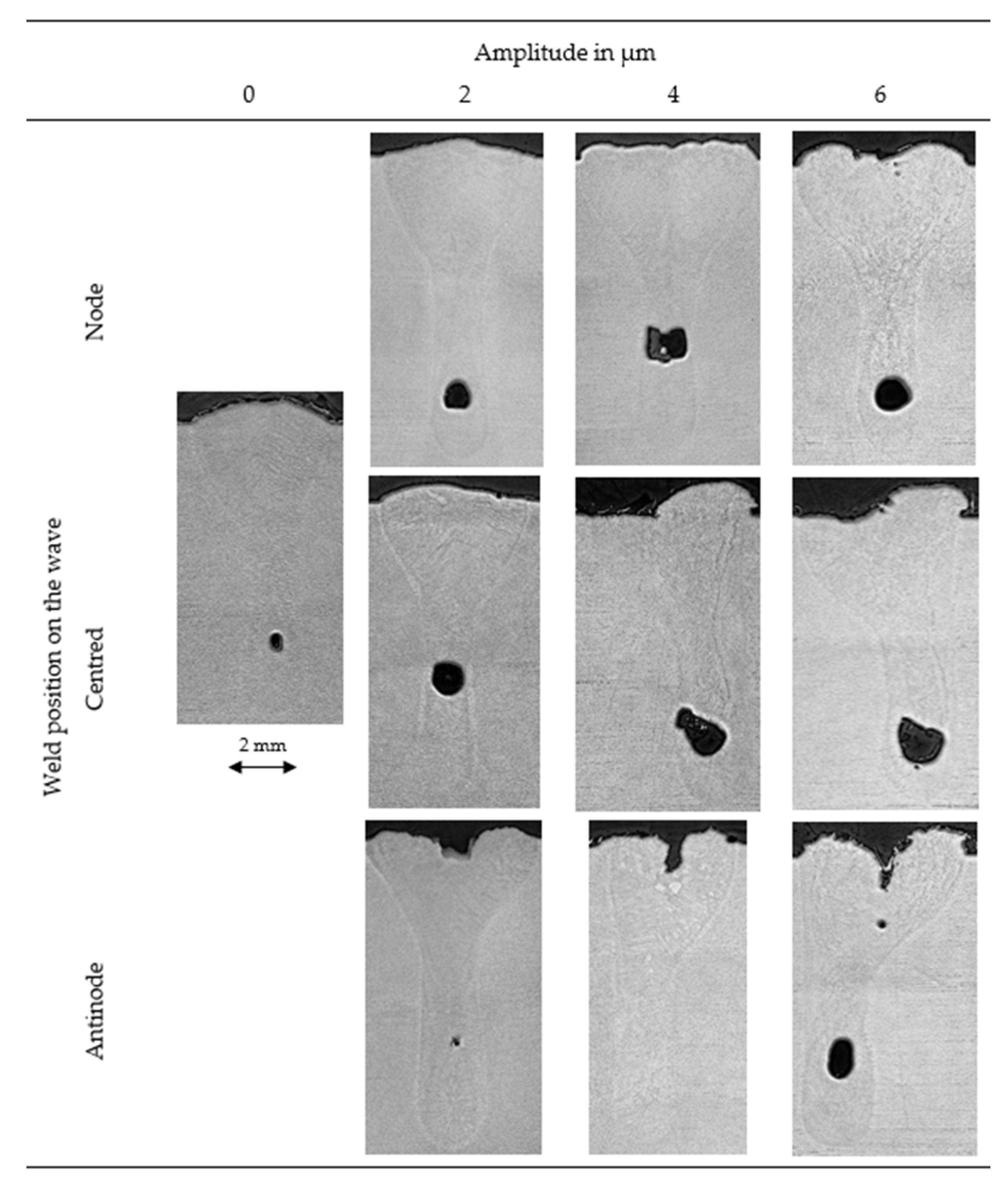
4.1. Weld Appearance
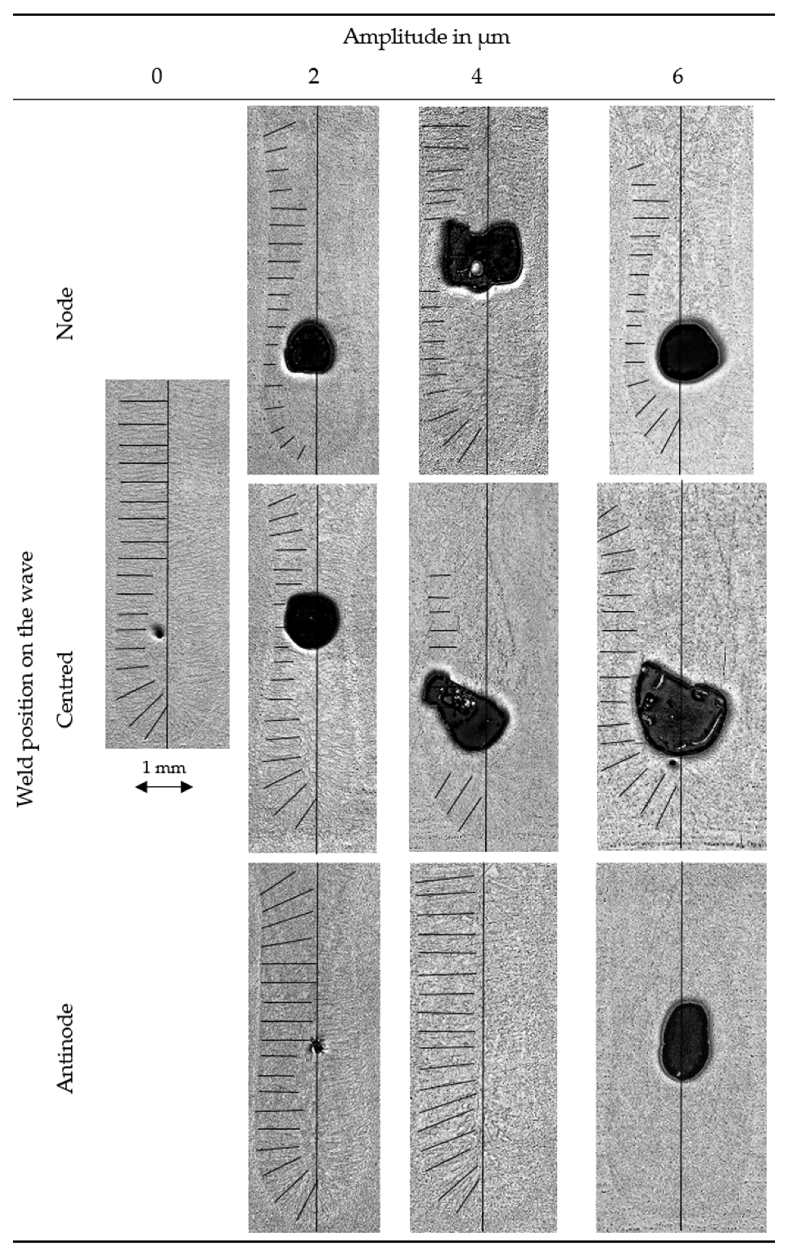
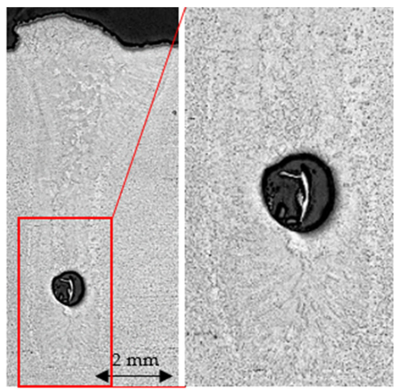
The outer appearance of weld seams in the nickel alloy 2.4856 (see Figure 4), depends strongly on position according to both the vibration distribution and vibration amplitude. With ultrasonic excitation and weld in node position the weld surface becomes wavy starting with an amplitude of 4 µm.
For the weld in the centred position the ultrasound leads to an unsymmetrical material distribution. This effect increases with increasing amplitudes. In addition, sagging appears starting with 4 µm amplitude. For the weld in antinode position sagging appears with ultrasound. At an amplitude of 4 µm the sagging becomes narrower and the edges touching each other partially. At an amplitude of 6 µm strong spatter occur additionally where the edges touch each other. This shows the melt pool dynamics similar to our simulation in [11].
Evaluating the specimens’ cross-sections, see Figure 5, reveals more effects due to the ultrasonic excitation. Pores appear mostly in the weld root area. The weld seam without ultrasonic excitation has one small pore in the root area with a diameter of about 0.5 mm. For the welds in the nodal position, the pores increase up to a diameter of 1.3 mm and the weld surface becomes wavier. For the weld in centred position at an amplitude of 2 µm a big pore with a diameter of about 1.0 mm is located in the root area and the upper weld area is not symmetrical anymore. At amplitudes of 4 µm and 6 µm big pores with a diameter of about 1.4 mm appear and the weld symmetry decreases further until one weld side is straight from the specimen surface to its root. On this side, a reinforcement appears on the specimen surface. In the antinode position, sagging appears in the middle of the weld surface. The welds with amplitudes of 2 µm and 4 µm show show no or little pores with a diameter of about 0.2 mm in the root area, whereas an amplitude of 6 µm shows a big pore with a diameter of about 1.0 mm in the root and a little pore in the upper area. The weld shapes in centred and antinode position are similar for amplitudes of 4 µm and higher, although symmetrical conditions are expected for antinode position.
It is important to consider the laser spot position on the weld seam. On those specimens where ultrasound was applied and asymmetric welds and sagging has been found, the laser spot aims onto one edge of the welding seam. Also considering the cross sections, it becomes clear that the laser beam still creates a keyhole, which penetrates the specimen rectangular to its surface, but the upper weld area shifts towards one side. The reason is likely a directed melt flow, which removes solid metal from one side. The directed melt flow may result from changed weld pool dynamics by acoustic streaming [8,9]. Another reason for asymmetric welds could be the dynamics of the weld during the oscillation, what is simulated in [11]. Effects such as non-parallel interfaces, caused by the V-shape of the melt, between the melt pool and the environment can promote the ejection of the melt towards one side. In order to validate the influence of acoustic streaming on the weld seam, further test series are planned for the future. Special attention will be paid to the ultrasonic amplitude distribution directly at the weld pool in order to investigate the additional influence on the weld shape due to the different coupling between solid and viscous liquid material.

4.2. Pore Formation

The pore areas in Figure 5 show large differences. Without ultrasonic excitation the pore area is low, with diameters of about 0.5 mm. Welds at the centred and nodal positions have similar sized pore areas with diameters of about 1.3 µm at all ultrasonic amplitudes. In contrast, welds at antinode position have very small pore areas with diameters of about 0.2 mm at an amplitude of 2 µm and no pores at an amplitude of 4 µm. However, at an amplitude of 6 µm the pore area increases strongly to a diameter of about 1.0 mm. Commonly pores appear in the middle or bottom weld area, see Figure 5. In general, the pores have round shapes, because they contain gas. This gas can be residual keyhole-gas. Pore formation is modified by an ultrasonically modified melt flow. According to [11], welding at antinode position can course an ejection of melt and a V-shaped opening of the melt due to the strong dynamics. The opening supports the keyhole and promotes gas escapement from the melt. In contrast, during welding at the centred position the melt is moved to one single direction, as described in Section 4.1, crossing and disturbing the keyhole, which effects turbulences. Hence, the melt absorbs keyhole-gas resulting in many times bigger pores. Welding at nodal position neither foster a V-shaped weld seam collapse nor turbulences, but increases the pore area due to compressing the melt, which either closes the keyhole’s middle part before the bottom keyhole gas can escape or promotes combining of gas bubbles and holding the gas in the metal resulting in pores. Acoustic cavitation could as well influence this process by inducing growth and shrinkage, which promotes bubble merging. Welds at nodal and centred position show similar pore areas, which can mean that the keyhole is disturbed only little and that acoustic cavitation has a big influence on increasing pores by merging little pores. Another possibility is that keyhole-disturbance and node-effects are of similar influence. For welds at antinode position there should be an optimal vibration amplitude depending on the welding speed to support the keyhole with no keyhole-disturbance by flow direction. At an amplitude of 6 µm big pores form due to a previously described strong melt flow directing mechanism for welds at antinode position.
The porosity shape changes with the position on the wave, see Figure 6. In the weld at nodal position at an amplitude of 4 µm a slightly rectangular-, compressed and collapsed-looking pores has been found due to node position compression. In the centred positioned weld with an amplitude of 4 µm elongated asymmetric pores are found due to the directed melt flow in centred position. At antinode position, the pores are rounder and smaller.
For further investigation of pore formation, the amount of equiaxed microstructure is evaluated visually regarding very low and high amount, see Figure 7. Without ultrasonic excitation there is a very low amount of equiaxed microstructure. With ultrasonic excitation the equiaxed microstructural amount is high for the welds at node and centred position In the micrographs of the welds at antinode position, the equiaxed microstructural amount is very low until an amplitude of 4 µm and becomes high with an amplitude of 6 µm.
The comparison between pore area and equiaxed microstructural amount, see Figure 6 and Figure 7, reveals a relation. Equiaxially solidifying melt promotes mobility, combining and growing of gas bubbles. Therefore, gas bubbles are located in the equiaxed crystal core zone in the middle of the weld, see Figure 8.
Following mechanisms contribute to an equiaxial microstructure. For welds in centred position the induced melt flow crushes dendrites, which promotes heterogeneous nucleation. For welds at nodal position dendrites are crushed by nodal pressure, which again promotes heterogeneous nucleation. For welds at antinode position with amplitudes below 6 µm equiaxial solidification is reduced to a similar amount as without excitation because no dendrites are crushed and hence no heterogeneous nucleation is fostered. At an amplitude of 6 µm the equiaxed amount rises due to strongly enhanced directed melt flow, which crushes dendrites and supports heterogeneous nucleation. Additionally, welding at antinode position eliminates porosity by promoting the absorption of gas into the keyhole by the previously described V-shaped weld seam collapse.

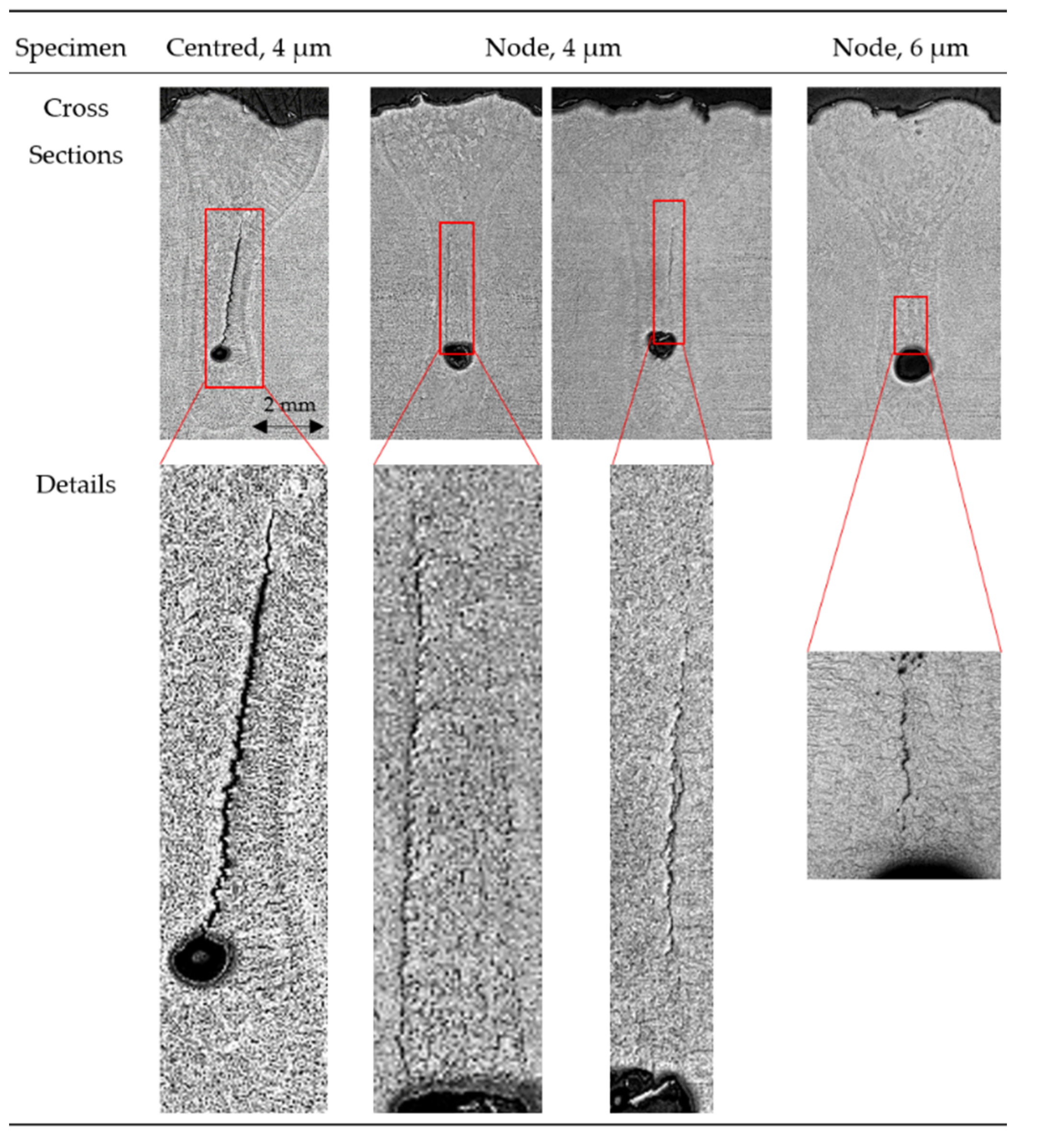
4.3. Crack Formation

Cracks appear in some specimens with welds in centred and nodal position beginning with amplitudes of 4 µm, see Figure 9. The cracks appear around the grain boundaries, which indicates, that those are hot cracks. They appear in the porosity containing equiaxed crystal core zone in the middle of the weld, because they originate from the segregation of alloying elements, which are mainly pushed ahead by the columnar crystal solidification front. As the equiaxed crystal core zone solidifies endogenously most segregated elements remain at the columnar-equiaxed interface and initiate hot cracks.
Cracking does not happen in welds in antinode position, because the amount of equiaxed microstructure is not increased for amplitude lower or equal than 4 µm. The low number of specimens including cracks does only allow assumptions, but cracks in welds in nodal position appear finer than those in welds in centred position and in general cracks become finer with increasing amplitude, because the melt is pressed together periodically and the segregations are pressed between the solidifying phases. With increasing amplitude at the antinode there is an increasing pressure at the node and the segregations are distributed over larger areas. In result, extremely fine cracks or detachments form, which result in severely weakened welds.
Scanning electron microscope (SEM)-investigations, see Figure 10, validate the hot crack assumption, since the grains are intact without sharp edges and the crack surfaces are coated by segregated melt. Energy dispersive X-ray spectroscopy (EDX)-analysis show only small differences in the chemical compositions of weld metal and crack surface because of the small segregation layer thickness. The niobium- and tantalum-contents increase at the crack surface from about 4 wt.% to 7 wt.% for niobium and from about 2 wt.% to 4 wt.% for tantalum; the nickel-content decreases from about 60 wt.% to 55 wt.%.

5. Conclusions

The different welding positions (regarding the vibration distribution) show remarkably different effects compared to samples without ultrasonic excitation, see Table 4. No clear cavitation effects were observed, but cavitation may support the porosity-related effects. In terms of the few incidents of crack formation, segregation is subordinated to the change of microstructure caused by nodal and centred position.
For welds in nodal position the melt underlies pressure, which crushes the dendrites and effects a fine microstructure. Still a small area at the weld margin solidifies columnar and alloying elements segregate at the columnar-equiaxial interface, which can result in hot cracks. Pores form due to enhanced gas mobility in the equiaxially solidifying melt area.
In welds at centred position cracks and pores form due to the enhanced equiaxial solidification. It may result from an ultrasonically modified directed melt flow by acoustic streaming. This would crush dendrites and foster equiaxial solidification. In addition, a typical weld shape results, where the top area is shifted towards one side.
For welds at antinode-position a V-shaped weld seam collapse is promoted, cf. [11], which supports the keyhole and therefore gas escapement from the melt. The equiaxial microstructural amount is reduced, because directed melt flow is enhanced only by a small extent, which only reduces supercooling. Concluding, in antinode position porosity is eliminated and neither segregations nor hot cracks are formed.
Ultrasonic excitation in antinode position appears to be the most suitable excitation option for the welding of 2.4856 nickel-base alloy round bars due to the absence of cracks and due to the suppression of pore formation. It correlates with sagging on the welded round bar’s surface. To avoid sagging, positions close to antinode position with suitable keyhole-support and without sagging as well as pores and cracks should be investigated.

6. Outlook

Pore formation in welds in nodal and centred position probably results from keyhole-disturbance, which will be investigated by optical coherence tomography subsequently. For exact conclusions regarding porosity distribution scanning acoustic microscopy will be used in future and for statistical coverage more experiments have to be conducted.
The temperature distribution over the specimen and the whole ultrasonic system will be investigated because ultrasonic excitation brings in much heat depending on the position in the amplitude distribution. This affects solidification.
As mentioned in Section 5, welding positions close to the antinode position should be investigated. Welds at centred position shows stronger melt shifting effects than antinode position and no V-collapse effect so that it could be used to segregate the effects of V-collapse including gas escapement through the keyhole in antinode position from the melt shifting effect, which also effects antinode position. Finally, the exact mechanism of flow directing will be investigated by simulations regarding the ultrasonic wave behaviour during passing the weld.

Author Contributions

Conceptualization, J.G., C.N., S.N., J.H., J.T., J.W. and S.K.; methodology, J.G., C.N. and S.N.; software, C.N.; validation, J.G., C.N. and S.N.; formal analysis, J.G., C.N. and S.N.; investigation, J.G., C.N. and S.N.; resources, J.G., C.N. and S.N.; data curation, J.G., C.N. and S.N.; writing—original draft preparation, J.G., C.N. and S.N.; writing—review and editing, J.G., C.N., S.N., J.H., J.T., J.W. and S.K.; visualization, J.G. and C.N.; supervision, J.W. and S.K.; project administration, S.N., J.T. and J.H.; funding acquisition, J.W. and S.K. All authors have read and agreed to the published version of the manuscript.

Funding

Funded by the Deutsche Forschungsgemeinschaft (DFG, German Research Foundation)-CRC 1153, subproject A3–252662854.

Acknowledgments

The authors would like to thank the German Research Foundation (DFG) for the financial and organisational support of this project.

Conflicts of Interest

The authors declare no conflict of interest.

References

  1. Zhou, S.; Ma, G.; Dongjiang, W.; Chai, D.; Lei, M. Ultrasonic vibration assisted laser welding of nickel-based alloy and Austenite stainless steel. J. Manuf. Process. 2018, 31, 759–767. [Google Scholar] [CrossRef]
  2. Lee, H.T.; Wu, J.L. Intergranular corrosion resistance of nickel-based alloy 690 weldments. Corros. Sci. 2010, 52, 1545–1550. [Google Scholar] [CrossRef]
  3. Dommaschk, C.D.; Hübler, J.H. Auswirkungen einer Vibrationsbehandlung auf das Erstarrungs- und Speisungsverhalten von Gusswerkstoffen. Gießerei-Prax. 2003, 12, 505–512. [Google Scholar]
  4. Nothdurft, S.; Ohrdes, H.; Twiefel, J.; Wallaschek, J.; Mildebrath, M.; Maier, H.J.; Hassel, T.; Overmeyer, L.; Kaierle, S. Influence of ultrasonic amplitude and position in the vibration distribution on the microstructure of a laser beam welded aluminum alloy. J. Laser Appl. 2019, 31, 022402. [Google Scholar] [CrossRef]
  5. Krajewski, A.; Włosiński, W.; Chmielewski, T.; Kołodziejczak, P. Ultrasonic-vibration assisted arc-welding of aluminium alloys. Bull. Pol. Acad. Sci. Tech. Sci. 2012, 60, 841–852. [Google Scholar]
  6. Kim, J.S.; Watanabe, T.; Yoshida, Y. Ultrasonic vibration aided laser welding of Al alloys: Improvement of laser welding-quality. J. Laser Appl. 1995, 7, 38–46. [Google Scholar] [CrossRef]
  7. Deutsche Gesellschaft für Akustik, e.V. DEGA-Empfehlung 101: Akustische Wellen und Felder. Available online: https://www.dega-akustik.de/fileadmin/dega-akustik.de/publikationen/DEGA_Empfehlung_101.pdf (accessed on 14 August 2020).
  8. Wu, J. Acoustic Streaming and Its Applications. Fluids 2018, 3, 108. [Google Scholar] [CrossRef] [Green Version]
  9. Wang, G.; Croaker, P.; Dargusch, M.; McGuckin, D.; StJohn, D. Simulation of convective flow and thermal conditions during ultrasonic treatment of an Al-2Cu alloy. Comput. Mater. Sci. 2017, 134, 116–125. [Google Scholar] [CrossRef]
  10. Foundry Lexicon: Gas Blister. Available online: www.giessereilexikon.com/en (accessed on 17 August 2020).
  11. Ohrdes, H.; Nothdurft, S.; Nowroth, C.; Grajczak, J.; Twiefel, J.; Hermsdorf, J.; Kaierle, S.; Wallaschek, J. Influence of ultrasonic vibration amplitude on the weld shape of EN AW-6082 utilizing a new excitation system for laser beam welding. Prod. Eng. Special Issue under review.
  12. Nothdurft, S.; Ohrdes, H.; Twiefel, J.; Wallaschek, J.; Hermsdorf, J.; Overmeyer, L.; Kaierle, S. Investigations on the effect of different ultrasonic amplitudes and positions in the vibration distribution on the microstructure of laser beam welded stainless steel. In High-Power Laser Materials Processing: Applications, Diagnostics, and Systems 2020, IX; International Society for Optics and Photonics: Bellingham, WA, USA, 2020; p. 112730J. [Google Scholar]
  13. VDM Metals. Datenblatt Nr. 4118: VDM Alloy 625. Available online: https://www.vdm-metals.com/fileadmin/userupload/Downloads/DataSheets/DatenblattVDMAlloy625.pdf (accessed on 11 August 2020).
  14. Ille, I.; Twiefel, J. Model-based Feedback Control of an Ultrasonic Transducer for Ultrasonic Assisted Turning Using a Novel Digital Controller. Phys. Procedia 2015, 70, 63–67. [Google Scholar] [CrossRef] [Green Version]
Figure 1. Influence of the wave-position on the weld seam.
Metals 10 01299 g001
Figure 2. Experimental setup for ultrasonic assisted laser beam welding.
Metals 10 01299 g002
Figure 3. Ultrasonic system for laser beam welding of round bars with vibration distribution (a) and selected positions for welding tests (b).
Metals 10 01299 g003
Figure 4. Visual inspection of 2.4856 weld seams, depicted side opposite to welding start/end point.
Metals 10 01299 g004
Figure 5. Exemplary micrographs of metallographic cross sections of 2.4856 weld seams.
Metals 10 01299 g005
Figure 6. Exemplary micrographs of metallographic cross sections of welding seams (Material 2.4856) regarding porosity shape.
Metals 10 01299 g006
Figure 7. Exemplary micrographs of metallographic cross sections of welding seams (Material 2.4856), the columnar solidification is indicated by lines on one half of the weld with indicated columnar solidification areas, root area.
Metals 10 01299 g007
Figure 8. Exemplary microstructural surrounding of pores.
Metals 10 01299 g008
Figure 9. Micrographs of metallographic cross sections of specimens with cracks.
Metals 10 01299 g009
Figure 10. SEM-picture of a crack surface, centred position, ultrasonic amplitude: 4 µm.
Metals 10 01299 g010
Table 1. Chemical composition of 2.4856 nickel alloy [13].
Element in wt.%NiCrFeCMnSiCoAlTiPSMoNb + Ta
Minimum5821---------8.003.20
Maximum71235.000.030.500.401.000.400.400.010.0110.003.80
Table 2. Laser beam welding system specifications.
ModelTrumpf TruDisk 16002
Wavelength in nm1030
Optical fiber diameter in µm200
Collimation length in mm200
Focal length in mm400
Focal spot diameter in µm400
Table 3. Test plan for ultrasound assisted laser beam welding of nickel-base alloy round bars.
Number of SpecimensAmplitude in µm
0246
Wave position of weldNode3331
Centred331
Antinode331
Table 4. Effects of different ultrasonic excitation positions.
PositionResults
Weld ReinforcementCracksPoresEquiaxial Structure Amount
Without excitationstandardnoyesmedium
Nodewavyyesyeshigh
Centredunidirectionalyesyeshigh
AntinodeV-shapednonolow

