Article

Microstructure and Mechanical Properties of Co-Cr-Mo-Si-Y-Zr High Entropy Alloy

1
Institute of Materials Engineering, University of Silesia in Katowice, 75 Pułku Piechoty 1A St., 41-500 Chorzów, Poland
2
Department of Physics, Faculty of Science, University of Hradec Králové, Rokitanského 62, 500 03 Hradec Králové, Czech Republic
3
Faculty of Materials Engineering, Silesian University of Technology, Krasińskiego 8, 40-019 Katowice, Poland
*
Author to whom correspondence should be addressed.
Metals 2020, 10(11), 1456; https://doi.org/10.3390/met10111456
Submission received: 14 October 2020 / Revised: 26 October 2020 / Accepted: 27 October 2020 / Published: 30 October 2020

Abstract

:
Presented work was focused on obtaining new, up to our knowledge, non-described previously in the literature high entropy Co15Cr15Mo25Si15Y15Zr15 alloy to fill in the knowledge gap about the six-elemental alloys located in the adjacent to the center of phase diagrams. Material was obtained using vacuum arc melting. Phase analysis revealed the presence of a multi-phase structure. Scanning electron microscopy microstructure analysis revealed the existence of three different phases with partially dendritic structures. Chemical analysis showed that all phases consist of all six principal elements—however, with different proportions. Transmission electron microscopy microstructure analysis confirmed the presence of amorphous and nanocrystalline areas, as well as their mixture. For the studied alloy, any phase transformation and solid-state crystallization were not revealed in the temperature range from room temperature up to 1350 °C. Nanoindentation measurements revealed high nanohardness (13(2) GPa and 18(1) GPa for dendritic and interdendritic regions, respectively) and relatively low Young’s modulus (185(23) GPa and 194(9) GPa for dendritic and interdendritic regions, respectively) of the observed phases.

1. Introduction

High entropy alloys (HEAs) belong to the group of multi-principal-element materials composed of more than five chemical elements. They have been known in the literature since 2004; however, background works began much earlier—in the late 1970s [1,2]. HEAs have gained much attention in recent years due to their interesting and promising properties in comparison to conventional alloys; by 2018, over 900 papers describing high entropy alloys were reported [3]. However, only about 140 high entropy compositions exhibit a single-phase structure [3]. The first high entropy composition described in the literature by Cantor et al. [1] was a single-phase, faced-centered cubic (FCC), five elemental, equiatomic Co20Cr20Fe20Mn20Ni20 alloy. In the same year, other studies on high entropy alloys were reported [4,5,6,7,8].
As it was mentioned, HEAs exhibit promising properties, which can promote their industrial applications. Zhang et al. proposed that the five elemental, high entropy alloy FeCoNi(AlSi)x (0 ≤ x ≤ 0.8 mol.%), thanks to its excellent magnetic, electrical, and mechanical properties, can be used as a soft magnetic material [9]. On the other hand, the cantor alloy (CrMnFeCoNi), due to exceptional damage tolerance with tensile strengths above 1 GPa and fracture toughness values exceeding 200 MPa·m1/2, is suitable for cryogenic applications at liquid nitrogen temperatures [10]. Eutectic high entropy alloys such as AlCoCrFeNi2.1 (at.%) also exhibit excellent microstructure stability and mechanical properties up to 700 °C [11]. Additionally, HEAs containing refractory elements such as Ta, V, and W (e.g., MoNbTaVW) exhibit high melting points and microstructural stability at elevated temperatures and, thus, are promising candidates for high-temperature applications [12]. Moreover, it was reported that some refractory elements such as Ti, Zr, or Nb exhibit good biocompatibility and high corrosion resistance [13], which means that high entropy alloys (e.g., TiZrNbTaMo) can be also proposed as materials for biomedical applications [14]. Furthermore, some HEAs (e.g., NiTiTaCoCu) are shape memory alloys. as they exhibit thermoelastic martensitic transformation [15,16]. The group of high entropy shape memory alloys also includes ((TiZrHf)50Ni25Co10Cu15) described by Chen et al. [17].
High entropy alloys could be defined based on two criteria. The first definition based on chemical composition is described in one of the earliest publications concerning HEAs and says that “high entropy alloy is a material composed with five or more principal alloying elements in equimolar ratios” [8]. The requirement for equimolar concentrations is restrictive; however, in the same paper, the authors make some expansion of this definition to include “principal elements with the concentration of each element being between 5 and 35 at.%” [8].
The second definition is based on configurational entropy (ΔSconf) and characterizes HEAs as “materials with (ΔSconf) ≥ 1.61R (R—gas constant) no matter whether they are single-phase or multiphase at room temperature”. Based on this, it is possible to separate groups of low entropy alloys (ΔSconf < 0.69R), medium entropy alloys (0.69R < ΔSconf < 1.61R), and high entropy alloys (ΔSconf ≥ 1.61R) [18]. The Boltzmann equation is very helpful to give a simple approach to estimate ΔSconf from the alloy composition; however, it assumes a purely random atom distribution in the crystal lattice. Unfortunately, this situation rarely occurs in metallic solutions. Therefore, in order to avoid doubts, a mixing entropy parameter (ΔSmix) was used instead of configurational entropy [19]. Configurational entropy is not enough to describe the formation of solid solution (SS) in high entropy alloys. For a binary alloy, the SS formation mechanism can be described by the well-known Hume-Rothery rules (H-R rules). Thanks to increasing the knowledge about HEAs, extensions of the H-R rules were developed to the SS formation in high entropy alloys. For instance, differences in the atomic radii of alloying elements denoted as the atomic size mismatch parameter δ was defined and described by Takeuchi et al. [20]. It was shown that, for single-phase solid solution formation, the atomic size mismatch parameter should not exceed the critical value of δ < 5.0% [20]. Additionally, an amorphous phase formation is predicted for δ > 8.60% [21]. Mixing the enthalpy (ΔHmix) of alloying elements has also an influence on the solid solution formation [22]. It was predicted that mixing enthalpy should be in −15 ≤ ΔHmix ≤ 5 kJ∙mol−1 range for SS formation [22]. The electronegativity parameter has also an influence on HEA solid solution formations, as in the case of binary alloys (H-R rules). This parameter was described by Nong et al. and denoted as Δχ [23]. For solid solution formation in high entropy alloys, Δχ should be in the range of −15 ≤ Δχ ≤ 5 eV [24]. The valence electron concentration (VEC) parameter must be also taken in to account for when the solid solution formation in HEAs is considered [25]. For VEC < 6.87, the formation of a solid solution with a body-centered cubic (BCC) structure is predicted. Formation of a solid solution of a faced-centered cubic (FCC) structure can be expected when VEC ≥ 8.0. For valence electrons concentration values in the range of 6.87 ≤ VEC < 8.0, the mixture of BCC and FCC structures is expected [25]. It is worth mentioning that all the above-described parameters do not take into account the temperature factor in SS formation; however, they are essential in the calculations of other thermodynamic parameters, like the Ω parameter introduced by Yang et al. [26]. The Ω parameter describing the formation of a solid solution is based on the empirical melting point of an alloy (Tm), mixing entropy (ΔSmix), and mixing enthalpy (ΔHmix). They proposed Ω = 1 as a critical value to obtain a single-phase solid solution. If Ω > 1, multi-phase HEAs are mainly formed. Moreover, for Ω ≤ 1, intermetallic compounds and segregations are observed [26]. Further studies on solid-solution creations in HEAs indicated that the atomic packing fraction of a unit cell has also a great influence on the different type of structure formations after solidification. Such a study was performed by Ye et al. They proposed a thermodynamic parameter denoted as ϕ [27]. In calculations of the ϕ parameter, the ideal configurational entropy of mixing using Boltzmann’s constant (Sc), mixing enthalpy (ΔHmix), empirical melting point of an alloy (Tm), and excess mixing entropy (SE) is used. Excess mixing entropy was introduced as a new variable, which can be proposed as a supplement of the ideal configurational entropy of mixing (ΔSmix) [3]. SE describes the changes in mixing entropy depending on the atomic packing fraction (ξ). Atomic packing fraction mainly takes values of 0.68 and 0.74, which correspond to the atomic packing fractions in BCC/HCP (hexagonal closest packed) (74%) and FCC (68%) structures, respectively. Moreover, excess mixing entropy is always negative and corresponds to atomic sizes influencing the atomic packing fraction of a unit cell [27]. Geometrical description of the solid solution formation has also been performed. Atomic packing misfit and topological instability was described by Wang et al. and denoted as γ [28]. For binary alloys, it was shown that the critical value of an atom misfit is γ = 1.167, which corresponds to 15% atomic size differences between the alloying elements proposed by Hume—Rothery [28]. For multi-component alloys, including HEAs, γ < 1.175 determines the solubility of multiple elements. Amorphous high entropy alloys (high entropy bulk metallic glasses) also bring a lot of attention. Inoue in 2000 created empirical rules for the formation of amorphous phases for bulk metallic glasses, but the same rules have been also adopted for amorphous-phase high entropy alloy formations. Inoue’s rules include: (1) the alloy system contains at least three elements, (2) the mixing enthalpy among the principal elements has a large and negative value, and (3) the atomic size difference among the major constituent elements is larger than 12% [29]. As it can be noticed, Inoue’s rules are mainly focused on atomic size differences between alloying elements and mixing enthalpy, which correspond to the above-described δ and ΔHmix parameters, respectively.
The selection of the appropriate alloying elements is also critical in the formation of amorphous phases. It was reported that glass-forming ability (GFA) elements can be categorized into three groups based on their atomic radii: (1) small metalloids (C, B, and Si); (2) intermediate transition metals (Fe, Ni, Co, Cu, Mo, Zn, Nb, Ta, and Ti); and (3) large elements (Zr, Sn, Sc, Sb, Y, La, and Ca) [30]. Si addition as a small metalloid element is effective in glass formation for refractory alloys such as Cu, Fe, and Ni alloys [31,32,33]. The amorphization ability of Si can be visible for the Cu47Ti34Zr11Ni8 alloy, where a substitution of 1% Ti by Si increased the amorphous volume fraction [31]. On the other hand, silicon additions in Zr-based alloys are detrimental, due to the formation of silicates [30]. The amorphous ability of Si were also reported for Co-Fe-Ta-B bulk metallic glass, where the Si addition favors a glassy formation and, also, improves the mechanical properties [34]. It was also reported that the addition of large elements such as Y also increased the amorphous volume fraction. For instance, in the case of the (Cu60Zr30Ti10)100−xMx alloy, an addition of only 2% of Y increased the amorphous volume fraction [35]. The same phenomenon was also reported for Fe63−xZr8Co6Al1Mo7B15Mx, where x = 1.5–2% of Y significantly increased the amorphous volume fraction [36,37]. Improvement of the glassy formation ability by Y was also reported for (Fe72Nb4B20Si4)100−xYx (x = 0–5) [38]. Other independent studies also revealed a high level of glass formability for Cu–Hf–Ti alloys by a small addition of Si and Y (from 0.1 to 1 at.%) [39].
HEAs compositions can be described in the N-elemental composition space within a (N-1)-dimensional simplex (N-1 dimensional solids) [3]. Conventional alloys (with two or more alloying elements) are mainly located at the corners of phase diagrams in comparison to equiatomic HEAs located at the center of the phase diagram. Non-equiatomic HEAs ale mainly located adjacent to the center of the phase diagram [22]. It can be calculated that there can be 7059052 possible high entropy compositions containing six alloying elements [3]. The presented work was focused on obtaining a new, up to our knowledge, non-described previously in the literature multi-component Co15Cr15Mo25Si15Y15Zr15 high entropy alloy.
Additionally, the main aim of the performed studies was also to fill in the knowledge gap about the six-elemental alloys located adjacent to the center of the phase diagrams. The material was obtained using the vacuum arc melting method and characterized on various scale levels—from a macro- to nanoscale. In the presented work, we wanted to learn whether, based only on the proposed thermodynamic parameters, it is possible to obtain an amorphous alloy in a bulk form immediately after the arc melting process (after solidification). The detailed characterization of the new Co15Cr15Mo25Si15Y15Zr15 high entropy alloy could contribute to the development of amorphous high entropy alloys.

2. Materials and Methods

The composition of the proposed high entropy alloy (Co15Cr15Mo25Si15Y15Zr15) was determined by the performed thermodynamical calculation. The alloying elements were chosen by taking into account their different atomic radii and different melting points (see Table 1). Thermodynamic calculations were carried out in order to fulfil all criteria for HEAs (Table 2). Additionally, silicon (Si) and yttrium (Y) were chosen as amorphization ability elements [30].
For the studied alloy, all the above-described thermodynamic parameters for the solid solution formation were also calculated. The obtained values are presented in Table 2. The results, especially atomic size mismatch parameter (δ) and mixing enthalpy (ΔHmix), confirmed that of all the above-described, Inoue’s conditions of amorphous phase formation were met.
A six-elemental composition alloy (Co15Cr15Mo25Si15Y15Zr15) was prepared from bulk elements (purity ≥ 99%). Elemental pieces were mixed and melted using a vacuum arc melting (VAM) technique (Institute of Materials Engineering, Chorzów, Poland) in an argon protective gas atmosphere. The appropriate cooling rate was achieved by a water-cooled copper crucible. High-purity Ti was used as a Ti-getter for residual gases in a vacuum chamber (chamber pressure level was 1.2 bar). The obtained alloy was prepared in the form of a button of ~10 mm thick and ~6.5 mm in diameter. Weight of the button was ~6.5 g. In order to achieve a homogeneous distribution of elements, the obtained button was remelted ten times for about 180 s and flipped over for each remelting stage. No further thermal treatment was performed. Subsequently, the sample was embedded into resin and ground using SiC grinding papers with different grain sizes (grit from 320 to 4000). After grinding, the sample was polished using diamond suspensions with grain sizes from 6 μm to 1 μm. Final polishing was performed using colloidal silica oxide (SiO2) suspension with 0.04-μm grain size.
The X-ray powder diffraction (XRD) measurements were carried out using a Panalytical Empyrean diffractometer (Malvern Instruments, Malvern, UK) with Cu anode with a wavelength of 1.54056 Å working at an electric current of 30 mA and voltage of 40 kV and equipped with a PIXcell3D detector (Malvern Instruments, Malvern, UK). The XRD patterns were collected in the angular range of 2θ = 15–145° with 0.02° steps. The phase analysis was performed using reference standards from the International Centre for Diffraction Data (ICDD) PDF-4 database. The microstructure analysis was performed using the JEOL JSM-6480 (JEOL Ltd., Tokyo, Japan) scanning electron microscope (SEM) working with the accelerating voltage of 20 kV equipped with the energy-dispersive X-ray spectroscopy (EDS) detector (IXRF, Austin, TX, USA) from IXRF. The structure of the alloy was also studied using JEOL JEM-3010 high-resolution transmission electron microscope (HR TEM, JEOL Ltd., Tokyo, Japan) with 300-kV acceleration voltage, equipped with a Gatan 2k × 2k Orius™ 833 SC200D CCD camera (Gatan Inc. Pleasanton, CA, USA) and the energy-dispersive X-ray spectroscopy (EDS) detector from Oxford Instruments Company (Oxford Instruments Company, Abingdon, UK). Thin foil samples for TEM measurements were cut with a diameter d = 3 mm and ~100-µm thickness from the central part of the VAM bullet. Next, the samples were ground on both sides and Ar–ion polished on the Gatan Precision Ion Polishing System (PIPS) (Gatan Inc. Pleasanton, CA, USA). Beam energy was changed in the range of 4 to 2.5 keV in order to reduce the risk of an amorphous layer forming on the surface of a thin foil sample. In addition, the angular range of the ion guns varied from 4° to 1° with the beam energy changes. The recorded TEM selected area electron diffraction (SAED) patterns were indexed using the ElDyf computer software (version 2.1, Institute of Materials Engineering, Chorzów, Poland). High-temperature differential scanning calorimetry (HT DSC) measurements were performed using Netzsch Pegasus 404 F1 (NETZSCH Holding, Selb, Germany) in the temperature range from room temperature (RT) up to 1350 °C, with a 5-K/min heating/cooling rate. HT DSC measurements were carried out under an argon protective gas atmosphere, with 20-mL/min gas flow. The studied and reference samples were measured in Al2O3 crucibles. Nanohardness test was performed using Hysitron TI 950 Triboindenter (Bruker, Billerica, MA, USA) equipped in Berkovich tip with a total included angle ~142° under the static load 500 μN.

3. Results and Discussion
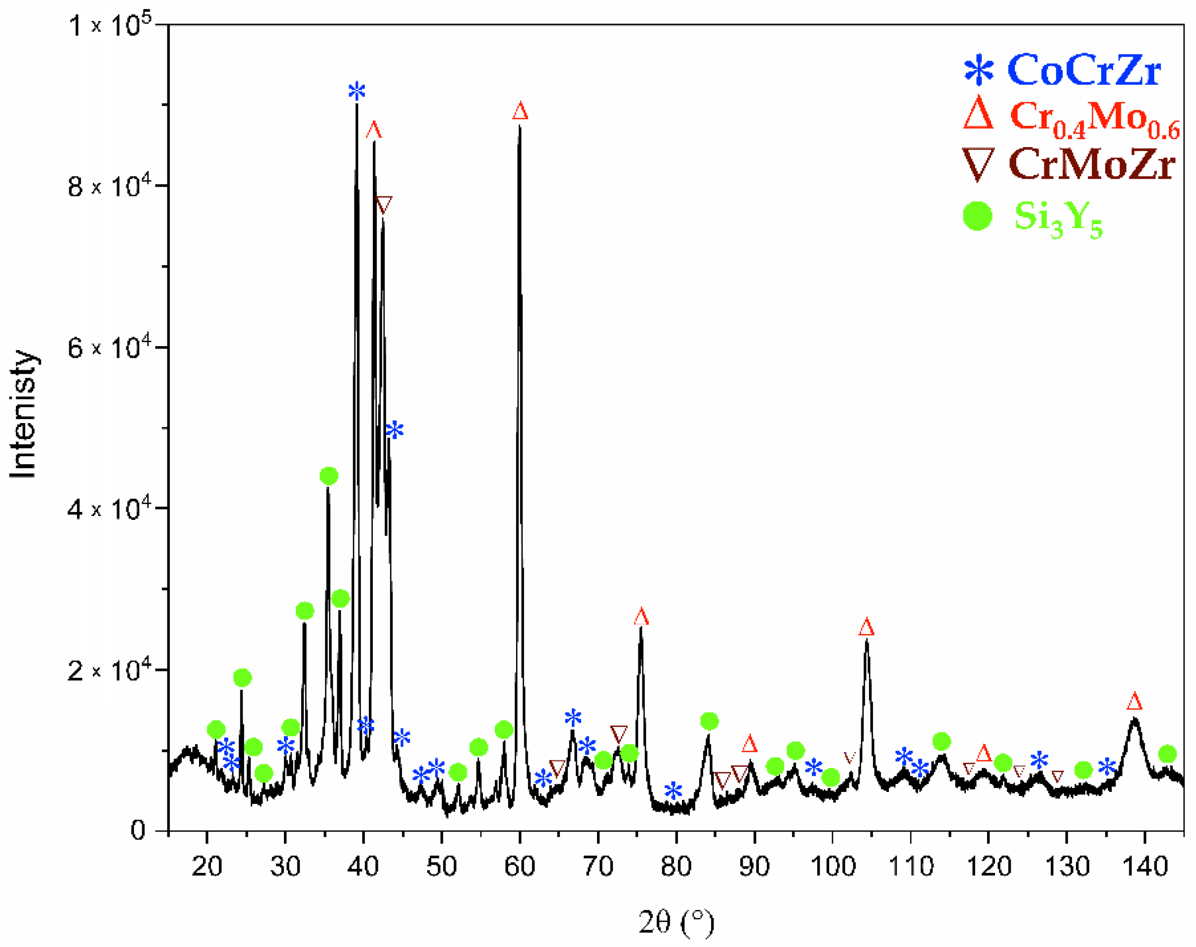
3.1. Phase Analysis

The performed phase analysis revealed the presence of four crystalline phases—two hexagonal and two cubic phases. They were identified by X-ray diffraction phase analysis (Figure 1) based on the standards from ICDD database.
The first identified phase was the hexagonal phase with a structure similar to Si3Y5 (ICDD 04-001-2096) with space group P63/mcm and lattice parameters a0 = 8.44 Å and c0 = 6.35 Å. The highest intensity peak was obtained for 2θ = 35° and represents {112} planes, with ICCD interplanar distance dhkl = 2.53 Å. The second identified phase was a hexagonal CoCrZr-like structure (ICDD 04-003-7686) with space group P63/mmc and lattice parameters from ICCD are a0 = 5.00 Å and c0 = 8.20 Å. The highest intensity peak for that structure was revealed for 2θ = 39°, which corresponds to {200} planes, with ICDD interplanar distance dhkl = 2.17 Å. The third of the identified phases was the cubic phase with a structure similar to Cr0.4Mo0.6 (ICDD 04-018-6044), with space group Im 3 ¯ m and a0 = 3.07 Å ICDD lattice parameter. The highest intensity peak was obtained for 2θ = 59°, which also corresponds to {200} planes with ICDD interplanar distance dhkl = 1.54 Å. The fourth was the cubic phase structure similar to CrMoZr (ICDD 04-015-0011) with space group   Fm 3 ¯ m and lattice parameters a0 = 3.39 Å. The highest intensity peak was obtained for 2θ = 42°, which corresponds to {222} planes with interplanar distance dhkl = 2.13 Å.
For the Cr0.4Mo0.6-like phase, the X-ray-diffraction pattern revealed that peaks were slightly shifted towards lower diffraction angles. It means that there is the increase of the lattice parameter comparing what can be associated with the unit cell expansion due to the presence of higher atomic radii atoms like Y(~1.80 Å). Additionally, due to the highest intensity for peak 2θ = 60° in comparison to other peaks, the presence of texture is highly probable. No significant diffraction peak shifts were observed for the CrMoZr phase. Only for peak 2θ = 72° representing the {440} plane peak was widening observed. It may correspond to a strain in the crystal structure. For the CoCrZr-like phase and Si3Y5-like phase, no significant peak shifts and/or widening were observed. Additionally, the XRD pattern revealed raised backgrounds in the 2θ = 15°–25° and 2θ = 30°–47° regions, which could correspond to the presence of amorphous fractions. In order to confirm the observation, detailed HR TEM studies were performed.
Although the Inoue rules of bulk metallic glasses were fulfilled, the obtained material is mostly crystalline. It is known that the cooling rate has a great influence on the alloy structure formation. A glassy structure forms due to freezing the undercooled liquid to the glass transition temperature Tg. To prevent the transition from a liquid to a crystalline phase, a critical cooling rate has to be exceeded. High cooling rates of 105–106 K·s−1 are required to obtain the amorphous phase [42]. Additionally, up to now, amorphous alloys were obtained by fabrication methods, which ensure reaching a critical cooling rate such as: suction casting (e.g., Ti16.7Zr16.7Hf16.7Cu16.7Ni16.7Be16.7 [43]) or melt spinning (e.g., Pd20Pt20Cu20Ni20P20 [44]).

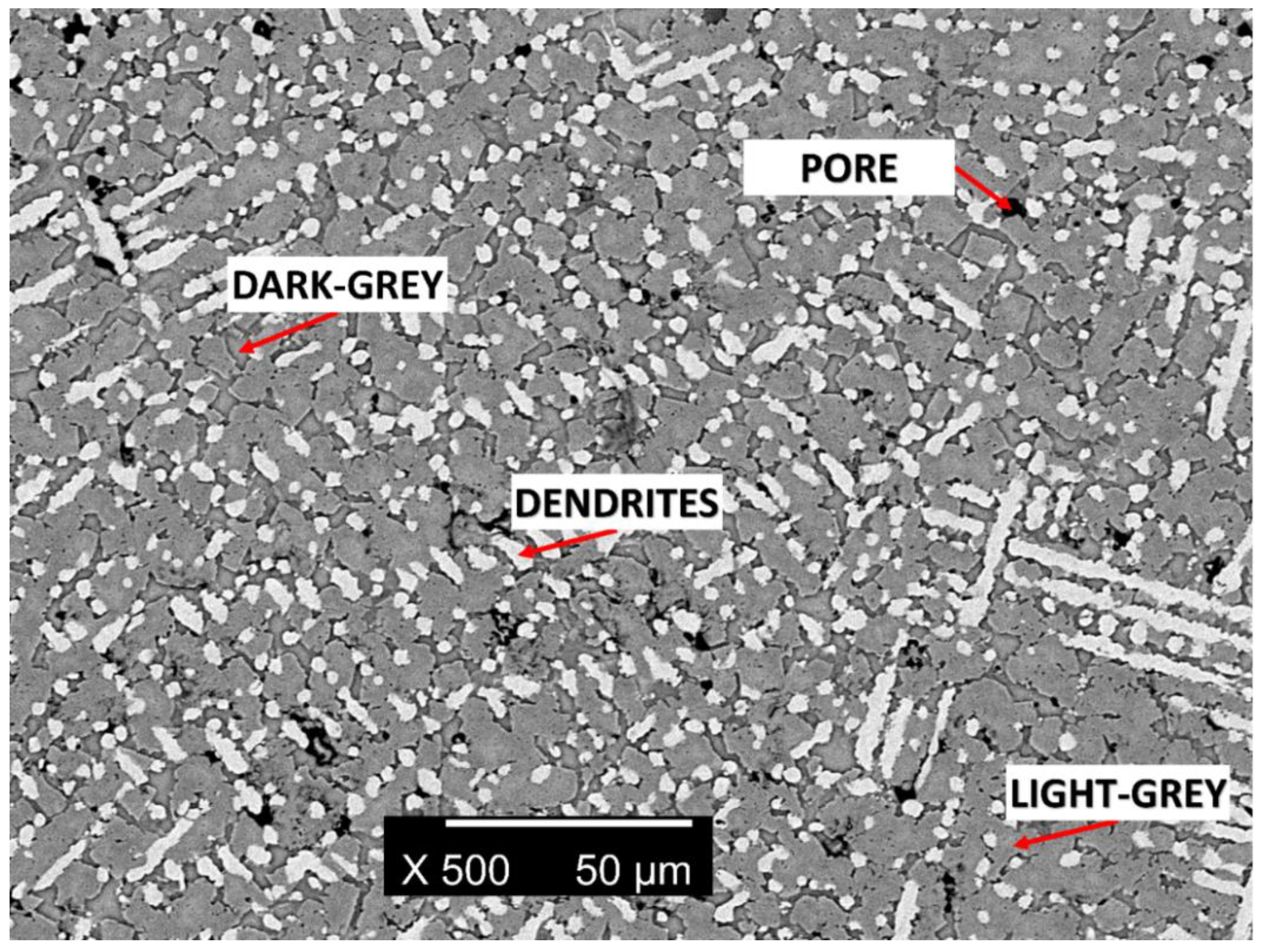
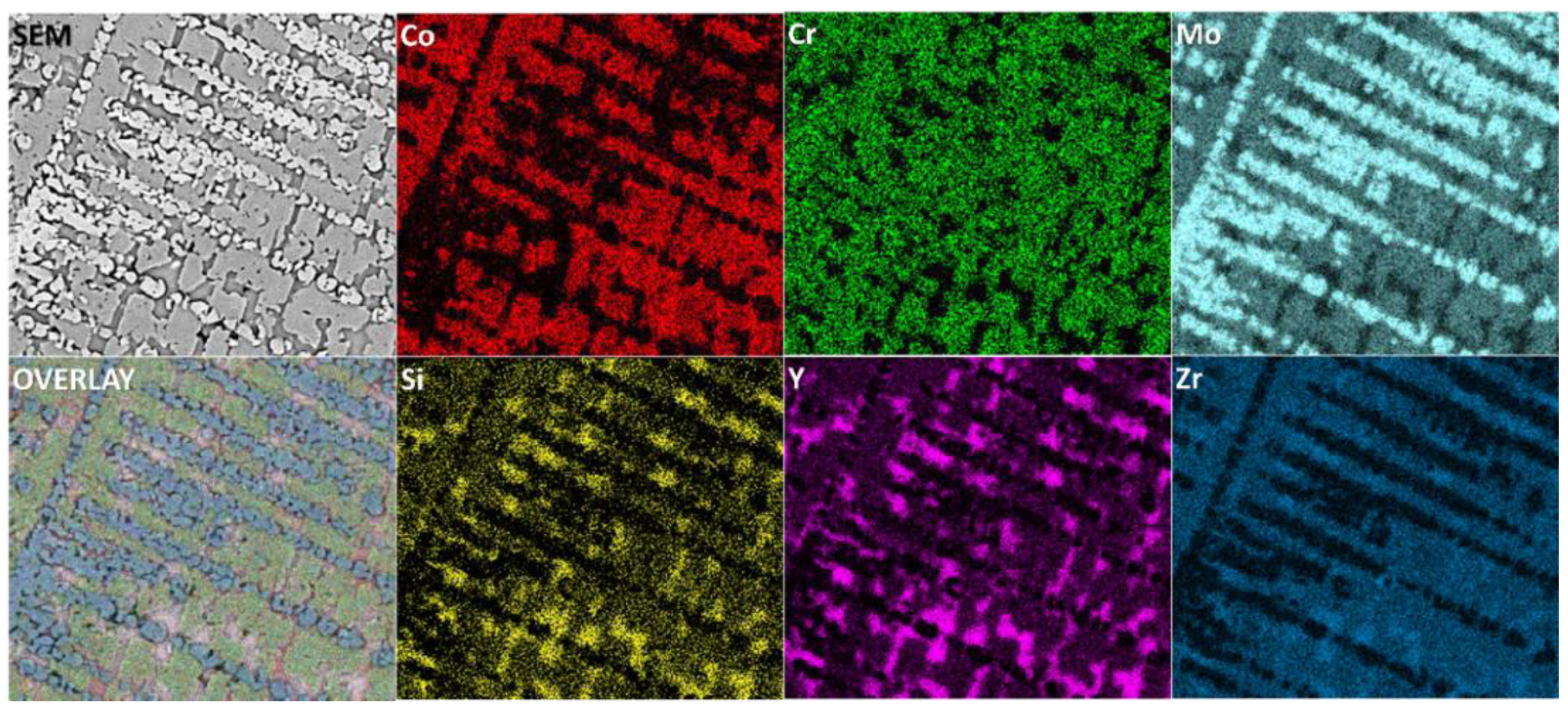
3.2. SEM Microstructure Studies

The microstructure analysis performed using SEM confirmed the presence of a multiphase microstructure. The backscattered electrons contrast image (BSE) (Figure 2) revealed the presence of three phases with different contrasts correlated with the different chemical compositions. The phases were denoted as follows: dendrites, “light-grey”, and “dark-grey”. The fourth phase revealed by X-ray phase analysis was not visible in the BSE image. It is probably due to the fact that there is only a slight difference in the contrast between this phase and one of the others present in the sample. It should be also noted that the alloy microstructure also revealed the presence of pores.
A chemical composition analysis was performed using the EDS technique. For all identified phases, the EDS studies confirmed the presence of all six principal elements. The chemical composition results obtained for all phases are presented in Table 3.
Additionally, using the EDS technique, element distribution maps were obtained (Figure 3). The results confirmed the above-described analysis of the quantitative chemical composition for all phases.
The EDS chemical composition analysis revealed that, for “dendrites” rich in Cr and Mo, they could correspond to the cubic Cr0.4Mo0.6 phase. This is confirmed by the above-described XRD phase analysis. The “light-grey” phase shows enrichment in Co, Cr, Mo, Si, and Zr, which corresponds to the hexagonal CoCrZr and the cubic CrMoZr phases, as is given by the X-ray phase analysis. The last “dark-grey” phase reveals enrichment in Si and Y, which could correspond to the hexagonal Si3Y5 phase.
During solidification from a liquid state, Cr- and Mo-rich dendrites formed primarily due to the highest melting points in comparison to other alloying elements (Cr0.4Mo0.6-like phase). Co, Cr, Zr, and Si segregated in the interdendritic phases due to lower melting points and low miscibility, especially Si and Y with other alloying elements (CoCrZr, CrMoZr, and Si3Y5 phases). The “light-gray” phase can be considered as a five-elemental high entropy alloy. Presence of the Si3Y5 phases observed as “dark-grey” areas can be considered as precipitates. The described elemental segregation of all elements stays in good agreement with the EDS elemental distribution maps (Figure 3).

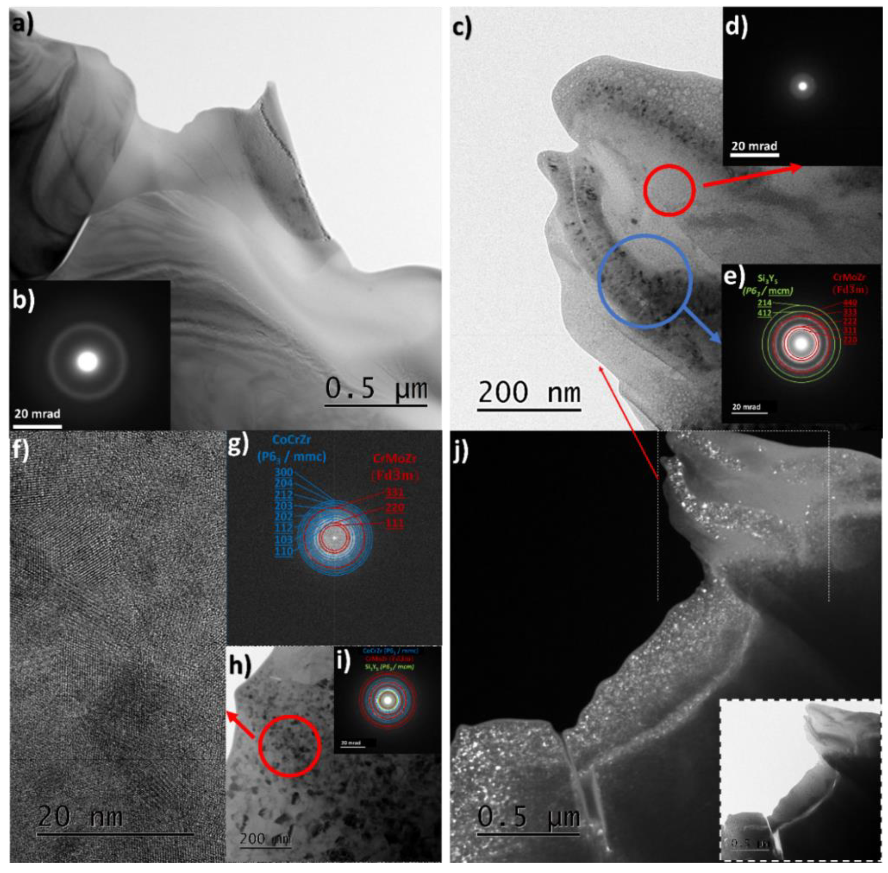
3.3. TEM Microstructure Analysis

A detailed structure analysis was performed using HR TEM in order to examine the possible presence of the amorphous phase in the structure. Additionally, chemical composition using the EDS method was also examined. TEM observations confirmed the existence of amorphous areas revealed by the X-ray diffraction measurements. The wide amorphous regions are present in many regions of the specimen (Figure 4a,b). TEM observations revealed also a mixture of amorphous and nanocrystalline phases (denoted further as the “mixture area”; see Figure 4c—blue circle and Figure 4e) and the presence of purely nanocrystalline areas (Figure 4h,i). The mutual coexistence of the amorphous and nanocrystalline areas in the material could be caused by the nonhomogeneous distribution of elements in the amorphous phase, which results in the faster crystallization of some areas. Crystallization could be also a result of ion beam polishing, which was reported for severely deformed NiTi-shape memory alloy [45]. Nevertheless, the ion beam energy was reduced in order to prevent heating of the specimen during ion polishing, but a crystallization of the amorphous phases could not be excluded. Such a claim can be supported by the fact that the nanocrystalline phase was not observed in the X-ray diffraction measurements. All the observed diffraction peaks were narrow, and only broad amorphous bumps were observed. From the nanocrystalline area, the high-resolution (HR) images were recorded. The observations confirmed presence of nanocrystallites of mixed phases in this area (Figure 4f). The average nanocrystallite size was approximately 23(11) nm. A phase analysis based on the selected area electron diffraction patterns (SAED) indicated that the nanocrystalline phases present in both the nanocrystalline, as well as the mixture areas, are the cubic CrMoZr and hexagonal Si3Y5 (Figure 4e). The interplanar distances obtained from the fast Fourier-transformation image (FFT) (Figure 4g) confirmed the presence of those two phases. Additionally, the SAED patterns taken from the nanocrystalline area (Figure 4i) confirmed the presence of CoCrZr and CrMoZr phases with a small amount of the Si3Y5 phase. The phase analysis based on the FFT image (Figure 4g) and ring SAED pattern (Figure 4i) is in good agreement with TEM EDS chemical composition analysis (see Table 4). TEM EDS chemical composition measurements confirmed the presence of all alloying elements in all the studied areas.
It is highly probable that the presence of nanocrystallites, both in the nanocrystalline areas and mixture areas, could be the result of crystallization of places depleted in Si and Y, since Si and Y exhibit a strong amorphization ability and inhibit crystallization and grain growth. This can be also supported by the fact that amorphous areas are slightly enriched in those elements (TEM EDS analysis). The presence of nanometric sizes of crystallites could be also a result of Zr atoms distribution, which reduced the grain growth, as it was reported in the literature for CrMoZr alloy [46]. In these alloys, the addition of only 2% of Zr significantly reduced the grain size. The chemical composition of the “mixture area” exhibits also high amounts of Si and Y, which means that Si3Y5 crystallites are present there.

3.4. HT DSC Measurements

In order to check the stability of phases in the studied alloy, DSC measurements at high temperatures were performed. Heating and cooling curves in the temperature range from RT up to 1350 °C are shown in Figure 5. For better visualization of the possible phase transformations in the studied alloy also, derivatives versus temperature are shown (inset—Figure 5).
It could be seen that the heating/cooling curves showed no phase transformation nor other thermal effects in the studied temperature range. The obtained results suggest the structural stability of the studied HEA alloy from RT up to 1350 °C. The reversible slope change (also visible on the derivative) on the DSC signal above 600 °C may suggest a change in the heat capacity of the material. This could be a result of a small amount of the amorphous regions in the material and small enthalpy of crystallization.

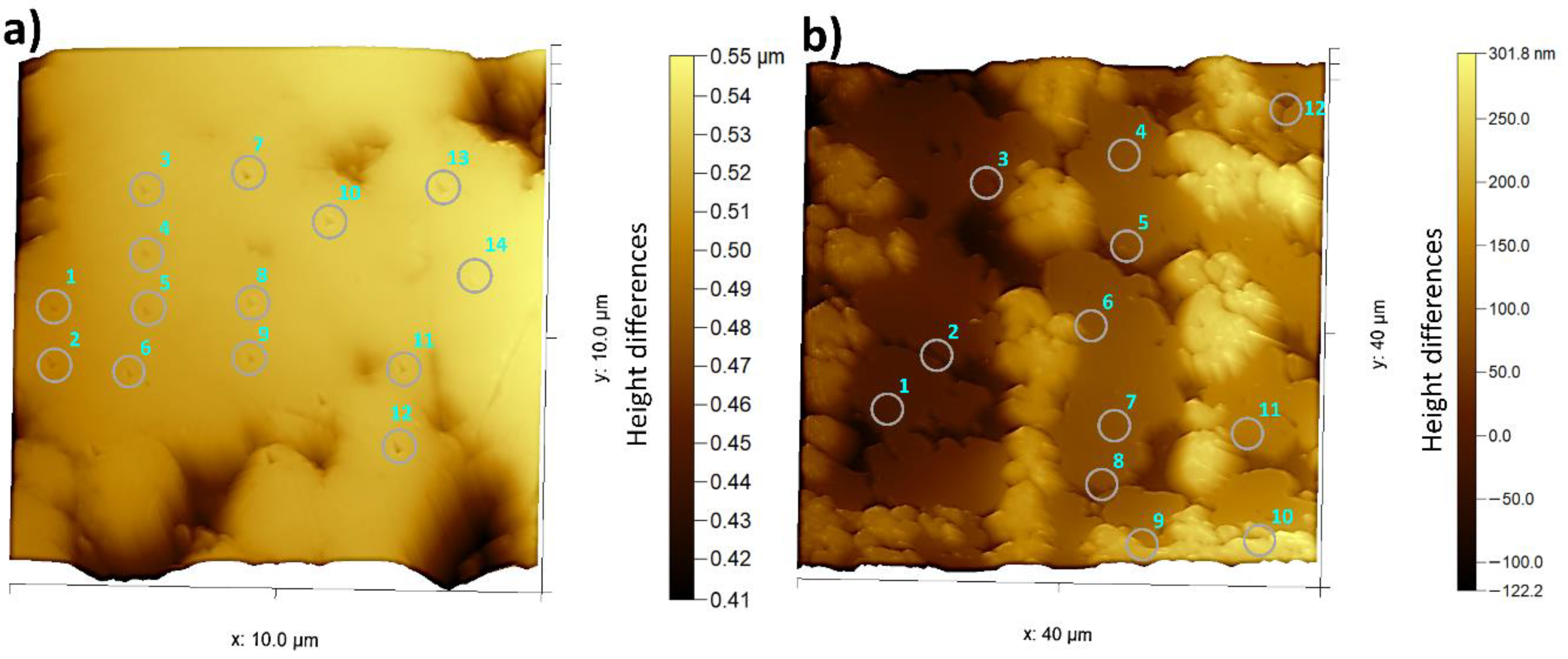
3.5. Mechanical Properties

Nanohardness tests were performed by the nanoindentation technique using a three-sided pyramid Berkovich tip. Sample polishing by SiO2 suspension caused a slight etching of the sample surface and revealed the “dendrites” and “light-grey” phases. Topography images (10-μm × 10-μm area for the dendritic-like phase and 40 μm × 40 μm for the “light—grey” phase) were recorded using scanning mode. The nanoindentation points are labeled in the topography images (Figure 6). One can see that, for both observed phases, there are the traces of the tip inside the circles (Figure 6). For the microhardness and reduced Young’s modulus calculations, only unambiguous indents belonging were taken into account.
The obtained values of nanohardness for the dendrites and “light-grey” phase are HDendrites = 13(2) GPa and HLight-grey = 18(1) GPa, respectively. The reduced Young’s modulus for the dendritic-like and “light-grey” phases are ErDendrites = 185(23) GPa and ErLight-grey = 194(9) GPa, respectively. Both the studied phases differed distinctly in the nanohardness values, whereas the obtained values of the reduced Young’s modulus are similar within the standard deviation. The obtained nanohardness and reduced Young’s modulus values were compared with the literature data and presented in Table 5.
The reduced Young’s modulus is comparable to the other high entropy alloys reported in the literature, like CoCrFeNiAl0.3 [49]. Nevertheless, the silicon and yttrium are present in all the phases observed in the microstructure and can cause a significant increase in hardness of the obtained Co15Cr15Mo25Si15Y15Zr15 high entropy alloy. Such a phenomenon was also reported for the CoCrFeNiY0.3 alloy [51], where a 3% addition of Y increased both the nanohardness and Young’s modulus. For Si containing a Tribaloy (Co-Cr-Mo-Si) [47], it was revealed that a 1% Si addition also significantly increased the nanohardness and Young’s modulus.
Due to the presence of a multiphase structure and amorphous regions, the studied material is brittle. This can be a drawback for their potential applications. However, the amorphous phase could be achieved by changes in the chemical composition, such as: increasing the concentration of Si and Y and their amorphization abilities in comparison to other alloying elements. On the other hand, modification of the production method in order to reach the critical cooling rate could increase the probability of the formation of the amorphous phase.

4. Conclusions

The six-elemental high entropy Co15Cr15Mo25Si15Y15Zr15 alloy was obtained using the vacuum arc melting technique. The XRD phase analysis revealed the multiphase structure of the alloy, including the presence of the amorphous phase. SEM EDS and TEM EDS chemical analysis revealed that all six alloying elements are present in all the observed phases. The existence of amorphous regions was confirmed by TEM analysis. The TEM phase analysis of ring electron diffraction patterns confirmed XRD phase analysis. HT DSC measurements did not reveal any additional phase transformation during the heating (and cooling) up to 1350 °C. The solid-state crystallization process was also not observed due to a relatively low amount of the amorphous phase. The mechanical tests revealed an increase of the reduced Young’s modulus and nanohardness, which were caused by the Si and Y additions. The obtained results are comparable to data reported for the other high entropy alloys.
Nonetheless, the presented results showed that the examined alloy is a good candidate for metal glass material.

Author Contributions

Conceptualization, K.G., P.Ś., M.Z., and D.S.; methodology, K.G., M.Z., J.L., and P.Ś.; resources and material manufacturing, K.P. and R.A.; investigation, K.G., M.Z., J.L., and B.W.; writing—original draft preparation, K.G.; and data analysis, K.G., P.Ś. M.Z., G.D., and D.S. All authors contributed to writing—review and editing. All authors have read and agreed to the published version of the manuscript.

Funding

This research received no external funding.

Acknowledgments

We would like to thank Yong Yang and his collaborators from The Hong Kong University of Science and Technology for help in the calculations of excess mixing entropy to calculate the ϕ thermodynamic parameter.

Conflicts of Interest

The authors declare no conflict of interest.

References

  1. Cantor, B.; Chang, I.T.H.; Knight, P.; Vincent, A.J.B. Microstructural development in equiatomic multicomponent alloys. Mater. Sci. Eng. A 2004, 375, 213–218. [Google Scholar] [CrossRef]
  2. Yeh, J.-W. Overview of High-Entropy Alloys. In High-Entropy Alloys: Fundamentals and Applications; Gao, M.C., Yeh, J.-W., Liaw, P.K., Zhang, Y., Eds.; Springer International Publishing: Cham, Switzerland, 2016; pp. 1–19. ISBN 978-3-319-27013-5. [Google Scholar]
  3. Steurer, W. Single-phase high-entropy alloys—A critical update. Mater. Charact. 2020, 162, 110179. [Google Scholar] [CrossRef]
  4. Chen, T.K.; Wong, M.S.; Shun, T.T.; Yeh, J.W. Nanostructured nitride films of multi-element high-entropy alloys by reactive DC sputtering. Surf. Coat. Technol. 2005, 200, 1361–1365. [Google Scholar] [CrossRef]
  5. Hsu, C.-Y.; Yeh, J.-W.; Chen, S.-K.; Shun, T.-T. Wear resistance and high-temperature compression strength of Fcc CuCoNiCrAl0.5Fe alloy with boron addition. Metall. Mater. Trans. A 2004, 35, 1465–1469. [Google Scholar] [CrossRef]
  6. Huang, P.-K.; Yeh, J.-W.; Shun, T.-T.; Chen, S.-K. Multi-Principal-Element Alloys with Improved Oxidation and Wear Resistance for Thermal Spray Coating. Adv. Eng. Mater. 2004, 6, 74–78. [Google Scholar] [CrossRef]
  7. Yeh, J.-W.; Lin, S.-J.; Chin, T.-S.; Gan, J.-Y.; Chen, S.-K.; Shun, T.-T.; Tsau, C.-H.; Chou, S.-Y. Formation of simple crystal structures in Cu-Co-Ni-Cr-Al-Fe-Ti-V alloys with multiprincipal metallic elements. Metall. Mater. Trans. A 2004, 35, 2533–2536. [Google Scholar] [CrossRef]
  8. Yeh, J.-W.; Chen, S.-K.; Lin, S.-J.; Gan, J.-Y.; Chin, T.-S.; Shun, T.-T.; Tsau, C.-H.; Chang, S.-Y. Nanostructured High-Entropy Alloys with Multiple Principal Elements: Novel Alloy Design Concepts and Outcomes. Adv. Eng. Mater. 2004, 6, 299–303. [Google Scholar] [CrossRef]
  9. Zhang, Y.; Zuo, T.; Cheng, Y.; Liaw, P.K. High-entropy alloys with high saturation magnetization, electrical resistivity, and malleability. Sci. Rep. 2013, 3, 1455. [Google Scholar] [CrossRef] [PubMed] [Green Version]
  10. Gludovatz, B.; Hohenwarter, A.; Catoor, D.; Chang, E.H.; George, E.P.; Ritchie, R.O. A fracture-resistant high-entropy alloy for cryogenic applications. Science 2014, 345, 1153–1158. [Google Scholar] [CrossRef] [PubMed] [Green Version]
  11. Lu, Y.; Dong, Y.; Guo, S.; Jiang, L.; Kang, H.; Wang, T.; Wen, B.; Wang, Z.; Jie, J.; Cao, Z.; et al. A promising new class of high-temperature alloys: Eutectic high-entropy alloys. Sci. Rep. 2014, 4, 6200. [Google Scholar] [CrossRef]
  12. Senkov, O.N.; Wilks, G.B.; Miracle, D.B.; Chuang, C.P.; Liaw, P.K. Refractory high-entropy alloys. Intermetallics 2010, 18, 1758–1765. [Google Scholar] [CrossRef]
  13. Biesiekierski, A.; Wang, J.; Abdel-Hady Gepreel, M.; Wen, C. A new look at biomedical Ti-based shape memory alloys. Acta Biomater. 2012, 8, 1661–1669. [Google Scholar] [CrossRef] [PubMed]
  14. Wang, S.P.; Xu, J. TiZrNbTaMo high-entropy alloy designed for orthopedic implants: As-cast microstructure and mechanical properties. Mater. Sci. Eng. C 2017, 73, 80–89. [Google Scholar] [CrossRef] [PubMed]
  15. Glowka, K.; Zubko, M.; Swiec, P.; Prusik, K.; Dercz, G.; Stróz, D. Microstructure analysis of equiatomic multi-component Ni20Ti20Ta20Co20Cu20 alloy. Arch. Metall. Mater. 2019, 64, 785–789. [Google Scholar] [CrossRef]
  16. Glowka, K.; Zubko, M.; Swiec, P.; Prusik, K.; Dercz, G.; Matyja, E.; Stróz, D. Microstructure of multi-component Ni35Ti35Ta10Co10Cu10 alloy. Arch. Metall. Mater. 2019, 64, 715–719. [Google Scholar] [CrossRef]
  17. Chen, C.H.; Chen, Y.J. Shape memory characteristics of (TiZrHf)50Ni25Co10Cu15 high entropy shape memory alloy. Scr. Mater. 2019, 162, 185–189. [Google Scholar] [CrossRef]
  18. MacDonald, B.E.; Fu, Z.; Zheng, B.; Chen, W.; Lin, Y.; Chen, F.; Zhang, L.; Ivanisenko, J.; Zhou, Y.; Hahn, H.; et al. Recent Progress in High Entropy Alloy Research. JOM 2017, 69, 2024–2031. [Google Scholar] [CrossRef]
  19. Miracle, D.B.; Senkov, O.N. A critical review of high entropy alloys and related concepts. Acta Mater. 2017, 122, 448–511. [Google Scholar] [CrossRef] [Green Version]
  20. Takeuchi, A.; Amiya, K.; Wada, T.; Yubuta, K.; Zhang, W.; Makino, A. Entropies in Alloy Design for High-Entropy and Bulk Glassy Alloys. Entropy 2013, 15, 3810–3821. [Google Scholar] [CrossRef]
  21. Xing, Q.W.; Zhang, Y. Amorphous phase formation rules in high-entropy alloys. Chin. Phys. B 2017, 26, 18104. [Google Scholar] [CrossRef]
  22. Yang, Y.; Ye, Y.F.; Liu, C.T.; Lu, J.; Wang, Q. High-entropy alloy: Challenges and prospects. Mater. Today 2015, 19, 349–362. [Google Scholar] [CrossRef]
  23. Nong, Z.-S.; Zhu, J.-C.; Cao, Y.; Yang, X.-W.; Lai, Z.-H.; Liu, Y. Stability and structure prediction of cubic phase in as cast high entropy alloys. Mater. Sci. Technol. 2014, 30, 363–369. [Google Scholar] [CrossRef]
  24. Pitzer, K.S. The Nature of the Chemical Bond and the Structure of Molecules and Crystals: An Introduction to Modern Structural Chemistry. J. Am. Chem. Soc. 1960, 82, 4121. [Google Scholar] [CrossRef]
  25. Dong, Y.; Lu, Y.; Jiang, L.; Wang, T.; Li, T. Effects of electro-negativity on the stability of topologically close-packed phase in high entropy alloys. Intermetallics 2014, 52, 105–109. [Google Scholar] [CrossRef]
  26. Yang, X.; Zhang, Y. Prediction of high-entropy stabilized solid-solution in multi-component alloys. Mater. Chem. Phys. 2012, 132, 233–238. [Google Scholar] [CrossRef]
  27. Ye, Y.F.; Wang, Q.; Lu, J.; Liu, C.T.; Yang, Y. The generalized thermodynamic rule for phase selection in multicomponent alloys. Intermetallics 2015, 59, 75–80. [Google Scholar] [CrossRef]
  28. Wang, Z.; Huang, Y.; Yang, Y.; Wang, J.; Liu, C.T. Atomic-size effect and solid solubility of multicomponent alloys. Scr. Mater. 2015, 94, 28–31. [Google Scholar] [CrossRef]
  29. Inoue, A. Stabilization of metallic supercooled liquid and bulk amorphous alloys. Acta Mater. 2000, 48, 279–306. [Google Scholar] [CrossRef]
  30. Lu, Z.P.; Liu, C.T. Role of minor alloying additions in formation of bulk metallic glasses: A review. J. Mater. Sci. 2004, 39, 3965–3974. [Google Scholar] [CrossRef]
  31. Choi-Yim, H.; Busch, R.; Johnson, W.L. The effect of silicon on the glass forming ability of the Cu47Ti34Zr11Ni8 bulk metallic glass forming alloy during processing of composites. J. Appl. Phys. 1998, 83, 7993–7997. [Google Scholar] [CrossRef]
  32. Yi, S.; Park, T.G.; Kim, D.H. Ni-based bulk amorphous alloys in the Ni-Ti-Zr-(Si,Sn) system. J. Mater. Res. 2000, 15, 2425–2430. [Google Scholar] [CrossRef]
  33. Inoue, A.; Murakami, A.; Zhang, T.; Takeuchi, A. Thermal stability and magnetic properties of bulk amorphous Fe-Al-Ga-P-C-B-Si alloys. Mater. Trans. JIM 1997, 38, 189–196. [Google Scholar] [CrossRef] [Green Version]
  34. Yazici, Z.O.; Hitit, A.; Yalcin, Y.; Ozgul, M. Effects of minor Cu and Si additions on glass forming ability and mechanical properties of Co-Fe-Ta-B Bulk metallic glass. Met. Mater. Int. 2016, 22, 50–57. [Google Scholar] [CrossRef]
  35. Zhang, T.; Kurosaka, K.; Inoue, A. Thermal and mechanical properties of Cu-based Cu-Zr-Ti-Y bulk glassy alloys. Mater. Trans. 2001, 42, 2042–2045. [Google Scholar] [CrossRef]
  36. Lu, Z.P.; Liu, C.T.; Porter, W.D. Role of yttrium in glass formation of Fe-based bulk metallic glasses. Appl. Phys. Lett. 2003, 83, 2581–2583. [Google Scholar] [CrossRef]
  37. Lu, Z.P.; Liu, C.T.; Carmichael, C.A.; Porter, W.D.; Deevi, S.C. Bulk glass formation in an Fe-Based Fe-Y-Zr-M (M = Cr, Co, Al)-Mo-B system. J. Mater. Res. 2004, 19, 921–929. [Google Scholar] [CrossRef]
  38. Park, J.M.; Park, J.S.; Na, J.H.; Kim, D.H.; Kim, D.H. Effect of Y addition on thermal stability and the glass forming ability in Fe-Nb-B-Si bulk glassy alloy. Mater. Sci. Eng. A 2006, 435–436, 425–428. [Google Scholar] [CrossRef]
  39. Figueroa, I.A.; Davies, H.A.; Todd, I. High glass formability for Cu-Hf-Ti alloys with small additions of y and Si. Philos. Mag. 2009, 89, 2355–2368. [Google Scholar] [CrossRef]
  40. Guo, S.; Liu, C.T. Phase stability in high entropy alloys: Formation of solid-solution phase or amorphous phase. Prog. Nat. Sci. Mater. Int. 2011, 21, 433–446. [Google Scholar] [CrossRef] [Green Version]
  41. Skriver, H.L. Crystal structure from one-electron theory. Phys. Rev. B 1985, 31, 1909–1923. [Google Scholar] [CrossRef]
  42. Wang, W.H. Roles of minor additions in formation and properties of bulk metallic glasses. Prog. Mater. Sci. 2007, 52, 540–596. [Google Scholar] [CrossRef]
  43. Tong, Y.; Qiao, J.C.; Zhang, C.; Pelletier, J.M.; Yao, Y. Mechanical properties of Ti16.7Zr16.7Hf16.7Cu16.7Ni16.7Be16.7 high-entropy bulk metallic glass. J. Non-Cryst. Solids 2016, 452, 57–61. [Google Scholar] [CrossRef]
  44. Takeuchi, A.; Chen, N.; Wada, T.; Yokoyama, Y.; Kato, H.; Inoue, A.; Yeh, J.W. Pd20Pt20Cu20Ni20P20 high-entropy alloy as a bulk metallic glass in the centimeter. Intermetallics 2011, 19, 1546–1554. [Google Scholar] [CrossRef]
  45. Swiec, P.; Zubko, M.; Stróz, D.; Lekston, Z. Analysis of amorphous regions in severely marformed NiTi shape memory alloy. Int. J. Mater. Res. 2019, 110, 18–23. [Google Scholar] [CrossRef]
  46. Lai, C.H.; Chen, W.C.; Tsai, P.H.; Ding, I.P. Effects of alloying additions in the CrMo underlayer on the grain size and magnetic properties of CoCrPt longitudinal media. J. Appl. Phys. 2003, 93, 8468–8470. [Google Scholar] [CrossRef]
  47. Liu, R.; Yao, J.; Zhang, Q.; Yao, M.X.; Collier, R. Effects of Silicon Content on the Microstructure and Mechanical Properties of Cobalt-Based Tribaloy Alloys. J. Eng. Mater. Technol. Trans. ASME 2016, 138, 2–8. [Google Scholar] [CrossRef]
  48. Yao, M.X.; Wu, J.B.C.; Liu, R. Microstructural characteristics and corrosion resistance in molten Zn-Al bath of Co-Mo-Cr-Si alloys. Mater. Sci. Eng. A 2005, 407, 299–305. [Google Scholar] [CrossRef]
  49. Liao, W.; Lan, S.; Gao, L.; Zhang, H.; Xu, S.; Song, J.; Wang, X.; Lu, Y. Nanocrystalline high-entropy alloy (CoCrFeNiAl0.3) thin-film coating by magnetron sputtering. Thin Solid Films 2017, 638, 383–388. [Google Scholar] [CrossRef]
  50. Sun, Y.; Chen, P.; Liu, L.; Yan, M.; Wu, X.; Yu, C.; Liu, Z. Local mechanical properties of AlxCoCrCuFeNi high entropy alloy characterized using nanoindentation. Intermetallics 2018, 93, 85–88. [Google Scholar] [CrossRef]
  51. Zhang, L.J.; Zhang, M.D.; Zhou, Z.; Fan, J.T.; Cui, P.; Yu, P.F.; Jing, Q.; Ma, M.Z.; Liaw, P.K.; Li, G.; et al. Effects of rare-earth element, Y, additions on the microstructure and mechanical properties of CoCrFeNi high entropy alloy. Mater. Sci. Eng. A 2018, 725, 437–446. [Google Scholar] [CrossRef] [Green Version]
  52. Ma, Y.; Feng, Y.H.; Debela, T.T.; Peng, G.J.; Zhang, T.H. Nanoindentation study on the creep characteristics of high-entropy alloy films: Fcc versus bcc structures. Int. J. Refract. Met. Hard Mater. 2016, 54, 395–400. [Google Scholar] [CrossRef]
  53. Ganji, R.S.; Karthik, P.S.; Rao, K.B.S.; Rajulapati, K.V. Strengthening mechanisms in equiatomic ultrafine grained AlCoCrCuFeNi high-entropy alloy studied by micro- and nanoindentation methods. Acta Mater. 2017, 125, 58–68. [Google Scholar] [CrossRef]
  54. Maier-Kiener, V.; Schuh, B.; George, E.P.; Clemens, H.; Hohenwarter, A. Nanoindentation testing as a powerful screening tool for assessing phase stability of nanocrystalline high-entropy alloys. Mater. Des. 2017, 115, 479–485. [Google Scholar] [CrossRef] [Green Version]
  55. Sinha, S.; Mirshams, R.A.; Wang, T.; Nene, S.S.; Frank, M.; Liu, K.; Mishra, R.S. Nanoindentation behavior of high entropy alloys with transformation-induced plasticity. Sci. Rep. 2019, 9, 6639. [Google Scholar] [CrossRef]
  56. Sinha, S.; Nene, S.S.; Frank, M.; Liu, K.; Mishra, R.S.; McWilliams, B.A.; Cho, K.C. Revealing the microstructural evolution in a high entropy alloy enabled with transformation, twinning and precipitation. Materialia 2019, 6, 100310. [Google Scholar] [CrossRef]
  57. Nene, S.S.; Sinha, S.; Frank, M.; Liu, K.; Mishra, R.S.; McWilliams, B.A.; Cho, K.C. Unexpected strength–ductility response in an annealed, metastable, high-entropy alloy. Appl. Mater. Today 2018, 13, 198–206. [Google Scholar] [CrossRef]
  58. Nene, S.S.; Frank, M.; Liu, K.; Sinha, S.; Mishra, R.S.; McWilliams, B.; Cho, K.C. Reversed strength-ductility relationship in microstructurally flexible high entropy alloy. Scr. Mater. 2018, 154, 163–167. [Google Scholar] [CrossRef]
  59. Jiao, Z.M.; Chu, M.Y.; Yang, H.J.; Wang, Z.H.; Qiao, J.W. Nanoindentation characterised plastic deformation of a Al0.5CoCrFeNi high entropy alloy. Mater. Sci. Technol. 2015, 31, 1244–1249. [Google Scholar] [CrossRef]
  60. Sun, Y.; Zhao, G.; Wen, X.; Qiao, J.; Yang, F. Nanoindentation deformation of a bi-phase AlCrCuFeNi2 alloy. J. Alloys Compd. 2014, 608, 49–53. [Google Scholar] [CrossRef]
  61. Coury, F.G.; Wilson, P.; Clarke, K.D.; Kaufman, M.J.; Clarke, A.J. High-throughput solid solution strengthening characterization in high entropy alloys. Acta Mater. 2019, 167, 1–11. [Google Scholar] [CrossRef]
  62. Wu, D.; Jang, J.S.C.; Nieh, T.G. Elastic and plastic deformations in a high entropy alloy investigated using a nanoindentation method. Intermetallics 2016, 68, 118–127. [Google Scholar] [CrossRef] [Green Version]
Figure 1. X-ray diffraction pattern for the studied Co15Cr15Mo25Si15Y15Zr15 alloy with indexed phases.
Metals 10 01456 g001
Figure 2. Backscattered electrons contrast image (BSE) of the sample microstructure with the assigned phases and pores.
Metals 10 01456 g002
Figure 3. SEM energy-dispersive X-ray spectroscopy (EDS) elemental distribution maps in the studied alloy.
Metals 10 01456 g003
Figure 4. Bright field image of the amorphous area (a) with corresponding selected area electron diffraction (SAED) pattern (b), bright field of the amorphous area (red circle) (c) with corresponding SAED pattern (d), bright field of a mixture of amorphous and nanocrystalline area (blue circle) (c) with corresponding SAED pattern (e), high-resolution image nanocrystalline area (f) with Fourier-transformation image corresponding to HR image (g), bright field image of the nanocrystalline area (h) with corresponding SAED pattern (i), and bright field and dark field images of the amorphous and mixture of amorphous and nanocrystalline areas (j).
Metals 10 01456 g004
Figure 5. Differential scanning calorimetry (DSC) heating/cooling curves for the studied alloy.
Metals 10 01456 g005
Figure 6. 3D topography image with assigned tip places for the dendritic-like phase (a) and for the “light-grey” phase (b).
Metals 10 01456 g006
Table 1. Physical properties of pure alloying elements: crystal structure, atomic radius (ri), valence electron concentration (VEC)i, melting point (Tm)i, and Pauling’s electronegativity (χi) [40,41]. BCC: body-centered cubic, FCC: face-centered cubic and HCP: hexagonal closest packed.
ElementCrystal Structureri (Å)(VEC)i(Tm)I (K)χi (Pauling Units)
CoHCP1.251917681.88
CrBCC1.249621801.66
MoBCC1.363628962.16
SiFCC1.153416871.90
YHCP1.802317981.22
ZrHCP1.603421231.33
Table 2. Thermodynamic parameters calculated for the Co15Cr15Mo25Si15Y15Zr15 alloy: atomic size mismatch (δ), mixing enthalpy (ΔHmix), mixing entropy (ΔSmix), electronegativity differences (Δχ), valence electron concentration (VEC), Yang et al. parameter (Ω), Ye et al. parameter (ϕ), atomic packing misfit, and topological instability parameter (γ).
δ (%)ΔHmix (kJ∙mol−1)ΔSmix (J(mol·K)−1)Δχ (eV)VECΩ [26]Φ [27]γ [28]
ξ = 0.68ξ = 0.74
15.44−29.4914.71
(1.769∙R)
0.345.401.082.801.731.626
Table 3. SEM energy-dispersive X-ray spectroscopy (EDS) chemical composition (at.%) of all phases in the studied alloy.
Studied AreaCoCrMoSiYZr
Dendrites2.4(7)29.3(7)66.7(8)0.9(4)0.4(1)0.3(8)
Light-grey phase22.6(6)24.5(8)14.4(8)12.0(3)3.3(3)23.2(7)
Dark-grey phase1.6(7)1.8(7)1.9(7)33.2(8)59.7(6)1.8(9)
Table 4. TEM EDS chemical composition (at.%) of all phases in the studied alloys.
Studied AreaCoCrMoSiYZr
Amorphous30.0(2)17.4(2)15.9(2)4.5(2)7.8(2)24.4(2)
Mixture20.6(2)16.8(2)10.7(1)16.5(1)18.8(1)16.6(1)
Nanocrystalline30.3(2)17.3(2)19.2(2)3.6(2)5.7(2)23.9(1)
Table 5. Obtained nanohardness (H) and reduced Young’s modulus (Er) for the studied alloys in comparison to the literature-described high entropy alloy compositions.
Chemical CompositionNanohardness
H (GPa)
Reduced Young’s Modulus
Er (GPa)
Reference
Co15Cr15Mo25Si15Y15Zr15
Light-grey
17.88193.81present study
Co15Cr15Mo25Si15Y15Zr15
Dendrites
13.26184.51present study
Co60.4Cr8.5Mo28.5Si2.6
Laves phase
21.81397.50[47]
Co60.4Cr8.5Mo28.5Si2.621.80398.00[48]
Co60.4Cr8.5Mo28.5Si2.6
Solid solution
13.78310.52[47]
CoCrFeNiAl0.312.28197.44[49]
Co59.8Cr17Mo22Si1.2
Laves phase
11.38270.48[47]
Al3CoCrCuFeNi10.50260.00[50]
CoCrFeNiY0.3
Hexagonal phase
10.50215.00[51]
CoCrFeNiCuAl2.59.20174.30[52]
AlCoCrCuFeNi8.13172.00[53]
CrMnFeCoNi7.64252.00[54]
Co59.8Cr17Mo22Si1.2
Solid solution
7.48274.03[47]
CoCrFeNiCu7.30188.50[52]
Fe38.5Mn20Co20Cr15Si5Cu1.56.83192.60[55,56]
Fe39Mn20Co20Cr15Si5Al16.38205.70[55,57]
Fe40Mn20Co20Cr15Si55.33156.00[55,58]
Al0.5CoCrFeNi4.64220.84[59]
AlCrCuFeNi2 (BCC)4.60146.00[60]
CrMnFeCoNi4.44205.00[61]
CoCrFeNiY0.3
FCC phase
3.30190.00[51]
CoCrFeNiY0
FCC phase
2.90185.00[51]
AlCrCuFeNi2 (FCC)2.80207.00[60]
NiFeCoCrMn1.88190.21[62]
Publisher’s Note: MDPI stays neutral with regard to jurisdictional claims in published maps and institutional affiliations.

