Article

Study on Tooth Interior Fatigue Fracture Failure of Wind Turbine Gears

1
State Key Laboratory of Mechanical Transmissions, Chongqing University, Chongqing 400030, China
2
Chongqing Wangjiang Industry Co., Ltd., Chongqing 400071, China
3
College of Aerospace Engineering, Chongqing University, Chongqing 400044, China
*
Authors to whom correspondence should be addressed.
Metals 2020, 10(11), 1497; https://doi.org/10.3390/met10111497
Submission received: 26 October 2020 / Revised: 6 November 2020 / Accepted: 6 November 2020 / Published: 10 November 2020

Abstract

:
Gear contact fatigue has becoming a bottleneck restricting the safety and reliability of wind turbine transmission systems. Tooth interior fatigue fracture (TIFF) failure is commonly observed in case-hardened wind turbine gears. In this work, a contact fatigue model is developed to investigate the effect of design parameters and material properties on TIFF of wind turbine gears. The sub-surface stress field is obtained by superposing the load-introduced stress and initial residual stress. The hardness gradient of the hardened layer is measured by Vickers hardness tests. Based upon the stress field and material properties, a fatigue parameter analysis is presented to characterize the risk of TIFF by using the Dang Van multiaxial fatigue criterion. Results show that the risk of TIFF increases with increasing external load. Increasing pressure angle and residual compressive stress could reduce TIFF risk. The combination of high surface hardness, low core hardness, and large effective case depth could inhibit the crack initiation.

1. Introduction

Wind turbines are usually installed on wild fields or offshore. The service life of wind turbines reaches up to 20–30 years, which is a significant challenge to the design and maintenance. Gear contact fatigue has become a bottleneck, restricting the safety and reliability of wind turbine transmission systems as harsh working conditions and higher power density are developed. Typical contact failures of gears include micropitting, pitting, and scuffing. Such forms of failure have corresponding design methods and technical requirements in IEC6140-4 wind power gearbox design specifications [1] and the DNV GL wind power gearbox certification guide [2]. In addition to the above typical contact failure types is tooth fatigue interior fracture (TIFF) failure, as reported in heavy-duty wind turbine gearboxes, which is significantly different from pitting and tooth breakage.
From the perspective of the failure mechanism, micropitting and pitting are caused by the initiation and propagation of cracks on or near the surface of the gears. The stress concentration and fluctuation near the surface is one of the main contributors. However, the initiation cracks of TIFF are usually observed in the interface of the case-hardened layer and core. In addition, the difference between the TIFF and the tooth root fatigue fracture is that the TIFF is manifested as a fracture in the mid-height of the tooth profile, while a tooth root break is triggered by a crack near the tooth root [3]. As shown in Figure 1, TIFF is also referred to as tooth fatigue fracture (TFF), which is usually observed when the gear is loaded on both sides [4]. In this work, these two fatigue failure types are not distinguished, since there are many common features as follow:
(1)
TIFF is commonly reported in heavy-duty carburized gears.
(2)
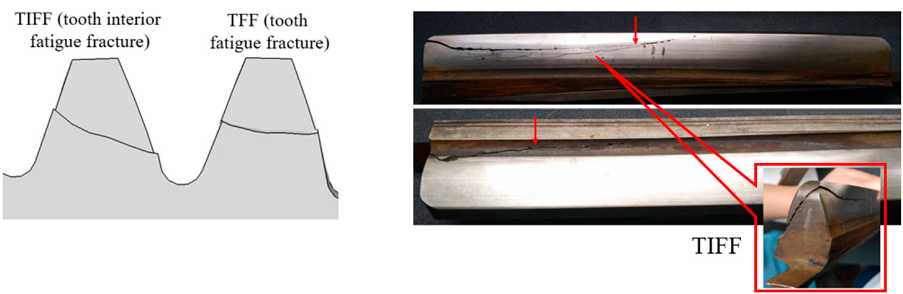
The fracture section is usually observed in the mid-height of the tooth.
(3)
The main crack of TIFF is at an angle of 40–50° with the tooth surface.
(4)
Most of the failure gears caused by TIFF do not show micropitting or pitting on the tooth surface.
(5)
Crack initiation occurs at the junction between the hardened layer and the core and is often accompanied by non-metallic inclusion, as shown in Figure 2.
Over the past decades, special attention has been given to TIFF by FZG [5], SMT [6], KISSsoft [7], and other gear research institutions. MackAldener and Olsson [8,9] studied the influence of geometrical parameters, material strength, and carburized layer depth on TIFF by using the finite element method. Al et al. [10] summarized the calculation method of TIFF into four steps: stress history analysis, residual stress analysis, multiaxial fatigue criterion selection, and failure risk assessment. Based on the ISO/TS 6336-4 [11] calculation method, Hein et al. [12] studied the influence of different parameters on the TIFF failure risk of gears. Octrue et al. [13] established the TIFF failure evaluation model by integrating the CAE analysis method and multiaxial fatigue criteria, and analyzed the influence of carburized layer depth. However, the above studies mainly focus on gears with a small modulus, and the combined effect of working conditions and the properties of the case-hardened layer is neglected. In addition, the analysis of crack propagation, which might lead to the final failure, is also absent. Most recently, Liu at al. [14] studied contact fatigue of case-hardened gears based on the concept of material exposure. They suggested that sub-surface contact fatigue should focus on both the risk of pitting and TIFF in the case–core transition area of case-hardened gears. He et al. [15] investigated the contact fatigue behavior on heavy-duty conditions by using a developed damage-coupled elastic–plastic contact frame with continuous damage mechanics. They pointed out that gear contact fatigue is usually dominated by the cyclic elastic strains under a wide range of load conditions.
The wind turbine gearbox is the classical heavy-duty and speed-up gear transmission. To increase the loading capacity, the large modulus and case-hardening process is commonly applied in the gears. Considering the increasing demand of higher power density, the analysis of TIFF is a great necessity to improve the design guidance and optimization method. In this paper, a numerical model is developed to investigate the effect of design parameters on the TIFF of wind turbine gears. The sub-surface stress field is obtained by superposing the load-introduced stress and initial residual stress. The hardness gradient of the case-hardened layer is measured by Vickers hardness tests. Based upon the stress field and material properties, a fatigue parameter analysis model is presented to characterize the risk of TIFF by using the Dang Van multiaxial fatigue criterion. Combined with the theory of linear elastic fracture mechanics, the Paris formula is used to analyze and predict the crack initiation and propagation life. The effects of external load, geometry parameters, and material properties on fatigue performance are discussed. With the help of this work, an attempt is made to provide guidance to the engineering design for improving the service performance of wind turbine gears.

2. Methodology

In engineering practice, TIFF failure is widely observed in the driven gear of the intermediate parallel stage of 2 MW wind turbine gearboxes. This type of gearbox adopts NGW planetary gear sets composed of one planetary stage and two parallel stages. The total transmission ratio is 128.1, and the rated power is 2282 kW. The parameters of the discussed gear pair are listed in Table 1. The analysis focused on the highest point of single tooth contact (HPSTC) point of the driven gear, which experiences the maximum Hertzian contact pressure under rated torque. The technical route is shown in Figure 3.

2.1. Sub-Surface Stress Field

The sub-surface stress field of gears is mainly composed of the external load introduced stress and initial residual stress caused by heat treatment and the machining process. The meshing gear pair can be treated as two contacting cylinders at every engagement instant. Then it can be further modeled as a rigid cylinder and deformable half-space based on Hertzian contact theory, as shown in Figure 4. Gear surface roughness and lubricants lead to pressure fluctuation. Its influence on the stress field mainly concentrates at or very near the contact surface, while the effects on the stress at the deeper layer is limited [16]. This works aims to investigate the TIFF failure at the deeper subsurface. Herein, the Hertzian pressure distribution was assumed. The stress field can be calculated based on elastic mechanics with the plane strain assumption [17]:
{ σ x = 2 υ b H π Δ { z ( b H 2 + y 2 + z 2 b H ϕ 1 π b H 2 y ϕ 2 ) + μ [ ( y 2 b H 2 z 2 ) ϕ 2 + π x b H + ( b H 2 x 2 z 2 ) y b H ϕ 1 ] } σ y = b H π Δ { z ( b H 2 + 2 z 2 + 2 y 2 b H ϕ 1 2 π b H 3 y ϕ 2 ) + μ [ ( 2 x 2 2 b H 2 3 z 2 ) ϕ 2 + 2 π y b H + 2 ( b H 2 y 2 z 2 ) y b H ϕ 1 ] } σ z = b H π Δ { z ( b H ϕ 1 x ϕ 2 ) + μ z 2 ϕ 2 } τ xz = b H π Δ { z 2 ϕ 2 + μ [ ( b H 2 + 2 y 2 + 2 z 2 ) z b H ϕ 1 2 π z b H 3 y z ϕ 2 ] } ϕ 1 = π ( M + N ) M N 2 M N + 2 y 2 + 2 z 2 2 b H 2 ϕ 2 = π M N M N 2 M N + 2 y 2 + 2 z 2 2 b H 2 M = ( b H + y ) 2 + z 2 N = ( b H y ) 2 + z 2
The initial residual stress of gears is mainly affected by the parameters of the carburizing, quenching, and grinding process. In the quenching process, the residual stress is formed due to the difference of phase transition rate between the case and core crystal. In the grinding process, the residual stress can be generated by plastic deformation in the process of chip removal, temperature gradient caused by grinding heat, and phase transition caused by machining at high enough temperature. Meanwhile, the grinding allowance also removes part of the material and causes the redistribution of residual stress. As shown in Figure 5, the equivalent stress formed by the superposition of residual stress and shear stress gradually approximates the shear strength of the material, forming an internal high-risk zone of fatigue fracture.
The residual stress can be measured by using the X-ray diffraction method or determined with an empirical formula. The residual stress in case-hardened gears is usually described as a function of hardness gradients. Lang [18] summarized the relation between hardness and residual stress as follows:
{ f o r [ H V ( z ) H V c o r e ] 300 σ r ( z ) = 1.25 [ H V ( z ) H V c o r e ]   f o r [ H V ( z ) H V c o r e ] > 300 σ r ( z ) = 0.2857 [ H V ( z ) H V c o r e ] 460
Considering the influence of pressure angle, the residual stress is decomposed in terms of the direction of the coordinate axis in Figure 4. Furthermore, the decomposed residual stresses are superimposed onto the elastic stress components prior to the fatigue analysis [19].
{ σ x , r = σ r 2 × [ 1 + cos ( 2 α 0 ) ] σ y , r = σ r σ z , r = σ r 2 × [ 1 cos ( 2 α 0 ) ] τ x z , r = σ r 2 × sin ( 2 α 0 )

2.2. Hardness Gradient

Surface hardening, such as carburizing or nitriding treatment, is widely used to improve the loading capacity of gears. The material properties are closely related with the hardness gradient [20]. Commonly used hardness gradient curves of carburized gears include the Lang curve [18] and Thomas curve [21]. The Lang hardness gradient curve is given as follows:
{ H V ( z ) = H s u r f a c e g ( z C H D ) + H c o r e [ 1 g ( z C H D ) ] g ( z C H D ) = 10 0.0381 ( z C H D ) 0.2662 ( z C H D ) 2
where H s u r f a c e is the tooth surface hardness, H c o r e is the hardness of the core, z is the depth from the tooth surface, and C H D denotes the depth of the effective hardened layer of the gear. The Thomas hardness gradient curve is given as follows:
H V ( z ) = { a a z 2 + b a z + c a f o r 0 z C H D a b z 2 + b b z + c b f o r C H D z z c o r e H c o r e f o r z z c o r e
In addition, a Vickers hardness tester is used to measure the hardness gradient of the gear samples, as shown in Figure 6. The comparison between measured data and the empirical curves is shown in Figure 7. It can be seen that there is a significant difference of hardness from case to core for the case-hardened gear. Furthermore, the measured hardness data fitted well with the Thomas curve, which is used in the following analysis for simplification.

2.3. Multiaxial Fatigue Criterion

Because of the complicated time-varying multiaxial stress state and the non-proportional loading, gear contact fatigue is commonly evaluated using multiaxial fatigue criteria. The critical plane based multiaxial fatigue criteria, such as Dang Van and Finley and Matake criteria, are widely applied since the prediction results of fatigue life and damage site coincide well with experimental observations [22,23,24]. For the critical plane method, the combination of stress components and fatigue parameters is determined by the multiaxial fatigue criteria in terms of the mechanism of crack nucleation. According to the Dang Van criterion, the initiation of fatigue cracks is caused by the plastic strain on the grains in the characteristic slip zone within the critical volume of the material, while the hydrostatic stress σ H promotes the further propagation of the cracks [22]. The fatigue criterion is defined on the critical plane as follows:
{ σ e q ( z ) = τ max ( z ) + α D V σ H ( z ) α D V = 3 ( τ 1 σ 1 1 2 )
where τ 1 and σ 1 are the fully reversed torsion and bending fatigue limits under a certain life cycle, i.e., 5 × 10 7 . For alloy steel gears, it can be given as a function a hardness gradient as follows [25]:
{ τ 1 ( z ) = 0.773 H V ( z ) H V ( z ) 2 3170 σ 1 ( z ) = τ 1 ( z ) 0.577  
The fatigue parameter is determined by the ratio of equivalent stress and material strength on the critical plane.
S = σ e q / τ 1
If the fatigue parameter is higher than the critical value, which is given as 1 for case-hardened gears, the interested material point might have a high risk of TIFF failure.

2.4. Crack Life Prediction

According to the classical Wohler curve [26] and Dang Van criterion, the life of crack initiation can be given as follows [25]:
N i = 1 2 [ τ max + 3 ( τ 1 σ 1 1 2 ) σ H τ f ] 1 / b
where N i is the crack initiation life based on Dang Van criterion, and τ f is the shear fatigue strength coefficient determined as τ f = σ f / 3 . The fatigue strength component b and the axial fatigue strength coefficient σ f are determined by material properties [27].
The crack propagation rate can be described by the Paris crack growth formula as follows:
d a d N = C ( Δ K eff Δ K t h ) m
where the crack propagation coefficient is given as C = 3.31 × 10 17 [28]. K e f f is the equivalent stress intensity factor (SIF), and K t h is the critical stress intensity factor. The crack propagates when Δ K e f f Δ K t h . Assuming the initial crack length is a 0 , then the crack grows to a c at a certain angle until fracture is formed, as shown in Figure 8.
The range of SIF is calculated as follows [25]:
{ Δ K eff = Δ K × U ( a c ) U ( a c ) = 0.89 [ 1 + 0.11 exp ( a c 20 ) ] Δ K = τ c o r r e c t 2 π a c H V ( z ) τ c o r r e c t = τ max δ k ψ τ min δ k ψ ψ = e 4.3 ε δ k = ( k t 1 ) η + 1
where ψ represents the effect of porosity on the effective loading area, k t represents the pore shape coefficient, and δ k and η are used to consider notch effect and the microstructure of the material. The critical stress intensity factor is calculated as follows [29]:
Δ K th = 2.45 + 3.41 × 10 3 H V ( z )
The crack propagation life is [30]
{ N p = a 0 a c C ( Δ K e f f Δ K t h ) m a 0 = 1 π ( Δ K t h 0.95 σ b ) 2 a c = 1 π ( K c σ m i s e s ) 2
To sum up, the total fatigue life can be expressed as
N f = N i + N p = N i + a 0 a c C ( Δ K e f f Δ K t h ) m

3. Results and Discussion

3.1. Calculation of Contact Life

Figure 9 shows the distribution of unit length load from the start of active profile (SAP) to the end of active profile (EAP) under rated torque. The maximum load is observed at the highest point of single tooth meshing (HPSTC). Combined with the equivalent radius of curvature, the maximum Hertzian pressure, 1170   MPa , and the half-width of the Hertzian contact, 0.96   mm , can be obtained at HPSTC. Figure 10 presents the distribution of stress components by considering the influence of residual stress. The maximum values of normal stress σ x ,   σ y ,   σ z are found at the surface. The values are σ x = 1419.03   MPa , σ y = 984.36   MPa ,   σ z = 1202.43   MPa , respectively. It can be seen that the distribution of shear stress is asymmetric, since the influence of initial residual stress and the maximum of shear stress, τ x z = 413.61   MPa , is observed at the depth of z = 0.5   mm .
The profiles of fatigue parameter and life along the depth direction is shown in Figure 11. The maximum fatigue parameter is 0.38 at the depth of z = 1   mm . The corresponding fatigue life is 1.284 × 10 12 , and the crack propagation life is 5.828 × 10 5 . With the decrease of fatigue parameters, the predicted life is increased gradually.

3.2. Analysis of Life Influencing Factors

3.2.1. Influence of External Loads

The following section analyzes the influence of external load and geometry parameters on the fatigue performance. The fluctuant load of wind turbine comes from aerodynamic load of the blade, additional load of unit installation, impact load caused by short circuit of the generator, etc. The design life of the wind turbine is usually 20–30 years, and the input load related to gearbox design is time series load including 6 degrees of freedom. To simplify the calculation, the time series load is reduced into a load spectrum with 40 loading conditions in terms of the Palmgren–Miner rule, as shown in Figure 12.
It can be seen from Figure 13 that the fatigue parameter increases with the increasing amplitude of the load. The maximum fatigue parameter changes from 0.24 to 0.42, and the corresponding depth varies between 0 and 1mm, as shown in Figure 14. If the material defect happens at this layer, such as gear grinding burn and material non-metallic inclusion, it can easily lead to severe contact fatigue failure.

3.2.2. Influence of Gear Geometric Parameters

The influence of gear parameters on TIFF failure includes macroscopic geometric parameters and modification parameters. According to Hertz contact theory, the curvature radius is the main geometrical factor affecting the pressure and stress distribution of gears. Generally, for the given gear pair, macro parameters such as modulus and helix angle are determined by contact and bending strength requirements, which are difficult to adjust. To study the influence on the fatigue parameters, three groups of different equivalent radii of curvature are obtained by adjusting the pressure angle, as shown in Table 2.
Figure 15 and Figure 16 illustrate the profiles of fatigue parameter and life under different equivalent radii of curvature. The fatigue parameters decrease with the increasing equivalent radius of curvature within the depth of z = 0 1   mm , and the corresponding fatigue life increases accordingly. The minimum fatigue life of three cases are observed around the depth of z = 1   mm , and the corresponding values are 1.28 × 10 12 ,   9.57 × 10 11 ,   and   3.15 × 10 12 , respectively. At the layer deeper than 1   mm , there is no explicit interrelation between the change of fatigue parameters and the equivalent radius of curvature. The fatigue parameter in the case of 51.58   mm is larger than the case of 55.26   mm . It can be seen that the risk of TIFF failure cannot be reduced just by increasing the equivalent radius of curvature. Instead, the macro-parameter optimization design of the gear should be carried out according to the critical site of the maximum fatigue parameter.
Load fluctuation often occurs during the operation of wind turbine due to the influence of wind shear, turbulence, and other factors. The crowning modification is usually applied to prevent the gear edge contact and decrease vibration, as shown in Figure 17. The existence of crowning reduces the effective contact area of the tooth surface and increases contact load. It is necessary to study the effect of the gear profile modification parameter on fatigue properties for the compromise between load distribution and fatigue performance. Four modification parameters, namely C β = 0 ,   20 , 40 , 60   μ m , were investigated. It can be seen from Figure 18 that a larger C β caused a smaller effective contact area of the tooth surface and a higher unit length line load. Figure 19 and Figure 20 present the variation of fatigue parameter and life. The minimum life values were 5.124 × 10 12 ,   1.284 × 10 12 , 4.759 × 10 11 , 2.208 × 10 11 in the four cases, respectively. It has been suggested that the modification parameter is of significant influence on the fatigue life. The coupling relation between contact area and fatigue parameter under extreme loads should be considered in the gear design to avoid the risk of the TIFF failure caused by excessive crowning size.

3.3. Influence of Gear Material Performance

According to the fatigue parameter calculation method, the risk of TIFF failure is involved with material strength. For case-hardened gears, the local strength of the material is highly related to the hardness gradient. The core parameters affecting the hardness gradient can be summarized as surface hardness, core hardness, and effective case depth, as listed in Table 3. The orthogonal test with L 9 ( 3 4 ) table is designed based on the Taguchi method. The different combinations of hardness parameters are listed in Table 4. The fatigue parameter of nine cases are shown in Figure 21. Two local maxima of fatigue parameter are observed. For the cases with thinner case layer, the crack initiation occurs at deeper location. The results of orthogonal test are listed in Table 4. K(i) denotes the sum of the fatigue parameter at level i for H V s u r f a c e , H V c o r e , and C H D . The mean value of every level is represented by κ i . The minimum fatigue parameter is 0.36 for H V s u r f a c e , which means the surface hardness 745 HV is a better choice to decrease the failure risk. Similarly, using core hardness 390 HRC and effective case depth 2.4 mm is beneficial for obtaining a smaller fatigue parameter. The ranges R i are 0.02, 0.01, and 0.14, respectively, indicating that the influence weights of the three factors on fatigue parameters are   C H D > H V s u r f a c e > H V c o r e . It is suggested that the optimized design of the hardened layer can be given priority and, meanwhile, enhance the surface hardness by improving the heat treatment process, which is conducive to reducing the risk of TIFF failure.
In addition, the fatigue performance is also affected by the residual stress after heat treatment and grinding of gears. Figure 22 analyzes contact fatigue parameters and life under three cases of without residual stress, and compressive and tensile residual stress. It can be seen that the residual compressive stress can effectively inhibit the crack initiation and have a positive influence in reducing the TIFF failure risk, while the existence of residual tensile stress increases the TIFF failure risk.

4. Conclusions

(1) This work focuses on the tooth interior fatigue fracture (TIFF) of wind turbine gears. The fatigue parameter analysis and life prediction model were established based on multiaxial fatigue criteria. The effects of external load, geometry parameters, and material properties on the TIFF failure risk and fatigue life were studied.
(2) With the fluctuated external load, the site of the maximum fatigue parameter changes within the depth of 0 1   mm . Overload would severely increase the fatigue parameter and accelerate the TIFF failure. For the wind turbine gearbox, special attention should be paid to the influence of additional load caused by turbulence and improper installation of the transmission chain.
(3) When the critical depth of the fatigue parameter is smaller than 1 mm, adopting a high pressure angle to increase the equivalent curvature radius could reduce fatigue parameters and extend service life. The crowning modification has a significant influence on the fatigue parameters and life. The gear sign should comprehensively consider the depth of crack nucleation and geometry parameters.
(4) Different combinations of effective case depth and surface and core hardness have significant influences on TIFF failure. The minimum fatigue parameters and the highest fatigue life are obtained in the case of H V s u r f a c e = 745   HV ,   H V c o r e = 390   HV ,   and   C H D = 2.4   mm . In the product design, the risk of TIFF can be reduced by improving the surface hardness, reducing the core hardness, and increasing the effective case depth. The residual compressive stress can significantly reduce the fatigue parameters and prolong the service life.
(5) The influence of the microstructure and non-metallic inclusions on the fatigue parameters and life needs further study.

Author Contributions

Conceptualization, Y.Z. and H.B.; methodology, H.B.; software, X.C.; validation, H.B. and Y.Z.; formal analysis, C.Z.; investigation, H.F.; data curation, W.Y.; writing—original draft preparation, H.B.; writing—review and editing, C.Z.; project administration, H.B.; funding acquisition, Y.Z. and H.B. All authors have read and agreed to the published version of the manuscript.

Funding

This research is supported by the Chongqing Research Program on Technology Innovation and Application Demonstration (Grant No. cstc2019jscx-mbdxX0006), and the National Natural Science Foundation of China (Grant No. 52005057), and the Fundamental Research Funds for the Central Universities (Grant No. 2020CDJ-LHSS-009).

Conflicts of Interest

The authors declare no conflict of interest.

Nomenclature

α Pressure angle
β Helix angle
m n Normal modulus
σ x , σ y , σ z Stress component along the axis
τ x z Stress component along the z axis
H V ( Z ) Hardness at any point under the tooth surface
H V c o r e Core hardness
C H D Effective hardness depth
z Hardened layer depth
σ r ( z ) Residual stress at any depth
σ x , r , σ y , r , σ z , r Component of residual stress along the coordinate axis
τ x z , r Component of residual stress in the direction of shear stress
σ H Hydrostatic stress
τ m a x Maximum shear stress
σ e q ( z ) Dang Van equivalent stress at any depth
σ 1 The fatigue limits at N = 107 cycles under fully reversed bending
τ 1 The fatigue limits at N = 107 cycles under fully reversed torsion
τ f The shear fatigue coefficient
σ f The axial fatigue strength exponent
N i Crack initiation life
d a / d N Crack growth rate
C Crack growth factor
mCrack growth index
K e f f Equivalent stress intensity factor
K t h Critical stress intensity factor
a 0 Initial crack length
a c Initial crack length
N P Crack growth life
σ b Material tensile strength
σ m i s e s Mises stress

References

  1. IEC 61400-4. Wind Turbines-Part 4: Design Requirements for Wind Turbine Gearboxes; International Electrotechnical Comission: Geneva, Switzerland, 2012; p. 146. [Google Scholar]
  2. DNV GL-ST-0361-2016. Machinery for Wind Turbines; DNV GL AS: Oslo, Norway, 2016. [Google Scholar]
  3. MackAldener, M. Tooth Interior Fatigue Fracture&Robustness of Gears; Maskinkonstruktion: Stockholm, Switzerland, 2001. [Google Scholar]
  4. Vullo, V. GEARS: Analysis of Load Carrying Capacity and Strength Design; Springer Nature: Berlin, Germany, 2020. [Google Scholar]
  5. Boiadjiev, I.; Witzig, J.; Tobie, T.; Stahl, K. Tooth flank fracture–basic principles and calculation model for a sub-surface-initiated fatigue failure mode of case-hardened gears. In Proceedings of the International Gear Conference, Lyon, France, 26–28 August 2014; pp. 26–28. [Google Scholar]
  6. Al, B.; Langlois, P. Analysis of tooth interior fatigue fracture using boundary conditions from an efficient and accurate loaded tooth contact analysis. In Proceedings of the British Gears Association (BGA) Gears 2015 Technical Awareness Seminar, Nottingham, UK, 12 November 2015. [Google Scholar]
  7. Beermann, S.; Kissling, U. Tooth Flank Fracture—A Critical Failure Mode Influence of Macro and Micro Geometry. In Proceedings of the KISSsoft User Conference, Pune, India, 25–26 November 2015; pp. 25–26. [Google Scholar]
  8. MackAldener, M.; Olsson, M. Tooth interior fatigue fracture—Computational and material aspects. Int. J. Fatigue 2001, 23, 329–340. [Google Scholar] [CrossRef]
  9. MackAldener, M.; Olsson, M. Design against tooth interior fatigue fracture. Gear Technol. (USA) 2000, 17, 18–24. [Google Scholar]
  10. Al, B.C.; Patel, R.; Langlois, P. Comparison of Tooth Interior Fatigue Fracture Load Capacity to Standardized Gear Failure Modes. In Proceedings of the 2016 AGMA Fall Technical Meeting, Pittsburgh, PA, USA, 2–4 October 2016. [Google Scholar]
  11. ISO/TS 6336-4. Calculation of Load Capacity of Spur and Helical Gears—Part. 4: Calculation of Tooth Flank Fracture Load Capacity; ISO: Geneva, Switzerland, 2019. [Google Scholar]
  12. Hein, M.; Tobie, T.; Stahl, K. Parameter study on the calculated risk of tooth flank fracture of case hardened gears. J. Adv. Mech. Des. Syst. Manuf. 2017, 11, JAMDSM0074. [Google Scholar] [CrossRef] [Green Version]
  13. Octrue, M.; Ghribi, D.; Sainsot, P. A contribution to study the tooth flank fracture (TFF) in cylindrical gears. Procedia Eng. 2018, 213, 215–226. [Google Scholar] [CrossRef]
  14. Liu, H.; Liu, H.; Bocher, P.; Zhu, C.; Sun, Z. Effects of case hardening properties on the contact fatigue of a wind turbine gear pair. Int. J. Mech. Sci. 2018, 141, 520–527. [Google Scholar] [CrossRef]
  15. He, H.; Liu, H.; Zhu, C.; Yuan, L. Shakedown analysis of a wind turbine gear considering strain-hardening and the initial residual stress. J. Mech. Sci. Technol. 2018, 32, 5241–5250. [Google Scholar] [CrossRef]
  16. Zhou, Y.; Zhu, C.; Gould, B.; Demas, N.G.; Liu, H.; Greco, A.C. The effect of contact severity on micropitting: Simulation and experiments. Tribol. Int. 2019, 138, 463–472. [Google Scholar] [CrossRef]
  17. Boresi, A.P.; Schmidt, R.J.; Sidebottom, O.M. Advanced Mechanics of Materials; Wiley: New York, NY, USA, 1993. [Google Scholar]
  18. Lang, O. The dimensioning of complex steel members in the range of endurance strength and fatigue life. Z. Fuer Werkst. 1979, 10, 24–29. [Google Scholar] [CrossRef]
  19. He, H.; Liu, H.; Zhu, C.; Tang, J. Study on the gear fatigue behavior considering the effect of residual stress based on the continuum damage approach. Eng. Fail. Anal. 2019, 104, 531–544. [Google Scholar] [CrossRef]
  20. Zhou, Y.; Zhu, C.; Liu, H.; Song, H. Investigation of Contact Performance of Case-Hardened Gears Under Plasto-elastohydrodynamic Lubrication. Tribol. Lett. 2019, 67, 92. [Google Scholar] [CrossRef]
  21. Thomas, J. Flankentragfähigkeit und Laufverhalten von Hartfeinbearbeiteten Kegelrädern. Ph.D. Thesis, Technische Universität München, München, Germany, 1998. [Google Scholar]
  22. Dang Van, K.; Griveau, B.; Message, O. On a new multiaxial fatigue limit criterion: Theory and application. In Biaxial and Multiaxial Fatigue, EGF 3; Brown, M., Miller, K., Eds.; University of Sheffield: London, UK, 1989; pp. 459–478. [Google Scholar]
  23. Snidle, R.W.; Evans, H.P.; Qiao, H. Comparison of fatigue model results for rough surface elastohydrodynamic lubrication. Proc. Inst. Mech. Eng. Part J J. Eng. Tribol. 2008, 222, 381–393. [Google Scholar]
  24. Karolczuk, A.; Macha, E. A Review of Critical Plane Orientations in Multiaxial Fatigue Failure Criteria of Metallic Materials. Int. J. Fract. 2005, 134, 267–304. [Google Scholar] [CrossRef]
  25. Osman, T.; Velex, P. A model for the simulation of the interactions between dynamic tooth loads and contact fatigue in spur gears. Tribol. Int. 2012, 46, 84–96. [Google Scholar] [CrossRef]
  26. Kluger, K.; Łagoda, T. Application of the Dang-Van criterion for life determination under uniaxial random tension–compression with different mean values. Fatigue Fract. Eng. Mater. Struct. 2004, 27, 505–512. [Google Scholar] [CrossRef]
  27. Boller, C.; Seeger, T. Materials Data for Cyclic Loading: Low-Alloy. Steels; Elsevier: Amsterdam, The Netherlands, 2013. [Google Scholar]
  28. Dowling, N.E. Mechanical Behavior of Materials: Engineering Methods for Deformation, Fracture, and Fatigue; Pearson: Boston, MA, USA, 2012. [Google Scholar]
  29. Kato, M.; Deng, G.; Inoue, K.; Takatsu, N. Evaluation of the strength of carburized spur gear teeth based on fracture mechanics. JSME Int. J. Ser. C Dyn. Control Robot. Des. Manuf. 1993, 36, 233–240. [Google Scholar] [CrossRef]
  30. Liu, H.; Liu, H.; Zhu, C.; He, H.; Wei, P. Evaluation of contact fatigue life of a wind turbine gear pair considering residual stress. J. Tribol. 2018, 140. [Google Scholar] [CrossRef]
Figure 1. Tooth internal fracture fatigue failure.
Metals 10 01497 g001
Figure 2. Crack source of failed gears.
Metals 10 01497 g002
Figure 3. The technical route of the model.
Metals 10 01497 g003
Figure 4. Schematic diagram of gear contact stress.
Metals 10 01497 g004
Figure 5. Effect of residual stress on contact fatigue performance of gears.
Metals 10 01497 g005
Figure 6. Gear hardness test.
Metals 10 01497 g006
Figure 7. Comparison of empirical hardness curve with measured data.
Metals 10 01497 g007
Figure 8. Crack growth diagram.
Metals 10 01497 g008
Figure 9. The distribution of unit length load and equivalent radius of curvature.
Metals 10 01497 g009
Figure 10. The distributions of stress components incorporating initial residual stress.
Metals 10 01497 g010
Figure 11. Fatigue parameters and life distribution, (a) distribution of fatigue parameters along the depth direction, (b) distribution of Nf along the depth direction.
Metals 10 01497 g011
Figure 12. Load spectrum.
Metals 10 01497 g012
Figure 13. Influence of load on fatigue parameters and life, (a) influence of load on fatigue parameters, (b) influence of load on life.
Metals 10 01497 g013
Figure 14. Variation of hazard source depth with load.
Metals 10 01497 g014
Figure 15. Effect of curvature radius on fatigue coefficient.
Metals 10 01497 g015
Figure 16. Influence of radius of curvature on life.
Metals 10 01497 g016
Figure 17. Gear crowning modification.
Metals 10 01497 g017
Figure 18. The effect of crowning on the unit length load, (a) C β = 0 , (b) C β = 20   μ m , (c) C β = 40   μ m , (d) C β = 60   μ m .
Metals 10 01497 g018
Figure 19. Influence of crowning modification on fatigue parameter.
Metals 10 01497 g019
Figure 20. Influence of crowning modification on fatigue life.
Metals 10 01497 g020
Figure 21. Influence of hardness gradient on fatigue parameters.
Metals 10 01497 g021
Figure 22. Influence of residual stress on fatigue parameters and life, (a) influence of residual stress on fatigue parameters, (b) influence of residual stress on life.
Metals 10 01497 g022
Table 1. Gear parameters.
ParametersValues
Number of teeth Z 1 = 116 , Z 2 = 23
Normal module m 0 = 0.011   m
Face width b w = 0.273   m
Pressure angle α 0 = 20 °
Helix angle β 0 = 10 °
Gear shifting coefficients x 1 = 0.27 , x 2 = 0.33
Rated input torque T 1 = 281,632   Nm
Input speed N 1 = 152   r / min
Gear material18CrNiMo7-6
Table 2. Parameter combination of different equivalent radii of curvature.
Press Angle (deg)Working Center Distance (mm)Profile Shift CoefficientRadius of Curvature at HPSTCEquivalent Radius of Curvature (mm)
PinionWheelPinionWheel
207770.330.2758.15227.6046.316
22.57770.280.2264.62255.6151.58
257770.240.1768.63283.6555.26
Table 3. Impact factor and level.
Influence ParameterParameter Value
H V s u r f a c e 633 HV675 HV745 HV
H V c o r e 303 HV343 HV390 HV
C H D 2 mm2.2 mm2.4 mm
Table 4. Three-parameter orthogonal test table.
Orthogonal Test Number H V surface H V core CHD Fatigue Parameters
1633 (I)303 (I)2 (I)0.376
2633 (I)343 (II)2.2 (II)0.373
3633 (I)390 (III)2.4 (III)0.384
4675 (II)303 (I)2.2 (II)0.381
5675 (II)343 (II)2.4 (III)0.360
6675 (II)390 (III)2 (I)0.384
7745 (III)303 (I)2.4 (III)0.350
8745 (III)343 (II)2 (I)0.394
9745 (III)390 (III)2.2 (II)0.336
K(I)1.1331.1071.154
K(II)1.1251.1271.090
K(III)1.0801.1040.744
κ 1 (=K(I)/3)0.3780.3690.385
κ 2 (=K(II)/3)0.3750.3760.363
κ 3 (=K(III)/3)0.3600.3680.248
R i 0.020.010.14
Optimal parameter combination H V s u r f a c e ( III ) H V c o r e ( III ) C H D ( III )
Publisher’s Note: MDPI stays neutral with regard to jurisdictional claims in published maps and institutional affiliations.

