Article

Movable Die and Loading Path Design in Tube Hydroforming of Irregular Bellows

Department of Mechanical and Electro-Mechanical Engineering, National Sun Yat-sen University, Lien-Hai Rd., Kaohsiung 804, Taiwan
*
Author to whom correspondence should be addressed.
Metals 2020, 10(11), 1518; https://doi.org/10.3390/met10111518
Submission received: 18 October 2020 / Revised: 11 November 2020 / Accepted: 14 November 2020 / Published: 16 November 2020
(This article belongs to the Special Issue Latest Hydroforming Technology of Metallic Tubes and Sheets)

Abstract

:
Manufacturing of irregular bellows with small corner radii and sharp angles is a challenge in tube hydroforming processes. Design of movable dies with an appropriate loading path is an alternative solution to obtain products with required geometrical and dimensional specifications. In this paper, a tube hydroforming process using a novel movable die design is developed to decrease the internal pressure and the maximal thinning ratio in the formed product. Two kinds of feeding types are proposed to make the maximal thinning ratio in the formed bellows as small as possible. A finite element simulation software “DEFORM 3D” is used to analyze the plastic deformation of the tube within the die cavity using the proposed movable die design. Forming windows for sound products using different feeding types are also investigated. Finally, tube hydroforming experiments of irregular bellows are conducted and experimental thickness distributions of the products are compared with the simulation results to validate the analytical modeling with the proposed movable die concept.

Graphical Abstract

1. Introduction

Tube hydroforming is a forming technique that utilizes a high internal pressure to bulge the tube material to fit the die shape and then obtain the desired product shape. Nowadays, tube hydroforming technologies have been widely applied in automotive and aerospace industries for manufacturing stronger and lighter products. However, higher pressures and complicated loading paths are required in manufacturing of complex shape products. If loading path or the relationship between the internal pressure and axial feeding is not controlled appropriately, various defects such as bursting and wrinkling, etc., would probably occur [1].
Metal bellows have been widely applied in various industries, such as chemical plants, power systems, heat exchangers, automotive vehicle parts, etc., for absorbing the irregular expansions of the pipes, damping vibration of the circumference and mechanical movements [2,3]. Conventional regular metal bellows with multiple convolutions are usually manufactured by hydraulic bulging and die folding. At first, a blank tube is bulged outward with an internal hydraulic pressure and then an open die set of multiple plate dies moves axially to fold the bulged tube into the desired shape [4,5]. However, for irregular bellows, in which the outer diameter of the bellows is not much larger than its inner diameter, the conventional manufacturing method combining hydraulic bilging and die folding cannot be applied to this kind of irregular bellows. This kind of irregular bellows can only be made by hydraulically bulging the tube into the desired shape under an irregular closed die set. Especially for an irregular bellows with small radii and sharp angles, it is difficult to make the tube material flow into the corner of the closed die completely using a hydraulic bulging process. Furthermore, a quite large internal pressure is required and a non-uniform thickness distribution is probably obtained.
Recently, several die design concepts and optimizations of loading paths have been proposed to increase the formability and obtain a more uniform thickness distribution in the product. For example, Ngaile and Lowrie [6] conducted several kinds of punch shape designs in floating-based micro-tube hydroforming to manufacture Y, T, and bulged-shape tubes. The length of the punches was investigated to prevent occurrence of buckling during the hydroforming process. They found that the notched punch is stronger in withstanding the axial loads. Shinde et al. [7] used a high internal pressure to bulge a circular cold-rolled steel tube into a square shape. The effects of die corner radius, length of tube, tube thickness and internal pressure on thinning ratios were discussed. The results showed that the tube length and die corner radius affect tube thinning significantly. In addition, no matter how long the tube length is, a thicker initial tube thickness and a higher internal pressure can improve the product quality. Elyasi et al. [8] proposed a die design concept to obtain a sharp corner tube with a thickness thinning ratio of 20%. Zhang et al. [9] added two movable sleeves in the die set to enhance the formability in a hydroforming process of stainless steel sheets. Comparing with the conventional hydroforming without movable sleeves, the internal pressure was significantly reduced from 180 to 47 MPa, and the die corner was well filled with the blank material. Meanwhile, a more uniform thickness distribution was obtained. Tomizawa et al. [10] proposed an axial movable die concept in a hydroforming process to obtain a small corner radius and a uniform thickness distribution of the formed product with a lower internal pressure. Hwang and Chen [11] proposed a compound hydroforming concept to manufacture an asymmetric profiled tube. The loading paths are composed of a die crushing stage, a punch feeding stage and an internal pressurization stage. The loading path was well designed and controlled so that a corner radius of 6 mm was formed with a low internal pressure of 18 MPa. Hwang et al. [12] used finite element codes LS-DYNA and DYNAFORM to analyze the plastic flow pattern of a tube hydroformed into a product with large expansion ratio and eccentric axes. They proposed a movable die set concept to enhance the forming capacity of tube hydroforming technology. From the geometric analysis, the relative speed of the axial feeding to the movable die was determined and a more uniform thickness distribution was obtained.
In addition to the design of hydroforming die sets, loading paths also have a great influence on the thickness uniformity of the product. Yuan et al. [13] investigated the wrinkling behavior in tube hydroforming processes. They divided it into two types: useful wrinkles and dead wrinkles. If the axial feeding and the internal pressure matched up well, the so-called useful wrinkles could be an effective way to accumulate tube materials in the expansion zone and the formability could be increased. Xu et al. [14] carried out experiments to show the superiority of pulsating loading path over the monotonic loading path. A higher pressure and a larger axial stroke could be applied without tube bursting, which meant the forming limit could be extended. Imaninejad et al. [15] used the finite element simulations and an optimization software to optimize the loading paths in T-joint tube hydroforming processes. Experiments were carried out on aluminum tubes to validate the reliability of the simulation results. Hama et al. [16] used the finite element analysis to discuss the effects of three loading paths on the tube formability in a hydroforming process. If local wrinkling occurred, the tube formability became worse. They applied an axial feeding after the free bulging stage to obtain a product without defects.
The above literature is focused on hydroforming die sets and loading path design to solve problems on occurrence of defects, excessive thinning or nonuniform thickness distribution in T or Y-shape tube hydroforming processes. In this study, a novel movable die concept is proposed to manufacture irregular bellows with sharp angles. According to hydroforming machine categories, two kinds of movable die feeding types for the loading path are designed. The forming windows for sound products without defects using a lower forming pressure are discussed. Experiments of hydroforming are also conducted to validate the proposed novel movable die concept and loading paths.

2. Movable Die Design and Loading Path Definition

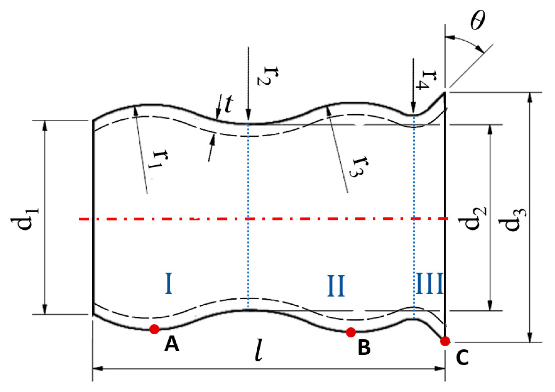
2.1. Shape and Geometry

Figure 1 shows the geometrical shape of an irregular bellows. The irregular bellows has a symmetric axis, but it is not symmetric at its both ends. It consists of two bulged regions (zones I and II) and a conical region (zone III) with an inclination angle θ. In the two bulged regions, the tube surfaces are two circular arcs with different curvature radii (r1 and r3) and are connected by a circular arc of radius r2. The conical part (zone III) connects zone II with another circular arc of radius r4. t is the bellows thickness. d1, d2 and d3 are the diameters of the bellows at the left end, middle part, and the right end, respectively. l is the bellows length. Since the maximal thinning ratio usually occurs at points A, B, or C, the thickness distribution and thinning ratios at points A, B, and C are discussed in the following sections. Conventional metal bellows have multiple wrinkles or convolutions. As a result that the outer diameter of each convolution is much larger than its inner diameter, they can be manufactured by hydraulic bulging and die folding processes. The outer diameter d3 in Figure 1 is not much larger than its original tube diameter d1. This kind of irregular bellows can only be made by a hydraulic bulging process under a closed die set.

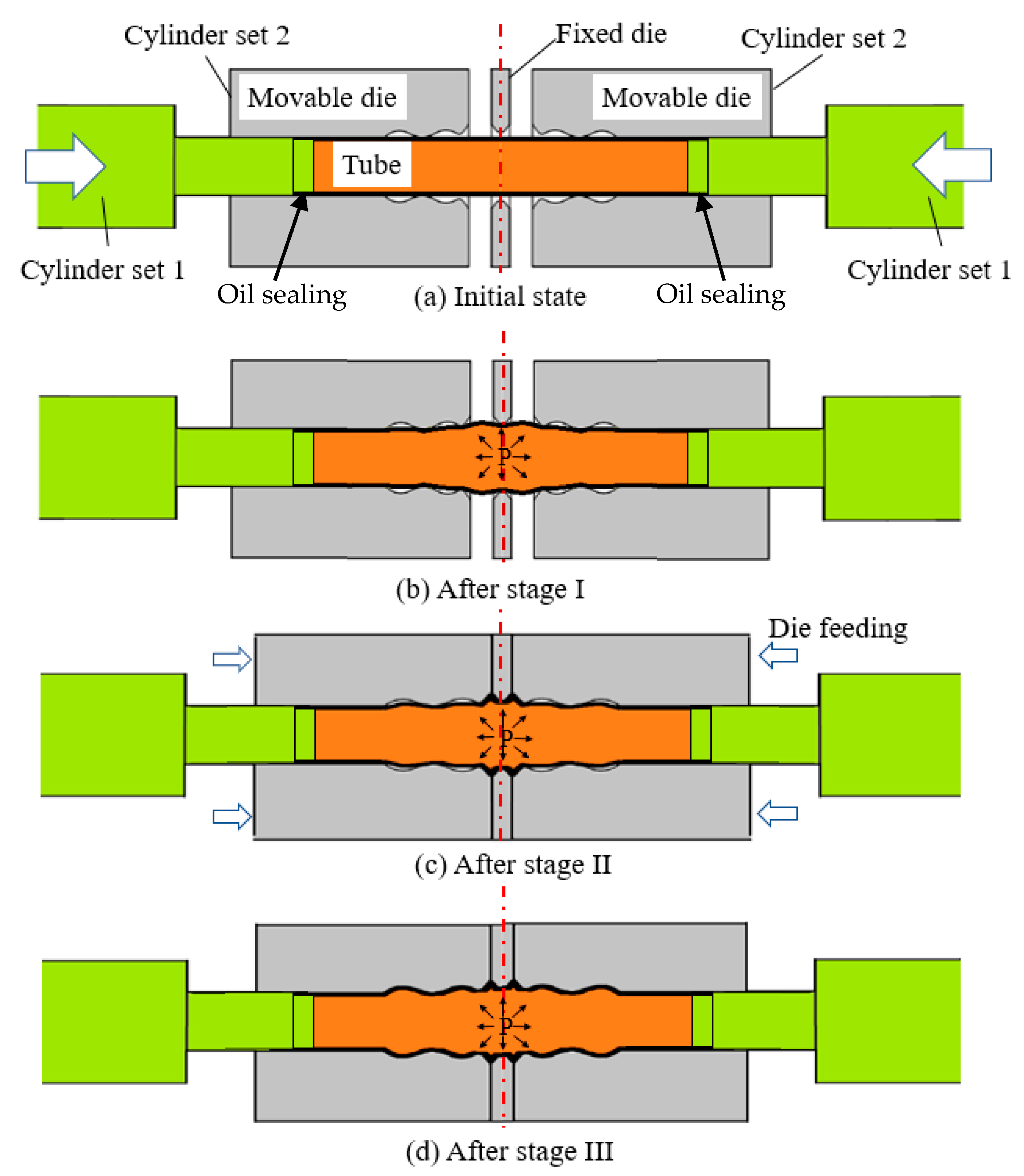
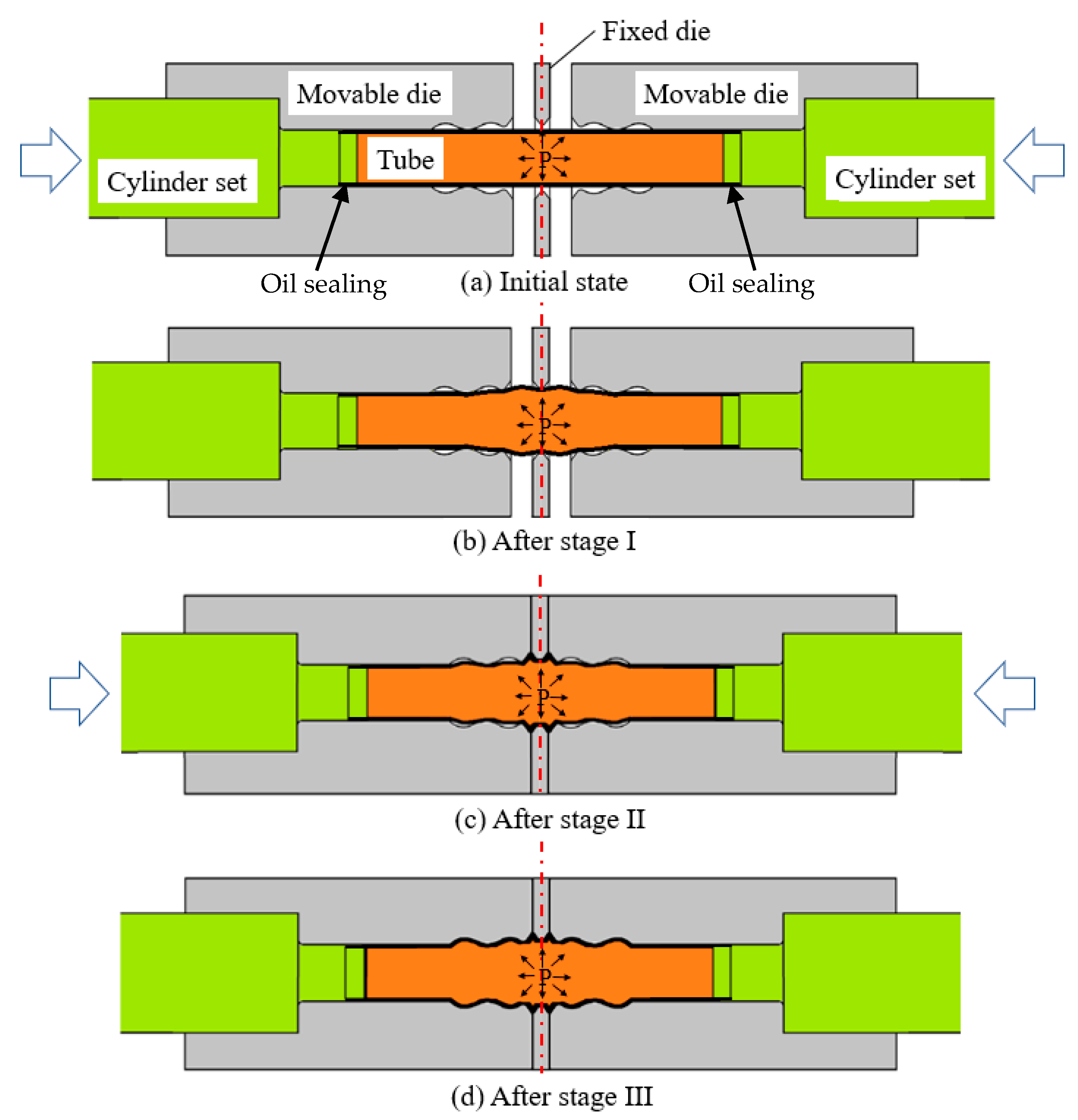
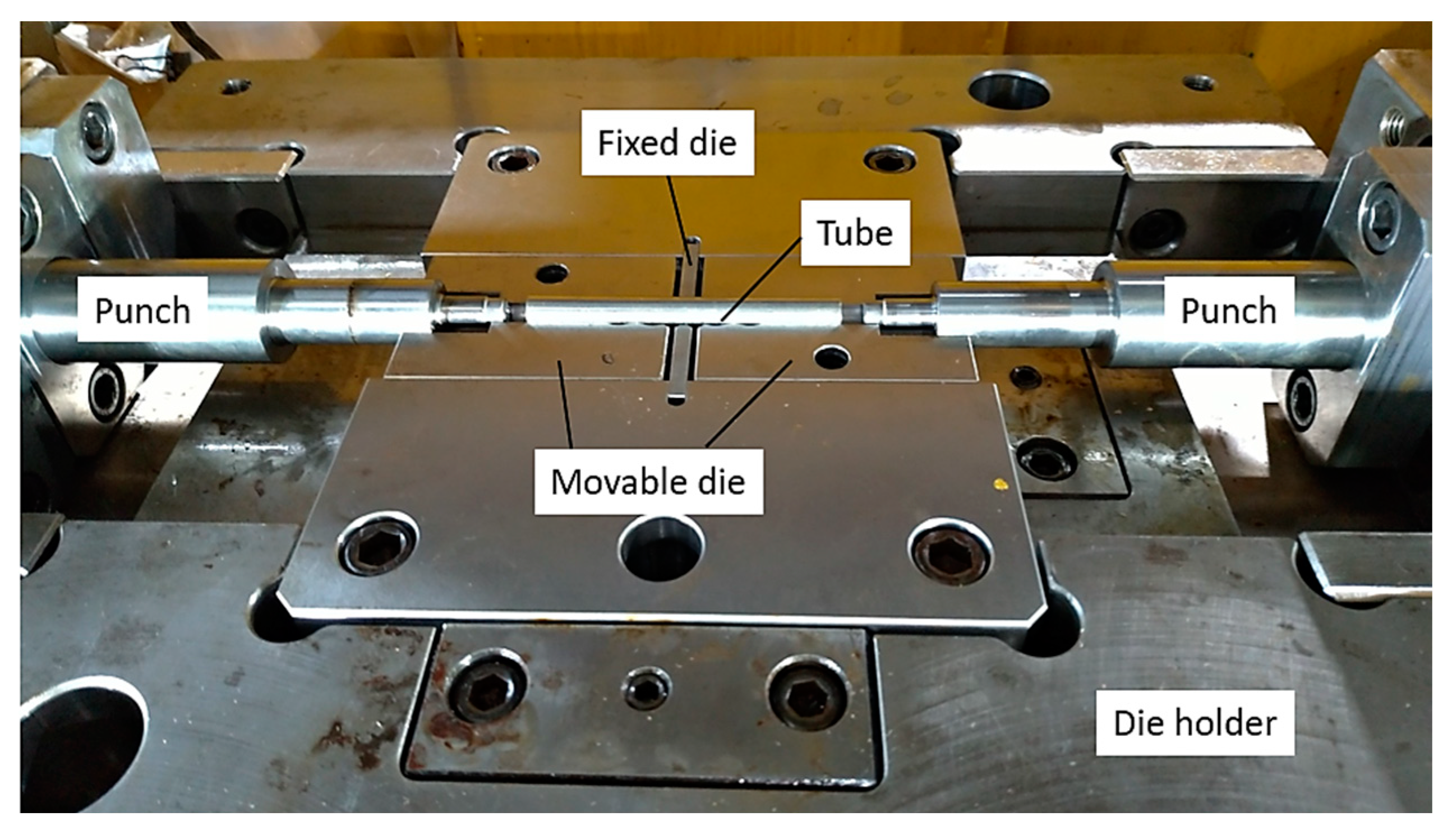
2.2. Movable Die Design

To increase the productivity and balance the axial forces from the left and right punches, a hydroforming die set is designed to manufacture two bellows in one forming pass. Another irregular bellows with inverse direction is allocated at the right hand side, as shown in Figure 2a. The central part (zone C) connecting the conical regions of the two bellows is designed to let the tube flow into the conical part easily. Part A at both ends of the die set is designed as a guiding zone. After forming, parts A and C of the formed product would be cut off and part B would be the desired irregular bellows products.
For a movable die design, the hydroforming die set is divided into three parts: a fixed central die (zone C) and two movable dies (zones A and B) as shown in Figure 2b. The movable dies are separated from the fixed die by a gap of width L at the beginning of the process. The hydroforming process is divided into three stages. The relationship between the internal pressure and the die movement at each stage is shown in Figure 3, where L is the die gap width, P1 and P2 are the pressures at the free bulging stage (stage I) and die feeding stage (stage II), respectively, and Pf is the final pressure at the calibration stage.
The geometric configurations of the dies and tube for the three stages in the hydroforming process are shown in Figure 4. The initial geometric configuration between the punch, dies and tube is shown in Figure 4a. At the first stage, only internal pressure is applied into the tube to bulge the tube and make the tube undergo slight plastic deformation, as shown in Figure 4b. At the second stage, movable dies start to move forward to make the tube flow into the die corner, as shown in Figure 4c. At this stage, the internal pressure can be adjusted. At the final stage, the movable dies are closed completely, and a higher internal pressure is input to calibrate the tube to fill into the die corner completely, as shown in Figure 4d.

2.3. Movable Die Feeding Types

According to hydroforming machine categories, two kinds of movable die feeding types are proposed. For a hydroforming machine with two sets of hydraulic cylinders, one set of cylinders is used to push punches to seal the tube. The other set of cylinders is used to push the movable dies forward. This kind of feeding type is called feeding type 1. The geometric configurations of the movable die, tube, punch, and hydraulic cylinders for movable die feeding type 1 are shown in Figure 5. At the beginning, the tube is placed inside the die set and is sealed at both ends by the punch head pushed by cylinder set 1, as shown in Figure 5a. Then, hydraulic oil is input to bulge the tube, as shown in Figure 5b. During the die feeding stage (stage II), movable dies are pushed forward by cylinder set 2. The configurations of the tube and die after stage II are shown in Figure 5c. Finally, a calibration pressure is applied to make the tube material fill into the die cavities as much as possible, as shown in Figure 5d.
For a hydroforming machine with only one set of hydraulic cylinders, the movable die movement and oil sealing function have to be accomplished by the only one set of cylinders simultaneously. This kind of feeding type is called feeding type 2. The forming procedures for feeding type 2 are also divided into three stages, as shown in Figure 6. At stage I, the cylinder set is used to seal the tube as the operation in feeding type 1. Initially, a small gap between the movable die and punch shoulder should be set. The gap is closed by the movement of the punch (cylinder) and the oil sealing function is accomplished accordingly. At stage II, only the one cylinder set is used to push punches to seal the tube and push the movable dies moving forward simultaneously. That is, the moving distance of movable die is the same as that of the punch, as shown in Figure 6c. At stage III, a higher internal pressure is input to calibrate the tube like the procedure in feeding type 1.

3. Finite Element Simulations

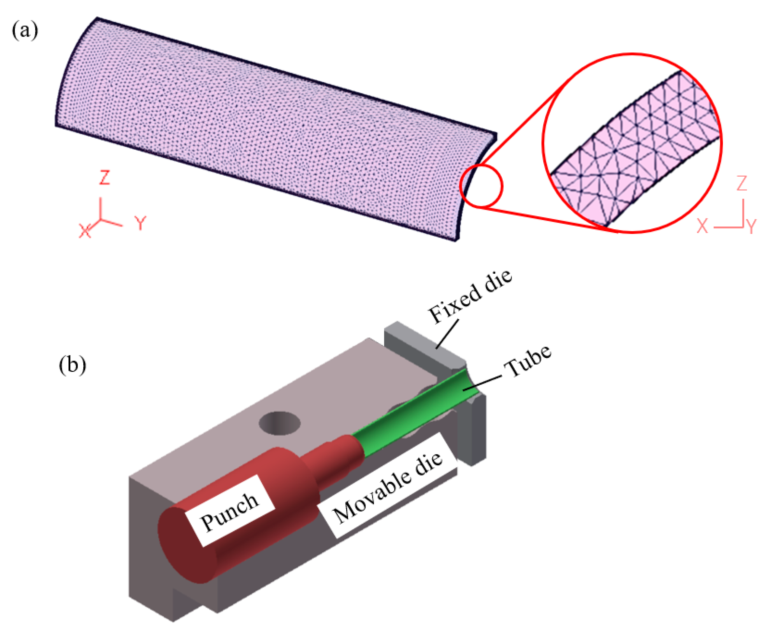
3.1. Finite Element Modeling

A commercial finite element software, DEFORM-3D, was used to simulate the hydroforming process. The tube material used in this study was stainless steel of SUS321. Tensile tests were conducted to obtain the mechanical properties and flow stress of SUS321. Table 1 shows the parameters used in the finite element simulations. Table 2 shows the dimensions of the irregular bellows simulated. The definition of the geometric variables is shown in Figure 1. To shorten the simulation time, only one quarter of the objects were used in the FE simulations. Convergence analyses were implemented. Finite element simulations with total element numbers of 20,000, 30,000, 40,000, 50,000, 65,000, and 75,000 were conducted. The simulation results of the maximal thinning ratio in the product were listed and the difference between two successive simulation results were compared. It was found that the relative differences in the maximal thinning ratios in the product decrease to within 1% as the total element number increases to 65,000. Accordingly, 75,000 tetrahedron elements were set for the tube in the subsequent finite element simulations. The minimal mesh length is about 0.09 mm. There are five layers of meshes in the thickness direction. The mesh configuration in the tube and the geometric configurations between the tube, punch, movable die and fixed die in FE simulations are shown in Figure 7.

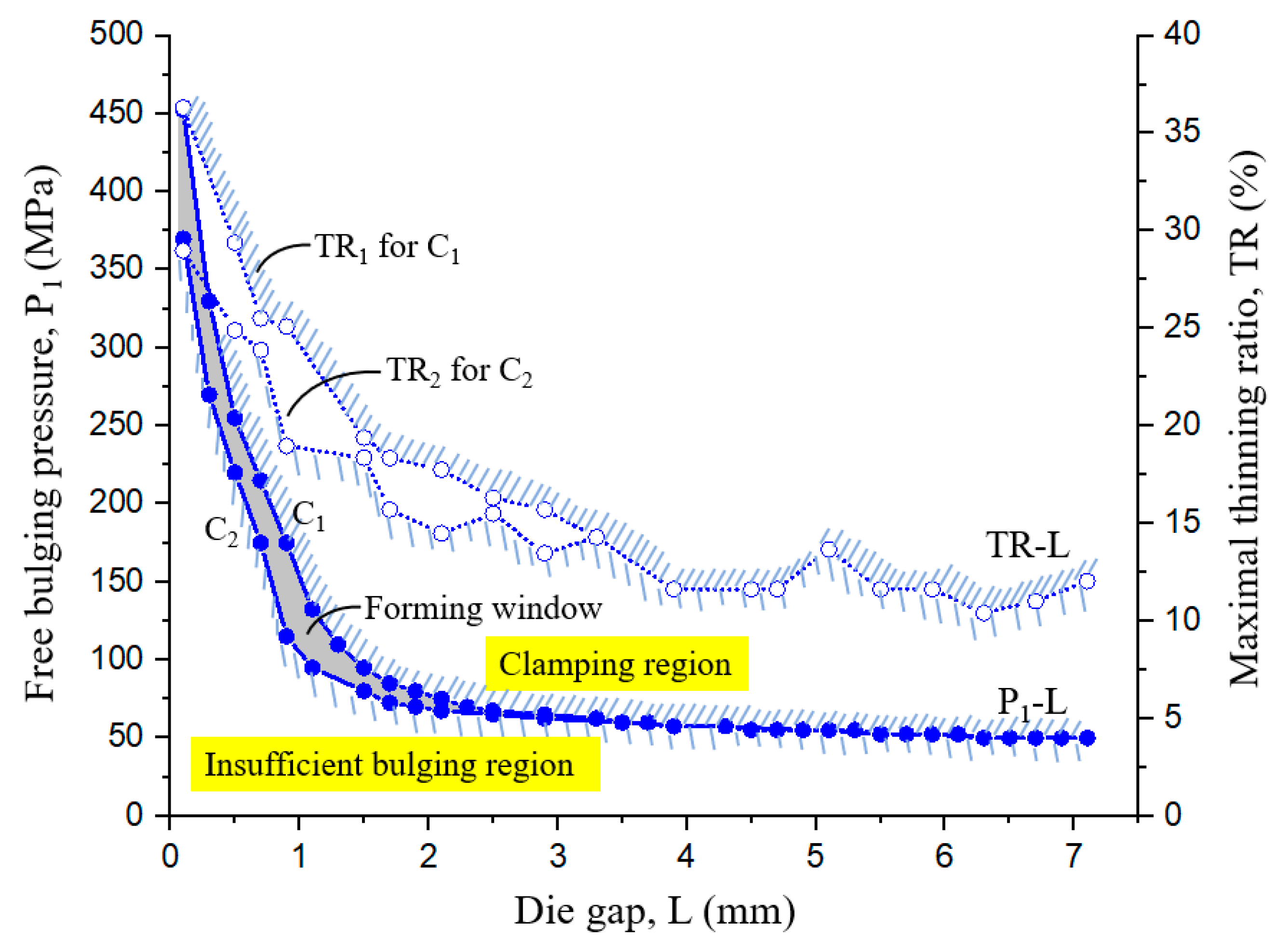
3.2. Forming Windows for Different Feeding Types

In tube hydroforming of a product with small corner radii, a quite high hydraulic pressure is generally required and some defects probably occur if the loading path is not controlled appropriately [17]. The biggest advantage of applying movable dies is the reduction of the required maximal internal pressure. Figure 8 shows the comparisons of the product geometries and internal pressures needed with and without movables die design. Using a loading path of feeding type 1, the internal pressure is set as P1 = P2 = 57.5 MPa, Pf = 120 MPa, and the die gap width is set as L = 3.9 mm, an irregular bellows product with desired shape and a small corner radius of r = 0.63 mm was obtained, as shown in Figure 8a, Using a loading path of feeding type 2, a good bellows shape was also obtained with an internal pressures of P1 = P2 = 50 MPa, as shown in Figure 8b. However, using a conventional hydroforming process without movable die design, a bellows shape with a large corner radius of 4.7 mm was obtained by a quite large internal pressure of 200 MPa, as shown in Figure 8c. Clearly, using movable die design, a quite small corner radius in the hydroformed bellows could be obtained with a much smaller internal pressure.

3.2.1. Forming Windows for Feeding Type 1

The process schedule for feeding type 1 is shown in Figure 5, in which only the movable die is pushed forward and the punch is used for oil sealing function only. A larger die gap L can make more tube material flow into the die cavity and can make the required bulging pressure smaller. However, if L is too large, the tube is probably bulged into the cavity too much at the free bulging stage (stage I), and the tube material would probably be clamped between the fixed and movable dies and this defect is called clamping. Thus, it is important to find the limitation of L and the relationship between L and the free bulging pressure, P1, under which no clamping occurs.
Theoretically, there is no limitation for L in feeding type 1, because of no wrinkling or buckling occurring in feeding type 1. However, for a fixed die gap L, there is a constrained boundary for the bulging pressure P1. The minimum bulging pressure depends on the tube yield stress, die contact geometries, and tube dimensions. In other words, the bulging pressure must be large enough to make the tube deform plastically. Generally, the time period at stage II of the loading path in Figure 3 is quite short. To simplify the loading path, let the internal pressure Pi = P1 = P2 [4,9]. From finite element simulations, the forming windows or formability ranges between L and Pi for feeding type 1 and the corresponding maximal thinning ratio curves are shown in Figure 9. Firstly, set the die gap L = 0.2 mm and divide the internal pressure Pi between 300 and 500 MPa into many small levels, with which the FE simulations are conducted. From the series of simulation results, the lower and upper critical internal pressures for sound products are determined. After that, L is increased with an increment of ΔL = 0.2 mm and a series of simulations are conducted to determine the corresponding lower and upper critical internal pressures. The simulations are repeated until L reaches 7 mm and all the lower and upper critical internal pressures for each L are obtained. Finally, curves C1 and C2 are drawn to represent the upper and lower boundaries of the safe region, respectively. Curve C1 represents the upper critical values of Pi, over which clamping defects occur, and C2 presents the lower critical values of Pi, under which the tube cannot fill up the die cavity after stage II. In other words, the region on the upper-right side of curve C1 means the occurrence of tube clamping, and the region on the lower-left side of curve C2 means that the die cavity cannot be filled up with the tube completely. The region between curves C1 and C2 is called the forming window, in which no clamping occurs and there is complete tube filling in the die cavity. From Figure 9, it is clear that the range of the allowable bulging pressure gets narrow as the die gap width L increases. When L is 3.3 mm, the allowable bulging pressure range is smaller than 5 MPa. At the maximal die gap, L = 7.1 mm, the bulging pressure can be reduced to 46 MPa, which is the minimum bulge pressure to make the tube deform plastically with a yielding stress of 403 MPa, an initial tube thickness of t0 = 0.49 mm, and an initial tube diameter of do = 9.53 mm. The maximal thinning ratios of the formed bellows after calibration for curves C1 and C2 are also shown in Figure 9. Clearly, the mean value of the maximal thinning ratios decreases greatly with the die gap width L as 0.1 < L < 3 mm.

3.2.2. Forming Windows for Feeding Type 2

The process schedule for feeding type 2 is shown in Figure 6, in which the movable dies and tube are pushed forward simultaneously by one set of punches. The maximal die gap L is determined from the volume of the formed bellows and the initial tube dimensions. The geometrical configuration of a tube bulged to fill up the die cavities perfectly without thinning is shown in Figure 10. The radius functions of the outer and inner surfaces of the formed tube along the symmetric z axis are assumed as f(z) and g(z), respectively. The formed bellows is composed of seven arcs (zones 1–5, 7, and 9) and three straight lines (zones 6, 8, and 10), as shown in Figure 10. Arcs 1, 3, 5, and 9 curve upward, while arcs 2, 4, and 7 curve downward. A minus sign has to be input in front of the radius functions for arcs curving upward. Therefore, the radius functions at zones 1–5, 7, and 9 at the outer surface can be expressed as:
f i ( z ) = ( 1 ) i [ R i 2 ( z z c i ) 2 ] 1 / 2 + r c i ,   z i 1 z z i ,   i = 1 5 ,   and   9
f 7 ( z ) = [ R 7 2 ( z z c 7 ) 2 ] 1 / 2 + r c 7 ,   z 6 z z 7
where Ri is the radius of curvature at the outer surface of section i, i = 1–5, 7, and 9. z c i and r c i are the z and r coordinates of the arc centers at zones 1, 3, 5, and 9. z i 1 and z i are the integration boundaries of zone i at the outer surface. The radius functions at zones 6, 8, and 10 are straight lines, and can be expressed as:
f 6 ( z ) = z 15.959 ,   z 5 z z 6
f 8 ( z ) = 29.912 z ,   z 7 z z 8
f 10 ( z ) = 5.684 ,   z 9 z z 10
The inner surface is also composed of seven arcs and three straight lines. The thickness of the formed bellows is assumed to be uniform and the same as the initial thickness of the tube, t0 = 0.49 mm. Thus, the arcs at zones 1–5, 7, and 9 have the same circular center as those of the outer surface, fi(z). The radius functions of each zone are listed below.
g j ( z ) = ( 1 ) j [ R j 2 ( z z c j ) 2 ] 1 2 + r c j ,   z j 1 z z j ,   j = 1 5 ,   and   9
g 7 ( z ) = [ R 7 2 ( z z c 7 ) 2 ] 1 / 2 + r c 7 ,   z 6 z z 7
where R j is the radius of curvature at the inner surface of section j, j = 1–5, 7, and 9. z j is the integration boundary of each zone of the inner surface. The straight lines at the inner surface have the same slopes as those at the outer surface, so the radius functions at zones 6, 8, and 10 can be expressed as
g 6 ( z ) = z 16.651 ,   z 5 z z 6
g 8 ( z ) = 29.219 z ,   z 7 z z 8
g 10 ( z ) = 5.194 ,   z 9 z z 10
The relationship between the radii of curvature at the outer and inner surfaces can be expressed as:
| R i R i | = t 0
The volume of the finally formed bellows, Vb, can be found using the disk integration method as below:
V b = π i = 1 10 z i 1 z i f 2 ( z )   d z π j = 1 10 z j 1 z j g 2 ( z )   d z
The tube volume can be written as below.
V t = π 4 ( d o 2 d i 2 ) l 0
where do and di is the initial outer and inner tube diameters, and l0 is the tube length. The volume of the formed bellows must be equal to that of the tube, i.e., Vb = Vt. From Equations (12) and (13), l0 can be determined. The maximal die gap Lmax is the difference between the die length l e , as shown in Figure 2a and Figure 10, and the initial tube length l 0 as below.
L max = l 0 l e
According to the dimensions of the formed bellows shown in Table 2, the volume of the formed bellows by Equation (12) can be obtained as 378.65 mm3. If do = 9.53 mm, di = 8.55 mm and le = 22.2 mm, the initial tube length is l0 = 27.81 mm, and the maximal die gap is Lmax = 5.61 mm.
Figure 11 shows the forming windows or formability ranges between L and Pi for feeding type 2 and the corresponding maximal thinning ratio curves. Generally, the range of allowable forming pressure becomes narrower as the die gap L increases. The maximal die gap Lmax obtained by FE simulations is 5.5 mm which is quite close to the theoretically calculated value of 5.61 mm by Equation (14). In feeding type 2, wrinkling probably occurs at a large axial feeding and a low internal pressure. Therefore, the region on the upper-right side of curve C1 means the occurrence of tube clamping just like the case for feeding type 1, whereas the region on the lower-left side of curve C2 means that tube buckling occurs or the die cavity cannot be filled up with the tube completely. The region between curves C1 and C2 is the forming window, in which no clamping occurs and the die cavity is filled up with the tube completely. As L exceeds 4.7 mm, the allowable pressure becomes so low that tube wrinkling would probably occur due to axial feeding from the punch. However, because the movable dies also move forward along with the punches simultaneously, the tube wrinkling could be smoothed out by the movable die surfaces and the calibration pressure at the last stage.
From Figure 9 and Figure 11 for the forming windows using feeding types 1 and 2, it is known that the maximal thinning ratio can be reduced greatly by increasing the die gap L. Meanwhile, the bulging pressure can also be reduced greatly. For example, if the die gap is set as L = 2–4 mm, the maximum thinning ratios can be reduced to about TR = 11–15% and TR < 10% for feeding types 1 and 2, respectively. On the other hand, the bulging pressure required with L = 0.1 mm can be reduced to only approximately one sixth of the original pressure if the die gap is set as L > 3 mm.
Strain hardening exponents exhibit the formability of the tube material and the interface friction affects the flowability of the tube material during the forming process. The final total strain of the deforming tube is not so large and the relative movement between the tube and die is also not so severe in the hydroforming process with the proposed movable die concept. Thus, the effects of the strain hardening exponent and friction coefficient on the upper and lower boundaries of the safe region are considered to be small and limited.

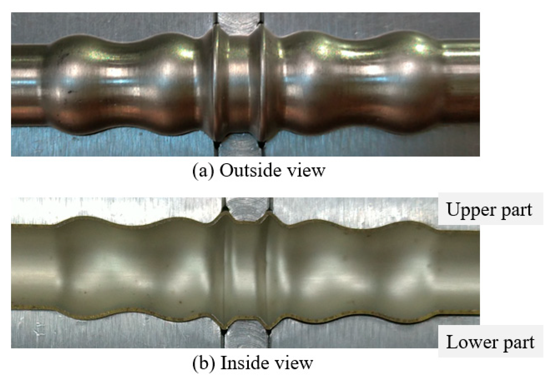
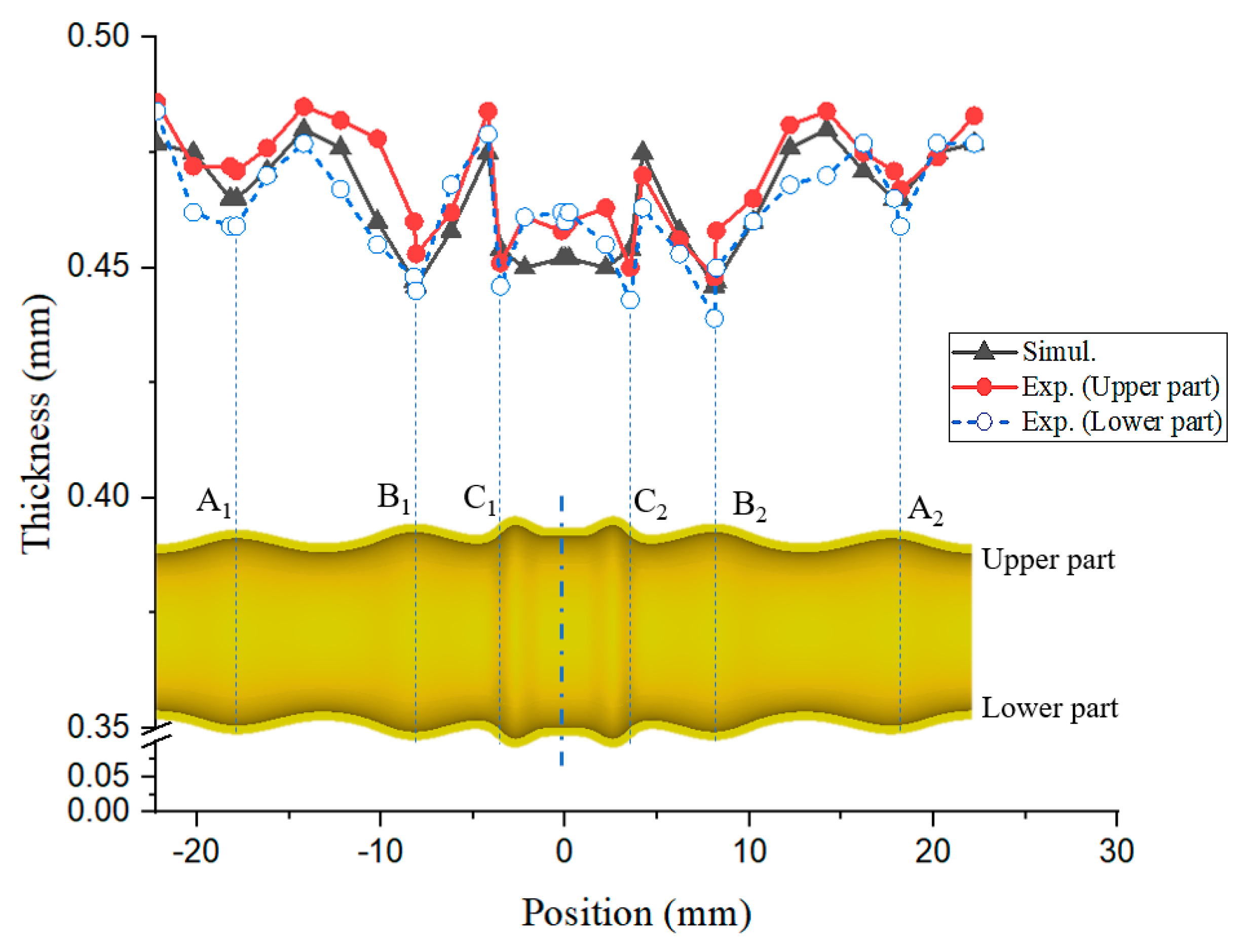
4. Tube Hydroforming Experiments

A hydroforming machine with only one pair of cylinders was used to conduct tube hydroforming experiments of irregular bellows. Thus, movable die feeding type 2 was adopted in the experiments. This machine has a capacity of an internal pressure of 200 MPa, a die closing force of 200 ton, and an axial stroke of 150 mm. The geometric configurations of a self-designed die set is shown in Figure 12. As a result that two irregular bellows are formed at one pass, one pair of movable dies, one fixed die, two gaskets, and one pair of T-shape slideways in the upper track were designed and assembled in the upper die set. To avoid the upper movable dies dropping from the upper die holder, two T-shape slots were designed on the top surface of the movable dies. Four gaskets were inserted between the movable dies and the die holders to adjust the die gap width L between the movable die and fixed die. Four springs were used to keep the movable dies at the initial positions. As a result that the forming stage II in the loading path shown in Figure 3 is quite short, a constant internal pressure (P1 = P2) [5,14] was set in the hydroforming experiments. Stainless steel SUS321 seamless tubes with an outer diameter of 9.53 mm were used as the specimens in the hydroforming experiments. The thickness distributions of the tubes were measured and some thickness variations of 0.45–0.49 mm in the circumferential direction were found. The average thickness of the tubes was about 0.47 mm. After experiments, the hydroformed irregular bellows were cut into two halves by electric discharge wire cutting and the thickness distributions of the products were measured. Figure 13 shows the completed lower part of the movable die set for the hydroforming experiments.
Hydroforming experiments of irregular bellows with a loading path of internal pressure P1 = P2 = 70.2 MPa and die gap width of L = 1.47 mm were carried out. The appearances at the outside and inner views of a hydroformed bellows after stage II of die feeding are shown in Figure 14a,b, respectively. Generally, a sound product with desired shape was obtained successfully. The central part and both ends of the product would be cut off and two irregular bellows with desired shape and dimensions could be obtained.
The simulative and experimental thickness distributions at the upper and lower parts of the hydroformed products are shown in Figure 15. Generally, the thicknesses at the upper part are larger than those at the lower part of the hydroformed bellows, because there was some variation in the initial thickness distribution of the tube. Generally, the simulative thickness distribution was quite close to the experimental values. The thinnest positions occurred at points B1, and B2. Nevertheless, the simulative thinning ratio was only TR = 5.11%, and the experimental values were only TR = 4.47% at B1 and TR = 5.53% at B2.
The simulative and experimental thicknesses and diameters of the formed product at the left and right parts are summarized in Table 3. Even though there was some variation in the thickness at the left and right positions, the deviations are all below 2%. The diameters at positions A, B, and C were also measured to understand whether the die cavity is filled up with the tube material or not. The diameters at positions C1 and C2 are 13.40 and 13.45 mm, respectively, which are larger than 13.25 mm, the designed diameter at the tip of the taper part. The diameters at positions A and B are also quite close to the diameters at the corresponding die cavity. In other words, all the die cavities are filled up with the tube and two sound bellows with designed geometric dimensions were obtained. The maximal deviations in thicknesses and diameters between simulation and experimental values are 1.57% and 5.31%, respectively.

5. Conclusions

In this paper, a tube hydroforming process using a novel movable die and loading path design was developed to manufacture irregular bellows with small thinning ratios in the formed product. A finite element simulation software “DEFORM 3D” was used to analyze the plastic deformation of the tube within the die cavity using the proposed movable die design concept. Two kinds of die feeding types were proposed to make the maximal thinning ratio in the formed bellows and the needed internal pressure as small as possible. Using the movable die design with an appropriate die gap width, the internal forming pressure needed can be reduced to only one sixth of the internal pressure needed without the movable die design. From the forming windows for the two proposed die feeding types, it is known that a larger die gap width is beneficial to reduce the free bulging pressure. However, a narrow range for the allowable forming pressure probably results in the occurrence of defects such as clamping and buckling if the forming pressure is not controlled precisely. Moreover, an excessively large die gap width may increase the maximal thinning ratio for die feeding type 1. Thus, a die gap width of 4 mm is an appropriate value that can improve the thickness distribution and reduce greatly the forming pressure for the both feeding types. Maximal thinning ratios of 11.63% and 5.31% could be obtained for feeding types 1 and 2, respectively. Finally, a movable die set was designed and manufactured and tube hydroforming experiments using feeding type 2 based on the forming conditions used in the finite element simulations were conducted. Comparisons of the diameters and the thickness distributions of the formed product between simulative and experimental results were carried out. The maximal deviations in thickness and diameter between simulative and experimental results were 1.57% and 5.31%, respectively, which validated the finite element modeling and the movable die design concept proposed in this paper.

Author Contributions

Conceptualization, methodology, research supervision, and writing—review and editing were conducted by Y.-M.H. Simulations, experiments, validation, and writing—original draft preparation were completed by Y.-J.T. Both authors have read and agreed to the published version of the manuscript.

Funding

The authors would like to extend their thanks to the Ministry of Science and Technology of the Republic of China under Grant no. MOST 106-2221-E-110 -029 -MY3. The advice and financial support of MOST are greatly acknowledged.

Conflicts of Interest

The authors declare no conflict of interest.

References

  1. Ahmetoglu, M.; Altan, T. Tube hydroforming: State-of-the-art and future trends. J. Mater. Process. Technol. 2000, 98, 25–33. [Google Scholar] [CrossRef]
  2. Kang, B.H.; Lee, H.Y.; Shon, S.M.; Moon, Y.H. Forming various shapes of tubular bellows using a single-step hydroforming process. J. Mater. Process. Technol. 2007, 194, 1–6. [Google Scholar] [CrossRef]
  3. Faraji, G.H.; Mosavi Mashhadi, M.; Norouzifard, V. Evaluation of effective parameters in metal bellows forming process. J. Mater. Process. Technol. 2009, 209, 3431–3437. [Google Scholar] [CrossRef]
  4. Lee, S.W. Study on the forming parameters of the metal bellows. J. Mater. Process. Technol. 2002, 130–131, 47–53. [Google Scholar] [CrossRef]
  5. Bakhshi-Jooybari, M.; Elyasi, M.; Gorji, A. Numerical and experimental investigation of the effect of the pressure path on forming metallic bellows. J. Eng. Manuf. 2009, 224, 95–101. [Google Scholar] [CrossRef]
  6. Ngaile, G.; Lowrie, J. Punch design for floating based micro-tube hydroforming die assembly. J. Mater. Process. Technol. 2018, 253, 168–177. [Google Scholar] [CrossRef]
  7. Shinde, R.A.; Patil, B.T.; Joshi, K.N. Optimization of Tube Hydroforming Process (without Axial feed) by using FEA Simulations. In Proceedings of the 3rd International Conference on Innovations in Automation and Mechatronics Engineering, Vallabh Vidhyanagar, India, 5–6 February 2016; pp. 398–405. [Google Scholar]
  8. Elyasi, M.; Bakhshi-Jooybari, M.; Gorji, A.; Hosseinipour, S.J.; Nourouzi, S. New die design for improvement of die corner filling in hydroforming of cylindrical stepped tubes. J. Eng. Manuf. 2009, 223, 821–827. [Google Scholar] [CrossRef]
  9. Zhang, Q.; Wu, C.D.; Zhao, S.D. Numerical simulation on hydroforming tube-like eccentric shaft part by using movable die. In Proceedings of the 5th International Conference on Tube Hydroforming, Hokkaido, Japan, 24–27 July 2011; pp. 149–152. [Google Scholar]
  10. Tomizawa, A.; Kubota, H.; Kurokawa, H.; Kojima, M. Development of tube hydroforming technology using axial movable dies. JSTP 2015, 56, 40–46. [Google Scholar] [CrossRef] [Green Version]
  11. Hwang, Y.M.; Chen, Y.C. Study of compound hydroforming of profiled tubes. Procedia Eng. 2017, 207, 2328–2333. [Google Scholar] [CrossRef]
  12. Hwang, Y.M.; Hsieh, S.Y.; Kuo, N.J. Study of large-expansion-ratio tube hydroforming with movable dies. Key Eng. Mater. 2016, 725, 616–622. [Google Scholar] [CrossRef]
  13. Yuan, S.J.; Wang, X.S.; Liu, G.; Wang, Z.R. Control and use of wrinkles in tube hydroforming. J. Mater. Process. Tchnol. 2007, 182, 6–11. [Google Scholar] [CrossRef]
  14. Xu, Y.; Zhang, S.H.; Cheng, M.; Song, H.W.; Zhang, X.S. Application of pulsating hydroforming in manufacture of engine. Procedia Eng. 2014, 81, 2205–2210. [Google Scholar] [CrossRef] [Green Version]
  15. Imaninejad, M.; Subhash, G.; Loukus, A. Loading path optimization of tube hydroforming process. Int. J. Mach. Tools Manuf. 2005, 45, 1504–1514. [Google Scholar] [CrossRef]
  16. Hama, T.; Ohkubo, T.; Kurisu, K.; Fujimoto, H.; Takuda, H. Formability of tube hydroforming under various loading paths. J. Mater. Process. Technol. 2006, 177, 676–679. [Google Scholar] [CrossRef]
  17. Liu, G.; Yuan, S.; Teng, B. Analysis of thinning at the transition corner in tube hydroforming. J. Mater. Process. Technol. 2006, 177, 688–691. [Google Scholar] [CrossRef]
Figure 1. Geometrical configuration of an irregular bellows.
Metals 10 01518 g001
Figure 2. Cross-sectional configurations of designed die set. (a) Traditional die set; (b) Movable die set.
Metals 10 01518 g002aMetals 10 01518 g002b
Figure 3. Designed loading path in hydroforming process with movable dies.
Metals 10 01518 g003
Figure 4. Geometric configurations of dies and tube at each stage. (ad): Initial State to Stage III.
Metals 10 01518 g004
Figure 5. Forming procedures for feeding type 1 with two sets of cylinders (only movement of movable die). (ad): Initial State to After Stage III.
Metals 10 01518 g005
Figure 6. Forming procedures for feeding type 2 with one set of cylinders (Simultaneous movement of movable die and punch). (ad): Initial State to After Stage III.
Metals 10 01518 g006
Figure 7. (a) Mesh configuration in tube, (b) geometric configurations between tube, punch, movable die, and fixed die in FE simulations.
Metals 10 01518 g007
Figure 8. Comparisons of hydroformed bellows shapes with and without movable die design.
Metals 10 01518 g008
Figure 9. Forming windows and maximal thinning ratios for feeding type 1.
Metals 10 01518 g009
Figure 10. Geometric configurations of formed bellows. (Left-half part).
Metals 10 01518 g010
Figure 11. Forming windows for feeding type 2.
Metals 10 01518 g011
Figure 12. Geometric configurations of self-designed movable die sets.
Metals 10 01518 g012
Figure 13. Completed lower part of movable die set for hydroforming experiments.
Metals 10 01518 g013
Figure 14. Appearance of hydroformed product after loading path stage II. (L = 1.47 mm, P1 = 70.2 MPa).
Metals 10 01518 g014
Figure 15. Thickness distributions of formed product after loading path stage II. (L = 1.47 mm, P1 = 70.2 MPa).
Metals 10 01518 g015
Table 1. Forming parameters used in FE simulations.
MaterialSUS321
Young’s modulus (GPa)178
Yield stress (MPa)403
Flow stress (MPa)σ = 403 + 1270 ε0.66
Poisson’s ratio0.33
Tube outer diameter, do (mm)9.53
Tube thickness, t0 (mm)0.49
Punch velocity (mm/s)0.1
Movable die velocity (mm/s)0.1
Friction coefficient0.05
Mesh number75,000
Mesh layer number in thickness direction4
Minimum mesh length (mm)0.09
Table 2. Dimensions of simulated irregular bellows.
VariablesValues
d110.08 mm
d29.65 mm
d313.25 mm
r15.84 mm
r27.62 mm
r35.94 mm
r41.27 mm
l 18.33 mm
θ 45°
Table 3. Simulative and experimental thicknesses and diameters of formed product after stage II.
Experimental Results (mm)Simulation (mm)
Average thicknesstA1 = 0.465
(Deviation = 0%)
tA2 = 0.468
(Deviation = 0.64%)
tA = 0.465
tB1 = 0.449
(Deviation = 0.67%)
tB2 = 0.444
(Deviation = 0.45%)
tB = 0.446
tC1 = 0.449
(Deviation = 1.11%)
tC2 = 0.447
(Deviation = 1.57%)
tC = 0.454
DiameterdA1 = 11.64
(Deviation = 4.47%)
dA2 = 11.64
(Deviation = 4.47%)
dA = 11.12
dB1 = 11.84
(Deviation = 0.42%)
dB2 = 11.84
(Deviation = 0.42%)
dB = 11.79
dC1 = 13.40
(Deviation = 5.31%)
dC2 = 13.45
(Deviation = 5.28%)
dC = 12.74
Publisher’s Note: MDPI stays neutral with regard to jurisdictional claims in published maps and institutional affiliations.

